EP2439102A2 - Child seat - Google Patents
Child seat Download PDFInfo
- Publication number
- EP2439102A2 EP2439102A2 EP11008064A EP11008064A EP2439102A2 EP 2439102 A2 EP2439102 A2 EP 2439102A2 EP 11008064 A EP11008064 A EP 11008064A EP 11008064 A EP11008064 A EP 11008064A EP 2439102 A2 EP2439102 A2 EP 2439102A2
- Authority
- EP
- European Patent Office
- Prior art keywords
- leg
- support
- base
- child seat
- frame
- Prior art date
- Legal status (The legal status is an assumption and is not a legal conclusion. Google has not performed a legal analysis and makes no representation as to the accuracy of the status listed.)
- Granted
Links
Images


Classifications
-
- B—PERFORMING OPERATIONS; TRANSPORTING
- B60—VEHICLES IN GENERAL
- B60N—SEATS SPECIALLY ADAPTED FOR VEHICLES; VEHICLE PASSENGER ACCOMMODATION NOT OTHERWISE PROVIDED FOR
- B60N2/00—Seats specially adapted for vehicles; Arrangement or mounting of seats in vehicles
- B60N2/24—Seats specially adapted for vehicles; Arrangement or mounting of seats in vehicles for particular purposes or particular vehicles
- B60N2/26—Seats specially adapted for vehicles; Arrangement or mounting of seats in vehicles for particular purposes or particular vehicles for children
- B60N2/28—Seats readily mountable on, and dismountable from, existing seats or other parts of the vehicle
- B60N2/2857—Seats readily mountable on, and dismountable from, existing seats or other parts of the vehicle characterised by the peculiar orientation of the child
- B60N2/286—Seats readily mountable on, and dismountable from, existing seats or other parts of the vehicle characterised by the peculiar orientation of the child forward facing
-
- B—PERFORMING OPERATIONS; TRANSPORTING
- B60—VEHICLES IN GENERAL
- B60N—SEATS SPECIALLY ADAPTED FOR VEHICLES; VEHICLE PASSENGER ACCOMMODATION NOT OTHERWISE PROVIDED FOR
- B60N2/00—Seats specially adapted for vehicles; Arrangement or mounting of seats in vehicles
- B60N2/02—Seats specially adapted for vehicles; Arrangement or mounting of seats in vehicles the seat or part thereof being movable, e.g. adjustable
- B60N2/20—Seats specially adapted for vehicles; Arrangement or mounting of seats in vehicles the seat or part thereof being movable, e.g. adjustable the back-rest being tiltable, e.g. to permit easy access
-
- B—PERFORMING OPERATIONS; TRANSPORTING
- B60—VEHICLES IN GENERAL
- B60N—SEATS SPECIALLY ADAPTED FOR VEHICLES; VEHICLE PASSENGER ACCOMMODATION NOT OTHERWISE PROVIDED FOR
- B60N2/00—Seats specially adapted for vehicles; Arrangement or mounting of seats in vehicles
- B60N2/24—Seats specially adapted for vehicles; Arrangement or mounting of seats in vehicles for particular purposes or particular vehicles
- B60N2/26—Seats specially adapted for vehicles; Arrangement or mounting of seats in vehicles for particular purposes or particular vehicles for children
- B60N2/28—Seats readily mountable on, and dismountable from, existing seats or other parts of the vehicle
- B60N2/2821—Seats readily mountable on, and dismountable from, existing seats or other parts of the vehicle having a seat and a base part
- B60N2/2824—Seats readily mountable on, and dismountable from, existing seats or other parts of the vehicle having a seat and a base part part of the base being supported by the vehicle frame
-
- B—PERFORMING OPERATIONS; TRANSPORTING
- B60—VEHICLES IN GENERAL
- B60N—SEATS SPECIALLY ADAPTED FOR VEHICLES; VEHICLE PASSENGER ACCOMMODATION NOT OTHERWISE PROVIDED FOR
- B60N2/00—Seats specially adapted for vehicles; Arrangement or mounting of seats in vehicles
- B60N2/24—Seats specially adapted for vehicles; Arrangement or mounting of seats in vehicles for particular purposes or particular vehicles
- B60N2/26—Seats specially adapted for vehicles; Arrangement or mounting of seats in vehicles for particular purposes or particular vehicles for children
- B60N2/28—Seats readily mountable on, and dismountable from, existing seats or other parts of the vehicle
- B60N2/2821—Seats readily mountable on, and dismountable from, existing seats or other parts of the vehicle having a seat and a base part
- B60N2/2827—Seats readily mountable on, and dismountable from, existing seats or other parts of the vehicle having a seat and a base part part of the base being supported by the seat sub-frame
Definitions
- This application relates generally to a child seat.
- a child seat configured such that a main body shell is held on a relatively large base closely attached to the seat surface of a vehicle via a reclining mechanism.
- a child seat of this type often has a support leg provided on the front end of the base. By making this support leg rise up on a vehicle body floor in a state in which the child seat is secured onto a vehicle seat, it is possible to prevent the child seat from rotating forward during the frontal collision of the vehicle or the like. Therefore, the support leg can ensure the improved safety of the child seat.
- the child seat equipped with the support leg of this type often includes a child seat supporting device.
- the child seat supporting device includes a long support leg having a lower end supported by the vehicle body floor and a long support arm arranged in the longitudinal direction of the child seat supporting device that corresponds to an anterior-posterior direction of the vehicle.
- the rear end of the support arm is coupled to the lower end of a base seat and the front end thereof is coupled to the upper end of the support leg in a collapsible manner.
- this child seat supporting device if the child seat is to tilt forward around a restraint point at which a child is restrained (a fixed point at which the child is fastened by a seatbelt device) by an inertial force acting on the child seated in the child seat during the sudden deceleration of the vehicle or the like, a combination of the support leg and support arm in an L shape (or in the shape of a carpenter's square) in a lateral view of the vehicle supports the front end of the child seat. For example, the load acting on the child seat during the sudden deceleration of the vehicle or the like is transmitted from the support arm to the support leg and finally received by the vehicle body floor. This can prevent the child seat from tilting forward and sinking into the seat cushion of the vehicle seat.
- each of the support leg and the support arm of the child seat supporting device disclosed in Unexamined Japanese Patent Application KOKAI Publication No. 2001-239868 is made of a thin plate. Furthermore, the support arm is coupled to the upper end of the support leg in a collapsible manner in a state of protruding from the front end of the base seat by a predetermined length.
- the inertial force acting on the child seat in which the child is seated during the sudden deceleration of the vehicle, the frontal collision or the like is considerably high. Due to this, the member formed by coupling together the thin plate members into the L shape (or into the shape of the carpenter's square) is possibly unable to resist the inertial force.
- This child seat support leg device is configured such that a relatively high rigidity leg formed by bending a metal pipe and coupled to a horizontal member via a rotational unit supports the front surface of a base.
- the extensible pipe support leg disclosed in Unexamined Japanese Patent Application KOKAI Publication No. 2003-94994 is collapsed and contained in the lower surface of a base of a child seat. Due to this, a user need to raise up the support leg by one hand while releasing a lock mechanism provided in the rotational unit of the support leg device by the other hand with the base reclined on one side and kept unmovable. It is disadvantageously difficult to smoothly perform a series of operations while holding the child seat.
- a support-leg-length adjustment mechanism is disclosed in Unexamined Japanese Patent Application KOKAI Publication No. 2003-94994 .
- the mechanism is designed simply to insert an adjustment pin serving as a stopper into one of holes formed in the pipe support leg at predetermined intervals. Due to this, the support leg disclosed therein has problems that a clearance is generated between pipe parts of a double structure, rattling occurs, and abnormal noise occurs when in use.
- a child seat is a child seat (1) attached to a vehicle, including: a frame body (12) which is contained in a base (10) supporting a main body seating and restraining a child, which stiffens the base (10), and which is fixed and disposed in the base (10) so that a front end is exposed from a notch formed in the base (10); a rotational support (20) attached to a site exposed at the base front end (10a) of the frame body (12) to be rotatable around the frame body (12), and containing a lock mechanism capable of being locked and unlocked at a predetermined angle with respect to the frame body (12); and a support leg (30) including a leg support (31) capable of adjusting and holding a leg portion coupled to the rotational support (20) at a predetermined length, characterized in that the base (10) is fixed onto a vehicle seat (4), the support leg (30) is rotated around the rotational support (20) and adjusted to have a predetermined length at a base front end position, and the base (10)
- the frame body (12) comprises a pipe material that is processed substantially into u-shape including a front end frame (12a) located on the front end of the base (10), and a hardened frame (12b) connecting both sides of the front end frame (12a) and extending in a longitudinal direction of the base (10), and the rotational support (20) is rotatably attached to the front end frame (12a).
- the lock mechanism locks by inserting a lock pin (26) biased by a biaser contained in inner portion into a through-hole (14) formed in the frame body (12), and unlocks by pulling out the leg portion of the support leg (30) from the rotational support (20) by a predetermined distance against the biaser.
- a concave portion (11) capable of containing a part of the leg support (31) with the leg portion of the support leg (30) pulled out is formed in a bottom surface of the base (10).
- the leg support (31) includes a leg retaining hole (31b), into which the leg portion is slidably inserted, and includes a biasing and pressing member pressing the leg portion against an inner side surface of the leg retaining hole (31) while the leg portion is maintained at a predetermined length.
- the present invention it is possible to perform an operation for collapsing the support leg attached to the base of the child seat and an operation for raising up the support leg by one hand, and to easily adjust the length of the support leg according to a vehicle body floor.
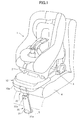
- FIG. 1 is a perspective view illustrating a child seat 1 according to the embodiment of the present invention in a state of being attached to a vehicle seat (hereinafter, also simply "seat") 4 of a vehicle while facing front.
- the child seat 1 includes a base 10 and a main body shell 2, and the base 10 supporting the main body shell 2 is secured to the vehicle seat 4 by an anchor mechanism 3 according to the ISOFIX standard.
- a support leg 30 attached to the lower surface of a base front end 10a via a rotational support 20 rises up on a vehicle body floor (hereinafter, also simply "floor”) 5 in front of the vehicle seat 4 and supports the base 10.
- a well-known detachable mechanism integrates the main body shell 2 with the base 10.
- the support leg 30 attached to the base front end 10a includes a leg support 31 made of synthetic resin.
- the support leg 30 can stably rise up by abutment of a disc-like bottom plate 31a of the leg support 31 with the surface of the vehicle body floor 5.
- a push button 32a of a button adjuster 32 protrudes in the upper portion of the front surface of the leg support 31.
- This push button 32a is a one-touch button that functions to adjust the length of a metal leg pipe 33, to be described later, accommodated in the leg support 31 of the support leg 30, to lock up the leg pipe 33 at a fixed position, and to unlock the leg pipe 33.
- the stability of the child seat 1 improves when the child seat 1 is installed by fixing the child seat 1 onto the seat 4 and raising up the support leg 30 on the floor 5. Due to this, even if the vehicle suddenly decelerates in a state, for example, in which a child is seated in the child seat 1 and the inertial force relative to the weight including the weight of the child seat 1 and the weight of the child acts on the child seat 1 , it is possible to ensure preventing the child seat 1 from rotating forward and to secure the safety of the child seated in the child seat 1 .
- FIG. 2A is a side view illustrating only the child seat 1 shown in FIG. 1 .
- the support leg 30 is collapsed into a base bottom (hereinafter, also simply "bottom") 10b of the base 10 at the rotational support 20 on the base front end 10a and accommodated in the lower portion of the base bottom 10b .
- a concave portion 11 (see FIG. 5C ) that can accommodate a part of a back surface of the leg support 31 is formed in the bottom 10b of the base 10 made of synthetic resin. A part of the back surface of the leg support 31 is accommodated in the concave portion 11.
- the child seat 1 in a state in which the front surface of the leg support 31 protrudes from the base bottom 10b, a user cannot closely attach the base 10 of the child seat 1 , onto the vehicle seat 4 differently from a state shown in FIG. 2B . Due to this, the user always needs to use the child seat 1 with the support leg 30 raised up and supported on the vehicle floor 5. Specifically, the child seat 1 according to the embodiment exhibits a secondary effect that the utilization rate of the support leg 30 can enhance.
- FIG. 2B is a side view of the child seat 1 in the same state as that shown in FIG. 1 .
- a portion of the front end 10a of the base 10 protruding from the front end of the vehicle seat 4 is slightly bent.
- the upper end of the support leg 30 is coupled to the front end 10a of the base 10 via the rotational support 20.
- FIG. 3 is a perspective view illustrating the base 10 with an upper surface 10c of the base 10 partially cut out so as to show the internal structure of the base 10 in a state of detaching the main body shell 2 of the child seat 1.
- a main frame 12 made of a metal pipe worked into a generally U shape in a plan view is provided in the base 10 along the longitudinal direction (an anterior-posterior direction) of the base 10.
- the main frame 12 is fixed in the base 10 by a fixing screw (not shown) and a frame holder 13 formed as a part of the base 10.
- the rotational support 20 is attached to a front end frame 12a of this main frame 12.
- the rotational support 20 includes a lock mechanism (the configuration of which will be described later) inside for locking and unlocking the leg pipe 33 when the support leg 30 rises up.
- the main frame 12 is made of a pipe and formed by integrally bending the front end frame 12a and stiffening frames 12b continuous to both sides of the front end frame 12a and extending in the longitudinal direction of the base 10. Due to this, by fixedly holding the main frame 12 in the entire interior of the base 10 , it is possible to secure the rigidity of the entire base 10. It is also possible to ensure that the entire child seat 1 is prevented from rotating forward via the support leg 30. Moreover, by attaching the rotational support 20 to a notch region of the base front end 10a, the base front end 10a has no protruding region. This can prevent the seated child from hitting his/her feet against such a protruding region.
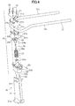
- FIG. 5A is a cross-sectional view illustrating the configuration of the rotational support 20 provided on the upper end of the leg pipe 33 held by the leg support 31. Constituent elements of the rotational support 31 and the relation among the constituent elements will be described with reference to the exploded perspective view of FIG. 4 .
- the constituent elements of the rotational support 20 are accommodated in an upper cover 21 and a lower cover 22 vertically separated and each made of a resin molded member.
- the lower cover 22 is the resin molded member obtained by integrally forming a guide pipe 22a, into which the leg pipe 33 held by the leg support 31 is inserted, with a rotational-member accommodation unit 22b located in the upper portion of the guide pipe 22a.
- the lower cover 22 accommodates therein a lock spring 23 externally fitted onto the leg pipe 33 and a pipe end holder 24 having a shaft 24a inserted into the upper end of the leg pipe 33.
- the shaft 24a of this pipe end holder 24 is fixed to the upper end of the leg pipe 33 by a steady pin 25.
- a lock pin 26 is inserted into a pin storage hole 24c formed in the pipe end holder 24 from below.
- the lock pin 26 is held by the pipe end holder 24 through a lower end flange 26a and the steady pin 25.
- the pipe end holder 24 is a resin molded member obtained by integrally forming the shaft 24a fixedly inserted into the leg pipe 33 and a frame holding plate support 24b.
- a frame holding plate 27 is a metal workpiece bent into a semicylindrical shape so as to have an inside diameter portion that can be closely attached to the main frame 12. Joint flanges 27b are formed on both ends of the frame holding plate 27. As shown in FIG. 4 , the frame holding plate 27 is configured so that an upper plate 27U and a lower plate 27L that are equally semicircular face each other to grasp and hold the front end frame 12a of the main frame 12.
- a lock pin holding hole (hereinafter, also simply “hole”) 27a through which the lock pin 26 slidably passes is formed at a central position of each of the semicircular upper and lower plates 27U and 27L.
- This lock pin holding hole 27a is subjected to curling in the direction of an outer surface so as to be able to guide the lock pin 26 sliding in this lock holding hole 27a and to hold the position of the lock pin 26.
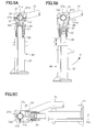
- FIG. 5A illustrates the rotational support 20 and the support leg 30 when the support leg 30 is raised up.
- the biasing force of the lock spring 23 accommodated in the rotational support 20 presses the pipe end holder 24 against the lower surface of the lower plate 27L.
- the lock pin 26 held by the pipe end holder 24 passes through a through-hole 14 (see FIG. 4 ) formed in the front end frame 12a.
- the upper end of the lock pin 26 passes through the lock pin holding hole 27a of the upper plate 27U and protrudes into a concave portion 21a formed in the upper cover 21.
- leg pipe 33 and the main frame 12 are locked together in a state in which the lock pin 26 integrated with the leg pipe 33 passes through the through-hole 14 of the main frame 12. Due to this, this ensures that the support leg 30 is held in the upright state as shown in FIG. 5A .
- the user pulls out the leg pipe 33 against the spring force of the lock spring 23 within the support leg 30 while grasping the leg support 31 of the leg pipe 33 as shown in FIG. 5B .
- the lock pin 26 integrated with the pipe end holder 24 is pulled out from the through-hole 14 (see FIG. 4 ) of the main frame 12.
- the locked state between the main frame 12 and the leg pipe 33 is released.
- the user can rotate the support leg 30 so as to collapse the support leg 30 in a collapsible direction (an X direction in FIG. 5B ).
- the support leg 30 is rotated up to the base bottom 10b of the child seat 1 and, as shown in FIG. 5C , the leg support 31 is fitted into the concave portion 11 formed in the base bottom 10b, thereby accommodating the support leg 30 in the lower portion of the base bottom 10b.
- the user pulls out the leg support 31 fitted into the concave portion 11 of the base bottom 10b and rotates the support leg 30 in an upright direction in this state.
- the support leg 30 is at an angle shown in FIG. 5A , the lock pin 26 biased by the lock spring 23 is inserted into the through-hole 14 of the front end frame 12a and the tip end of the lock pin 26 protrudes from the hole 27a of the upper plate 27U. The support leg 30 is thereby held upright.
- the user suffices to pull out the leg pipe 33 by as much as the predetermined amount and to rotate the leg pipe 33 while grasping the leg support 31.
- the user if the user is to raise up the support leg 30, the user pulls out the leg support 31 from within the concave portion 11 of the base bottom 10b and rotates the leg support 31 until the support leg 30 turns upright.
- the lock pin 26 acts to automatically lock the support leg 30.
- the user can easily collapse the support leg 30 only by pulling out and rotating the leg support 31 of the support leg 30 by one hand while supporting the main body of the child seat 1 by the other hand.
- the user can make the support leg 30 upright only by pulling out the leg support 31 that is accommodated in the concave portion 11 and rotating the leg support 31 so as to raise up the support leg 30.
- the leg support 31 of the support leg 30 is a synthetic resin molded member having the disc-like bottom plate 31a abutting on the floor 5 so as to accommodate and hold the second half of the leg pipe 33 and to surely support the support leg 30.
- a protrusion 34 that can accommodate a stopper pin 36 and an biasing spring 35 shown in FIG. 6 and an accommodation space 34a that can accommodate the button adjuster 32 are formed within the upper end of this leg support 31 (see FIG. 7A ).
- a plurality of height holding holes 33a is formed at predetermined positions on the outer circumference of the leg pipe 33 over an appropriate range at predetermined intervals in a height direction (see FIGS. 7A and 7B ).
- the button adjuster 32 is configured to include a ring body 32b functioning as an biasing and pressing member and the push button 32a actuated against the biasing force of the biasing spring 35.
- the ring body 32b has a long side S almost equal to the length that is the sum of the diameter of the leg pipe 33 and a length by which the push button 32a is pushed, and is formed into a generally D shape in a plan view.
- the stopper pin 36 includes a shaft having a diameter smaller than the inside diameter of the biasing spring 35 and a collar 36a holding one end of the biasing spring 35. The stopper pin 36 can position the leg pipe 33 by user's actuating the button adjuster 32 to insert a tip end 36b of the stopper pin 36 into one of the height holding holes 33a.
- the biasing spring 35 is accommodated first in the accommodation space 34a of the protrusion 34.
- the stopper pin 36 having the diameter smaller than the inside diameter of the biasing spring 35 is inserted into the biasing spring 35 so that the collar 36a of the stopper pin 36 contacts the biasing spring 35.
- the button adjuster 32 is inserted into a lateral opening 31d of the leg support 31 so that the push button 32a faces front.
- the leg pipe 33 is inserted from above into a leg retaining hole 31b .
- FIG. 7A is a side view illustrating the length adjustment mechanism when the leg pipe 33 is fixed.
- the height of the leg pipe 33 is defined by inserting the tip end 36b of the stopper pin 36 into one of the height holding holes 33a of the leg pipe 33 by the biasing force of the biasing spring 35 accommodated in the accommodation space 34a of the protrusion 34 of the leg support 31.
- the collar 36a of the stopper pin 36 presses the ring body 32b of the button adjuster 32 toward the stopper 33 to press the leg pipe 33 into one side of the interior of the leg retaining hole 31b of the leg support 31.
- the leg pipe 33 is thereby pressed in one direction along the long side S of the ring body 32b in the leg retaining hole 31b. Due to this, no clearance (play) is generated between the leg pipe 33 and the leg holding hold 31b, which can eliminate rattling of the leg pipe 33.
- the user suffices to push the push button 32a of the button adjuster 32 to force out the tip end 36b of the stopper pin 36 from the height holding hole 33a of the leg pipe 33.
- the leg pipe 33 can thereby freely slide in the height direction. If the user adjusts the height of leg pipe 33 so that the bottom plate 31a of the leg support 31 can abut on the vehicle body floor 5 and the stopper pin 36 is inserted into another height holding hole 33a, the stopper pin 36 acts to lock the leg pipe 33. Due to this, the user suffices to confirm whether the leg pipe 33 is locked and to set the support leg 30.
- the present invention has been described, taking the child seat 1 configured so that the main body shell 2 is separable from the base 10 as an example. Needless to say, even a child seat configured so that a base is integral with the bottom of a main body shell can exhibit the same effects as those of the child seat 1 according to the embodiment by attaching a support leg to the front end of the base via the above-stated rotational support.
Abstract
Description
- This application claims the benefit of Japanese Patent Application No.
2010-226535, filed on October 6, 2010 - This application relates generally to a child seat.
- There is conventionally known a child seat configured such that a main body shell is held on a relatively large base closely attached to the seat surface of a vehicle via a reclining mechanism. A child seat of this type often has a support leg provided on the front end of the base. By making this support leg rise up on a vehicle body floor in a state in which the child seat is secured onto a vehicle seat, it is possible to prevent the child seat from rotating forward during the frontal collision of the vehicle or the like. Therefore, the support leg can ensure the improved safety of the child seat.
- As disclosed in Unexamined Japanese Patent Application KOKAI Publication No.
2001-239868 - According to this child seat supporting device, if the child seat is to tilt forward around a restraint point at which a child is restrained (a fixed point at which the child is fastened by a seatbelt device) by an inertial force acting on the child seated in the child seat during the sudden deceleration of the vehicle or the like, a combination of the support leg and support arm in an L shape (or in the shape of a carpenter's square) in a lateral view of the vehicle supports the front end of the child seat. For example, the load acting on the child seat during the sudden deceleration of the vehicle or the like is transmitted from the support arm to the support leg and finally received by the vehicle body floor. This can prevent the child seat from tilting forward and sinking into the seat cushion of the vehicle seat.
- Meanwhile, each of the support leg and the support arm of the child seat supporting device disclosed in Unexamined Japanese Patent Application KOKAI Publication No.
2001-239868 2003-94994 - The extensible pipe support leg disclosed in Unexamined Japanese Patent Application KOKAI Publication No.
2003-94994 - Moreover, a support-leg-length adjustment mechanism is disclosed in Unexamined Japanese Patent Application KOKAI Publication No.
2003-94994 - It is an object of the present invention to provide a child seat capable of solving the problems of the conventional techniques stated above, and capable of facilitating collapsing and containing a support leg, raising up the support leg, and adjusting the length of the support leg.
- A child seat according to one aspect of the present invention is a child seat (1) attached to a vehicle, including: a frame body (12) which is contained in a base (10) supporting a main body seating and restraining a child, which stiffens the base (10), and which is fixed and disposed in the base (10) so that a front end is exposed from a notch formed in the base (10); a rotational support (20) attached to a site exposed at the base front end (10a) of the frame body (12) to be rotatable around the frame body (12), and containing a lock mechanism capable of being locked and unlocked at a predetermined angle with respect to the frame body (12); and a support leg (30) including a leg support (31) capable of adjusting and holding a leg portion coupled to the rotational support (20) at a predetermined length, characterized in that the base (10) is fixed onto a vehicle seat (4), the support leg (30) is rotated around the rotational support (20) and adjusted to have a predetermined length at a base front end position, and the base (10) is stably held by abutting a bottom plate of the leg support on a vehicle body floor (5).
- It is preferable that the frame body (12) comprises a pipe material that is processed substantially into u-shape including a front end frame (12a) located on the front end of the base (10), and a hardened frame (12b) connecting both sides of the front end frame (12a) and extending in a longitudinal direction of the base (10), and the rotational support (20) is rotatably attached to the front end frame (12a).
- It is preferable that the lock mechanism locks by inserting a lock pin (26) biased by a biaser contained in inner portion into a through-hole (14) formed in the frame body (12), and unlocks by pulling out the leg portion of the support leg (30) from the rotational support (20) by a predetermined distance against the biaser.
- It is preferable that a concave portion (11) capable of containing a part of the leg support (31) with the leg portion of the support leg (30) pulled out is formed in a bottom surface of the base (10).
- It is preferable that the leg support (31) includes a leg retaining hole (31b), into which the leg portion is slidably inserted, and includes a biasing and pressing member pressing the leg portion against an inner side surface of the leg retaining hole (31) while the leg portion is maintained at a predetermined length.
- According to the present invention, it is possible to perform an operation for collapsing the support leg attached to the base of the child seat and an operation for raising up the support leg by one hand, and to easily adjust the length of the support leg according to a vehicle body floor.
- A more complete understanding of this application can be obtained when the following detailed description is considered in conjunction with the following drawings, in which:
-
FIG. 1 is an overall perspective view illustrating a child seat according to an embodiment of the present invention in a state of being attached to a vehicle seat; -
FIG. 2A is a side view illustrating the child seat according to the embodiment in a state of collapsing a support leg; -
FIG. 2B is a side view illustrating the child seat according to the embodiment in a state of being attached to the vehicle seat; -
FIG. 3 is a perspective view of a base of the child seat shown inFIG. 1 with the upper surface of the base partially cut out so as to show the structure of a main frame in the base; -
FIG. 4 is an exploded perspective view illustrating the main frame and the rotational support of the support leg rotatably attached to the main frame in an exploded manner; -
FIG. 5A illustrates the rotational support and the support leg when the support leg is raised up; -
FIG. 5B illustrates the rotational support and the support leg when the support leg is collapsed; -
FIG. 5C illustrates the rotational support and the support leg when the support leg is accommodated in a lower portion of the bottom of the base; -
FIG. 6 is an exploded perspective view illustrating the configuration of a lock mechanism of a support-leg length adjustment unit in an exploded manner; -
FIG. 7A is an enlarged cross-sectional view for describing operation performed by the lock mechanism shown inFIG. 6 ; and -
FIG. 7B is an enlarged cross-sectional view for describing operation performed by the lock mechanism shown inFIG. 6 . - A child seat according to a preferred embodiment of the present invention will be described hereinafter with reference to the accompanying drawings.
-
FIG. 1 is a perspective view illustrating achild seat 1 according to the embodiment of the present invention in a state of being attached to a vehicle seat (hereinafter, also simply "seat") 4 of a vehicle while facing front. In the embodiment, thechild seat 1 includes abase 10 and amain body shell 2, and thebase 10 supporting themain body shell 2 is secured to thevehicle seat 4 by ananchor mechanism 3 according to the ISOFIX standard. As shown inFIG. 1 , asupport leg 30 attached to the lower surface of abase front end 10a via arotational support 20 rises up on a vehicle body floor (hereinafter, also simply "floor") 5 in front of thevehicle seat 4 and supports thebase 10. In the embodiment, a well-known detachable mechanism (not shown) integrates themain body shell 2 with thebase 10. - As shown in
FIG. 1 , thesupport leg 30 attached to thebase front end 10a includes aleg support 31 made of synthetic resin. Thesupport leg 30 can stably rise up by abutment of a disc-like bottom plate 31a of theleg support 31 with the surface of thevehicle body floor 5. Apush button 32a of a button adjuster 32 (to be described later) protrudes in the upper portion of the front surface of theleg support 31. Thispush button 32a is a one-touch button that functions to adjust the length of ametal leg pipe 33, to be described later, accommodated in theleg support 31 of thesupport leg 30, to lock up theleg pipe 33 at a fixed position, and to unlock theleg pipe 33. - The stability of the
child seat 1 improves when thechild seat 1 is installed by fixing thechild seat 1 onto theseat 4 and raising up thesupport leg 30 on thefloor 5. Due to this, even if the vehicle suddenly decelerates in a state, for example, in which a child is seated in thechild seat 1 and the inertial force relative to the weight including the weight of thechild seat 1 and the weight of the child acts on thechild seat 1, it is possible to ensure preventing thechild seat 1 from rotating forward and to secure the safety of the child seated in thechild seat 1. -
FIG. 2A is a side view illustrating only thechild seat 1 shown inFIG. 1 . As shown inFIG. 2A , if thechild seat 1 is detached from thevehicle seat 4, then thesupport leg 30 is collapsed into a base bottom (hereinafter, also simply "bottom") 10b of thebase 10 at therotational support 20 on thebase front end 10a and accommodated in the lower portion of thebase bottom 10b. A concave portion 11 (seeFIG. 5C ) that can accommodate a part of a back surface of theleg support 31 is formed in the bottom 10b of the base 10 made of synthetic resin. A part of the back surface of theleg support 31 is accommodated in theconcave portion 11. At this time, as shown inFIG. 2A , a part of the front surface of theleg support 31 protrudes from thebase bottom 10b. Accordingly, in a state in which the front surface of theleg support 31 protrudes from thebase bottom 10b, a user cannot closely attach thebase 10 of thechild seat 1 , onto thevehicle seat 4 differently from a state shown inFIG. 2B . Due to this, the user always needs to use thechild seat 1 with thesupport leg 30 raised up and supported on thevehicle floor 5. Specifically, thechild seat 1 according to the embodiment exhibits a secondary effect that the utilization rate of thesupport leg 30 can enhance. -
FIG. 2B is a side view of thechild seat 1 in the same state as that shown inFIG. 1 . As shown inFIG. 2B , a portion of thefront end 10a of the base 10 protruding from the front end of thevehicle seat 4 is slightly bent. The upper end of thesupport leg 30 is coupled to thefront end 10a of thebase 10 via therotational support 20. By configuring the base 10 into such a shape, it is possible to secure a wide space at the feet of the seated child. -
FIG. 3 is a perspective view illustrating the base 10 with anupper surface 10c of the base 10 partially cut out so as to show the internal structure of the base 10 in a state of detaching themain body shell 2 of thechild seat 1. As shown inFIG. 3 , amain frame 12 made of a metal pipe worked into a generally U shape in a plan view is provided in thebase 10 along the longitudinal direction (an anterior-posterior direction) of thebase 10. Themain frame 12 is fixed in thebase 10 by a fixing screw (not shown) and aframe holder 13 formed as a part of thebase 10. Furthermore, therotational support 20 is attached to afront end frame 12a of thismain frame 12. Therotational support 20 includes a lock mechanism (the configuration of which will be described later) inside for locking and unlocking theleg pipe 33 when thesupport leg 30 rises up. - The
main frame 12 is made of a pipe and formed by integrally bending thefront end frame 12a and stiffeningframes 12b continuous to both sides of thefront end frame 12a and extending in the longitudinal direction of thebase 10. Due to this, by fixedly holding themain frame 12 in the entire interior of thebase 10, it is possible to secure the rigidity of theentire base 10. It is also possible to ensure that theentire child seat 1 is prevented from rotating forward via thesupport leg 30. Moreover, by attaching therotational support 20 to a notch region of the basefront end 10a, the basefront end 10a has no protruding region. This can prevent the seated child from hitting his/her feet against such a protruding region. - The configuration of the
rotational support 20 coupled to thefront end frame 12a of themain frame 12 will now be described with reference toFIGS. 4 and5A . -
FIG. 5A is a cross-sectional view illustrating the configuration of therotational support 20 provided on the upper end of theleg pipe 33 held by theleg support 31. Constituent elements of therotational support 31 and the relation among the constituent elements will be described with reference to the exploded perspective view ofFIG. 4 . - As shown in
FIG. 4 , the constituent elements of therotational support 20 are accommodated in anupper cover 21 and alower cover 22 vertically separated and each made of a resin molded member. Thelower cover 22 is the resin molded member obtained by integrally forming aguide pipe 22a, into which theleg pipe 33 held by theleg support 31 is inserted, with a rotational-member accommodation unit 22b located in the upper portion of theguide pipe 22a. Thelower cover 22 accommodates therein alock spring 23 externally fitted onto theleg pipe 33 and apipe end holder 24 having ashaft 24a inserted into the upper end of theleg pipe 33. Theshaft 24a of thispipe end holder 24 is fixed to the upper end of theleg pipe 33 by asteady pin 25. Alock pin 26 is inserted into apin storage hole 24c formed in thepipe end holder 24 from below. Thelock pin 26 is held by thepipe end holder 24 through alower end flange 26a and thesteady pin 25. - The
pipe end holder 24 is a resin molded member obtained by integrally forming theshaft 24a fixedly inserted into theleg pipe 33 and a frame holdingplate support 24b. A frame holding plate 27 is a metal workpiece bent into a semicylindrical shape so as to have an inside diameter portion that can be closely attached to themain frame 12.Joint flanges 27b are formed on both ends of the frame holding plate 27. As shown inFIG. 4 , the frame holding plate 27 is configured so that anupper plate 27U and alower plate 27L that are equally semicircular face each other to grasp and hold thefront end frame 12a of themain frame 12. A lock pin holding hole (hereinafter, also simply "hole") 27a through which thelock pin 26 slidably passes is formed at a central position of each of the semicircular upper andlower plates pin holding hole 27a is subjected to curling in the direction of an outer surface so as to be able to guide thelock pin 26 sliding in thislock holding hole 27a and to hold the position of thelock pin 26. - These constituent elements of the
rotational support 20 are attached to thelower cover 22 and theleg pipe 33 and covered with theupper cover 21 from above so as to cover up the entire constituent elements. Theupper cover 21 and thelower cover 22 are coupled byjoint bolts 28, thereby constituting therotational support 20. - Operation performed by the
support leg 30 and therotational support 20 when thesupport leg 30 is raised up or collapsed will be described with reference toFIGS. 5A to 5C. FIG. 5A illustrates therotational support 20 and thesupport leg 30 when thesupport leg 30 is raised up. In this upright state, the biasing force of thelock spring 23 accommodated in therotational support 20 presses thepipe end holder 24 against the lower surface of thelower plate 27L. At this time, thelock pin 26 held by thepipe end holder 24 passes through a through-hole 14 (seeFIG. 4 ) formed in thefront end frame 12a. Furthermore, the upper end of thelock pin 26 passes through the lockpin holding hole 27a of theupper plate 27U and protrudes into aconcave portion 21a formed in theupper cover 21. Accordingly, theleg pipe 33 and themain frame 12 are locked together in a state in which thelock pin 26 integrated with theleg pipe 33 passes through the through-hole 14 of themain frame 12. Due to this, this ensures that thesupport leg 30 is held in the upright state as shown inFIG. 5A . - To collapse the
support leg 30 of thechild seat 1 detached from thevehicle seat 4, the user pulls out theleg pipe 33 against the spring force of thelock spring 23 within thesupport leg 30 while grasping theleg support 31 of theleg pipe 33 as shown inFIG. 5B . Specifically, when the user pulls theleg pipe 33 by a length L at which thelock spring 23 is fully compressed, thelock pin 26 integrated with thepipe end holder 24 is pulled out from the through-hole 14 (seeFIG. 4 ) of themain frame 12. At this time, the locked state between themain frame 12 and theleg pipe 33 is released. Due to this, with the tip end of thelock pin 26 held by the curled portion of thelower plate 27L and abutting on the outer circumference of thefront end frame 12a, the user can rotate thesupport leg 30 so as to collapse thesupport leg 30 in a collapsible direction (an X direction inFIG. 5B ). - Furthermore, the
support leg 30 is rotated up to thebase bottom 10b of thechild seat 1 and, as shown inFIG. 5C , theleg support 31 is fitted into theconcave portion 11 formed in thebase bottom 10b, thereby accommodating thesupport leg 30 in the lower portion of thebase bottom 10b. - On the other hand, to raise up the
support leg 30, the user pulls out theleg support 31 fitted into theconcave portion 11 of thebase bottom 10b and rotates thesupport leg 30 in an upright direction in this state. When thesupport leg 30 is at an angle shown inFIG. 5A , thelock pin 26 biased by thelock spring 23 is inserted into the through-hole 14 of thefront end frame 12a and the tip end of thelock pin 26 protrudes from thehole 27a of theupper plate 27U. Thesupport leg 30 is thereby held upright. - In this way, if the user is to collapse the
support leg 30, the user suffices to pull out theleg pipe 33 by as much as the predetermined amount and to rotate theleg pipe 33 while grasping theleg support 31. On the other hand, if the user is to raise up thesupport leg 30, the user pulls out theleg support 31 from within theconcave portion 11 of thebase bottom 10b and rotates theleg support 31 until thesupport leg 30 turns upright. By doing so, thelock pin 26 acts to automatically lock thesupport leg 30. In this way, the user can easily collapse thesupport leg 30 only by pulling out and rotating theleg support 31 of thesupport leg 30 by one hand while supporting the main body of thechild seat 1 by the other hand. Furthermore, the user can make thesupport leg 30 upright only by pulling out theleg support 31 that is accommodated in theconcave portion 11 and rotating theleg support 31 so as to raise up thesupport leg 30. - The configuration of a length adjustment mechanism for the
leg pipe 33 incorporated in theleg support 31 of thesupport leg 30 will now be described with reference toFIGS. 6 ,7A, and 7B . - As stated, the
leg support 31 of thesupport leg 30 is a synthetic resin molded member having the disc-like bottom plate 31a abutting on thefloor 5 so as to accommodate and hold the second half of theleg pipe 33 and to surely support thesupport leg 30. Aprotrusion 34 that can accommodate astopper pin 36 and an biasingspring 35 shown inFIG. 6 and anaccommodation space 34a that can accommodate thebutton adjuster 32 are formed within the upper end of this leg support 31 (seeFIG. 7A ). Moreover, a plurality ofheight holding holes 33a is formed at predetermined positions on the outer circumference of theleg pipe 33 over an appropriate range at predetermined intervals in a height direction (seeFIGS. 7A and 7B ). - As shown in
FIG. 6 , thebutton adjuster 32 is configured to include aring body 32b functioning as an biasing and pressing member and thepush button 32a actuated against the biasing force of the biasingspring 35. Thering body 32b has a long side S almost equal to the length that is the sum of the diameter of theleg pipe 33 and a length by which thepush button 32a is pushed, and is formed into a generally D shape in a plan view. Thestopper pin 36 includes a shaft having a diameter smaller than the inside diameter of the biasingspring 35 and acollar 36a holding one end of the biasingspring 35. Thestopper pin 36 can position theleg pipe 33 by user's actuating thebutton adjuster 32 to insert atip end 36b of thestopper pin 36 into one of theheight holding holes 33a. - If these components are to be assembled together, the biasing
spring 35 is accommodated first in theaccommodation space 34a of theprotrusion 34. Next, thestopper pin 36 having the diameter smaller than the inside diameter of the biasingspring 35 is inserted into the biasingspring 35 so that thecollar 36a of thestopper pin 36 contacts the biasingspring 35. After accommodating the biasingspring 35 and thestopper pin 36 in theaccommodation space 34a, thebutton adjuster 32 is inserted into alateral opening 31d of theleg support 31 so that thepush button 32a faces front. Thereafter, theleg pipe 33 is inserted from above into aleg retaining hole 31b. -
FIG. 7A is a side view illustrating the length adjustment mechanism when theleg pipe 33 is fixed. As shown inFIG. 7A , the height of theleg pipe 33 is defined by inserting thetip end 36b of thestopper pin 36 into one of theheight holding holes 33a of theleg pipe 33 by the biasing force of the biasingspring 35 accommodated in theaccommodation space 34a of theprotrusion 34 of theleg support 31. Furthermore, thecollar 36a of thestopper pin 36 presses thering body 32b of thebutton adjuster 32 toward thestopper 33 to press theleg pipe 33 into one side of the interior of theleg retaining hole 31b of theleg support 31. Theleg pipe 33 is thereby pressed in one direction along the long side S of thering body 32b in theleg retaining hole 31b. Due to this, no clearance (play) is generated between theleg pipe 33 and theleg holding hold 31b, which can eliminate rattling of theleg pipe 33. - To adjust the height of the
leg pipe 33 while theleg pipe 33 is fixed as shown inFIG. 7A , the user suffices to push thepush button 32a of thebutton adjuster 32 to force out thetip end 36b of thestopper pin 36 from theheight holding hole 33a of theleg pipe 33. Theleg pipe 33 can thereby freely slide in the height direction. If the user adjusts the height ofleg pipe 33 so that thebottom plate 31a of theleg support 31 can abut on thevehicle body floor 5 and thestopper pin 36 is inserted into anotherheight holding hole 33a, thestopper pin 36 acts to lock theleg pipe 33. Due to this, the user suffices to confirm whether theleg pipe 33 is locked and to set thesupport leg 30. - The present invention has been described, taking the
child seat 1 configured so that themain body shell 2 is separable from the base 10 as an example. Needless to say, even a child seat configured so that a base is integral with the bottom of a main body shell can exhibit the same effects as those of thechild seat 1 according to the embodiment by attaching a support leg to the front end of the base via the above-stated rotational support. - Specifically, the present invention is not limited to the above-stated embodiment and it should be apparent that the preferred embodiment may be modified in arrangement and detail without departing from the principles disclosed herein and that it is intended that the application be construed as including all such modifications and variations insofar as they come within the spirit and scope of the subject matter disclosed herein.
Claims (5)
- A child seat (1) attached to a vehicle, characterized by comprising:a frame body (12) which is contained in a base (10) supporting a main body seating and restraining a child, which stiffens the base (10), and which is fixed and disposed in the base (10) so that a front end is exposed from a notch formed in the base (10);a rotational support (20) attached to a site exposed at the base front end (10a) of the frame body (12) to be rotatable around the frame body (12), and containing a lock mechanism capable of being locked and unlocked at a predetermined angle with respect to the frame body (12); anda support leg (30) including a leg support (31) capable of adjusting and holding a leg portion coupled to the rotational support (20) at a predetermined length, characterized in thatthe base (10) is fixed onto a vehicle seat (4), the support leg (30) is rotated around the rotational support (20) and adjusted to have a predetermined length at a base front end position, and the base (10) is stably held by abutting a bottom plate of the leg support on a vehicle body floor (5).
- The child seat (1) according to claim 1, characterized in that
the frame body (12) comprises a pipe material that is processed substantially into u-shape including a front end frame (12a) located on the front end of the base (10), and a hardened frame (12b) connecting both sides of the front end frame (12a) and extending in a longitudinal direction of the base (10), and the rotational support (20) is rotatably attached to the front end frame (12a). - The child seat (1) according to claim 1 or 2, characterized in that
the lock mechanism locks by inserting a lock pin (26) biased by a biaser contained in inner portion into a through-hole (14) formed in the frame body (12), and unlocks by pulling out the leg portion of the support leg (30) from the rotational support (20) by a predetermined distance against the biaser. - The child seat (1) according to claim 3, characterized in that
a concave portion (11) capable of containing a part of the leg support (31) with the leg portion of the support leg (30) pulled out is formed in a bottom surface of the base (10). - The child seat (1) according to any one of claims 1 to 4, characterized in that
the leg support (31) includes a leg retaining hole (31b), into which the leg portion is slidably inserted, and includes a biasing and pressing member pressing the leg portion against an inner side surface of the leg retaining hole (31) while the leg portion is maintained at a predetermined length.
Applications Claiming Priority (1)
| Application Number | Priority Date | Filing Date | Title |
|---|---|---|---|
| JP2010226535A JP5596485B2 (en) | 2010-10-06 | 2010-10-06 | child seat |
Publications (3)
| Publication Number | Publication Date |
|---|---|
| EP2439102A2 true EP2439102A2 (en) | 2012-04-11 |
| EP2439102A3 EP2439102A3 (en) | 2017-11-29 |
| EP2439102B1 EP2439102B1 (en) | 2020-04-01 |
Family
ID=44862280
Family Applications (1)
| Application Number | Title | Priority Date | Filing Date |
|---|---|---|---|
| EP11008064.5A Active EP2439102B1 (en) | 2010-10-06 | 2011-10-05 | Child seat |
Country Status (4)
| Country | Link |
|---|---|
| EP (1) | EP2439102B1 (en) |
| JP (1) | JP5596485B2 (en) |
| KR (1) | KR20120035880A (en) |
| CN (1) | CN102442238B (en) |
Cited By (7)
| Publication number | Priority date | Publication date | Assignee | Title |
|---|---|---|---|---|
| GB2492201A (en) * | 2011-06-21 | 2012-12-26 | Bp Childrens Prod Hk Co Ltd | Safety seat device including support leg unit |
| US9102249B2 (en) | 2012-06-07 | 2015-08-11 | Bp Children's Products Hk Co., Limited | Child safety seat |
| CN104875636A (en) * | 2015-06-12 | 2015-09-02 | 上海翼锐汽车科技有限公司 | Light supporting leg of child seat |
| CN105313728A (en) * | 2014-06-24 | 2016-02-10 | 爱普力卡幼儿产品合同会社 | Child seat |
| CN107839554A (en) * | 2016-09-19 | 2018-03-27 | 珠海弘点科技有限公司 | Children's seat leg structure and children's seat support base |
| EP3315357A1 (en) * | 2016-11-01 | 2018-05-02 | M. Myung Joo LEE | Position adjusting device of footrest for car seat |
| CN110281821A (en) * | 2019-06-27 | 2019-09-27 | 宁波宝贝第一母婴用品有限公司 | A kind of child safety seat supporting leg locked automatically and its folding method |
Families Citing this family (13)
| Publication number | Priority date | Publication date | Assignee | Title |
|---|---|---|---|---|
| CN102582479B (en) * | 2011-01-06 | 2014-11-05 | 明门香港股份有限公司 | Support device |
| JP6230872B2 (en) * | 2012-12-11 | 2017-11-15 | アップリカ・チルドレンズプロダクツ合同会社 | Infant container |
| CN104290618B (en) * | 2013-07-17 | 2017-03-01 | 明门香港股份有限公司 | Support feet guiding mechanism and support feet |
| JP6420112B2 (en) * | 2014-10-14 | 2018-11-07 | 株式会社カーメイト | Child seat support device |
| CN105799559B (en) * | 2014-12-31 | 2018-04-13 | 明门香港股份有限公司 | Height regulating mechanism and the infant carrier device with this height regulating mechanism |
| JP6590673B2 (en) * | 2015-12-10 | 2019-10-16 | アップリカ・チルドレンズプロダクツ合同会社 | child seat |
| KR101850833B1 (en) * | 2016-09-13 | 2018-05-31 | 주식회사 쁘레베베 | Support leg and safety car seat for infant using the same |
| US10272804B2 (en) * | 2016-11-08 | 2019-04-30 | Wonderland Switzerland Ag | Child safety seat |
| NO343527B1 (en) * | 2017-03-27 | 2019-04-01 | Torgersen Hans & Soenn | Child safety seat for a vehicle |
| JP6850197B2 (en) * | 2017-05-29 | 2021-03-31 | ニューウェルブランズ・ジャパン合同会社 | child seat |
| CN109305072B (en) * | 2017-07-26 | 2024-01-30 | 珠海阳光儿童用品有限公司 | Child safety seat support |
| KR102224094B1 (en) * | 2019-10-28 | 2021-03-08 | 주식회사 서연이화 | Tether anchor assembly for child seat fixture |
| CN113212302B (en) * | 2021-04-20 | 2023-04-18 | 宁波环球娃娃婴童用品股份有限公司 | Installation adjustment detection method and system for child safety seat |
Citations (3)
| Publication number | Priority date | Publication date | Assignee | Title |
|---|---|---|---|---|
| JP2001239868A (en) | 2000-03-01 | 2001-09-04 | Tokai Rika Co Ltd | Child seat supporting device |
| JP2003094994A (en) | 2001-09-25 | 2003-04-03 | Combi Corp | Support leg device of child seat |
| JP2010226535A (en) | 2009-03-24 | 2010-10-07 | Fuji Xerox Co Ltd | Controller, image forming apparatus and program |
Family Cites Families (9)
| Publication number | Priority date | Publication date | Assignee | Title |
|---|---|---|---|---|
| JP2001107925A (en) * | 1999-10-12 | 2001-04-17 | Takano Co Ltd | Expansion mechanism and light vehicle using it |
| US6817665B2 (en) * | 2001-07-26 | 2004-11-16 | Graco Children's Products Inc. | Seat base with load leg |
| US20080303321A1 (en) * | 2004-05-08 | 2008-12-11 | Britax Excelsior Limited | Base for a Child Safety Support |
| GB0420414D0 (en) * | 2004-09-14 | 2004-10-20 | Barker Derrick | Child car seat |
| NL1028788C2 (en) * | 2005-04-18 | 2006-10-20 | Maxi Miliaan Bv | Undercarriage as well as child vehicle seat provided with such an undercarriage. |
| GB0510313D0 (en) * | 2005-05-20 | 2005-06-29 | Britax Childcare Ltd | Child safety seat |
| EP1927502B1 (en) * | 2006-11-28 | 2009-09-09 | Wonderland Nurserygoods Co., Ltd. | Child vehicle safety seat |
| EP1970247A1 (en) * | 2007-03-15 | 2008-09-17 | Team-Tex | Device for mounting a child seat in a car and a child seat |
| CN201511847U (en) * | 2009-10-11 | 2010-06-23 | 林江娟 | Motor vehicle seat chair with ISOFIX joint for children |
-
2010
- 2010-10-06 JP JP2010226535A patent/JP5596485B2/en not_active Expired - Fee Related
-
2011
- 2011-09-29 CN CN201110305691.2A patent/CN102442238B/en not_active Expired - Fee Related
- 2011-10-05 EP EP11008064.5A patent/EP2439102B1/en active Active
- 2011-10-05 KR KR1020110101057A patent/KR20120035880A/en not_active Application Discontinuation
Patent Citations (3)
| Publication number | Priority date | Publication date | Assignee | Title |
|---|---|---|---|---|
| JP2001239868A (en) | 2000-03-01 | 2001-09-04 | Tokai Rika Co Ltd | Child seat supporting device |
| JP2003094994A (en) | 2001-09-25 | 2003-04-03 | Combi Corp | Support leg device of child seat |
| JP2010226535A (en) | 2009-03-24 | 2010-10-07 | Fuji Xerox Co Ltd | Controller, image forming apparatus and program |
Cited By (12)
| Publication number | Priority date | Publication date | Assignee | Title |
|---|---|---|---|---|
| GB2492201A (en) * | 2011-06-21 | 2012-12-26 | Bp Childrens Prod Hk Co Ltd | Safety seat device including support leg unit |
| GB2492201B (en) * | 2011-06-21 | 2018-06-13 | Bp Childrens Products Hk Co Ltd | Safety seat device |
| US9102249B2 (en) | 2012-06-07 | 2015-08-11 | Bp Children's Products Hk Co., Limited | Child safety seat |
| DE102013007707B4 (en) * | 2012-06-07 | 2017-02-09 | Bp Children's Products Hk Co., Limited | Child safety seat |
| CN105313728A (en) * | 2014-06-24 | 2016-02-10 | 爱普力卡幼儿产品合同会社 | Child seat |
| CN105313728B (en) * | 2014-06-24 | 2019-12-13 | 爱普力卡幼儿产品合同会社 | Children's seat |
| CN104875636A (en) * | 2015-06-12 | 2015-09-02 | 上海翼锐汽车科技有限公司 | Light supporting leg of child seat |
| CN104875636B (en) * | 2015-06-12 | 2017-04-12 | 上海翼锐汽车科技有限公司 | Light supporting leg of child seat |
| CN107839554A (en) * | 2016-09-19 | 2018-03-27 | 珠海弘点科技有限公司 | Children's seat leg structure and children's seat support base |
| EP3315357A1 (en) * | 2016-11-01 | 2018-05-02 | M. Myung Joo LEE | Position adjusting device of footrest for car seat |
| US10286827B2 (en) | 2016-11-01 | 2019-05-14 | Myung Joo LEE | Position adjusting device of footrest for car seat |
| CN110281821A (en) * | 2019-06-27 | 2019-09-27 | 宁波宝贝第一母婴用品有限公司 | A kind of child safety seat supporting leg locked automatically and its folding method |
Also Published As
| Publication number | Publication date |
|---|---|
| EP2439102B1 (en) | 2020-04-01 |
| EP2439102A3 (en) | 2017-11-29 |
| JP5596485B2 (en) | 2014-09-24 |
| JP2012076717A (en) | 2012-04-19 |
| CN102442238B (en) | 2015-09-16 |
| KR20120035880A (en) | 2012-04-16 |
| CN102442238A (en) | 2012-05-09 |
Similar Documents
| Publication | Publication Date | Title |
|---|---|---|
| EP2439102B1 (en) | Child seat | |
| CN111278677B (en) | Child seat system comprising a seat element and a base mountable on a vehicle seat | |
| EP3165400B1 (en) | Child safety seat | |
| JP5778025B2 (en) | Webbing take-up device | |
| EP2616271B1 (en) | Child seat | |
| US8567862B2 (en) | Child safety seat assembly | |
| US5779319A (en) | Child seat retractor | |
| US9022472B2 (en) | Child safety seat | |
| US8556344B2 (en) | Child safety seat assembly | |
| US10023089B2 (en) | Headrest | |
| EP2308715A1 (en) | Child seat | |
| US20020145319A1 (en) | Child car seat | |
| EP2901894B1 (en) | Head rest | |
| US8978214B2 (en) | Seatbelt buckle apparatus | |
| EP2308716A1 (en) | Child seat | |
| JP5680975B2 (en) | Child seat belt lock device and child seat | |
| US8118360B2 (en) | Vehicle seat | |
| JP2001504774A (en) | Device for detachably attaching objects to mobile units | |
| WO2011079350A1 (en) | Pivotable infant car seat | |
| EP1816929B1 (en) | Infant swing seat | |
| US5690382A (en) | Adjustable child-restraint shield | |
| US9067758B2 (en) | Webbing take-up device | |
| JP2011031847A (en) | Buckle device for seat belt | |
| JP5619377B2 (en) | Buckle structure of vehicle seat | |
| JPH11165569A (en) | Reclining seat |
Legal Events
| Date | Code | Title | Description |
|---|---|---|---|
| AK | Designated contracting states |
Kind code of ref document: A2 Designated state(s): AL AT BE BG CH CY CZ DE DK EE ES FI FR GB GR HR HU IE IS IT LI LT LU LV MC MK MT NL NO PL PT RO RS SE SI SK SM TR |
|
| AX | Request for extension of the european patent |
Extension state: BA ME |
|
| PUAI | Public reference made under article 153(3) epc to a published international application that has entered the european phase |
Free format text: ORIGINAL CODE: 0009012 |
|
| PUAL | Search report despatched |
Free format text: ORIGINAL CODE: 0009013 |
|
| AK | Designated contracting states |
Kind code of ref document: A3 Designated state(s): AL AT BE BG CH CY CZ DE DK EE ES FI FR GB GR HR HU IE IS IT LI LT LU LV MC MK MT NL NO PL PT RO RS SE SI SK SM TR |
|
| AX | Request for extension of the european patent |
Extension state: BA ME |
|
| RIC1 | Information provided on ipc code assigned before grant |
Ipc: B60N 2/28 20060101AFI20171020BHEP Ipc: B60N 2/26 20060101ALI20171020BHEP |
|
| STAA | Information on the status of an ep patent application or granted ep patent |
Free format text: STATUS: REQUEST FOR EXAMINATION WAS MADE |
|
| 17P | Request for examination filed |
Effective date: 20180207 |
|
| RBV | Designated contracting states (corrected) |
Designated state(s): AL AT BE BG CH CY CZ DE DK EE ES FI FR GB GR HR HU IE IS IT LI LT LU LV MC MK MT NL NO PL PT RO RS SE SI SK SM TR |
|
| RAP1 | Party data changed (applicant data changed or rights of an application transferred) |
Owner name: JOYSON SAFETY SYSTEMS JAPAN K.K. |
|
| GRAP | Despatch of communication of intention to grant a patent |
Free format text: ORIGINAL CODE: EPIDOSNIGR1 |
|
| STAA | Information on the status of an ep patent application or granted ep patent |
Free format text: STATUS: GRANT OF PATENT IS INTENDED |
|
| INTG | Intention to grant announced |
Effective date: 20191126 |
|
| RIN1 | Information on inventor provided before grant (corrected) |
Inventor name: SAKUMOTO, MASAYUKI |
|
| GRAS | Grant fee paid |
Free format text: ORIGINAL CODE: EPIDOSNIGR3 |
|
| GRAA | (expected) grant |
Free format text: ORIGINAL CODE: 0009210 |
|
| STAA | Information on the status of an ep patent application or granted ep patent |
Free format text: STATUS: THE PATENT HAS BEEN GRANTED |
|
| AK | Designated contracting states |
Kind code of ref document: B1 Designated state(s): AL AT BE BG CH CY CZ DE DK EE ES FI FR GB GR HR HU IE IS IT LI LT LU LV MC MK MT NL NO PL PT RO RS SE SI SK SM TR |
|
| REG | Reference to a national code |
Ref country code: GB Ref legal event code: FG4D |
|
| REG | Reference to a national code |
Ref country code: CH Ref legal event code: EP Ref country code: AT Ref legal event code: REF Ref document number: 1250936 Country of ref document: AT Kind code of ref document: T Effective date: 20200415 |
|
| REG | Reference to a national code |
Ref country code: DE Ref legal event code: R096 Ref document number: 602011065928 Country of ref document: DE |
|
| REG | Reference to a national code |
Ref country code: IE Ref legal event code: FG4D |
|
| PG25 | Lapsed in a contracting state [announced via postgrant information from national office to epo] |
Ref country code: BG Free format text: LAPSE BECAUSE OF FAILURE TO SUBMIT A TRANSLATION OF THE DESCRIPTION OR TO PAY THE FEE WITHIN THE PRESCRIBED TIME-LIMIT Effective date: 20200701 |
|
| REG | Reference to a national code |
Ref country code: NL Ref legal event code: MP Effective date: 20200401 |
|
| REG | Reference to a national code |
Ref country code: LT Ref legal event code: MG4D |
|
| PG25 | Lapsed in a contracting state [announced via postgrant information from national office to epo] |
Ref country code: LT Free format text: LAPSE BECAUSE OF FAILURE TO SUBMIT A TRANSLATION OF THE DESCRIPTION OR TO PAY THE FEE WITHIN THE PRESCRIBED TIME-LIMIT Effective date: 20200401 Ref country code: FI Free format text: LAPSE BECAUSE OF FAILURE TO SUBMIT A TRANSLATION OF THE DESCRIPTION OR TO PAY THE FEE WITHIN THE PRESCRIBED TIME-LIMIT Effective date: 20200401 Ref country code: GR Free format text: LAPSE BECAUSE OF FAILURE TO SUBMIT A TRANSLATION OF THE DESCRIPTION OR TO PAY THE FEE WITHIN THE PRESCRIBED TIME-LIMIT Effective date: 20200702 Ref country code: IS Free format text: LAPSE BECAUSE OF FAILURE TO SUBMIT A TRANSLATION OF THE DESCRIPTION OR TO PAY THE FEE WITHIN THE PRESCRIBED TIME-LIMIT Effective date: 20200801 Ref country code: NO Free format text: LAPSE BECAUSE OF FAILURE TO SUBMIT A TRANSLATION OF THE DESCRIPTION OR TO PAY THE FEE WITHIN THE PRESCRIBED TIME-LIMIT Effective date: 20200701 Ref country code: SE Free format text: LAPSE BECAUSE OF FAILURE TO SUBMIT A TRANSLATION OF THE DESCRIPTION OR TO PAY THE FEE WITHIN THE PRESCRIBED TIME-LIMIT Effective date: 20200401 Ref country code: NL Free format text: LAPSE BECAUSE OF FAILURE TO SUBMIT A TRANSLATION OF THE DESCRIPTION OR TO PAY THE FEE WITHIN THE PRESCRIBED TIME-LIMIT Effective date: 20200401 Ref country code: CZ Free format text: LAPSE BECAUSE OF FAILURE TO SUBMIT A TRANSLATION OF THE DESCRIPTION OR TO PAY THE FEE WITHIN THE PRESCRIBED TIME-LIMIT Effective date: 20200401 Ref country code: PT Free format text: LAPSE BECAUSE OF FAILURE TO SUBMIT A TRANSLATION OF THE DESCRIPTION OR TO PAY THE FEE WITHIN THE PRESCRIBED TIME-LIMIT Effective date: 20200817 |
|
| REG | Reference to a national code |
Ref country code: AT Ref legal event code: MK05 Ref document number: 1250936 Country of ref document: AT Kind code of ref document: T Effective date: 20200401 |
|
| PG25 | Lapsed in a contracting state [announced via postgrant information from national office to epo] |
Ref country code: HR Free format text: LAPSE BECAUSE OF FAILURE TO SUBMIT A TRANSLATION OF THE DESCRIPTION OR TO PAY THE FEE WITHIN THE PRESCRIBED TIME-LIMIT Effective date: 20200401 Ref country code: RS Free format text: LAPSE BECAUSE OF FAILURE TO SUBMIT A TRANSLATION OF THE DESCRIPTION OR TO PAY THE FEE WITHIN THE PRESCRIBED TIME-LIMIT Effective date: 20200401 Ref country code: LV Free format text: LAPSE BECAUSE OF FAILURE TO SUBMIT A TRANSLATION OF THE DESCRIPTION OR TO PAY THE FEE WITHIN THE PRESCRIBED TIME-LIMIT Effective date: 20200401 |
|
| PG25 | Lapsed in a contracting state [announced via postgrant information from national office to epo] |
Ref country code: AL Free format text: LAPSE BECAUSE OF FAILURE TO SUBMIT A TRANSLATION OF THE DESCRIPTION OR TO PAY THE FEE WITHIN THE PRESCRIBED TIME-LIMIT Effective date: 20200401 |
|
| REG | Reference to a national code |
Ref country code: DE Ref legal event code: R097 Ref document number: 602011065928 Country of ref document: DE |
|
| PG25 | Lapsed in a contracting state [announced via postgrant information from national office to epo] |
Ref country code: IT Free format text: LAPSE BECAUSE OF FAILURE TO SUBMIT A TRANSLATION OF THE DESCRIPTION OR TO PAY THE FEE WITHIN THE PRESCRIBED TIME-LIMIT Effective date: 20200401 Ref country code: DK Free format text: LAPSE BECAUSE OF FAILURE TO SUBMIT A TRANSLATION OF THE DESCRIPTION OR TO PAY THE FEE WITHIN THE PRESCRIBED TIME-LIMIT Effective date: 20200401 Ref country code: AT Free format text: LAPSE BECAUSE OF FAILURE TO SUBMIT A TRANSLATION OF THE DESCRIPTION OR TO PAY THE FEE WITHIN THE PRESCRIBED TIME-LIMIT Effective date: 20200401 Ref country code: EE Free format text: LAPSE BECAUSE OF FAILURE TO SUBMIT A TRANSLATION OF THE DESCRIPTION OR TO PAY THE FEE WITHIN THE PRESCRIBED TIME-LIMIT Effective date: 20200401 Ref country code: SM Free format text: LAPSE BECAUSE OF FAILURE TO SUBMIT A TRANSLATION OF THE DESCRIPTION OR TO PAY THE FEE WITHIN THE PRESCRIBED TIME-LIMIT Effective date: 20200401 Ref country code: ES Free format text: LAPSE BECAUSE OF FAILURE TO SUBMIT A TRANSLATION OF THE DESCRIPTION OR TO PAY THE FEE WITHIN THE PRESCRIBED TIME-LIMIT Effective date: 20200401 Ref country code: RO Free format text: LAPSE BECAUSE OF FAILURE TO SUBMIT A TRANSLATION OF THE DESCRIPTION OR TO PAY THE FEE WITHIN THE PRESCRIBED TIME-LIMIT Effective date: 20200401 |
|
| PGFP | Annual fee paid to national office [announced via postgrant information from national office to epo] |
Ref country code: DE Payment date: 20201022 Year of fee payment: 10 |
|
| PLBE | No opposition filed within time limit |
Free format text: ORIGINAL CODE: 0009261 |
|
| STAA | Information on the status of an ep patent application or granted ep patent |
Free format text: STATUS: NO OPPOSITION FILED WITHIN TIME LIMIT |
|
| PG25 | Lapsed in a contracting state [announced via postgrant information from national office to epo] |
Ref country code: SK Free format text: LAPSE BECAUSE OF FAILURE TO SUBMIT A TRANSLATION OF THE DESCRIPTION OR TO PAY THE FEE WITHIN THE PRESCRIBED TIME-LIMIT Effective date: 20200401 Ref country code: PL Free format text: LAPSE BECAUSE OF FAILURE TO SUBMIT A TRANSLATION OF THE DESCRIPTION OR TO PAY THE FEE WITHIN THE PRESCRIBED TIME-LIMIT Effective date: 20200401 |
|
| 26N | No opposition filed |
Effective date: 20210112 |
|
| PG25 | Lapsed in a contracting state [announced via postgrant information from national office to epo] |
Ref country code: SI Free format text: LAPSE BECAUSE OF FAILURE TO SUBMIT A TRANSLATION OF THE DESCRIPTION OR TO PAY THE FEE WITHIN THE PRESCRIBED TIME-LIMIT Effective date: 20200401 |
|
| REG | Reference to a national code |
Ref country code: CH Ref legal event code: PL |
|
| GBPC | Gb: european patent ceased through non-payment of renewal fee |
Effective date: 20201005 |
|
| PG25 | Lapsed in a contracting state [announced via postgrant information from national office to epo] |
Ref country code: LU Free format text: LAPSE BECAUSE OF NON-PAYMENT OF DUE FEES Effective date: 20201005 Ref country code: MC Free format text: LAPSE BECAUSE OF FAILURE TO SUBMIT A TRANSLATION OF THE DESCRIPTION OR TO PAY THE FEE WITHIN THE PRESCRIBED TIME-LIMIT Effective date: 20200401 |
|
| REG | Reference to a national code |
Ref country code: BE Ref legal event code: MM Effective date: 20201031 |
|
| PG25 | Lapsed in a contracting state [announced via postgrant information from national office to epo] |
Ref country code: FR Free format text: LAPSE BECAUSE OF NON-PAYMENT OF DUE FEES Effective date: 20201031 |
|
| PG25 | Lapsed in a contracting state [announced via postgrant information from national office to epo] |
Ref country code: LI Free format text: LAPSE BECAUSE OF NON-PAYMENT OF DUE FEES Effective date: 20201031 Ref country code: GB Free format text: LAPSE BECAUSE OF NON-PAYMENT OF DUE FEES Effective date: 20201005 Ref country code: CH Free format text: LAPSE BECAUSE OF NON-PAYMENT OF DUE FEES Effective date: 20201031 Ref country code: BE Free format text: LAPSE BECAUSE OF NON-PAYMENT OF DUE FEES Effective date: 20201031 |
|
| PG25 | Lapsed in a contracting state [announced via postgrant information from national office to epo] |
Ref country code: IE Free format text: LAPSE BECAUSE OF NON-PAYMENT OF DUE FEES Effective date: 20201005 |
|
| REG | Reference to a national code |
Ref country code: DE Ref legal event code: R119 Ref document number: 602011065928 Country of ref document: DE |
|
| PG25 | Lapsed in a contracting state [announced via postgrant information from national office to epo] |
Ref country code: TR Free format text: LAPSE BECAUSE OF FAILURE TO SUBMIT A TRANSLATION OF THE DESCRIPTION OR TO PAY THE FEE WITHIN THE PRESCRIBED TIME-LIMIT Effective date: 20200401 Ref country code: MT Free format text: LAPSE BECAUSE OF FAILURE TO SUBMIT A TRANSLATION OF THE DESCRIPTION OR TO PAY THE FEE WITHIN THE PRESCRIBED TIME-LIMIT Effective date: 20200401 Ref country code: CY Free format text: LAPSE BECAUSE OF FAILURE TO SUBMIT A TRANSLATION OF THE DESCRIPTION OR TO PAY THE FEE WITHIN THE PRESCRIBED TIME-LIMIT Effective date: 20200401 |
|
| PG25 | Lapsed in a contracting state [announced via postgrant information from national office to epo] |
Ref country code: MK Free format text: LAPSE BECAUSE OF FAILURE TO SUBMIT A TRANSLATION OF THE DESCRIPTION OR TO PAY THE FEE WITHIN THE PRESCRIBED TIME-LIMIT Effective date: 20200401 |
|
| PG25 | Lapsed in a contracting state [announced via postgrant information from national office to epo] |
Ref country code: DE Free format text: LAPSE BECAUSE OF NON-PAYMENT OF DUE FEES Effective date: 20220503 |