JP5595090B2 - Image forming apparatus and fixing device control method - Google Patents
Image forming apparatus and fixing device control method Download PDFInfo
- Publication number
- JP5595090B2 JP5595090B2 JP2010086932A JP2010086932A JP5595090B2 JP 5595090 B2 JP5595090 B2 JP 5595090B2 JP 2010086932 A JP2010086932 A JP 2010086932A JP 2010086932 A JP2010086932 A JP 2010086932A JP 5595090 B2 JP5595090 B2 JP 5595090B2
- Authority
- JP
- Japan
- Prior art keywords
- fixing
- image forming
- temperature
- fixing device
- time
- Prior art date
- Legal status (The legal status is an assumption and is not a legal conclusion. Google has not performed a legal analysis and makes no representation as to the accuracy of the status listed.)
- Expired - Fee Related
Links
Images


Landscapes
- Fixing For Electrophotography (AREA)
- Control Or Security For Electrophotography (AREA)
Description
本発明は、画像形成装置及び定着装置の制御方法に関し、特に、未定着のトナー像を記録材に定着させる定着装置の温度制御技術に関するものである。 The present invention relates to an image forming apparatus and a fixing device control method, and more particularly to a temperature control technique for a fixing device that fixes an unfixed toner image on a recording material.
従来、プリンタ、複写機、ファクシミリ等の画像形成装置では、電子写真方式により画像形成が行われている。このような画像形成装置では、像担持体に静電潜像を形成し、静電潜像を現像剤(トナー)により顕像化した後、像担持体上のトナー像を記録材に転写し、記録材上の未定着トナーを加熱及び加圧してトナー像を記録材に定着させている。近年、画像形成装置では、環境問題等を考慮して、省エネ化に関する技術開発が盛んになっている。例えば、特許文献1のように、省エネの実現も可能なフィルム加熱方式の定着装置を備えた画像形成装置が提案されている。 2. Description of the Related Art Conventionally, image forming apparatuses such as printers, copiers, facsimiles, and the like perform image formation by an electrophotographic method. In such an image forming apparatus, an electrostatic latent image is formed on an image carrier, the electrostatic latent image is visualized with a developer (toner), and then the toner image on the image carrier is transferred to a recording material. The unfixed toner on the recording material is heated and pressurized to fix the toner image on the recording material. In recent years, image forming apparatuses have been actively developed for energy saving in consideration of environmental problems and the like. For example, as disclosed in Patent Document 1, an image forming apparatus including a film heating type fixing device capable of realizing energy saving has been proposed.
特許文献1における定着装置は、薄肉の耐熱性フィルムとその駆動ローラ、耐熱性フィルムの内周面に接するように固定支持された加熱体、耐熱性フィルムの外周面と接し、耐熱性フィルムを介して加熱体に圧接するように配設された加圧部材を備える。そして、耐熱性フィルム及び加圧部材が、少なくとも画像定着実行時において、記録材の搬送速度と同一速度で回転し、耐熱性フィルムを介して形成される加熱体と加圧部材の定着ニップ部により記録材を挟持搬送する。さらに、記録材上の未定着トナー像に加熱体の熱エネルギーを付与して未定着像を軟化・溶着し、さらに記録材を定着ニップ部から排出することによって未定着トナー像を冷却固化させ、記録材上に定着させている。 The fixing device in Patent Document 1 is a thin heat-resistant film and its driving roller, a heating body fixedly supported so as to be in contact with the inner peripheral surface of the heat-resistant film, and the outer peripheral surface of the heat-resistant film, and through the heat-resistant film. And a pressure member disposed so as to be in pressure contact with the heating body. The heat-resistant film and the pressure member are rotated at the same speed as the recording material conveyance speed at least at the time of image fixing, and the heating member formed via the heat-resistant film and the fixing nip portion of the pressure member are used. The recording material is nipped and conveyed. Furthermore, the thermal energy of the heating body is applied to the unfixed toner image on the recording material to soften and weld the unfixed image, and the recording material is discharged from the fixing nip portion to cool and solidify the unfixed toner image. It is fixed on the recording material.
一方、上述したフィルム加熱方式の定着装置では、加熱体の温度を制御する温度制御方式として、温度検知手段により加熱体の温度を検知し、この検知温度と所定の設定温度との差に応じて加熱体へ印加する電力値を切り替えるという方式が用いられている。 On the other hand, in the above-described film heating type fixing device, as a temperature control method for controlling the temperature of the heating body, the temperature of the heating body is detected by a temperature detecting means, and the temperature is detected according to a difference between the detected temperature and a predetermined set temperature. A method of switching the power value applied to the heating body is used.
上述した従来の画像形成装置のフィルム加熱方式の定着装置では、スタンバイ中に温調制御を行う必要がないので省エネ化を実現している。しかしながら、画像形成要求がなされて定着装置の温度を所定の温度に立ち上げる場合、画像形成条件や環境等に応じた温調制御がされていないため、画像形成要求時から定着装置に記録材が突入するまでの間に必要な電力以上に電力を消費してしまう場合がある。 The conventional film heating type fixing device of the conventional image forming apparatus described above realizes energy saving because there is no need to perform temperature control during standby. However, when an image formation request is made and the temperature of the fixing device is raised to a predetermined temperature, temperature control is not performed according to the image forming conditions, environment, etc. There is a case where power is consumed more than necessary before it enters.
本発明は、画像形成要求時の画像形成条件や環境等に応じて定着温調開始タイミングを制御し、画像形成要求時から定着装置に記録材が突入するまでに必要な電力を極力少なくできる画像形成装置及び定着装置の制御方法を提供することを目的とする。 The present invention controls the fixing temperature adjustment start timing according to the image forming conditions and the environment at the time of image formation request, and can reduce the power necessary for the recording material to enter the fixing device as much as possible from the time of image formation request. It is an object of the present invention to provide a control method for a forming apparatus and a fixing apparatus.
上記目的を達成するために、請求項1記載の画像形成装置は、記録材に担持された未定着の現像剤を熱源により熱定着する定着装置を備える画像形成装置において、前記定着装置の熱源の温度を検出する定着温度検出手段と、前記定着装置の周辺の環境温度を検出する環境温度検出手段と、画像形成要求に基づく画像形成条件を判定する判定手段と、前記判定手段により判定された画像形成条件に基づいて決定される目標定着温度と前記定着温度検出手段で検出された温度情報と前記環境温度検出手段で検出された温度情報に基づき、前記定着装置の熱源の温度が前記目標定着温度に立ち上がるまでの立ち上がり時間を算出する立ち上がり時間算出手段と、前記判定手段により判定された画像形成条件及び前記画像形成装置が省電力状態であったか否かに基づいて前記画像形成装置に対して前記画像形成要求がなされたときから前記記録材が前記定着装置のニップ部に突入するまでの突入時間を算出する突入時間算出手段と、前記算出された立ち上がり時間と前記算出された突入時間を比較し、前記定着装置の熱源への通電開始タイミングを決定する駆動タイミング決定手段とを備えることを特徴とする。 In order to achieve the above object, an image forming apparatus according to claim 1 is an image forming apparatus including a fixing device that heat-fixes an unfixed developer carried on a recording material by a heat source. A fixing temperature detecting means for detecting a temperature; an environmental temperature detecting means for detecting an ambient temperature around the fixing device ; a determining means for determining an image forming condition based on an image formation request; and an image determined by the determining means. Based on the target fixing temperature determined based on the forming conditions, the temperature information detected by the fixing temperature detecting means, and the temperature information detected by the environmental temperature detecting means, the temperature of the heat source of the fixing device is the target fixing temperature. rise time and rise time calculating means for calculating said determined by the determination means that the image forming condition and the image forming apparatus is a power-saving state der to rise to A rush time calculating means for the recording material to calculate the inrush time until enters the nip portion of the fixing device from when the image forming request to the image forming apparatus based on Taka whether has been made, the calculated Drive timing determination means for comparing the calculated rise time with the calculated entry time and determining the start timing of energization of the heat source of the fixing device.
本発明によれば、画像形成要求時から記録材が定着装置に突入するまでに必要な電力を極力少なくすることが可能となり、より省エネ化を図ることができる。 According to the present invention, it is possible to reduce the power required from when an image formation is requested until the recording material enters the fixing device as much as possible, and energy saving can be further achieved.
以下、本発明の実施の形態を図面を参照して詳細に説明する。 Hereinafter, embodiments of the present invention will be described in detail with reference to the drawings.
図1は、本発明の実施形態に係る画像形成装置の概略構成を示す断面図である。 FIG. 1 is a cross-sectional view showing a schematic configuration of an image forming apparatus according to an embodiment of the present invention.
図示の画像形成装置は、複数の画像形成部を並列に配した電子写真方式のカラー画像形成装置である。 The illustrated image forming apparatus is an electrophotographic color image forming apparatus in which a plurality of image forming units are arranged in parallel.
画像出力部1Pは、大別して、画像形成部10、給紙ユニット20、中間転写ユニット30、定着ユニット40及び制御ユニット(不図示)から構成される。
The image output unit 1P is roughly divided into an
画像形成部10は次に述べるような構成になっている。像担持体としての感光ドラム11a,11b,11c,11dがその中心で軸支され、矢印方向に回転駆動される。感光ドラム11a〜11dの外周面に対向してその回転方向に順番に、一次帯電器12a,12b,12c,12d、レーザスキャナユニット13、現像装置14a,14b,14c,14dが配置されている。
The
一次帯電器12a〜12dは各々、感光ドラム11a〜11dの各表面に均一な帯電量の電荷を与える。次いでレーザスキャナユニット13が、記録画像信号に応じて変調されたレーザビームなどの各光線を感光ドラム11a〜11d上にそれぞれ照射し、これによって、感光ドラム11a〜11d上に静電潜像をそれぞれ形成する。
The
さらに、イエロー、シアン、マゼンタ、ブラックといった4色の現像剤(以下、「トナー」と呼ぶ)をそれぞれ収納した現像装置14a〜14dが、感光ドラム上の静電潜像を顕像化する。 Further, developing devices 14a to 14d respectively containing developer of four colors such as yellow, cyan, magenta and black (hereinafter referred to as “toner”) visualize the electrostatic latent image on the photosensitive drum.
Ta,Tb,Tc,Tdは、顕像化された可視画像を中間転写ベルト31に転写するための画像転写領域である。画像転写領域Ta〜Tdよりも感光ドラム11a〜11dの下流側では、クリーニング装置15a,15b,15c,15dが、中間転写ベルト31に転写されずに感光ドラム11a〜11d上に残されたトナーを掻き落としてドラム表面の清掃を行う。
Ta, Tb, Tc, and Td are image transfer areas for transferring a visualized visible image to the
以上に示したプロセスにより、各トナーによる画像形成が順次行われる。 By the process described above, image formation with each toner is sequentially performed.
給紙ユニット20は、記録材Pを収納するカセット21a,21bと手差しトレイ27を備える。また、カセット21a,21b内又は手差しトレイ27から記録材Pを1枚ずつ送り出すためのピックアップローラ22a,22b,26を備える。また、各ピックアップローラ22a,22b,26から送り出された記録材Pをレジストローラ25a,25bまで搬送するための給紙ローラ対23a,23b,23c及び給紙ガイド24を備える。さらに、画像形成部10の画像形成タイミングに合わせて記録材Pを二次転写領域Teへ送り出すためのレジストローラ25a,25bを備える。
The
各感光ドラム11a〜11dと中間転写ベルト31とが対向する一次転写領域Ta〜Tdでは、中間転写ベルト31の裏側に一次転写用帯電器35a,35b,35c,35dが配置される。従動ローラ34に対向して二次転写ローラ36が配置され、中間転写ベルト31とのニップによって二次転写領域Teを形成する。二次転写ローラ36は、中間転写ベルト31に対して適度な圧力で加圧されている。また、中間転写ベルト31上、二次転写領域Teの下流には、中間転写ベルト31の画像形成面をクリーニングするためのブラシローラ(不図示)、及び回収トナーを収納する回収トナーボックス(不図示)が設けられている。
In primary transfer regions Ta to Td where the
定着ユニット(定着装置)40は、内部にセラミックヒータ基板などの熱源を備えた定着フィルム41aと、セラミックヒータ基板との間に定着フィルム41aを挟んで、定着ニップ部を通過する記録材Pを加圧するための加圧ローラ41bから成る。定着ユニット40は、いわゆるオンデマンド定着方式により記録材に対して未定着のトナーを熱定着するものであり、薄い定着フィルム41aとセラミックヒータ基板が接触する構造を有する。そして、定着フィルム41aが回転するときだけセラミックヒータが作動し、定着フィルム41aを介して未定着のトナー像に熱を与えて画像を定着させる。なお、加圧ローラ41bに熱源を備える場合もある。
The fixing unit (fixing device) 40 adds a recording material P passing through the fixing nip portion with the
定着ユニット40の搬送前後には、ローラ対のニップ部へ記録材Pを導くための搬送ガイド43、定着ユニット40から排出された記録材Pを装置の外部に導き出すための内外排紙ローラ44,45が配設される。
Before and after the conveyance of the
制御ユニットは、画像出力部1P内の各機構の動作を制御するための制御基板やモータドライブ基板(不図示)などから成る。制御ユニットの機能構成については後述する。 The control unit includes a control board and a motor drive board (not shown) for controlling the operation of each mechanism in the image output unit 1P. The functional configuration of the control unit will be described later.
次に、画像出力部1P内の動作を説明する。 Next, the operation in the image output unit 1P will be described.
制御ユニットから画像形成動作開始信号が発せられると、画像出力部1Pは、カセット21a,21b及び手差しトレイ27のいずれかの給紙段から、ユーザにより選択又は自動的に選択された用紙サイズに対応する記録材Pの給紙動作を開始する。例えば、カセット21aからの給紙動作が開始された場合、まずピックアップローラ22aにより、カセット21aから記録材Pが1枚ずつ送り出される。次に、給紙ローラ対23cによって記録材Pが給紙ガイド24の間を案内されてレジストローラ25a,25bまで搬送される。そのとき、レジストローラ25a,25bの回転は停止されており、記録材Pの先端は、レジストローラ25a,25bのニップ部に突き当たる。その後、画像形成部10が画像の形成を開始するタイミングに合わせて、レジストローラ25a,25bが回転を始める。この回転開始時期は、記録材Pと画像形成部10により中間転写ベルト31上に一次転写されたトナー画像とが、二次転写領域Teにおいてちょうど一致するように設定されている。
When an image forming operation start signal is issued from the control unit, the image output unit 1P corresponds to the paper size selected or automatically selected by the user from one of the
一方、画像形成部10では、制御ユニットから画像形成動作開始信号が発せられる。すると、前述したプロセスにより、中間転写ベルト31の回転方向の一番上流にある感光ドラム11d上に形成されたトナー画像が、高電圧が印加された一次転写用帯電器35dによって、一次転写領域Tdで中間転写ベルト31に一次転写される。中間転写ベルト31に一次転写されたトナー像は、次の一次転写領域Tcまで搬送される。一次転写領域Tcでは、一次転写領域Tdから一次転写領域Tcまでのトナー像を搬送するためにかかる時間だけ遅延して画像形成が行われており、前画像の上にレジストを合わせて次のトナー像が転写される。一次転写領域Tb、一次転写領域Taも同様の工程が繰り返され、結局4色のトナー像が中間転写ベルト31上において一次転写される。
On the other hand, in the
次に、記録材Pが二次転写領域Teに搬送され、中間転写ベルト31に接触すると、記録材Pの通過タイミングに合わせて二次転写ローラ36に高電圧が印加される。そして、前述したプロセスにより中間転写ベルト31上に形成された4色のトナー画像が記録材Pの表面に転写される。その後、記録材Pは、搬送ガイド43によって定着ユニット40のニップ部まで正確に案内される。そして、定着ユニット40の熱及びニップの圧力によって、トナー画像が記録材Pの表面に定着される。トナー画像が定着された記録材Pは、内外排紙ローラ44,45により搬送され、機外に排出される。
Next, when the recording material P is conveyed to the secondary transfer region Te and contacts the
図2は、図1の画像形成装置における制御ユニットの機能構成を示すブロック図である。 FIG. 2 is a block diagram illustrating a functional configuration of a control unit in the image forming apparatus of FIG.
図2において、モジュール制御部201は、主に画像形成部10の制御を行うものであり、CPU260、装置本体の制御手順(制御プログラム)を記憶したROM261、作業用記憶領域等として用いるRAM262、各負荷のドライバ(不図示)等で構成される。CPU260は、メインコントローラ202からの指示に応じて、制御プログラム等をROM261等から読み出して実行する。
In FIG. 2, a
また、モジュール制御部201は、定着ユニット40の制御を行なう定着制御部215を備え、定着ユニット40の温調制御、立上げ制御を行う。また、モジュール制御部201は、定着ユニット40、駆動負荷類208、センサ類210、高圧ユニット213に接続し、メインコントローラ202との間で通信を行う。
The
駆動負荷類208は、給紙系、搬送系、光学系の駆動を行うモータ、クラッチ、ソレノイドなどで構成される。センサ類210は、定着ユニット周辺の温度を検出する環境センサ、搬送される用紙を検知する紙検知センサ、現像器内のトナー量を検知するトナー残検センサ、各負荷のホームポジション、ドアの開閉状態等を検知するためのスイッチ等で構成される。高圧ユニット213は、モジュール制御部201の指示に従って、一次帯電器12a〜12d、現像装置14a〜14d、転写前帯電器(不図示)、一次転写用帯電器35a〜35d、分離帯電器(不図示)へ高圧出力を行う。定着ユニット40は、定着ヒータ、温度検出部、定着ヒータ駆動部等で構成され、モジュール制御部201からのオン/オフ信号(制御信号)によって温調制御を行う。
The driving loads 208 are configured by a motor, a clutch, a solenoid, and the like that drive a paper feeding system, a transport system, and an optical system.
操作部220は、操作者が操作するためのキーや、操作者に装置の状態等を知らせるための液晶、LED等から成る表示部で構成される。
The
メインコントローラ202は、画像形成条件判定部204、CPU250、ROM251、RAM252、操作部220や外部機器106に接続するI/F等を備え、モジュール制御部201に対して画像形成の指示(制御)を行う。画像形成条件判定部204は、画像形成要求時の解像度、用紙条件(サイズ、種類など)、カラープリントか白黒プリントか等の画像形成条件(画像形成モード)をモジュール制御部201に通知する。
The
図3は、図2における定着制御部215の機能構成を示すブロック図である。
FIG. 3 is a block diagram showing a functional configuration of the fixing
図3において、環境センサ301は、環境温度検出手段として、定着ユニット40(又は画像形成装置)の周辺の環境温度を検出する。定着ユニット40は、サーミスタ(温度検出部)712と、定着ヒータ701と、定着ヒータ駆動部303を備える。定着ヒータ駆動部303は、定着ヒータ701への電力供給を制御する。
In FIG. 3, an
立上げカーブ判定部304は、環境センサ301とサーミスタ(温度検出部)712で検出された温度情報に基づき、定着ヒータ701の温度が所定の温度に立ち上がるまでの立ち上がり時間の算出を行う。立上げカーブ判定部304は、立ち上がり時間算出手段の一例である。機器状態検出部306は、画像形成装置の状態(例えば、後回転中であるとか、前多回転中であるとか、ポリゴンモータの状態など)を検出する。
The rise
定着圧部突入タイミング決定部307は、画像形成条件判定部204と機器状態検出部306からの情報に基づき、メインコントローラ202から画像要求信号を受けてから定着ユニット40の圧部(ニップ部)へ記録材Pが突入するまでの突入時間を算出する。定着圧部突入タイミング決定部307は、突入時間算出手段の一例である。なお、メインコントローラ202からの画像要求信号は、定着ユニット40に対する熱定着要求信号であってもよい。
The fixing pressure unit rush
定着駆動タイミング決定部305は、定着圧部突入タイミング決定部307で算出された突入時間と立上げカーブ判定部304で算出された立ち上がり時間に基づき、定着ヒータ701の駆動(温調制御)を開始するタイミングを決定する。そして、所定のタイミングになると温調制御を行う。
なお、上述した定着制御部215の機能構成については、各機能をCPU260が行うように構成しても可能である。
The fixing drive
The functional configuration of the fixing
次に、定着ユニット40と制御回路について、図4(a)、図4(b)を用いて説明する。
Next, the fixing
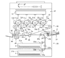
図4(a)は、図1に示す定着ユニット40の概略構成を示す断面図である。図4(b)は、図4(a)に示す定着ヒータの平面図である。
FIG. 4A is a cross-sectional view showing a schematic configuration of the fixing
図4(a)において、定着ユニット40は、定着ヒータ701と、定着フィルム41aと、加圧ローラ41bと、コの字板金711と、サーミスタ712と、ホルダ713と、セルフバイアス回路714を備える。定着ヒータ701は、図4(b)に示すように、セラミックに発熱体が所定のパターンで印刷されたセラミックヒータである。このセラミックヒータは、1秒間で約50℃ほど温度上昇する極めて応答性の高いヒータである。
4A, the fixing
定着フィルム41aは、金属を基材とし、その上に300μmほどのゴム層、さらにフッ素表面処理を施したフィルムで、熱容量が極めて小さく、定着ニップ部のみヒータの熱を伝える。加圧ローラ41bは、硬度60°程度のローラで定着フィルム41aを摩擦駆動している。コの字板金711は、定着フィルム41aを内側から加圧ローラ41b側に加圧するためのコの字状の板金であり、その加圧力は180N程度である。
The fixing
サーミスタ712は、定着温度検出手段として、定着ヒータ701の温度を検出する。本実施形態では、不図示であるが、ヒータ中央部にメインサーミスタが配置されており、定着温度制御のための温度を検出する。また、ヒータ端部にはサブサーミスタ(不図示)が配置されており、小サイズ紙などを通紙した際の非通紙部の温度上昇を検出する。
The
図4(b)において、定着ヒータ701は、発熱体704と電極705を備える。電極705の両端に電圧を印加することで発熱体704が発熱する。図示の発熱体704の印刷パターンは一例であり、定着装置の特性等に応じてさまざまな印刷パターンがある。
In FIG. 4B, the fixing
図5は、定着ヒータ701の駆動/制御を行うヒータ駆動/制御回路の概略構成を示す図(図3に示す定着制御部215と定着ユニット40の詳細回路図)である。
FIG. 5 is a diagram (schematic circuit diagram of the fixing
図5において、ヒータ駆動/制御回路は、画像形成装置全体に電力を供給する交流電源901を備える。また、この交流電源901にACフィルタ902を介して定着ヒータ701が接続されている。ACフィルタ902及び定着ヒータ701間には、トライアック904,抵抗905,906が接続されている。この抵抗905,906間には、フォトトライアックカプラ907が直列接続されている。フォトトライアックカプラ907内の発光ダイオードのVCC側には抵抗908が接続され、該発光ダイオードのアース側には、トランジスタ909のコレクタ端子が接続されている。このトランジスタ909のベース端子には、抵抗910を介してCPU260が接続されている。また、サーミスタ712は、CPU260に接続され、検出した温度情報をCPU260に送信する。
In FIG. 5, the heater drive / control circuit includes an
商用電源等の交流電源901は、ACフィルタ902を介して定着ヒータ701へ電力を供給することにより定着ヒータ701を発熱させる。この定着ヒータ701への供給電力は、トライアック904により通電、遮断が行われる。
An
抵抗905,906は、トライアック904のためのバイアス抵抗である。フォトトライアックカプラ907は、1次、2次間の沿面距離を確保するためのデバイスである。フォトトライアックカプラ907の発光ダイオードに通電することによりトライアック904がオンされる。抵抗908は、フォトトライアックカプラ907の電流を制限するための抵抗であり、トランジスタ909によりオン/オフされる。トランジスタ909は、抵抗910を介してCPU260からのON/OFF信号に従って動作する。
CPU260は、アナログ入力検知部を備え、定着ヒータ701に当接されたサーミスタ712で分圧されて生成される電圧とCPU260内のテーブル情報とを比較することで温度検出を行う。
The
以上のような構成により、プリント時若しくはスタンバイ時等に定着ユニット40を所定の温度に保つように温度制御を行う。
With the configuration described above, temperature control is performed so that the fixing
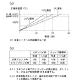
図6(a)は、定着ヒータ701への供給電力を一定に制御した際の定着部(定着装置)の温度と立ち上がり時間との関係の一例を示す特性図である。なお、図6(a)に示す特性図は一例であり、画像形成装置の定着温度、ヒータの抵抗値、供給電力、構成等により決定される。
FIG. 6A is a characteristic diagram showing an example of the relationship between the temperature of the fixing unit (fixing device) and the rise time when the power supplied to the fixing
図6(a)に示すように、定着ヒータ701への供給電力を一定に制御しているので、定着部温度が所定の温度(ここで200℃)に立ち上がるまでの立ち上がり時間は環境温度により異なる。図示例では、環境温度が25℃,15℃,5℃の場合を示す。また、図6(a)に示すように、環境温度が下がれば、立ち上がり時間が延びる。
As shown in FIG. 6A, since the power supplied to the fixing
立上げカーブ判定部304が、図6(a)に示すような特性図に応じたテーブル情報若しくは計算式を備え、定着温度に達するまでに必要な立ち上がり時間を算出する。例えば、環境温度が25℃で定着温度が50℃のときに、カラープリントが要求された場合について説明する。なお、本実施形態では、カラープリント時の定着温度を200℃、白黒時の定着温度を175℃とする。
The rising
上述した条件の場合、定着温度0℃からの立上げ時間15秒から、定着温度0℃から50℃までの立上げ時間約4.4秒を引いた10.6秒が定着温度に達するまでに必要な立ち上がり時間となる。一方、環境温度が5℃であった場合は、同様の計算を行うと、17.5秒(=25‐7.5)となる。 In the case of the above-described conditions, 10.6 seconds after the rise time from the fixing temperature of 0 ° C. to 15 seconds is subtracted from the fixing temperature of 0 ° C. to 50 ° C. for about 4.4 seconds until the fixing temperature is reached. This is the required rise time. On the other hand, when the environmental temperature is 5 ° C., if the same calculation is performed, 17.5 seconds (= 25−7.5) is obtained.
図6(b)は、画像形成条件及び機器状態に応じた定着ニップ部への突入時間の一例を示す図である。 FIG. 6B is a diagram illustrating an example of the entry time to the fixing nip portion according to the image forming conditions and the device state.
図示の表に基づいたテーブル情報等をモジュール制御部201が有する。定着圧部突入タイミング決定部307は、このテーブル情報等を参照し、画像形成条件判定部204と機器状態検出部306からの情報に基づき、画像形成要求時から記録材Pが定着ニップ部に突入するまでの突入時間を算出する。なお、図6(b)に示す表は一例であり、メインコントローラ202の立ち上がり時間、記録材Pの搬送速度、搬送制御、ポリゴンモータなど立ち上がり時間によって決定される。
The
図6(b)に示す表は、モジュール制御部201がメインコントローラ202から画像要求信号を受けてから、定着ニップ部へ記録材Pが突入するまでの突入時間を示したものであり、スタンバイ時とスリープ復帰時との間で10秒程度異なっている。スタンバイ時においては、メインコントローラ202は、画像要求信号を出力した後、すぐに画像データを出力する。そのため、画像形成部10の画像形成時間が定着ニップ部への記録材Pの突入時間を決定することになる。すなわち、ポリゴンモータが停止しているような場合は、その分、定着ニップ部への突入時間は長くなる。
The table shown in FIG. 6B shows the rush time from when the
しかしながら、スリープ復帰時の場合は、メインコントローラ202が立ち上がる時間が必要となるため、画像要求信号はスリープ復帰要求がきたらすぐに出力できるが、画像データを出力するまでに約10秒程度必要である。すなわち、定着ニップ部への記録材Pの突入時間は、メインコントローラ202の立ち上がり時間+画像形成部10の画像形成時間となる。なお、ポリゴンモータは、10秒の間に入るため、加算されない。
However, when returning from sleep, it takes time for the
図6(b)において、カラープリント時と白黒プリント時で突入時間が異なるのは、図1に示した4つの感光ドラムのうち黒色用の感光ドラムが中間転写ベルト31の搬送方向の最上流に配置されるためである。すなわち、カラープリント時には、最上流に配置された感光ドラムで形成された画像が最下流に配置された感光ドラムに到達するまでの時間分長くなる。 In FIG. 6B, the rush time differs between color printing and monochrome printing because the black photosensitive drum of the four photosensitive drums shown in FIG. It is because it is arranged. That is, at the time of color printing, it takes a longer time until an image formed by the photosensitive drum arranged at the most upstream reaches the photosensitive drum arranged at the most downstream.
等速時に比較して1/2速時に突入時間が長くなるのは、記録材Pの搬送速度を1/2速にしているためである。なお、図示の突入時間は、あくまでも一例であり、増速給紙等を行っている場合は等速時と1/2速時の差が縮まる。 The reason why the entry time is longer at 1/2 speed than at constant speed is that the conveyance speed of the recording material P is set to 1/2 speed. The illustrated entry time is merely an example, and the difference between the constant speed and the half speed is reduced when speed-up paper feeding or the like is performed.
次に、本実施形態における定着ユニット40の立上げ制御処理について図7のフローチャートを用いて説明する。
Next, startup control processing of the fixing
図7は、定着ユニット40の立上げ制御処理の一例を示すフローチャートである。なお、図示の処理は、モジュール制御部201内のCPU260が、ROM261等に格納されている制御プログラムを実行することでなされる処理であってもよい。
FIG. 7 is a flowchart illustrating an example of the startup control process of the fixing
画像形成装置は、電源がONされると(ステップS1001)、前多回転などのイニシャル動作(ステップS1002)を行い、スタンバイ状態に移行してユーザからの画像形成要求(プリント要求)を待つ(ステップS1003)。なお、ステップS1001〜S1003は、メインコントローラ202内のCPU250が行うように構成してもよい。
When the power is turned on (step S1001), the image forming apparatus performs an initial operation such as pre-multi rotation (step S1002), shifts to a standby state, and waits for an image formation request (print request) from the user (step S1001). S1003). Note that steps S1001 to S1003 may be performed by the CPU 250 in the
プリント要求があった場合、立上げカーブ判定部304は、図6(a)の特性図を参照し、環境センサ301で検出された環境温度、サーミスタ712で検出された定着ヒータの温度(定着部温度)から定着の立ち上がり時間を算出する(ステップS1004)。
When there is a print request, the start-up
次に、定着圧部突入タイミング決定部307は、図6(b)に示すテーブル情報を参照し、画像形成条件判定部204と機器状態検出部306からの情報に基づき、記録材Pの定着ニップ部への突入時間を算出する(ステップS1005)。
Next, the fixing pressure unit entry
次に、定着駆動タイミング決定部305は、ステップS1004で算出された立ち上がり時間とステップS1005で算出された突入時間を比較し、定着ヒータ701の駆動を開始(ON)するタイミングか否かの判断を行う(ステップS1007)。ONするタイミングで無いと判断された場合(ステップS1007でNO)、ステップS1004に戻り、上述したフローを繰り返す。
Next, the fixing drive
ステップS1007において、定着ヒータ701をONするタイミングであると判断された場合(ステップS1007でYES)、定着駆動タイミング決定部305は、定着ヒータ駆動部303により定着ヒータ701への通電を開始(ON)させる。例えば、定着駆動タイミング決定部305は、立ち上がり時間と突入時間が同じ時間になったときを通電開始タイミングとする。その後、上述した画像形成処理が行われ(ステップS1008)、画像形成終了後にスタンバイ状態に移行し、電源がOFFされるまで(ステップS1009でYES)、ステップS1003以降の処理を繰り返す。なお、定着駆動タイミング決定部305は、サーミスタ712で検出された温度に基づき、決定した通電開始タイミングを補正するように構成されてもよい。
If it is determined in step S1007 that it is time to turn on the fixing heater 701 (YES in step S1007), the fixing drive
上記実施形態によれば、画像形成要求時の画像形成条件と機器状態、環境温度と定着ヒータの温度に応じて、定着ヒータのONするタイミングを制御する。これにより、画像形成要求時から記録材が定着装置に突入するまでに必要な電力を極力少なくすることが可能となり、画像形成装置の省エネ化を一層図ることができる。 According to the above embodiment, the timing for turning on the fixing heater is controlled according to the image forming condition at the time of image formation request, the device state, the environmental temperature, and the temperature of the fixing heater. As a result, it is possible to reduce the power required from the time when an image formation is requested until the recording material enters the fixing device as much as possible, and energy saving of the image forming apparatus can be further achieved.
上記実施形態では、プリント要求時で待つのをスタンバイ状態としているが、スリープ状態に移行された場合でも同様の制御ができるのは言うまでもない。 In the above embodiment, the standby state waits at the time of the print request, but it goes without saying that the same control can be performed even when the sleep state is entered.
また、本発明は、以下の処理を実行することによっても実現される。即ち、上述した実施形態の機能を実現するソフトウェア(プログラム)を、ネットワーク又は各種記憶媒体を介してシステム或いは装置に供給し、そのシステム或いは装置のコンピュータ(またはCPUやMPU等)がプログラムを読み出して実行する処理である。 The present invention can also be realized by executing the following processing. That is, software (program) that realizes the functions of the above-described embodiments is supplied to a system or apparatus via a network or various storage media, and a computer (or CPU, MPU, or the like) of the system or apparatus reads the program. It is a process to be executed.
40 定着ユニット
215 定着制御部
301 環境センサ
303 定着ヒータ駆動部
304 立上げカーブ判定部
305 定着駆動タイミング決定部
306 機器状態検出部
307 定着圧部突入タイミング決定部
701 ヒータ
712 サーミスタ(温度検出部)
40
Claims (5)
前記定着装置の熱源の温度を検出する定着温度検出手段と、
前記定着装置の周辺の環境温度を検出する環境温度検出手段と、
画像形成要求に基づく画像形成条件を判定する判定手段と、
前記判定手段により判定された画像形成条件に基づいて決定される目標定着温度と前記定着温度検出手段で検出された温度情報と前記環境温度検出手段で検出された温度情報に基づき、前記定着装置の熱源の温度が前記目標定着温度に立ち上がるまでの立ち上がり時間を算出する立ち上がり時間算出手段と、
前記判定手段により判定された画像形成条件及び前記画像形成装置が省電力状態であったか否かに基づいて前記画像形成装置に対して前記画像形成要求がなされたときから前記記録材が前記定着装置のニップ部に突入するまでの突入時間を算出する突入時間算出手段と、
前記算出された立ち上がり時間と前記算出された突入時間を比較し、前記定着装置の熱源への通電開始タイミングを決定する駆動タイミング決定手段とを備えることを特徴とする画像形成装置。 In an image forming apparatus including a fixing device that heat-fixes an unfixed developer carried on a recording material by a heat source,
Fixing temperature detecting means for detecting the temperature of the heat source of the fixing device;
Environmental temperature detecting means for detecting the environmental temperature around the fixing device;
Determining means for determining an image forming condition based on the image forming request;
Based on the target fixing temperature determined based on the image forming conditions determined by the determining means, the temperature information detected by the fixing temperature detecting means, and the temperature information detected by the environmental temperature detecting means, the fixing device Rise time calculating means for calculating the rise time until the temperature of the heat source rises to the target fixing temperature;
Wherein said recording material from the time determined by the determination means that the image forming condition and the image forming apparatus the image forming request to the image forming apparatus based on whether there was in the power saving state has been made of the fixing device Rush time calculating means for calculating the rush time until rushing into the nip,
An image forming apparatus, comprising: a drive timing determining unit that compares the calculated rise time and the calculated entry time to determine a start timing of energization of the heat source of the fixing device.
前記定着装置の熱源の温度を検出する定着温度検出工程と、
前記定着装置の周辺の環境温度を検出する環境温度検出工程と、
画像形成要求に基づく画像形成条件を判定する判定工程と、
前記判定工程で判定された画像形成条件に基づいて決定される目標定着温度と前記定着温度検出工程で検出された温度情報と前記環境温度検出工程で検出された温度情報に基づき、前記定着装置の熱源の温度が前記目標定着温度に立ち上がるまでの立ち上がり時間を算出する立ち上がり時間算出工程と、
前記判定工程で判定された画像形成条件及び前記画像形成装置が省電力状態であったか否かに基づいて前記定着装置に対して熱定着要求信号を受けてから前記記録材が前記定着装置のニップ部に突入するまでの突入時間を算出する突入時間算出工程と、
前記算出された立ち上がり時間と前記算出された突入時間を比較し、前記定着装置の熱源への通電開始タイミングを決定する駆動タイミング決定工程とを備えることを特徴とする制御方法。 In a control method of a fixing device for thermally fixing an unfixed developer carried on a recording material by a heat source,
A fixing temperature detecting step for detecting a temperature of a heat source of the fixing device;
An environmental temperature detecting step for detecting an environmental temperature around the fixing device;
A determination step of determining an image formation condition based on the image formation request;
Based on the target fixing temperature determined based on the image forming conditions determined in the determining step, the temperature information detected in the fixing temperature detecting step, and the temperature information detected in the environmental temperature detecting step, the fixing device A rise time calculating step for calculating a rise time until the temperature of the heat source rises to the target fixing temperature;
Based on the image forming condition determined in the determining step and whether or not the image forming apparatus is in a power saving state, the recording material receives a heat fixing request signal from the fixing device and then the nip portion of the fixing device. Rush time calculation step of calculating the rush time until rushing into,
A control method comprising: a drive timing determination step of comparing the calculated rise time and the calculated entry time to determine a start timing of energization to the heat source of the fixing device.
Priority Applications (1)
| Application Number | Priority Date | Filing Date | Title |
|---|---|---|---|
| JP2010086932A JP5595090B2 (en) | 2010-04-05 | 2010-04-05 | Image forming apparatus and fixing device control method |
Applications Claiming Priority (1)
| Application Number | Priority Date | Filing Date | Title |
|---|---|---|---|
| JP2010086932A JP5595090B2 (en) | 2010-04-05 | 2010-04-05 | Image forming apparatus and fixing device control method |
Publications (2)
| Publication Number | Publication Date |
|---|---|
| JP2011221082A JP2011221082A (en) | 2011-11-04 |
| JP5595090B2 true JP5595090B2 (en) | 2014-09-24 |
Family
ID=45038178
Family Applications (1)
| Application Number | Title | Priority Date | Filing Date |
|---|---|---|---|
| JP2010086932A Expired - Fee Related JP5595090B2 (en) | 2010-04-05 | 2010-04-05 | Image forming apparatus and fixing device control method |
Country Status (1)
| Country | Link |
|---|---|
| JP (1) | JP5595090B2 (en) |
Families Citing this family (1)
| Publication number | Priority date | Publication date | Assignee | Title |
|---|---|---|---|---|
| JP2014098737A (en) | 2012-11-13 | 2014-05-29 | Ricoh Co Ltd | Image forming apparatus |
Family Cites Families (8)
| Publication number | Priority date | Publication date | Assignee | Title |
|---|---|---|---|---|
| JPH05333655A (en) * | 1992-05-28 | 1993-12-17 | Ricoh Co Ltd | Fixing device temperature controller |
| JPH06194993A (en) * | 1992-12-25 | 1994-07-15 | Canon Inc | Image forming apparatus and fixing apparatus |
| JP3847892B2 (en) * | 1997-04-14 | 2006-11-22 | キヤノン株式会社 | Image forming apparatus and energization control method thereof |
| JP2002072761A (en) * | 2000-08-31 | 2002-03-12 | Ricoh Co Ltd | Image forming apparatus and image forming system |
| JP2002189378A (en) * | 2000-12-20 | 2002-07-05 | Canon Inc | Image forming device |
| JP2004177853A (en) * | 2002-11-29 | 2004-06-24 | Canon Inc | Image forming device |
| JP2004198534A (en) * | 2002-12-16 | 2004-07-15 | Seiko Epson Corp | Fixing device temperature control method and image forming apparatus |
| JP5353019B2 (en) * | 2008-02-04 | 2013-11-27 | 株式会社リコー | Image forming apparatus |
-
2010
- 2010-04-05 JP JP2010086932A patent/JP5595090B2/en not_active Expired - Fee Related
Also Published As
| Publication number | Publication date |
|---|---|
| JP2011221082A (en) | 2011-11-04 |
Similar Documents
| Publication | Publication Date | Title |
|---|---|---|
| US8311431B2 (en) | Image forming apparatus comprising a control section configured to carry out a control process including setting a power saving mode | |
| JP2004126191A (en) | Image forming device | |
| JP6060940B2 (en) | Image forming apparatus | |
| CN102455647A (en) | Image forming apparatus and initialization method of image forming apparatus | |
| JP4542835B2 (en) | Image forming apparatus and image forming method | |
| JP5320321B2 (en) | Image forming apparatus | |
| JP4922842B2 (en) | Fixing apparatus, image forming apparatus, temperature control method, program, and storage medium | |
| JP2009042655A (en) | Temperature control device for heated body, fixing device, fixing method, image forming apparatus, and image forming method | |
| JP6080000B2 (en) | Image forming apparatus | |
| JP2016184015A (en) | Image forming apparatus | |
| JP5595090B2 (en) | Image forming apparatus and fixing device control method | |
| US20160252852A1 (en) | Image forming apparatus | |
| JP5611295B2 (en) | Image forming apparatus | |
| JP6074960B2 (en) | Heating control apparatus, image forming apparatus, and heating control method | |
| JP2014164183A (en) | Fixing device, image forming apparatus, fixing control method, and fixing control program | |
| JP5552850B2 (en) | Fixing control method, fixing device, and image forming apparatus | |
| JP5516310B2 (en) | Heating control method for fixing process, fixing device for implementing the heating control method, and image forming apparatus | |
| US8238775B2 (en) | Image heating apparatus | |
| JP2010122448A (en) | Image forming apparatus | |
| US11644771B2 (en) | Image forming apparatus | |
| RU2477507C2 (en) | Image heating apparatus | |
| JP5900038B2 (en) | Image forming apparatus and image forming method | |
| JP4615320B2 (en) | Image forming apparatus and control method | |
| JP2013125256A (en) | Image forming apparatus | |
| JP2004126173A (en) | Image forming device |
Legal Events
| Date | Code | Title | Description |
|---|---|---|---|
| A621 | Written request for application examination |
Free format text: JAPANESE INTERMEDIATE CODE: A621 Effective date: 20130328 |
|
| A977 | Report on retrieval |
Free format text: JAPANESE INTERMEDIATE CODE: A971007 Effective date: 20131121 |
|
| A131 | Notification of reasons for refusal |
Free format text: JAPANESE INTERMEDIATE CODE: A131 Effective date: 20131126 |
|
| A521 | Written amendment |
Free format text: JAPANESE INTERMEDIATE CODE: A523 Effective date: 20140127 |
|
| TRDD | Decision of grant or rejection written | ||
| A01 | Written decision to grant a patent or to grant a registration (utility model) |
Free format text: JAPANESE INTERMEDIATE CODE: A01 Effective date: 20140708 |
|
| A61 | First payment of annual fees (during grant procedure) |
Free format text: JAPANESE INTERMEDIATE CODE: A61 Effective date: 20140805 |
|
| LAPS | Cancellation because of no payment of annual fees |