JP2010122448A - Image forming apparatus - Google Patents

Image forming apparatus Download PDF

Info

Publication number
JP2010122448A
JP2010122448A JP2008295797A JP2008295797A JP2010122448A JP 2010122448 A JP2010122448 A JP 2010122448A JP 2008295797 A JP2008295797 A JP 2008295797A JP 2008295797 A JP2008295797 A JP 2008295797A JP 2010122448 A JP2010122448 A JP 2010122448A
Authority
JP
Japan
Prior art keywords
temperature
image forming
unit
forming apparatus
saving mode
Prior art date
Legal status (The legal status is an assumption and is not a legal conclusion. Google has not performed a legal analysis and makes no representation as to the accuracy of the status listed.)
Pending
Application number
JP2008295797A
Other languages
Japanese (ja)
Other versions
JP2010122448A5 (en
Inventor
Hajime Kaji
一 鍜治
Current Assignee (The listed assignees may be inaccurate. Google has not performed a legal analysis and makes no representation or warranty as to the accuracy of the list.)
Canon Inc
Original Assignee
Canon Inc
Priority date (The priority date is an assumption and is not a legal conclusion. Google has not performed a legal analysis and makes no representation as to the accuracy of the date listed.)
Filing date
Publication date
Application filed by Canon Inc filed Critical Canon Inc
Priority to JP2008295797A priority Critical patent/JP2010122448A/en
Publication of JP2010122448A publication Critical patent/JP2010122448A/en
Publication of JP2010122448A5 publication Critical patent/JP2010122448A5/ja
Pending legal-status Critical Current

Links

Images

Abstract

<P>PROBLEM TO BE SOLVED: To achieve the convenience and energy saving of an image forming apparatus by determining the timing of shifting into a power saving mode in consideration of the time required for recovery from the power saving mode. <P>SOLUTION: The image forming apparatus is shifted into the power saving mode, when the temperature of a fixing part 40 after the formation of an image is completed is decreased below a predetermined temperature. The predetermined temperature is such a temperature that the predicted time required to reach a fixing target temperature from the detected temperature of the fixing part 40 is not shorter than the rising time of a controller 202 in recovery from the power saving mode. <P>COPYRIGHT: (C)2010,JPO&INPIT

Description

本発明は、シートに加熱定着する画像形成装置に関し、特に省電力モードへの移行の制御に関するものである。   The present invention relates to an image forming apparatus that heats and fixes a sheet, and particularly to control of shifting to a power saving mode.

近年、環境問題等の点からプリンタ、複写機、ファクシミリ等の電子写真装置の省エネルギー化が提案されている。   In recent years, energy saving of electrophotographic apparatuses such as printers, copiers, facsimiles and the like has been proposed in view of environmental problems.

例えば、特許文献1では、画像形成装置における消費電力算出機能をもつことにより、ユーザが消費電力値を把握する事ができるように構成されている。そして、ユーザが消費電力の情報に基づき電力供給のスケジューリングを行い、動作環境に応じた省電力モードを設定することができる。例えば、ユーザが画像形成装置の一週間の動作状況等を把握して、省エネルギーモードに移行する時刻を設定することができる。
特開2002−225395号公報
For example, Patent Document 1 is configured so that the user can grasp the power consumption value by having a power consumption calculation function in the image forming apparatus. Then, the user can schedule power supply based on the power consumption information, and can set the power saving mode according to the operating environment. For example, the user can grasp the operation status of the image forming apparatus for one week and set the time to shift to the energy saving mode.
JP 2002-225395 A

しかしながら、従来の画像形成装置においては、省エネルギーモードへの移行条件をユーザが設定するような構成となっている。すなわち、各使用ユーザに条件設定を判断させている為、ユーザが利便性、省エネルギー効果を把握した上で設定する必要があり、効果的な設定を行うには試行錯誤が必要で操作性が悪い。   However, the conventional image forming apparatus is configured such that the user sets the conditions for shifting to the energy saving mode. In other words, since each user uses to determine the condition setting, it is necessary for the user to make settings after understanding the convenience and energy saving effect. Trial and error are necessary for effective setting, and operability is poor. .

また、スケジューリングをしたとしても、例えば、大量プリント後すぐに省電力モードに移行してしまったり、少量プリント後になかなか低電力モードへ移行しない等、期待した省エネルギー効果がえられない場合がある。さらには大量プリント後に定着器が記録紙に熱を奪われた状態ですぐに省電力モードに移行してしまうと、省電力モードからの復帰後のファーストプリント時間が長くなってしまう等利便性が悪くなる可能性がある。   Even if scheduling is performed, the expected energy saving effect may not be obtained, for example, the mode is shifted to the power saving mode immediately after mass printing, or the mode is not easily shifted to the low power mode after printing a small amount. In addition, if the fixing device is deprived of heat on the recording paper after a large number of prints, and immediately shifts to the power saving mode, the first print time after returning from the power saving mode becomes longer. It can get worse.

そこで本発明は上記した事情に鑑み、省電力モードを搭載した画像形成装置において、使用状況に応じて、利便性、省エネ性を両立した動作を自動で制御する画像形成装置を提供することを目的としている。   SUMMARY OF THE INVENTION In view of the above circumstances, an object of the present invention is to provide an image forming apparatus that automatically controls operations that achieve both convenience and energy saving in accordance with usage conditions in an image forming apparatus equipped with a power saving mode. It is said.

上記の課題を解決するために、本発明の画像形成装置は、画像形成が実行されていない状態の消費電力を低減させる省電力モードを有する画像形成装置において、シートに画像を形成する像形成手段と、画像が形成されたシートを定着する定着部と、前記定着部の温度を検出する温度検出手段と、前記定着部の温度を目標温度となる様に制御する温度制御手段と、画像形成終了後の前記温度検出手段により検出された温度が所定温度よりも低くなると前記画像形成装置を前記省電力モードへ移行させる制御部と、有することを特徴とする。   In order to solve the above problems, an image forming apparatus according to the present invention includes an image forming unit that forms an image on a sheet in an image forming apparatus having a power saving mode for reducing power consumption in a state where image formation is not performed. A fixing unit that fixes the sheet on which the image is formed, a temperature detection unit that detects the temperature of the fixing unit, a temperature control unit that controls the temperature of the fixing unit to be a target temperature, and completion of image formation And a control unit that shifts the image forming apparatus to the power saving mode when a temperature detected by the temperature detecting unit later becomes lower than a predetermined temperature.

本発明によれば、省電力モードからの予想復帰時間に応じて省電力モードに移行する時間を可変することにより、画像形成装置の利便性を落す事なく最適なタイミングで省電力モードに移行することが可能となる。   According to the present invention, by changing the time for shifting to the power saving mode according to the expected return time from the power saving mode, the mode is shifted to the power saving mode at an optimal timing without deteriorating the convenience of the image forming apparatus. It becomes possible.

(第1の実施の形態)
以下、本発明を実施するための最良の形態について、図面を参照して説明する。
(First embodiment)
The best mode for carrying out the present invention will be described below with reference to the drawings.

図1は、本発明の一実施の形態に係る画像形成装置の構成を示す断面図である。   FIG. 1 is a cross-sectional view showing a configuration of an image forming apparatus according to an embodiment of the present invention.

この画像形成装置は、複数の画像形成部を並列に配した電子写真方式のカラー画像形成装置である。   This image forming apparatus is an electrophotographic color image forming apparatus in which a plurality of image forming units are arranged in parallel.

この画像形成装置は、画像形成部10、給紙ユニット20、中間転写ユニット30、定着ユニット40から構成される。   The image forming apparatus includes an image forming unit 10, a paper feeding unit 20, an intermediate transfer unit 30, and a fixing unit 40.

画像形成部10は次に述べるような構成になっている。像担持体としての感光ドラム11a、11b、11c、11dはその中心で軸支され、矢印方向に回転駆動される。感光ドラム11a〜11dの外周面に対向してその回転方向に順番に、一次帯電器12a、12b、12c、12d、レーザスキャナユニット13、現像装置14a、14b、14c、14dが配置されている。一次帯電器12a〜12dは各々、感光ドラム11a〜11dの各表面に均一な帯電量の電荷を与える。次いでレーザスキャナユニット13が、記録画像信号に応じて変調されたレーザビームなどの各光線を感光ドラム11a〜11d上にそれぞれ照射し、これによって、感光ドラム11a〜11d上に静電潜像をそれぞれ形成する。   The image forming unit 10 is configured as described below. Photosensitive drums 11a, 11b, 11c, and 11d as image carriers are pivotally supported at their centers and are driven to rotate in the direction of the arrow. The primary chargers 12a, 12b, 12c, 12d, the laser scanner unit 13, and the developing devices 14a, 14b, 14c, 14d are arranged in order in the rotation direction so as to face the outer peripheral surfaces of the photosensitive drums 11a to 11d. The primary chargers 12a to 12d respectively apply a uniform charge amount to the surfaces of the photosensitive drums 11a to 11d. Next, the laser scanner unit 13 irradiates the photosensitive drums 11a to 11d with light beams such as a laser beam modulated according to the recording image signal, and thereby electrostatic latent images are respectively formed on the photosensitive drums 11a to 11d. Form.

さらに、イエロー、シアン、マゼンタ、ブラックといった4色の現像剤(以下、これを「トナー」と呼ぶ)をそれぞれ収納した現像装置14a〜14dが、上記静電潜像を顕像化する。顕像化された可視画像は画像転写領域Ta、Tb、Tc、Tdにて中間転写ベルト31に転写される。クリーニング装置15a、15b、15c、15dは中間転写ベルト31に転写されずに感光ドラム11a〜11d上に残されたトナーを掻き落としてドラム表面の清掃を行う。以上に示したプロセスにより、中間転写ベルト31上に4色の各トナー画像が重ねて転写される。   Further, the developing devices 14a to 14d respectively containing developer of four colors such as yellow, cyan, magenta and black (hereinafter referred to as “toner”) visualize the electrostatic latent image. The visualized visible image is transferred to the intermediate transfer belt 31 in the image transfer areas Ta, Tb, Tc, and Td. The cleaning devices 15a, 15b, 15c, and 15d clean the drum surface by scraping off toner remaining on the photosensitive drums 11a to 11d without being transferred to the intermediate transfer belt 31. Through the process described above, the four color toner images are transferred onto the intermediate transfer belt 31 in an overlapping manner.

給紙ユニット20は、シートPを収納するためのカセット21a、21bおよび手差しトレイ27を有する。カセット21a、21bまたは手差しトレイ27に収納されたシートPは1枚ずつピックアップローラ22a、22b、26により送り出され、給紙ローラ対23a,23b、23cによりレジストレーションローラ25まで搬送される。そして画像形成部10の画像形成タイミングに合わせてレジストレーションローラ25が駆動され、シートPを二次転写領域Teへ送り出す。   The sheet feeding unit 20 includes cassettes 21 a and 21 b for storing sheets P and a manual feed tray 27. The sheets P stored in the cassettes 21a, 21b or the manual feed tray 27 are sent out one by one by the pickup rollers 22a, 22b, 26, and conveyed to the registration roller 25 by the pair of paper feed rollers 23a, 23b, 23c. Then, the registration roller 25 is driven in accordance with the image formation timing of the image forming unit 10 to send out the sheet P to the secondary transfer region Te.

各感光ドラム11a〜11dと中間転写ベルト31とが対向する一次転写領域Ta〜Tdでは、中間転写ベルト31の裏側に一次転写用帯電器35a〜35dが配置される。従動ローラ34に対向して二次転写ローラ36が配置され、中間転写ベルト31とのニップによって二次転写領域Teを形成する。二次転写ローラ36は中間転写ベルト31に対して適度な圧力で加圧されている。   In the primary transfer areas Ta to Td where the photosensitive drums 11 a to 11 d and the intermediate transfer belt 31 face each other, primary transfer chargers 35 a to 35 d are disposed on the back side of the intermediate transfer belt 31. A secondary transfer roller 36 is disposed so as to face the driven roller 34, and a secondary transfer region Te is formed by a nip with the intermediate transfer belt 31. The secondary transfer roller 36 is pressed against the intermediate transfer belt 31 with an appropriate pressure.

定着ユニット40は、内部にセラミックヒータ基板などの熱源を備えた定着フィルムとセラミックヒータ基板に前記フィルムをはさんで加圧される加圧ローラ(このローラに熱源を備える場合もある)から成る。また、定着ユニット40の上流には定着ユニットの40のローラのニップ部へ記録材Pを導く為のガイド43が設けられる。また、前記定着ユニット40を通過した記録材Pを装置の外部に導き出すための外排紙ローラ45が配設される。   The fixing unit 40 includes a fixing film having a heat source such as a ceramic heater substrate therein, and a pressure roller (which may be provided with a heat source in some cases) that presses the film across the ceramic heater substrate. Further, a guide 43 for guiding the recording material P to the nip portion of the 40 rollers of the fixing unit is provided upstream of the fixing unit 40. In addition, an outer paper discharge roller 45 is provided for guiding the recording material P that has passed through the fixing unit 40 to the outside of the apparatus.

次に、画像形成装置の動作を説明する。   Next, the operation of the image forming apparatus will be described.

画像形成動作開始の指示が不図示の操作部或いは外部機器から入力されると、選択されたシートサイズに対応した給紙段からシートPが給紙される。例えばカセット21aから給紙された場合について説明すると、まずピックアップローラ22aにより、カセット21aからシートPが1枚ずつ送り出される。そして給紙ローラ対23cによってシートPが給紙ガイド24の間を案内されてレジストレーションローラ25まで搬送される。その時レジストレーションローラ25は停止されており、シートPの先端はレジストレーションローラ25のニップ部に突き当たる。その後、画像形成部10により中間転写ベルト31に転写されたトナー画像が二次転写領域Teへ到達するタイミングに合わせてレジストレーションローラ25は回転を始める。   When an instruction to start an image forming operation is input from an operation unit (not shown) or an external device, the sheet P is fed from a paper feed stage corresponding to the selected sheet size. For example, a case where paper is fed from the cassette 21a will be described. First, the sheet P is sent out one by one from the cassette 21a by the pickup roller 22a. The sheet P is guided between the sheet feeding guides 24 by the pair of sheet feeding rollers 23c and conveyed to the registration rollers 25. At that time, the registration roller 25 is stopped, and the leading edge of the sheet P hits the nip portion of the registration roller 25. Thereafter, the registration roller 25 starts rotating in accordance with the timing at which the toner image transferred to the intermediate transfer belt 31 by the image forming unit 10 reaches the secondary transfer region Te.

一方、画像形成部10では、画像形成動作開始信号が発せられると、中間転写ベルト31の回転方向において一番上流にある感光ドラム11d上に形成されたトナー画像が一次転写領域Tdにおいて中間転写ベルト31に転写される。転写されたトナー像は次の一次転写領域Tcまで搬送される。一次転写領域Tcでは、一次転写領域Tdから一次転写領域Tcまでのトナー像を搬送するためにかかる時間だけ遅延して画像形成が行われており、前画像の上に位置を合わせて次のトナー像が転写される。一次転写領域Tb、一次転写領域Taも同様の工程が繰り返され、結局4色のトナー像が中間転写ベルト31上において転写される。   On the other hand, when an image forming operation start signal is issued in the image forming unit 10, the toner image formed on the photosensitive drum 11 d that is the most upstream in the rotation direction of the intermediate transfer belt 31 is transferred to the intermediate transfer belt in the primary transfer region Td. 31 is transferred. The transferred toner image is conveyed to the next primary transfer region Tc. In the primary transfer area Tc, image formation is delayed by the time taken to convey the toner image from the primary transfer area Td to the primary transfer area Tc, and the next toner is aligned with the previous image. The image is transferred. The same process is repeated for the primary transfer area Tb and the primary transfer area Ta, and the four color toner images are finally transferred onto the intermediate transfer belt 31.

その後、シートPが二次転写領域Teに進入、中間転写ベルト31に接触すると、シートPの通過タイミングに合わせて二次転写ローラ36に高電圧が印加される。そして、前述したプロセスにより中間転写ベルト31上に形成された4色のトナー画像がシートPの表面に転写される。その後、シートPは搬送ガイド43によって定着部40のニップ部まで正確に案内される。そして定着部40で熱及びニップの圧力によってトナー画像がシートPの表面に定着される。その後、シートPは内排紙ローラ44及び外排紙ローラ45により搬送され、機外に排出される。   Thereafter, when the sheet P enters the secondary transfer region Te and contacts the intermediate transfer belt 31, a high voltage is applied to the secondary transfer roller 36 in accordance with the passing timing of the sheet P. Then, the four-color toner images formed on the intermediate transfer belt 31 by the above-described process are transferred onto the surface of the sheet P. Thereafter, the sheet P is accurately guided to the nip portion of the fixing unit 40 by the conveyance guide 43. The toner image is fixed on the surface of the sheet P by the heat and nip pressure in the fixing unit 40. Thereafter, the sheet P is conveyed by the inner discharge roller 44 and the outer discharge roller 45 and discharged outside the apparatus.

図2は画像形成装置の制御部ブロック図である。   FIG. 2 is a block diagram of the control unit of the image forming apparatus.

201は画像処理装置全体の各モジュールの制御を行うモジュール制御部である。モジュール制御部201は、CPU(不図示)、制御プログラムやデータを記憶したROM(不図示)、作業用記憶領域等として用いるRAM、各負荷のドライバ(不図示)等からなるもので、メインコントローラ202からの指示により、プログラムを実行する。駆動負荷類208は、給紙系、搬送系、光学系の駆動を行うモータ、クラッチ、ソレノイドなどで構成される。センサ類210は、搬送される用紙を検知するための紙検知センサ、現像器内のトナー量を検知するトナー残検センサ、各負荷のホームポジション、ドアの開閉状態等を検知するためのスイッチ等で構成される。高圧ユニット213はモジュール制御部201の指示に従って、1次帯電器113、現像器118、転写前帯電器121、転写帯電器133、分離帯電器134へ高圧出力を行う。定着部40は、オンデマンドヒータ、温度検知部、ヒータ駆動部等で構成され(定着器構成に関しては後述する)、モジュール制御部201からのオンオフ信号によって定着器の温度を目標温度に制御する温調制御が行われる。   Reference numeral 201 denotes a module control unit that controls each module of the entire image processing apparatus. The module control unit 201 includes a CPU (not shown), a ROM (not shown) storing control programs and data, a RAM used as a work storage area, etc., a driver (not shown) for each load, and the like. The program is executed according to an instruction from 202. The driving loads 208 are configured by a motor, a clutch, a solenoid, and the like that drive a paper feeding system, a transport system, and an optical system. Sensors 210 include a paper detection sensor for detecting the conveyed paper, a toner residual detection sensor for detecting the amount of toner in the developing unit, a home position for each load, a switch for detecting the open / closed state of the door, and the like. Consists of. The high voltage unit 213 outputs a high voltage to the primary charger 113, the developing device 118, the pre-transfer charger 121, the transfer charger 133, and the separation charger 134 in accordance with an instruction from the module control unit 201. The fixing unit 40 includes an on-demand heater, a temperature detection unit, a heater driving unit, and the like (the fixing unit configuration will be described later), and is a temperature that controls the temperature of the fixing unit to a target temperature by an on / off signal from the module control unit 201. Key control is performed.

220は操作部であり、操作者が操作するキーや、装置の状態等を表示する液晶、LEDから構成される。   An operation unit 220 includes a key operated by the operator, a liquid crystal display that displays the state of the apparatus, and an LED.

メインコントローラ202は、CPU250、ROM251、通信部204を有し、操作部220、外部機器106、モジュール制御部201、電力制御部203と通信を行う。なお、通信部204は、CPU250に電力供給されていない状態でも、操作部220からの省電力モードからの復帰の指示や外部からの像形成のジョブの入力を監視することができる。即ち、通信部は監視部として機能する。また、通信部204の消費電力はCPU250に比べて低くなっている。また、メインコントローラ202は、画像形成装置の画像読取部や外部機器からの画像信号に対して種々の画像処理を行う。さらに、電力制御部203はメインコントローラ202からの指示により、モジュール制御部201及びメインコントローラ202への電力供給の制御を行う。   The main controller 202 includes a CPU 250, a ROM 251, and a communication unit 204, and communicates with the operation unit 220, the external device 106, the module control unit 201, and the power control unit 203. Note that the communication unit 204 can monitor an instruction to return from the power saving mode from the operation unit 220 and an input of an image forming job from the outside even when the power is not supplied to the CPU 250. That is, the communication unit functions as a monitoring unit. Further, the power consumption of the communication unit 204 is lower than that of the CPU 250. The main controller 202 performs various image processing on image signals from an image reading unit of the image forming apparatus and an external device. Further, the power control unit 203 controls power supply to the module control unit 201 and the main controller 202 in accordance with an instruction from the main controller 202.

本実施形態の画像形成装置は、画像形成動作を実行していないときの動作モードとして省電力モードとスタンバイモードを有する。スタンバイモードから省電力モードへの移行、省電力モードからスタンバイモードへの復帰は通信部204から電力制御部203へ指示することで行われる。本実施形態におけるスタンバイモードとは、画像形成装置の各モジュールに電源が供給されている状態で、操作部、ネットワーク、FAXより画像形成要求がされたら即座に印刷開始可能な状態を指す(但し、定着部の温調制御は行っていない)。また省電力モードとは、画像形成が実行されていない状態の消費電力を低減させるため、操作部220と通信部204に電力供給され、CPU250やROM251には電力供給されていない状態であり、スタンバイモード時よりも消費電力が少ない状態を指す。スタンバイモードから省電力モードへの移行制御フローに関しては後述する。   The image forming apparatus of the present embodiment has a power saving mode and a standby mode as operation modes when the image forming operation is not executed. The transition from the standby mode to the power saving mode and the return from the power saving mode to the standby mode are performed by instructing the power control unit 203 from the communication unit 204. The standby mode in the present embodiment refers to a state in which power can be supplied to each module of the image forming apparatus and printing can be started immediately when an image forming request is made from the operation unit, the network, or a FAX (however, The temperature control of the fixing unit is not performed. The power saving mode is a state in which power is supplied to the operation unit 220 and the communication unit 204 and power is not supplied to the CPU 250 and the ROM 251 in order to reduce power consumption in a state where image formation is not executed. It refers to a state that consumes less power than in the mode. The transition control flow from the standby mode to the power saving mode will be described later.

また、メインコントローラ202は、省電力モードからスタンバイモードへ復帰する際に、メインコントローラ202の中の各部が正常に動作するように立ち上がり動作(初期化動作)を行う。立ち上がり動作が終了して初めてメインコントローラ202は画像形成装置を制御可能な状態に立ち上がる。このメインコントローラの立ち上がりに要する時間は本実施形態では10秒とする。   Further, when the main controller 202 returns from the power saving mode to the standby mode, the main controller 202 performs a rising operation (initialization operation) so that each unit in the main controller 202 operates normally. Only after the start-up operation is completed, the main controller 202 starts up in a state where the image forming apparatus can be controlled. In this embodiment, the time required for the main controller to rise is 10 seconds.

次に図3〜5を用いて定着部40とその駆動回路について説明する。   Next, the fixing unit 40 and its drive circuit will be described with reference to FIGS.

図3は図1の定着部40の構成図である。701はセラミックヒータ、702は定着フィルム、703は加圧ローラ、711は板金、712は温度検出用サーミスタ、713はホルダ、714はセルフバイアス回路である。セラミックヒータ701はセラミックに発熱パターンを印刷したヒータ(図4参照)で1秒間で約50℃ほど温度上昇する極めて応答性の高いヒータである。定着フィルム702は金属を基材とし、その上に300μmほどのゴム層、さらにフッ素表面処理を施したフィルムで、熱容量が極めて小さく、ニップ部のみヒータの熱を伝える。加圧ローラ703は硬度60°程度のローラで定着フィルム702を摩擦駆動している。板金711はコの字型をしており、定着フィルム702を内側から加圧ローラ703に加圧しており、その加圧力は180N程度である。サーミスタ712はメインサーミスタとサブサーミスタを有し、それぞれヒータ701の温度を検出する。メインサーミスタは紙面手前奥方向(加圧ローラ703の軸方向)におけるヒータ701の中央に配置され、定着温度制御のための温度を検出している。サブサーミスタは加圧ローラ703の軸方向におけるヒータ701の端部に配置され、A4R,B5サイズ等の小サイズ紙などを通紙した際の非通紙部の温度上昇を検知している。   FIG. 3 is a configuration diagram of the fixing unit 40 of FIG. Reference numeral 701 denotes a ceramic heater, 702 a fixing film, 703 a pressure roller, 711 a sheet metal, 712 a temperature detection thermistor, 713 a holder, and 714 a self-bias circuit. The ceramic heater 701 is a heater (see FIG. 4) in which a heat generation pattern is printed on ceramic, and is a highly responsive heater that rises by about 50 ° C. in one second. The fixing film 702 is made of a metal as a base material, a film having a rubber layer of about 300 μm, and a fluorine surface treatment. The fixing film 702 has a very small heat capacity and transmits the heat of the heater only to the nip portion. The pressure roller 703 is a roller having a hardness of about 60 ° and frictionally drives the fixing film 702. The sheet metal 711 has a U-shape and presses the fixing film 702 against the pressure roller 703 from the inside, and the pressure is about 180N. The thermistor 712 has a main thermistor and a sub-thermistor, and detects the temperature of the heater 701, respectively. The main thermistor is disposed at the center of the heater 701 in the front and back direction (the axial direction of the pressure roller 703), and detects the temperature for fixing temperature control. The sub-thermistor is disposed at the end of the heater 701 in the axial direction of the pressure roller 703, and detects a temperature rise in a non-sheet passing portion when a small size paper such as A4R or B5 size is passed.

図4は図3のヒータ701の平面図である。図中704が発熱体で705は電極である。電極705の両端に電圧を印加することで発熱体704が発熱する。本ヒータの発熱体のパターンは一例であり、定着部40の特性等に応じて決定すればよい。   FIG. 4 is a plan view of the heater 701 in FIG. In the figure, 704 is a heating element and 705 is an electrode. The heating element 704 generates heat by applying a voltage to both ends of the electrode 705. The heating element pattern of the heater is an example, and may be determined according to the characteristics of the fixing unit 40.

図5は、ヒータ701の駆動制御を行うヒータ駆動制御回路の構成を示す回路図(図2の制御ブロック図で示すところのモジュール制御部201と定着部40の詳細回路図)である。901は画像形成装置全体に電力を供給する商用電源等の交流電源であり、この交流電源901にACフィルタ902を介してヒータ701に電力が供給される。ACフィルタ902及びセラミックヒータ701間には、トライアック904,抵抗905,906及びこの抵抗905,906間に直列接続されたフォトトライアックカプラ907が接続されている。抵抗905,906は、トライアック904のためのバイアス抵抗である。また、フォトトライアックカプラ907は、電気的な1次・2次回路間の沿面距離を確保するためのデバイスである。このフォトトライアックカプラ907の発光部側の一端は抵抗908を介して電源Vccに接続される。抵抗908は、フォトトライアックカプラ907の電流を制限するための抵抗である。フォトトライアックカプラ907の発光部側の他端はトランジスタ909のコレクタ端子に接続されている。このトランジスタ909のベース端子には抵抗910を介してCPU920(図2の制御ブロック図では、モジュール制御部201内に配置される)が接続されている。   FIG. 5 is a circuit diagram (detailed circuit diagram of the module control unit 201 and the fixing unit 40 shown in the control block diagram of FIG. 2) showing the configuration of the heater drive control circuit that controls the drive of the heater 701. Reference numeral 901 denotes an AC power source such as a commercial power source that supplies power to the entire image forming apparatus. Power is supplied to the AC power source 901 via the AC filter 902. A triac 904, resistors 905 and 906, and a phototriac coupler 907 connected in series between the resistors 905 and 906 are connected between the AC filter 902 and the ceramic heater 701. Resistors 905 and 906 are bias resistors for the triac 904. The phototriac coupler 907 is a device for ensuring a creepage distance between the electrical primary and secondary circuits. One end of the phototriac coupler 907 on the light emitting unit side is connected to the power supply Vcc via a resistor 908. The resistor 908 is a resistor for limiting the current of the phototriac coupler 907. The other end of the phototriac coupler 907 on the light emitting unit side is connected to the collector terminal of the transistor 909. A CPU 920 (arranged in the module control unit 201 in the control block diagram of FIG. 2) is connected to the base terminal of the transistor 909 via a resistor 910.

交流電源901は、ACフィルタ902を介してセラミックヒータ701へ電力を供給することによりセラミックヒータ701を発熱させる。トライアック904は、セラミックヒータ701への供給電力の通電、遮断を制御する。れる。トランジスタ909はフォトトライアックカプラ907の発光ダイオードの通電をオンオフ制御し、発光ダイオードが発光するとトライアック904がオンされる。トランジスタ909は、抵抗910を介してCPU920からのヒータON信号にしたがって動作する。CPU920はアナログ入力検知部をもち、セラミックヒータ701に当接されたサーミスタ712で分圧されて生成される電圧とCPU920内のテーブルを比較する事でヒータ701の温度検知を行う。   The AC power source 901 causes the ceramic heater 701 to generate heat by supplying power to the ceramic heater 701 via the AC filter 902. The triac 904 controls energization and interruption of the power supplied to the ceramic heater 701. It is. The transistor 909 controls ON / OFF of the light-emitting diode of the phototriac coupler 907, and the triac 904 is turned on when the light-emitting diode emits light. The transistor 909 operates according to the heater ON signal from the CPU 920 via the resistor 910. The CPU 920 has an analog input detection unit, and detects the temperature of the heater 701 by comparing the voltage generated by dividing the voltage with the thermistor 712 in contact with the ceramic heater 701 and the table in the CPU 920.

以上のような構成によりプリント時もしくは、スタンバイ時等に定着部40を所定の温度に保つように温度制御を行う。   With the configuration described above, temperature control is performed so that the fixing unit 40 is maintained at a predetermined temperature during printing or standby.

図6は、プリント後(定着部の温度制御終了後)における定着部40の温度推移を示す図である。画像形成終了後、スタンバイモードになると、定着部40の温度制御が終了する。画像形成を行っていた時間等に応じて定着部40に蓄積された熱量が異なる為、温度制御終了後の定着部40の温度変化は画像形成を行っていた時間等の条件によって異なる。図6には画像形成を500枚行った後、50枚行ったあとの温度推移を表している。500枚プリント後は定着部40(特に加圧ローラ703)に熱が蓄積されている為、画像形成終了後の温度低下率が比較的低く。100℃に低下するまでに約300秒の時間を要している。一方、50枚プリントを行った後は、温度低下率が比較的高く、100℃に低下するまでに60秒程度しか掛かっていないことがわかる。これは前述したように、定着部40の熱の蓄積によるものなので、定着部40の温度と像形成に要した時間等で変化するが、規定の枚数(500枚程度)以上では、ほぼ同じような温度カーブを示す。   FIG. 6 is a diagram showing a temperature transition of the fixing unit 40 after printing (after the temperature control of the fixing unit is finished). When the standby mode is set after the image formation is finished, the temperature control of the fixing unit 40 is finished. Since the amount of heat accumulated in the fixing unit 40 varies depending on the time during which image formation has been performed, the temperature change of the fixing unit 40 after the completion of temperature control varies depending on conditions such as the time during which image formation has been performed. FIG. 6 shows the temperature transition after 500 images are formed and then 50 images are formed. Since heat is accumulated in the fixing unit 40 (particularly the pressure roller 703) after printing 500 sheets, the temperature decrease rate after image formation is relatively low. It takes about 300 seconds to decrease to 100 ° C. On the other hand, after printing 50 sheets, the rate of temperature decrease is relatively high, and it takes only about 60 seconds to decrease to 100 ° C. As described above, this is due to the accumulation of heat in the fixing unit 40, and thus varies depending on the temperature of the fixing unit 40 and the time required for image formation. Shows a good temperature curve.

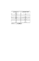
図7は、定着部40の温度制御を行っていないときの定着部温度とその温度から温度制御を開始してから目標温度(200℃)までの到達時間の関係を示す図である。この関係を示すデータはROM251に格納されている。スタンバイモード時に定着部40を温度制御している場合には常に目標温度(画像形成時に必要な温度)に制御している。しかしながら省電力モードの場合もしくはスタンバイモードでも温度制御をしていない場合は、画像形成の開始の指示があると定着部40の温度を目標温度まで立ち上げなければならない。この場合、前回の画像形成による影響で定着部40が暖まっている場合、目標温度に到達するまでの時間が変わってくる。例えば、図6で前述したように500枚の画像形成後300秒経過した時点で、定着部40は100℃に達する。その時点で画像形成開始(温度制御開始)命令がきた場合、定着部40が目標温度(200℃)に到達するまでに、10秒必要である事がわかる。定着部40の温度が更に低い場合には定着目標温度への到達時間が更に長くなる。   FIG. 7 is a diagram illustrating the relationship between the fixing unit temperature when the temperature control of the fixing unit 40 is not performed and the arrival time from the temperature control start to the target temperature (200 ° C.). Data indicating this relationship is stored in the ROM 251. When the temperature of the fixing unit 40 is controlled in the standby mode, the temperature is always controlled to the target temperature (temperature necessary for image formation). However, when the temperature control is not performed even in the power saving mode or in the standby mode, the temperature of the fixing unit 40 must be raised to the target temperature when an instruction to start image formation is given. In this case, when the fixing unit 40 is warmed due to the influence of the previous image formation, the time until the target temperature is reached varies. For example, as described above with reference to FIG. 6, the fixing unit 40 reaches 100 ° C. when 300 seconds have elapsed after forming 500 images. If an image formation start (temperature control start) command is issued at that time, it is understood that 10 seconds are required until the fixing unit 40 reaches the target temperature (200 ° C.). When the temperature of the fixing unit 40 is lower, the time to reach the fixing target temperature is further increased.

定着部40以外の要素の起動時間、例えばメインコントローラ202(CPU250)が制御可能な状態に立ち上がるのに要する時間(立ち上がり時間)は10秒であるとする。省電力モードになっている時に画像形成開始命令がきた際に、メインコントローラ202(CPU250)の立ち上がり時間よりも定着部40が目標温度になるまでの時間が短ければ、メインコントローラ202の立ち上がり直後に画像形成を開始できる。即ち、定着部40の温度が所定温度(本例では100℃)以上であれば、目標温度に到達するまでの時間が10秒以下となるので、メインコントローラ202の起動直後に画像形成が開始できる。しかし、定着部40の温度が100℃未満である場合、メインコントローラ202が立ち上がったとしても、定着部40が目標温度に到達していないため、直ちに画像形成を開始できない。即ち、画像形成終了後に定着部40の温度が100℃未満に低下した場合は、省電力モードへ移行してもスタンバイモードのままであっても、画像形成を開始できるようになるまでの時間は同じになる。   It is assumed that the activation time of elements other than the fixing unit 40, for example, the time required for the main controller 202 (CPU 250) to rise to a controllable state (rise time) is 10 seconds. If the time until the fixing unit 40 reaches the target temperature is shorter than the rise time of the main controller 202 (CPU 250) when an image formation start command is received in the power saving mode, immediately after the main controller 202 rises. Image formation can be started. That is, if the temperature of the fixing unit 40 is equal to or higher than a predetermined temperature (100 ° C. in this example), the time until the target temperature is reached is 10 seconds or less, so that image formation can be started immediately after the main controller 202 is activated. . However, when the temperature of the fixing unit 40 is less than 100 ° C., even if the main controller 202 is started up, the fixing unit 40 has not reached the target temperature, so that image formation cannot be started immediately. That is, when the temperature of the fixing unit 40 decreases to less than 100 ° C. after the image formation is completed, the time until the image formation can be started even when the mode is shifted to the power saving mode or the standby mode is maintained. Be the same.

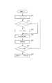
図8のフローチャートを用いて、本実施形態における省電力モード移行の制御に関して説明する。このフローチャートは、メインコントローラ202に配置されるCPU250がROM251内に格納されているプログラムに従って実行する。   With reference to the flowchart of FIG. 8, the control for shifting to the power saving mode in the present embodiment will be described. This flowchart is executed according to a program stored in the ROM 251 by the CPU 250 arranged in the main controller 202.

画像形成装置の電源がON或いは省電力モードから復帰され、メインコントローラ202(CPU250)が立ち上がると、CPU250はモジュール制御部201に、前多回転などの画像形成部のイニシャル動作を行わせるよう制御する(1002)。CPU250は、イニシャル動作が終了すると、スタンバイモードに移行してプリント要求を待つ(1003)。プリント要求がない場合は、CPU250はサーミスタ712の出力に基づいて定着部40の温度検知を行う(1005)。CPU250は、検知した温度から算出される定着部40の目標温度到達時間と省電力モードからの復帰に要する時間(メインコントローラ202の起動時間10秒)との比較を行う(1006)。この比較はROM251に格納されているテーブル(図7)に基づいて行われる。CPU250は、定着部40の目標温度到達時間が10秒以下すなわち定着部40の温度が100℃以上かどうかを判断し(1007)、100℃以上である場合は、スタンバイモードを維持する(1003〜1007を繰り返す)。CPU250は、スタンバイモード中は常に定着部40の温度の監視を行い、画像形成終了後からの経過時間とは関係なく、100℃未満になったら省電力モードに移行する処理を行い、画像形成装置を省電力モードに移行する(1008)。この100℃という温度は、定着部40が検知温度から目標温度に到達するまでに要する時間が、メインコントローラ202が省電力モードから復帰する際の立ち上がり時間よりも短くならない温度(検知温度)である。   When the power source of the image forming apparatus is turned on or restored from the power saving mode and the main controller 202 (CPU 250) is started up, the CPU 250 controls the module control unit 201 to perform the initial operation of the image forming unit such as pre-multi rotation. (1002). When the initial operation ends, the CPU 250 shifts to the standby mode and waits for a print request (1003). If there is no print request, the CPU 250 detects the temperature of the fixing unit 40 based on the output of the thermistor 712 (1005). The CPU 250 compares the target temperature arrival time of the fixing unit 40 calculated from the detected temperature with the time required for returning from the power saving mode (the startup time of the main controller 202 is 10 seconds) (1006). This comparison is performed based on a table (FIG. 7) stored in the ROM 251. The CPU 250 determines whether the target temperature arrival time of the fixing unit 40 is 10 seconds or less, that is, whether the temperature of the fixing unit 40 is 100 ° C. or higher (1007). Repeat 1007). The CPU 250 always monitors the temperature of the fixing unit 40 during the standby mode, performs a process of shifting to the power saving mode when the temperature becomes less than 100 ° C., regardless of the elapsed time after the end of image formation, and the image forming apparatus. Is shifted to the power saving mode (1008). The temperature of 100 ° C. is a temperature (detection temperature) at which the time required for the fixing unit 40 to reach the target temperature from the detection temperature is not shorter than the rise time when the main controller 202 returns from the power saving mode. .

CPU250はステップ1003で、プリント要求があったことを判断した場合は、プリント動作を行い(1004)、プリント終了後に定着部40の温度制御を終了した後も上述したステップ1005以降の処理を行う。ステップ1004のプリント動作で、例えば500枚の画像形成が行われた場合は、およそ5分後に定着部40の温度が100℃に低下するので、省電力モードへ移行することになる。また、ステップ1004のプリント動作で50枚の画像形成が行われた場合は、およそ1分後に省電力モードへ移行することになる。どちらの場合も省電力モードへ移行する前、すなわちスタンバイモード時には、画像形成開始の指示を入力してから10秒以内にファーストプリントを出力することが可能である。   If the CPU 250 determines in step 1003 that a print request has been made, the CPU 250 performs a printing operation (1004), and performs the processing in and after step 1005 described above even after finishing the temperature control of the fixing unit 40 after the printing. If, for example, 500 images are formed in the printing operation in step 1004, the temperature of the fixing unit 40 decreases to 100 ° C. after about 5 minutes, so that the mode is shifted to the power saving mode. If 50 images are formed in the printing operation in step 1004, the mode is shifted to the power saving mode after about 1 minute. In either case, before shifting to the power saving mode, that is, in the standby mode, it is possible to output the first print within 10 seconds after inputting the instruction to start image formation.

省電力モードへ移行すると、CPU250は、操作部もしくはネットワーク等から立上げ要求(プリント要求など)が来るのを監視するために通信部204のみに電力を供給する様に電力制御部を制御する(1008)。その後、CPU250への電力供給が遮断される。通信部204は省電力モード中、前記操作部やネットワーク等から画像形成装置の立上げ要求の有無を監視し、立上げ要求が来ると、電力制御部203へCPU250等を立ち上げるための電力供給の指示を出力する。これにより、CPU250を含むメインコントローラ202に電力が供給され、画像形成装置を画像形成可能な状態に立ち上げる。   When the mode is shifted to the power saving mode, the CPU 250 controls the power control unit so as to supply power only to the communication unit 204 in order to monitor the start-up request (print request or the like) from the operation unit or the network. 1008). Thereafter, the power supply to the CPU 250 is cut off. During the power saving mode, the communication unit 204 monitors whether or not the image forming apparatus is requested to start up from the operation unit or the network. When the startup request is received, the power supply unit 203 supplies power to start up the CPU 250 and the like. Is output. As a result, power is supplied to the main controller 202 including the CPU 250, and the image forming apparatus is brought into a state where image formation is possible.

なお、本制御は画像形成装置が電源オフ或いは省電力モードへ移行されるまで繰り返し行われる。   This control is repeatedly performed until the image forming apparatus is turned off or shifted to the power saving mode.

以上の様に、メインコントローラ202の立ち上がりに要する時間と定着部40の定着可能温度への復帰に要する時間とを考慮して、省電力モードへ移行するタイミングを決定することにより、省電力モードからの復帰を効率良く行うことができる。即ち、大量プリント後などで定着器が温かい状態であるにも関わらず省電力モードへ移行してしまい、省電力モードからの復帰後のファーストプリント時間が長くなることを防止できる。   As described above, by considering the time required for the main controller 202 to rise and the time required for the fixing unit 40 to return to the fixable temperature, the timing for shifting to the power saving mode is determined. Can be efficiently performed. That is, it is possible to prevent the first print time after returning from the power saving mode from becoming long because the fixing device is in a warm state after a large amount of printing.

本実施形態では、定着部40のヒータ部にセラミックヒータ(抵抗体)を用いた場合を例に説明を行ったがハロゲンヒータ、IHヒータなどを用いた定着部であっても良い。   In this embodiment, the case where a ceramic heater (resistor) is used as the heater unit of the fixing unit 40 has been described as an example. However, a fixing unit using a halogen heater, an IH heater, or the like may be used.

また、省電力状態からの立上げ要求は、操作部やネットワークからの要求以外に、FAX、USB接続可能な装置であっても良い、
また、本実施形態では、定着部40の温度から目標到達温度を予測するテーブルを用いている。しかし、図6に示す画像形成終了後の定着部40の温度の複数の立下り特性と測定された定着部40の温度から目標温度到達時間を予測するテーブルを用いても良い。例えば、直前の画像形成ジョブにおける像形成枚数が所定枚数以上の場合と未満の場合とで図7に示すテーブルを別々に設けるようにすればよい。即ち、直前の画像形成ジョブの継続時間に応じて、定着部40の目標温度到達時間が変更されることになる。例えば、検知した定着部の温度を100℃とした場合、直前の画像形成ジョブの継続時間が第1の時間T1のときの目標温度到達時間は、直前の画像形成ジョブの継続時間が第2の時間T2(<T1)のときの目標温度到達時間よりも短くなる。この理由は直前の画像形成ジョブの継続時間がT1のときの加圧ローラ703の蓄熱量がT2のときよりも多いからである。そこで、直前の画像形成ジョブの継続時間がT1のときの省電力モードへ移行する温度を継続時間がT2のときよりも低くする。画像形成ジョブの継続時間を像形成枚数と置き換えても同様である。
In addition, the startup request from the power saving state may be a device that can be connected by FAX or USB in addition to a request from the operation unit or the network.
In this embodiment, a table that predicts the target temperature from the temperature of the fixing unit 40 is used. However, a table for predicting the target temperature arrival time from the plurality of falling characteristics of the fixing unit 40 after the end of image formation and the measured temperature of the fixing unit 40 shown in FIG. 6 may be used. For example, the table shown in FIG. 7 may be provided separately for the case where the number of image formations in the immediately preceding image formation job is greater than or equal to the predetermined number. That is, the target temperature arrival time of the fixing unit 40 is changed according to the duration of the immediately preceding image forming job. For example, when the detected temperature of the fixing unit is 100 ° C., the target temperature arrival time when the duration of the immediately preceding image forming job is the first time T1 is the second duration of the immediately preceding image forming job. It becomes shorter than the target temperature arrival time at time T2 (<T1). This is because the amount of heat stored in the pressure roller 703 when the duration of the immediately preceding image forming job is T1 is greater than when the duration is T2. Therefore, the temperature for shifting to the power saving mode when the duration of the immediately preceding image forming job is T1 is set lower than when the duration is T2. The same applies even if the duration of the image forming job is replaced with the number of images formed.

また、本実施形態では、省電力モードへの移行タイミングを、定着部40の目標温度到達時間とメインコントローラ202の省電力モードからの復帰時間の比較により決定していた。しかし、これに加えて、ユーザが省電力モードへの移行時間を設定できるようにしても良い。これにより、例えば、多量の画像形成が行われて、定着部40の温度低下が遅くなり、省電力モードへの移行するタイミング遅くなるような場合でも、ユーザが設定した移行時間で省電力モードへ移行することで、省電力モードへの移行時間が長くなりすぎない。   In the present embodiment, the timing for shifting to the power saving mode is determined by comparing the target temperature arrival time of the fixing unit 40 and the return time of the main controller 202 from the power saving mode. However, in addition to this, the user may be able to set the transition time to the power saving mode. Thus, for example, even when a large amount of image formation is performed, the temperature drop of the fixing unit 40 is delayed, and the timing of shifting to the power saving mode is delayed, the mode is changed to the power saving mode with the transition time set by the user. By shifting, the transition time to the power saving mode does not become too long.

画像形成装置の側断面図である。1 is a side sectional view of an image forming apparatus. 画像形成装置の制御ブロック図である。2 is a control block diagram of the image forming apparatus. FIG. 定着部の構成図である。It is a block diagram of a fixing unit. ヒータの平面図である。It is a top view of a heater. ヒータ駆動回路を示す図である。It is a figure which shows a heater drive circuit. 定着部の温度推移を示す図である。It is a figure which shows the temperature transition of a fixing part. 定着部温度と省電力モードからの復帰後の目標温度到達時間の関係を示した図である。FIG. 6 is a diagram illustrating a relationship between a fixing unit temperature and a target temperature arrival time after returning from a power saving mode. 省電力モードへの移行制御を示すフローチャートである。It is a flowchart which shows transfer control to a power saving mode.

符号の説明Explanation of symbols

40 定着部
202 メインコントローラ
203 電力制御部
204 通信部
250 CPU
712 サーミスタ
40 Fixing Unit 202 Main Controller 203 Power Control Unit 204 Communication Unit 250 CPU
712 thermistor

Claims (5)

画像形成が実行されていない状態の消費電力を低減させる省電力モードを有する画像形成装置において、
シートに画像を形成する像形成手段と、
画像が形成されたシートを定着する定着部と、
前記定着部の温度を検出する温度検出手段と、
前記定着部の温度を目標温度となる様に制御する温度制御手段と、
画像形成終了後の前記温度検出手段により検出された温度が所定温度よりも低くなると前記画像形成装置を前記省電力モードへ移行させる制御部と、
を有することを特徴とする画像形成装置。
In an image forming apparatus having a power saving mode for reducing power consumption when image formation is not performed,
Image forming means for forming an image on a sheet;
A fixing unit for fixing a sheet on which an image is formed; and
Temperature detecting means for detecting the temperature of the fixing unit;
Temperature control means for controlling the temperature of the fixing unit to be a target temperature;
A control unit that shifts the image forming apparatus to the power saving mode when the temperature detected by the temperature detecting unit after image formation is lower than a predetermined temperature;
An image forming apparatus comprising:
前記所定温度は、前記温度検出手段により検出された温度から前記目標温度に到達するまでに要する時間が、前記省電力モードから復帰する際の前記制御部の立ち上がりに要する時間よりも長くなるような温度であることを特徴とする請求項1記載の画像形成装置。   The predetermined temperature is such that the time required to reach the target temperature from the temperature detected by the temperature detection means is longer than the time required for the controller to start up when returning from the power saving mode. The image forming apparatus according to claim 1, wherein the image forming apparatus is a temperature. 前記制御部は、前記定着部の温度と、該温度から前記目標温度に到達するのに要する時間との関係を示すデータを記憶したテーブルを有することを特徴とする請求項2記載の画像形成装置。   The image forming apparatus according to claim 2, wherein the control unit includes a table storing data indicating a relationship between a temperature of the fixing unit and a time required to reach the target temperature from the temperature. . 画像形成開始の指示を監視する監視部を有し、前記省電力モードの状態では、前記監視部には電力供給され、前記制御部には電力供給されないことを特徴とする請求項1記載の画像形成装置。   The image according to claim 1, further comprising a monitoring unit that monitors an instruction to start image formation, wherein in the power saving mode, power is supplied to the monitoring unit and power is not supplied to the control unit. Forming equipment. 前記制御部は、直前の画像形成ジョブの継続時間が第1の時間の場合に、直前の画像形成ジョブの継続時間が前記第1の時間よりも短い第2の時間の場合よりも、前記所定温度を低くすることを特徴とする請求項1記載の画像形成装置。   When the duration of the immediately preceding image forming job is the first time, the control unit performs the predetermined time more than when the duration of the immediately preceding image forming job is the second time shorter than the first time. The image forming apparatus according to claim 1, wherein the temperature is lowered.
JP2008295797A 2008-11-19 2008-11-19 Image forming apparatus Pending JP2010122448A (en)

Priority Applications (1)

Application Number Priority Date Filing Date Title
JP2008295797A JP2010122448A (en) 2008-11-19 2008-11-19 Image forming apparatus

Applications Claiming Priority (1)

Application Number Priority Date Filing Date Title
JP2008295797A JP2010122448A (en) 2008-11-19 2008-11-19 Image forming apparatus

Publications (2)

Publication Number Publication Date
JP2010122448A true JP2010122448A (en) 2010-06-03
JP2010122448A5 JP2010122448A5 (en) 2012-01-12

Family

ID=42323851

Family Applications (1)

Application Number Title Priority Date Filing Date
JP2008295797A Pending JP2010122448A (en) 2008-11-19 2008-11-19 Image forming apparatus

Country Status (1)

Country Link
JP (1) JP2010122448A (en)

Cited By (2)

* Cited by examiner, † Cited by third party
Publication number Priority date Publication date Assignee Title
JP2012139927A (en) * 2010-12-29 2012-07-26 Ricoh Co Ltd Image processing apparatus and image forming apparatus
US9261947B2 (en) 2011-02-23 2016-02-16 Ricoh Company, Ltd. Device and power saving control method for selectively transitioning to one or more low power modes depending on whether all of the programs on the device have been interrupted or terminated

Citations (2)

* Cited by examiner, † Cited by third party
Publication number Priority date Publication date Assignee Title
JPH09185299A (en) * 1995-10-30 1997-07-15 Fuji Xerox Co Ltd Image forming device
JP2007322708A (en) * 2006-05-31 2007-12-13 Kyocera Mita Corp Image forming apparatus

Patent Citations (2)

* Cited by examiner, † Cited by third party
Publication number Priority date Publication date Assignee Title
JPH09185299A (en) * 1995-10-30 1997-07-15 Fuji Xerox Co Ltd Image forming device
JP2007322708A (en) * 2006-05-31 2007-12-13 Kyocera Mita Corp Image forming apparatus

Cited By (2)

* Cited by examiner, † Cited by third party
Publication number Priority date Publication date Assignee Title
JP2012139927A (en) * 2010-12-29 2012-07-26 Ricoh Co Ltd Image processing apparatus and image forming apparatus
US9261947B2 (en) 2011-02-23 2016-02-16 Ricoh Company, Ltd. Device and power saving control method for selectively transitioning to one or more low power modes depending on whether all of the programs on the device have been interrupted or terminated

Similar Documents

Publication Publication Date Title
US8311431B2 (en) Image forming apparatus comprising a control section configured to carry out a control process including setting a power saving mode
JP5058669B2 (en) Image forming apparatus
JP4403136B2 (en) FIXING DEVICE, IMAGE FORMING DEVICE EQUIPPED WITH THE FIXING DEVICE, AND CONTROL METHOD FOR FIXING DEVICE
JP2004126191A (en) Image forming apparatus
JP5488861B2 (en) Image forming apparatus and method for controlling warm-up time in image forming apparatus
JP5625861B2 (en) Image forming apparatus and fixing control method
JP4283764B2 (en) POWER CONTROL DEVICE, HEATING DEVICE, FIXING DEVICE, IMAGE FORMING DEVICE, POWER CONTROL METHOD, AND POWER CONTROL PROGRAM
JP2012128189A (en) Image forming apparatus and temperature control method for fixing device
JP2000330426A (en) Electrophotographic device
JP2010122448A (en) Image forming apparatus
US9477184B2 (en) Image forming apparatus controlling temperature of fixing portion in image formation mode and in standby modes
JP5595090B2 (en) Image forming apparatus and fixing device control method
JP4539706B2 (en) Image forming apparatus and image forming method
JP2012118228A (en) Image forming apparatus
JP2009063725A (en) Image forming device
JP2011033808A (en) Image forming apparatus
JP2004126173A (en) Image forming apparatus
JP2004133216A (en) Color image forming apparatus
JP6305208B2 (en) Fixing apparatus and image forming apparatus
JPH10133465A (en) Color electrophotographic device
JP2022181270A (en) Image forming apparatus
JP2005241660A (en) Image forming apparatus
JP2022162834A (en) Fixing device and image forming apparatus including the same
JP6074960B2 (en) Heating control apparatus, image forming apparatus, and heating control method
JP2022042637A (en) Image forming device and control method

Legal Events

Date Code Title Description
RD01 Notification of change of attorney

Free format text: JAPANESE INTERMEDIATE CODE: A7421

Effective date: 20100630

A521 Written amendment

Free format text: JAPANESE INTERMEDIATE CODE: A523

Effective date: 20111121

A621 Written request for application examination

Free format text: JAPANESE INTERMEDIATE CODE: A621

Effective date: 20111121

A977 Report on retrieval

Free format text: JAPANESE INTERMEDIATE CODE: A971007

Effective date: 20121112

A131 Notification of reasons for refusal

Free format text: JAPANESE INTERMEDIATE CODE: A131

Effective date: 20121120

A02 Decision of refusal

Free format text: JAPANESE INTERMEDIATE CODE: A02

Effective date: 20130312