JP5594058B2 - Game machine - Google Patents
Game machine Download PDFInfo
- Publication number
- JP5594058B2 JP5594058B2 JP2010238220A JP2010238220A JP5594058B2 JP 5594058 B2 JP5594058 B2 JP 5594058B2 JP 2010238220 A JP2010238220 A JP 2010238220A JP 2010238220 A JP2010238220 A JP 2010238220A JP 5594058 B2 JP5594058 B2 JP 5594058B2
- Authority
- JP
- Japan
- Prior art keywords
- control board
- clear
- payout control
- main control
- switch
- Prior art date
- Legal status (The legal status is an assumption and is not a legal conclusion. Google has not performed a legal analysis and makes no representation as to the accuracy of the status listed.)
- Expired - Lifetime
Links
Images


Description
本発明は、パチンコ機やスロットマシンに代表される遊技機に関するものである。 The present invention relates to a gaming machine typified by a pachinko machine or a slot machine.
パチンコ機の遊技の制御は、主に主制御基板により行われる。この主制御基板には、賞球や貸し球の払い出し制御を行う払出制御基板や、効果音の出力制御を行う効果音制御基板、図柄の変動表示等の表示制御を行う表示用制御基板などが接続されている。これら各制御基板の制御は、主制御基板から各制御基板へ一方向に送信されるコマンドにより行われる。 Control of pachinko machine games is mainly performed by the main control board. The main control board includes a payout control board that performs payout control of prize balls and rental balls, a sound effect control board that performs output control of sound effects, and a display control board that performs display control such as symbol variation display. It is connected. The control of each control board is performed by a command transmitted from the main control board to each control board in one direction.
賞球の払い出しは、停電等の発生によってパチンコ機の電源が突然切断された場合にも確実に行う必要がある。そこで、本願出願人は、払出のデータをパチンコ機の電源が切断された後も保持して(バックアップして)、電源が再投入された後に未払い分の賞球を払い出すことを試みた。 The payout of the prize ball must be surely performed even when the power of the pachinko machine is suddenly cut off due to the occurrence of a power failure or the like. Therefore, the present applicant is also retained after the data of the dispensing power of the pachinko machine is disconnected (back up), tried to pay out unpaid of prize balls after the power is restored.
しかしながら、パチンコ機の払出データをバックアップしていると、パチンコ機の電源が再投入されたときに、常に未払いの賞球が払い出されてしまうという問題点がある。 However, we are backing the payout data pachinko, when the power of the pachinko machine is turned on again, there is always a problem that unpaid winning balls will be paid out.
本発明は上述した問題点を解決するためになされたものであり、賞球の払い出し残数をバックアップしつつ、そのバックアップした内容をクリアすることができる遊技機を提供することを目的としている。 The present invention has been made to solve the above-described problems, and an object of the present invention is to provide a gaming machine capable of clearing the backed up content while backing up the remaining number of award balls .
この目的を達成するために請求項1記載の遊技機は、遊技の制御を行う主制御基板と、その主制御基板から送信されるコマンドに基づいて所定の制御を行うサブ制御基板と、前記主制御基板およびサブ制御基板へ駆動電力を供給する電源基板と、押下式操作スイッチと、を備え、前記主制御基板は、少なくとも有価物体の払出残数情報を記憶すると共に、その記憶した払出残数情報を電源の切断後においても保持可能な記憶手段と、その記憶手段の内容をクリアするクリア処理手段と、そのクリア処理手段によって前記記憶手段に記憶される内容をクリアする場合に、前記サブ制御基板にクリア時コマンドを出力するコマンド出力手段と、を備え、前記サブ制御基板は、前記クリア時コマンドを受信した場合に、そのクリア時コマンドに対応した制御を行うものであり、そのクリア時コマンドに対応した制御を行った場合に初期状態にリセットされず、前記クリア処理手段は、前記押下式操作スイッチが押下操作された状態で、電源が所定状態に切り替えられた場合に、前記記憶手段に記憶される内容をクリアし、前記記憶手段は、バックアップ用コンデンサによって電源の切断後においても記憶内容を保持可能であり、該保持される記憶内容は、前記払出残数情報以外の情報を含む記憶内容である。
In order to achieve this object, a gaming machine according to claim 1 includes a main control board that controls a game, a sub control board that performs predetermined control based on a command transmitted from the main control board, and the main control board. A power supply board for supplying driving power to the control board and the sub-control board, and a push-down operation switch, wherein the main control board stores at least the payout remaining number information of the valuable object, and the stored payout remaining number The sub-control when the storage means capable of holding the information even after the power is turned off, the clear processing means for clearing the contents of the storage means, and the contents stored in the storage means by the clear processing means are cleared. Command output means for outputting a clear command to the board, and the sub-control board responds to the clear command when the clear command is received. A row Umono control was not reset to the initial state when performing control corresponding to the clear time of the command, the clear processing unit, in a state where the press-type operation switch is pressed, power is When the state is switched to a predetermined state, the content stored in the storage unit is cleared, and the storage unit can hold the stored content even after the power supply is cut off by the backup capacitor. Is stored contents including information other than the payout remaining number information.
本発明の遊技機によれば、遊技の制御を行う主制御基板と、その主制御基板から送信されるコマンドに基づいて所定の制御を行うサブ制御基板と、前記主制御基板およびサブ制御基板へ駆動電力を供給する電源基板と、押下式操作スイッチと、を備え、前記主制御基板は、少なくとも有価物体の払出残数情報を記憶すると共に、その記憶した払出残数情報を電源の切断後においても保持可能な記憶手段と、その記憶手段の内容をクリアするクリア処理手段と、そのクリア処理手段によって前記記憶手段に記憶される内容をクリアする場合に、前記サブ制御基板にクリア時コマンドを出力するコマンド出力手段と、を備え、前記サブ制御基板は、前記クリア時コマンドを受信した場合に、そのクリア時コマンドに対応した制御を行うものであり、そのクリア時コマンドに対応した制御を行った場合に初期状態にリセットされず、前記クリア処理手段は、前記押下式操作スイッチが押下操作された状態で、電源が所定状態に切り替えられた場合に、前記記憶手段に記憶される内容をクリアし、前記記憶手段は、バックアップ用コンデンサによって電源の切断後においても記憶内容を保持可能であり、該保持される記憶内容は、前記払出残数情報以外の情報を含む記憶内容であるので、記憶手段の内容をクリアすることができるという効果がある。
According to the gaming machine of the present invention, a main control board that controls the game, a sub control board that performs predetermined control based on a command transmitted from the main control board, and the main control board and the sub control board A power supply board for supplying drive power; and a push-type operation switch, wherein the main control board stores at least the payout remaining number information of the valuable object, and the stored payout remaining number information after the power is turned off. Storage means that can also hold, a clear processing means for clearing the contents of the storage means, and a clear command to output a clear command to the sub control board when the contents stored in the storage means are cleared by the clear processing means and a command output means for, the sub-control board, when receiving the clear time command, there a control corresponding to the clear time of command line Umono Its not reset to the initial state when performing control corresponding to the clear time of the command, the clear processing unit, in a state where the press-type operation switch is pressed, when the power supply is switched to a predetermined state, The content stored in the storage means is cleared, and the storage means can retain the stored content even after the power is cut off by a backup capacitor, and the stored content is other than the payout remaining number information. Since the stored contents include information, the contents of the storage means can be cleared.
以下、本発明の好ましい実施例について、添付図面を参照して説明する。本実施例では、遊技機の一例として弾球遊技機の一種であるパチンコ機、特に、第1種パチンコ遊技機を用いて説明する。なお、本発明を第3種パチンコ遊技機や、コイン遊技機、スロットマシン等の他の遊技機に用いることは、当然に可能である。 Hereinafter, preferred embodiments of the present invention will be described with reference to the accompanying drawings. In this embodiment, a pachinko machine that is a kind of a ball game machine, in particular, a first type pachinko game machine will be described as an example of the game machine. Of course, the present invention can be used for other gaming machines such as a third-class pachinko gaming machine, a coin gaming machine, and a slot machine.
図1は、本実施例のパチンコ機Pの遊技盤の正面図である。遊技盤1の周囲には、球が入賞することにより5個から15個の球が払い出される複数の入賞口2が設けられている。また、遊技盤1の中央には、複数種類の識別情報としての図柄などを表示する液晶(LCD)ディスプレイ3が設けられている。このLCDディスプレイ3の表示画面は横方向に3分割されており、3分割された各表示領域において、それぞれ右から左へ横方向にスクロールしながら図柄の変動表示が行われる。
FIG. 1 is a front view of a game board of a pachinko machine P according to the present embodiment. Around the game board 1, there are provided a plurality of winning
LCDディスプレイ3の下方には、図柄作動口(第1種始動口)4が設けられ、球がこの図柄作動口4を通過することにより、前記したLCDディスプレイ3の変動表示が開始される。図柄作動口4の下方には、特定入賞口(大入賞口)5が設けられている。この特定入賞口5は、LCDディスプレイ3の変動後の表示結果が予め定められた図柄の組み合わせの1つと一致する場合に、大当たりとなって、球が入賞しやすいように所定時間(例えば、30秒経過するまで、あるいは、球が10個入賞するまで)開放される。
Below the
この特定入賞口5内には、Vゾーン5aが設けられており、特定入賞口5の開放中に、球がVゾーン5a内を通過すると、継続権が成立して、特定入賞口5の閉鎖後、再度、その特定入賞口5が所定時間(又は、特定入賞口5に球が所定個数入賞するまで)開放される。この特定入賞口5の開閉動作は、最高で16回(16ラウンド)繰り返し可能にされており、開閉動作の行われ得る状態が、いわゆる所定の遊技価値の付与された状態(特別遊技状態)である。
A V
図2は、パチンコ機Pの電気的構成を示したブロック図であり、特に、パチンコ機Pの遊技内容の制御を行う主制御基板Cと、賞球や貸し球の払出制御を行う払出制御基板Hとの電気的構成を示したブロック図である。 FIG. 2 is a block diagram showing the electrical configuration of the pachinko machine P, and in particular, a main control board C that controls the game contents of the pachinko machine P, and a payout control board that performs payout control of prize balls and rental balls. It is the block diagram which showed the electric constitution with H.
パチンコ機Pの主制御基板Cは、演算装置であるMPU11と、そのMPU11により実行される各種の制御プログラムや固定値データ等を記憶したROM12と、ワークメモリ等として使用されるRAM13とを備えている。図4のフローチャートに示すプログラムは、制御プログラムの一部としてROM12内に記憶されている。またRAM13には、賞球バッファ13aと、賞球ポインタ13bと、残賞球数カウンタ13cとが設けられている。
The main control board C of the pachinko machine P includes an
賞球バッファ13aは、遊技領域1へ打ち込まれた球が普通入賞口2等へ入賞した場合に、払い出される賞球数を記憶するバッファである。払い出される賞球数は入賞した球毎に賞球バッファ13aへ記憶されるので、賞球バッファ13aは複数バイトで構成されている。賞球バッファ13aに記憶された賞球数のデータは、賞球コマンドとして払出制御基板Hへ送信されると、賞球バッファ13aから消去される。具体的には、0番目の賞球バッファ13aに記憶される賞球数を払出制御基板Hへ送信した後、1番目以降の賞球バッファ13aの値を小さいアドレス側へ順に1バイトずつシフトすることにより、0番目の賞球バッファ13aの値が消去される。
The winning
なお、賞球コマンドとは、払い出される賞球数を払出制御基板Hへ指示するためのコマンドであり、1回の入賞に対する最大の賞球数が15球であるので、その最大賞球数に対応した「01H」〜「0FH」の15種類の賞球コマンドが用意されている。 The prize ball command is a command for instructing the payout control board H of the number of prize balls to be paid out. Since the maximum number of prize balls for one winning is 15 balls, Corresponding 15 types of prize ball commands “01H” to “0FH” are prepared.
賞球ポインタ13bは、賞球数を記憶させる賞球バッファ13aの位置を示すポインタであり、払い出される賞球数は、賞球ポインタ13bの値番目の賞球バッファ13aへ記憶される。この賞球ポインタ13bの値は、賞球バッファ13aへ賞球数を書き込むことにより「1」加算され、逆に、0番目の賞球バッファ13aの値が払出制御基板Hへ送信されることにより「1」減算される。
The prize ball pointer 13b is a pointer indicating the position of the
残賞球数カウンタ13cは、未払いの賞球数を記憶するカウンタであり、払出制御基板Hによって払い出される賞球数を主制御基板Cで管理するためのカウンタである。残賞球数カウンタ13cの値は、主制御基板Cが払出制御基板Hへ賞球の払い出しを指示する毎に、その指示した数が加算され、逆に、払出制御基板Hによって賞球の払い出しが行われて、その払い出された賞球を賞球カウントスイッチ22が検出する毎に「1」ずつ減算される。
The remaining prize ball number counter 13c is a counter for storing the number of unpaid prize balls, and is a counter for managing the number of prize balls to be paid out by the payout control board H on the main control board C. Each time the main control board C instructs the payout control board H to pay out the prize ball, the value of the remaining prize ball counter 13c is incremented, and conversely, the payout control board H pays out the prize ball. Each time the award
これらMPU11、ROM12、RAM13は、アドレスバス及びデータバスで構成されるバスライン14を介して相互に接続されている。バスライン14は、また、入出力ポート15にも接続されている。入出力ポート15は、入力および出力が固定的なバッファ(インバータゲート)16,37を介して払出制御基板Hと接続されるほか、複数の普通入賞スイッチ17と、第1種始動口スイッチ18と、Vカウントスイッチ19と、10カウントスイッチ20と、賞球カウントスイッチ22と、他の入出力装置25と、それぞれ接続されている。
The
普通入賞スイッチ17は、遊技領域1内の複数の普通入賞口2へ入賞した球をそれぞれ検出するためのスイッチであり、各普通入賞口2の入口近傍に設けられている。第1種始動口スイッチ18は、図柄作動口(第1種始動口)4を通過した球を検出するためのスイッチであり、図柄作動口4の近傍に設けられている。普通入賞スイッチ17のいずれか又は第1種始動口スイッチ18によって球が検出されると、払出制御基板Hによって6個の賞球が払い出される。Vカウントスイッチ19は、特定入賞口5内のVゾーン5aへ入賞した球を検出するためのスイッチであり、また、10カウントスイッチ20は、特定入賞口5内のVゾーン5a以外へ入賞した球を検出するためのスイッチである。Vカウントスイッチ19又は10カウントスイッチ20により球が検出されると、払出制御基板Hによって15個の賞球が払い出される。
The
賞球カウントスイッチ22は、賞球払出用モータ21によって払い出された賞球を検出するためのスイッチであり、賞球払出用モータ21と共に賞球払出ユニットSに搭載されている。賞球払出用モータ21は賞球を払い出すためのモータであり、賞球払出用モータ21の駆動は、払出制御基板Hによって制御される。
The prize
前記した通り主制御基板Cは、入力および出力が固定的なバッファ(インバータゲート)16,37を介して、払出制御基板Hと接続されている。このため主制御基板Cと払出制御基板Hとの間における賞球コマンド等の送受信は、主制御基板Cから払出制御基板Hへの一方向にのみ行われ、払出制御基板Hから主制御基板Cへ行うことはできない。なお、主制御基板Cと払出制御基板Hとは、8本のデータ線と1本のストローブ線とにより接続されており、ストローブ線のデータがアクティブになった時に、8本のデータ線上に出力されているデータが主制御基板Cから払出制御基板Hへコマンドとして送信される。 As described above, the main control board C is connected to the payout control board H via the buffers (inverter gates) 16 and 37 whose inputs and outputs are fixed. Therefore, transmission / reception of a prize ball command or the like between the main control board C and the payout control board H is performed only in one direction from the main control board C to the payout control board H, and the payout control board H to the main control board C. Can not be done. The main control board C and the payout control board H are connected by eight data lines and one strobe line, and when the data on the strobe line becomes active, the data is output onto the eight data lines. The transmitted data is transmitted from the main control board C to the payout control board H as a command.
払出制御基板Hは賞球や貸し球の払出制御を行うものであり、演算装置であるMPU31と、そのMPU31により実行される制御プログラムや固定値データ等を記憶したROM32と、ワークメモリ等として使用されるRAM33とを備えている。図5及び図6に示すフローチャートのプログラムは、制御プログラムの一部としてROM32内に記憶されている。
The payout control board H performs payout control of prize balls and lending balls, and is used as an
払出制御基板HのRAM33は、残賞球数カウンタ33aを備えると共に、バックアップ用のコンデンサ33bが接続されてバックアップ可能に構成されている。よって、RAM33の残賞球数カウンタ33aの値は、パチンコ機Pの電源が切断された場合にも保持されるのである。
The
残賞球数カウンタ33aは、前述した主制御基板Cの残賞球数カウンタ13cと同様に、未払いの賞球数を記憶するカウンタである。残賞球数カウンタ33aの値は、賞球コマンドによって主制御基板Cから払出制御基板Hへ賞球の払い出しが指示される毎に、指示された賞球数が加算される。逆に、賞球カウントスイッチ22が払い出された賞球を検出する毎に「1」ずつ減算される。前記した通り、この残賞球数カウンタ33aの値はコンデンサ33bによってバックアップされるので、賞球の払い出し途中でパチンコ機Pの電源が切断された場合にも、そのパチンコ機Pの電源を再投入することにより、払出制御基板Hは、残りの賞球(未払い分の賞球)を正確に払い出すことができるのである。
The remaining prize ball number counter 33a is a counter that stores the number of unpaid prize balls in the same manner as the remaining prize ball number counter 13c of the main control board C described above. The value of the remaining prize ball counter 33a is incremented every time the prize ball command is issued from the main control board C to the payout control board H by the prize ball command. On the contrary, every time the prize
これらMPU31、ROM32及びRAM33は、アドレスバス及びデータバスで構成されるバスライン35により互いに接続されている。バスライン35は、また、入出力ポート36にも接続されている。入出力ポート36は、前述した入力および出力が固定的なバッファ(インバータゲート)16,37を介して主制御基板Cと接続されるほか、賞球払出ユニットSの賞球払出用モータ21および賞球カウントスイッチ22と、7セグメントLED34と、リセットスイッチ38と、球抜きスイッチ39と、他の入出力装置40とにそれぞれ接続されている。
The
ここで、図3を参照して、7セグメントLED34と、リセットスイッチ38と、球抜きスイッチ39とについて説明する。図3は、パチンコ機Pの裏面図である。図3に示すように、主制御基板Cは主制御ボックスCB内に、払出制御基板Hは払出制御ボックスHB内に、それぞれ収納されている。払出制御基板Hを収納する払出制御ボックスHBには複数の開口が形成されており、それら各開口から7セグメントLED34、リセットスイッチ38、球抜きスイッチ39がそれぞれ露出されている。
Here, the 7-
7セグメントLED34は、払出制御基板Hの状態を表示するための表示装置であり、払出制御基板Hの状態に応じて、数字やアルファベット等を表示する。この7セグメントLED34に表示すべき状態が2以上ある場合には、各状態を示す数字等が所定時間ずつ順に表示される。
The 7-
リセットスイッチ38は、払出制御基板Hで発生しているエラーの解除と、バックアップされている残賞球数カウンタ33aの値のクリアとを指示するためのスイッチである。このリセットスイッチ38が1秒以上継続して押下されると、払出制御基板Hで発生しているエラーが解除されると共に、リセットスイッチ38の押下者にそのエラーの解除を報せるべく、7セグメントLED34に「E」の表示が行われる。また、リセットスイッチ38が5秒以上継続して押下されると、残賞球数カウンタ33aの値が「0」クリアされると共に、リセットスイッチ38の押下者にそのクリアを報せるべく、7セグメントLED34に「C」の表示が行われる。
The
リセットスイッチ38の押下部(押圧部)は、蓋体38aにより覆われているので、蓋体38aを開放しなければリセットスイッチ38を押下することができない。よって、パチンコホールの店員等によるリセットスイッチ38の誤押下を防止して、不用意な残賞球数カウンタ33aの値のクリアを回避することができる。なお、リセットスイッチの誤押下を防止するために、リセットスイッチの押下部をパチンコ機Pの側面方向に向けて配設するようにしても良い。このようにリセットスイッチを配設すれば、パチンコ機Pの裏面視に対して、リセットスイッチの押下部を隠すことができるので、かかるリセットスイッチの誤押下を防止することができるのである。
Since the pressing portion (pressing portion) of the
球抜きスイッチ39は、賞球払出ユニットSとその賞球払出ユニットSへの供給経路中にある球を排出するためのスイッチであり、この球抜きスイッチ39が押下されると、かかる球が遊技台の上皿(又は下皿)(図示せず)へすべて排出される。
The
次に、図4を参照して、主制御基板Cで行われるリセット割込処理について説明する。図4は、主制御基板Cで2ms毎に実行されるリセット割込処理のフローチャートである。このリセット割込処理では、まず、その処理が電源投入後、最初に実行された処理であるか否かを調べ(S1)、最初に実行された処理であれば(S1:Yes)、RAM13の内容を一旦「0」クリアした後に初期値を設定する等といった初期化処理を実行する(S2)。S2の処理の実行後は、次のリセット割込処理が発生するまで処理の実行を待機する。
Next, with reference to FIG. 4, the reset interrupt process performed on the main control board C will be described. FIG. 4 is a flowchart of the reset interrupt process executed every 2 ms on the main control board C. In this reset interrupt process, first, it is checked whether or not the process is the first process executed after power-on (S1). If it is the first process executed (S1: Yes), the
S1の処理において電源投入後2回目以降に実行されたリセット割込処理であると判断された場合には(S1:No)、いずれかの普通入賞スイッチ17又は第1種始動口スイッチ18により、球が検出された否かを確認する(S3)。いずれかのスイッチ17,18によって球が検出された場合には(S3:Yes)、6個の賞球を払い出すために、賞球ポインタ13bの値番目の賞球バッファ13aへ「6」を書き込み(S4)、賞球ポインタ13bの値を「1」加算する(S5)。一方、いずれのスイッチ17,18によっても球が検出されない場合には(S3:No)、S4およびS5の処理をスキップして、S6の処理へ移行する。
If it is determined in the process of S1 that the reset interrupt process is executed after the power-on for the second time or later (S1: No), one of the normal winning
S6の処理では、Vカウントスイッチ19又は10カウントスイッチ20により球が検出された否かを確認する(S6)。いずれかのスイッチ19,20によって球が検出された場合には(S6:Yes)、15個の賞球を払い出すために、賞球ポインタ13bの値番目の賞球バッファ13aへ「15」を書き込み(S7)、賞球ポインタ13bの値を「1」加算する(S8)。一方、いずれのスイッチ19,20によっても球が検出されない場合には(S6:No)、S7およびS8の処理をスキップして、S9の処理へ移行する。
In the process of S6, it is confirmed whether or not a sphere is detected by the
S9の処理では、賞球ポインタ13bの値が「0」であるか否かを調べる(S9)。賞球ポインタ13bの値が「0」でなければ(S9:No)、払い出すべき賞球数のデータが賞球バッファ13aに記憶されているということなので、0番目の賞球バッファ13aの値を賞球コマンドとして払出制御基板Hへ送信する(S10)。賞球コマンドの送信後は、その賞球コマンドによって送信した賞球数データである、0番目の賞球バッファ13aの値を残賞球数カウンタ13cへ加算する(S11)。そして、1番目以降の賞球バッファ13aの値を小さいアドレス側へ順に1バイトずつシフトして(S12)、賞球バッファ13aの値を更新すると共に、送信した0番目の賞球バッファ13aの値を消去し、更に、賞球ポインタ13bの値を「1」減算する(S13)。一方、S9の処理において、賞球ポインタ13bの値が「0」であれば(S9:Yes)、払い出すべき賞球数のデータは賞球バッファ13aに記憶されていないので、S10〜S13の各処理をスキップして処理をS14へ移行する。
In the process of S9, it is checked whether or not the value of the prize ball pointer 13b is “0” (S9). If the value of the prize ball pointer 13b is not “0” (S9: No), it means that the number of prize balls to be paid out is stored in the
S14の処理では、賞球カウントスイッチ22がオンされたか否かを判断する(S14)。賞球カウントスイッチ22のオンが検出された場合には(S14:Yes)、賞球が1個払い出されたということなので、残賞球数カウンタ13cの値を確認し(S15)、その値が「0」でなければ(S15:No)、払い出された賞球に対応して残賞球数カウンタ13cの値を「1」減算する(S16)。一方、賞球カウントスイッチ22のオンが検出されない場合には(S14:No)、賞球は払い出されていないので、また、賞球カウントスイッチ22のオンが検出されても残賞球数カウンタ13cの値が「0」であれば(S14:Yes,S15:Yes)、残賞球数カウンタ13cの値を減算することはできないので、S16の処理をスキップして、処理をS17へ移行する。
In the process of S14, it is determined whether or not the prize
S17の処理では、主制御基板Cにおいて遊技の進行を制御するための各処理(S17)を実行し、その各処理(S17)の実行後は、次のリセット割込処理が発生するまで処理の実行を待機する。 In the process of S17, each process (S17) for controlling the progress of the game is executed on the main control board C, and after the execution of each process (S17), the process is continued until the next reset interrupt process occurs. Wait for execution.
次に、図5及び図6を参照して、払出制御基板Hで行われるコマンド受信処理およびメイン処理について説明する。図5は、払出制御基板Hの割込処理で実行されるコマンド受信処理のフローチャートである。主制御基板Cから送信されたコマンドを払出制御基板Hが受信すると、その度に割り込みが発生し、このコマンド受信処理が実行される。 Next, with reference to FIG. 5 and FIG. 6, a command reception process and a main process performed on the payout control board H will be described. FIG. 5 is a flowchart of command reception processing executed in the interruption processing of the payout control board H. When the payout control board H receives a command transmitted from the main control board C, an interrupt is generated each time, and this command reception process is executed.
コマンド受信処理では、まず、受信したコマンドが賞球コマンドであるか否かを判断する(S21)。受信したコマンドが賞球コマンドであれば(S21:Yes)、その賞球コマンドで指示される賞球数を残賞球数カウンタ33aへ加算する(S22)。一方、受信したコマンドが賞球コマンドでない場合には(S21:No)、受信したコマンドに応じた処理を実行して(S23)、このコマンド受信処理を終了する。 In the command reception process, first, it is determined whether or not the received command is a prize ball command (S21). If the received command is a prize ball command (S21: Yes), the number of prize balls designated by the prize ball command is added to the remaining prize ball number counter 33a (S22). On the other hand, if the received command is not a prize ball command (S21: No), processing according to the received command is executed (S23), and this command reception processing is terminated.
図6は、払出制御基板Hのメイン処理のフローチャートである。このメイン処理により賞球の払い出し等の払出制御基板Hで必要な各処理が実行される。このメイン処理では、まず、残賞球数カウンタ33aの値を調べ(S31)、その値が「0」でなければ(S31:No)、未払いの賞球が残っているので、賞球払出用モータ21を駆動して賞球を1個払い出す(S32)。一方、残賞球数カウンタ33aの値が「0」であれば(S31:Yes)、未払いの賞球は残っていないので、S32の賞球の払い出し処理をスキップする。
FIG. 6 is a flowchart of the main process of the payout control board H. With this main process, each process necessary for the payout control board H, such as payout of prize balls, is executed. In this main process, first, the value of the remaining award ball counter 33a is checked (S31). If the value is not "0" (S31: No), an unpaid prize ball remains, so that a prize ball is paid out. The
S33の処理において、賞球カウントスイッチ22のオンが検出されれば(S33:Yes)、賞球の払い出しが行われたということである。よって、かかる場合には、残賞球数カウンタ33aの値を確認し(S34)、その値が「0」でなければ(S34:No)、払い出された賞球に対応して残賞球数カウンタ33aの値を「1」減算する(S35)。一方、賞球カウントスイッチ22のオンが検出されない場合や(S33:No)、賞球カウントスイッチ22のオンが検出されても(S33:Yes)、残賞球数カウンタ33aの値が「0」であれば(S34:Yes)、S35の処理をスキップする。
If it is detected in the processing of S33 that the prize
S36及びS37の各処理では、リセットスイッチ38の押下状態を確認する。リセットスイッチ38が押下されていなかったり、押下されていてもその押下時間が1秒未満であれば(S36:No,S37:No)、払出制御基板Hの状態を7セグメントLED34に表示する(S38)。リセットスイッチ38が押下されており、且つ、その押下時間が1秒以上5秒未満であれば(S36:No,S37:Yes)、払出制御基板Hで発生しているエラーを解除し(S39)、かかるエラーの解除が行われたことをリセットスイッチ38の押下者(例えばパチンコホールの店員)に対して報せるべく、7セグメントLED34に「E」を表示する(S40)。
In each process of S36 and S37, the pressing state of the
また、リセットスイッチ38の押下時間が5秒以上であれば(S36:Yes)、残賞球数カウンタ33aの値を「0」クリアして(S41)、未払い分の賞球数の記憶を消去し、かかる消去が行われたことをリセットスイッチ38の押下者に対して報せるべく、7セグメントLED34に「C」を表示する(S42)。なお、リセットスイッチ38の押下時間の計測は、このメイン処理と共に、払出制御基板Hにおいて並列に実行されているタイマ割り込み処理によって行われる。
If the pressing time of the
S38,S40,S42の処理の実行後は、払出制御基板Hで必要な各処理を実行し(S43)、その後は再び処理をS31へ移行する。なお、球抜きスイッチ39が押下された場合等の処理は、この各処理(S43)の中で実行される。
After executing the processes of S38, S40, and S42, each process necessary for the payout control board H is executed (S43), and then the process proceeds to S31 again. Note that the processing such as when the
以上説明したように、本実施例のパチンコ機Pによれば、賞球の払い出し残数を記憶する払出制御基板Hの残賞球数カウンタ33aの値は、バックアップ用のコンデンサ33bによって、パチンコ機Pの電源が切断された後も保持される。よって、停電などの発生によってパチンコ機Pの電源が突然切断された場合にも、未払いの賞球数を記憶しておき、パチンコ機Pの電源が再投入された後に、それらを確実に払い出すことができる。しかも、残賞球数カウンタ33aの値は、リセットスイッチ38を押下することによりクリアすることができるので、例えばパチンコ機Pの工場出荷前のテストによって未払いの賞球が残っていても、それをクリアして、パチンコ機Pのホール設置時に余分な賞球を払い出さないようにすることができる。
As described above, according to the pachinko machine P of the present embodiment, the value of the remaining winning ball counter 33a of the payout control board H that stores the remaining payout amount of the winning ball is set by the
また、残賞球数カウンタ33aの値のクリアは、リセットスイッチ38が5秒以上継続して押下された場合にのみ行われるので、ホールの店員等が誤操作によってリセットスイッチ38に触れても、残賞球数カウンタ33aの値をクリアすることなく保持することができる。更に、リセットスイッチ38は払出制御基板Hで発生しているエラーを解除するためのエラー解除スイッチと兼用されており、かかるエラーの解除はリセットスイッチ38を1秒以上継続して押下することにより行われる。即ち、リセットスイッチ38の継続押下により、まず、エラーの解除が行われ、なおも継続してリセットスイッチ38が押下され続けた場合に始めて残賞球数カウンタ33aの値がクリアされる。しかも、エラーの解除が行われると、7セグメントLED34には「E」が表示されるので、リセットスイッチ38の押下者は、かかる表示により、押下中のリセットスイッチ38の開放タイミングを容易に認識することができる。従って、リセットスイッチ38の不用意な押下によって、残賞球数カウンタ33aの値を誤ってクリアすることを回避できるのである。
In addition, the value of the remaining prize ball counter 33a is cleared only when the
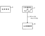
次に、図7及び図8を参照して変形例を説明する。上記実施例では、払出制御基板Hに設けられたリセットスイッチ38が5秒以上継続して押下された場合に、バックアップされている残賞球数カウンタ33aの値がクリアされた。これに対し、図7(a)〜(c)に示す変形例では、かかるリセットスイッチ38に代わるクリアスイッチ51を電源基板Dに設けて、そのクリアスイッチ51が押下された場合に、残賞球数カウンタ13c,33aの値をクリアするように構成している。
Next, a modification will be described with reference to FIGS. In the above embodiment, when the
図7(a)は、第1変形例を図示したブロック図である。第1変形例では、払出制御基板Hのみならず、主制御基板Cにおいても、残賞球数カウンタ13c,33aの値をバックアップしており、これらの値を電源基板Dに設けられたクリアスイッチ51を押下(操作)することによりクリアするものである。電源基板Dのクリアスイッチ51が押下されると、電源基板Dから主制御基板Cおよび払出制御基板Hへクリア信号52が入出力ポートを介してそれぞれ出力される。主制御基板Cおよび払出制御基板Hが、このクリア信号52を入力すると、各制御基板C,Hにおいて、それぞれ残賞球数カウンタ13c,33aの値が「0」クリアされる。
FIG. 7A is a block diagram illustrating a first modification. In the first modified example, not only the payout control board H but also the main control board C backs up the values of the remaining ball counters 13c and 33a, and these values are the clear switches provided on the power supply board D. It is cleared by pressing (operating) 51. When the
なお、この第1変形例のように、主制御基板Cにおいて残賞球数カウンタ13cの値や他の値をバックアップする場合には、主制御基板Cの処理を、図4のリセット割込処理に代えて、割込優先順位がNMI割込(ノンマスカブル割込)よりも低い他の割り込み(例えば、INT割込)や、割り込み以外のメイン処理で行うようにする。これにより、停電時におけるバックアップ処理、即ち停電発生時におけるバックアップデータの保存処理をNMI割込により行う場合、そのバックアップ処理を確実に実行することができる。後述する第2以降の変形例においても、同様である。 Note that when the value of the remaining prize ball counter 13c and other values are backed up in the main control board C as in the first modification, the process of the main control board C is performed as the reset interrupt process in FIG. Instead, it is performed in another interrupt (for example, INT interrupt) whose interrupt priority is lower than that of the NMI interrupt (non-maskable interrupt) or in main processing other than the interrupt. Thereby, when the backup process at the time of a power failure, that is, the backup data storage process at the time of the power failure occurs by NMI interruption, the backup process can be surely executed. The same applies to the second and subsequent modifications described later.
図7(b)は、第2変形例を図示したブロック図である。第2変形例でも、第1変形例と同様に、払出制御基板Hのみならず主制御基板Cにおいても、残賞球数カウンタ13c,33aの値をバックアップしており、これらの値を電源基板Dに設けられたクリアスイッチ51を押下(操作)することによりクリアするものである。電源基板Dのクリアスイッチ51が押下されると、まず、電源基板Dから主制御基板Cへクリア信号52が入出力ポートを介して出力される。主制御基板Cでは、このクリア信号52を入力すると、残賞球数カウンタ13cの値を「0」クリアすると共に、払出制御基板Hへクリアコマンド53を送信する。クリアコマンド53は、前述した実施例の賞球コマンドと同様に、入力および出力が固定的なバッファ(インバータゲート)16,37を介して、主制御基板Cから払出制御基板Hへ一方向に送信される。払出制御基板Hが、このクリアコマンド53を受信すると、バックアップしている残賞球数カウンタ33aの値を「0」クリアする。
FIG. 7B is a block diagram illustrating a second modification. In the second modified example, as in the first modified example, not only the payout control board H but also the main control board C backs up the values of the remaining ball counters 13c and 33a, and these values are stored in the power supply board. It is cleared by pressing (operating) a
図7(c)は、第3変形例を図示したブロック図である。第3変形例では、主制御基板Cの残賞球数カウンタ13cの値はバックアップせず、払出制御基板Hの残賞球数カウンタ33aの値のみをバックアップしており、その残賞球数カウンタ33aの値を電源基板Dに設けられたクリアスイッチ51を押下(操作)することによりクリアするものである。電源基板Dのクリアスイッチ51が押下されると、電源基板Dから払出制御基板Hへクリア信号52が入出力ポートを介して出力され、このクリア信号52を払出制御基板Hが入力すると、払出制御基板Hにおいて残賞球数カウンタ33aの値が「0」クリアされる。なお、バックアップデータのない主制御基板Cには、クリア信号52は出力されない。
FIG. 7C is a block diagram illustrating a third modification. In the third modified example, the value of the remaining prize ball number counter 13c of the main control board C is not backed up, and only the value of the remaining prize ball number counter 33a of the payout control board H is backed up. The value 33a is cleared by pressing (operating) the
図8(a)及び(b)に示す変形例では、クリアスイッチ51を電源基板Dに設けて、そのクリアスイッチ51が押下された場合に、残賞球数カウンタ13c,33aの値をクリアすると共に、主制御基板C、払出制御基板Hおよび他の制御基板Oをリセットして初期状態に復帰するように構成している。
In the modification shown in FIGS. 8A and 8B, the
図8(a)は、第4変形例を図示したブロック図である。第4変形例では、前記した第1変形例と同様に、払出制御基板Hのみならず、主制御基板Cにおいても残賞球数カウンタ13c,33aの値をバックアップしており、これらの値を電源基板Dに設けられたクリアスイッチ51を押下(操作)することによりクリアすると共に、主制御基板C、払出制御基板Hおよび他の制御基板Oをリセットするものである。電源基板Dのクリアスイッチ51が押下されると、電源基板Dから主制御基板C、払出制御基板H及び他の制御基板Oへクリア信号52が入出力ポートを介してそれぞれ出力される。主制御基板Cおよび払出制御基板Hが、このクリア信号52を入力すると、それぞれ残賞球数カウンタ13c,33aの値を「0」クリアすると共に、実行中のプログラムをリセットして初期状態に復帰する。また、クリア信号52を入力した他の制御基板Oは、実行中のプログラムをリセットして初期状態に復帰する。
FIG. 8A is a block diagram illustrating a fourth modification. In the fourth modified example, as in the first modified example described above, not only the payout control board H but also the main control board C backs up the values of the remaining prize ball counters 13c and 33a. It is cleared by pressing (operating) a
このように、電源基板Dのクリアスイッチ51によって、バックアップデータ13c,33aのクリアと、各制御基板C,H,Oのリセットとを行うことができるので、何らかの原因でパチンコ機Pの制御プログラムが暴走し誤動作した場合にも、クリアスイッチ51を操作するだけで、その暴走を停止することができる。制御プログラムの暴走時にはRAMの内容は破壊されるので、暴走により残賞球数カウンタ13c,33aの値も破壊されて誤った値が書き込まれている可能性がある。しかし、この第4変形例では、電源基板Dのクリアスイッチ51の押下により、各制御基板C,H,Oをリセットするだけでなく、バックアップデータ13c,33aをもクリアしているので、リセットにより各制御基板C,H,Oを初期状態に復帰した後、パチンコ機Pを正常に動作させることができる。なお、バックアップデータ13c,33aのクリアと各制御基板C,H,Oのリセットとは、その実行の順を逆にしても良い。
In this way, the
図8(b)は、第5変形例を図示したブロック図である。第5変形例では、前記した第2変形例と同様に、払出制御基板Hのみならず主制御基板Cにおいても、残賞球数カウンタ13c,33aの値をバックアップしており、これらの値を電源基板Dに設けられたクリアスイッチ51を押下(操作)することによりクリアすると共に、主制御基板C、払出制御基板Hおよび他の制御基板Oをリセットして初期状態に復帰するものである。
FIG. 8B is a block diagram illustrating a fifth modification. In the fifth modified example, as in the second modified example described above, not only the payout control board H but also the main control board C backs up the values of the remaining winning ball counters 13c and 33a. It is cleared by pressing (operating) a
電源基板Dのクリアスイッチ51が押下されると、まず、電源基板Dから主制御基板Cへクリア信号52が入出力ポートを介して出力される。主制御基板Cでは、このクリア信号52を入力すると、残賞球数カウンタ13cの値を「0」クリアすると共に、払出制御基板Hへクリアコマンド53およびリセットコマンド54を送信する。両コマンド53,54は、前述した実施例の賞球コマンドと同様に、入力および出力が固定的なバッファ(インバータゲート)16,37を介して、主制御基板Cから払出制御基板Hへ一方向に送信される。払出制御基板Hは、クリアコマンド53を受信すると、バックアップしている残賞球数カウンタ33aの値を「0」クリアし、また、リセットコマンド54を受信すると、実行中のプログラムをリセットして初期状態に復帰する。
When the
主制御基板Cは、また、他の制御基板Oをリセットさせるために、他の制御基板Oへリセットコマンド55を送信する。このリセットコマンド55も、主制御基板Cから払出制御基板Hへ一方向に送信される。他の制御基板Oは、リセットコマンド55を受信すると、実行中のプログラムをリセットして初期状態に復帰する。リセットコマンド55の送信後、主制御基板Cは、自ら実行中のプログラムをリセットして初期状態に復帰する。 The main control board C also transmits a reset command 55 to the other control board O in order to reset the other control board O. This reset command 55 is also transmitted from the main control board C to the payout control board H in one direction. When the other control board O receives the reset command 55, it resets the program being executed and returns to the initial state. After transmitting the reset command 55, the main control board C resets the program being executed by itself and returns to the initial state.
このように第5変形例においても、電源基板Dのクリアスイッチ51によって、バックアップデータ13c,33aのクリアと、各制御基板C,H,Oのリセットとを行うことができる。なお、主制御基板Cにおけるバックアップデータ13cのクリアと、各制御基板H,Oへのクリアコマンド53,リセットコマンド54,55の送信の順は上記説明に限定されるものではなく、その順を変更しても良いのである。
As described above, also in the fifth modified example, the
ここで、第1から第5変形例におけるクリアスイッチ51の押下(操作)方式について説明する。クリアスイッチ51bの誤操作によってバックアップデータを誤クリアしないように、クリアスイッチ51が次のように押下(操作)された場合に限って、電源基板Dからクリア信号52を出力するように構成している。
Here, the pressing (operation) method of the
第1の押下方式としては、クリアスイッチ51を押下した状態で電源基板Dの電源が投入(オン)された場合に限りクリア信号52を出力するものであり、逆に、第2の押下方式としては、クリアスイッチ51を押下した状態で電源基板Dの電源がオフされた場合に限りクリア信号52を出力するものである。
As the first pressing method, the clear signal 52 is output only when the power supply of the power supply board D is turned on while the
例えば、主制御基板Cや払出制御基板Hの暴走時に、クリア信号52や各コマンド53〜55を送信しても、これを正常に受信できない場合がある。しかし、電源の投入(オン)時には各制御基板C,H,Oが暴走していることはなく、また、電源のオフ時には、各制御基板C,H,Oが暴走時していても、バックアップデータ13c,33aを正常に保存するためのバックアップ処理を実行するため、強制割込であるNMI割込が発生するので、このNMI割込処理の中で、暴走時においてもクリア信号52や各コマンド53〜55を正常に受信することができる。よって、電源のオン(投入)又はオフを契機としてクリア信号52を出力することにより、各制御基板C,H,Oにクリア信号52や各コマンド53〜55を正常に受信させて、バックアップデータ13c,33aのクリア処理やリセットによる初期状態への復帰を確実に行わせることができるのである。
For example, when the main control board C and the payout control board H runaway, even if the clear signal 52 and the
また、第3の押下方式としては、クリアスイッチ51が所定時間(例えば5秒)以上継続して押下された場合に限りクリア信号52を出力するものであり、第4の押下方式としては、パーソナルコンピュータ等で頻繁に使われている所謂ダブルクリックを用いるものであり、即ち、クリアスイッチ51が所定時間以内に複数回押下された場合(例えば2秒以内に2回押下された場合)に限りクリア信号52を出力するものである。
The third pressing method outputs the clear signal 52 only when the
単にクリアスイッチ51が押下された場合にクリア信号52を出力するのではなく、第1から第4の押下方式のように所定条件下(所定の押下方式)でクリアスイッチ51が押下された場合に限り、電源基板Dから主制御基板Cまたは払出制御基板Hへクリア信号52を出力して、バックアップデータの誤クリアを防止している。なお、逆に、クリア信号52は、クリアスイッチ51を押下した場合に必ず出力されるように構成し、主制御基板C等におけるソフト制御によって、そのクリア信号52が前記第1から第4の押下方式に従って出力された場合に、各押下方式の実行と判断して、上述した各処理を実行するようにしても良い。かかる構成を採用すれば、クリア信号52の出力タイミングを、クリアスイッチ51の押下タイミングに合わせることができるので、クリア信号52の出力回路のハード構成を簡略化して、装置コストを低減することができるのである。
When the
当然のことながら前記第1から第4の押下方式は、第1から第5のいずれの変形例にも用いることができる押下方式であり、第1から第5のいずれの変形例に用いても良いものである。 As a matter of course, the first to fourth pressing methods are pressing methods that can be used in any of the first to fifth modifications, and can be used in any of the first to fifth modifications. It ’s good.
また、クリアスイッチ51は、必ずしも電源基板Dに直接に設ける必要はない。例えば、電源基板Dの上流側に電源基板Dをオンオフさせる電源スイッチユニットが設けられている場合には、その電源スイッチユニット上にクリアスイッチ51を設けるようにしても良い。即ち、主制御基板Cや払出制御基板Hへ信号を出力できる電気的に上流側の位置であれば、クリアスイッチ51を電源基板D以外の他の場所に設けるようにしても良いのである。なお、請求項1における「電源基板」に代えて、電源スイッチユニット等のように、主制御基板Cや払出制御基板Hへ信号を出力できる電気的に上流側の基板に「クリア作動手段」を設けるように構成しても良い。
Further, the
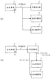
次に、図9から図13を参照して更に別の変形例を説明する。上記各実施例では1つのクリアスイッチ51を電源基板Dに設け、そのクリアスイッチ51が押下された場合に、残賞球数カウンタ13c,33aの値がクリアされた。これに対し、図9から図13に示す変形例では、クリアスイッチ51の誤押下により残賞球数カウンタ13c,33aの値が誤ってクリアされることをより確実に防止するために、2つのクリアスイッチ51a,51bを設けて、これらクリアスイッチ51a,51bが所定条件下で押下された場合に限り、残賞球数カウンタ13c,33aの値をクリアするように構成している。
Next, still another modification will be described with reference to FIGS. In each of the above embodiments, one
図9(a)〜(c)は、電源基板Dに2つのクリアスイッチ51a,51bを並列に設けた場合の例である。図9(a)は、第6変形例を示したブロック図である。第6変形例では、払出制御基板Hのみならず、主制御基板Cにおいても、残賞球数カウンタ13c,33aの値をバックアップしており、これらの値を電源基板Dに設けられたクリアスイッチ51a,51bを押下(操作)することによりクリアするものである。
FIGS. 9A to 9C show an example in which two
電源基板Dの一方のクリアスイッチ51aが押下されると、電源基板Dから主制御基板C及び払出制御基板Hへ、クリア信号52aが入出力ポート15,36を介してそれぞれ出力される。また、他方のクリアスイッチ51bが押下されると、電源基板Dから主制御基板C及び払出制御基板Hへ、別のクリア信号52bが入出力ポート15,36を介してそれぞれ出力される。主制御基板C及び払出制御基板HのMPU11,31は、両クリア信号52a,52bの入力タイミングにより、両クリアスイッチ51a,51bが所定条件で押下されたか否かを判断し、両クリアスイッチ51a,51bが所定条件で押下された場合に限り、それぞれのRAM14,33に記憶される残賞球数カウンタ13c,33aの値を「0」クリアし、且つ、実行中のプログラムをリセットして初期状態に復帰する。
When one
ここで、残賞球数カウンタ13c,33aの値を「0」クリアする場合のクリアスイッチ51a,51bの押下条件について説明する。例えば、2つのクリアスイッチ51a,51bが次の条件下で押下された場合に、残賞球数カウンタ13c,33aの値をクリアする(と共に、主制御基板Cおよび払出制御基板Hのみならず、他のすべての制御基板を初期化する)。(1)電源投入時または電源遮断時に両クリアスイッチ51a,51bが押下された場合。(2)両クリアスイッチ51a,51bが同時に押下された場合。(3)2つのクリアスイッチ51a,51bが所定時間内に所定の順番で押下された場合。なお、(1)の条件と、(2)又は(3)の条件とを組み合わせて所定条件としても良い。これらクリアスイッチ51a,51bの押下条件は、後述する変形例についても同様に用いられる。
Here, the pressing conditions of the
このように、2つのクリアスイッチ51a,51bが所定条件下で押下された場合に限り、残賞球数カウンタ13c,33aの値を「0」クリアするように構成しているので、クリアスイッチ51a,51bの誤押下による残賞球数カウンタ13c,33aの値が誤ってクリアされることをより確実に防止することができるのである。
As described above, since the values of the remaining winning ball counters 13c and 33a are cleared to “0” only when the two
図9(b)は、第7変形例を示したブロック図である。第7変形例では、第6変形例と同様に、払出制御基板Hのみならず、主制御基板Cにおいても、残賞球数カウンタ13c,33aの値をバックアップしており、これらの値を電源基板Dに設けられたクリアスイッチ51a,51bを押下(操作)することによりクリアするものである。
FIG. 9B is a block diagram showing a seventh modification. In the seventh modification, as in the sixth modification, not only the payout control board H but also the main control board C backs up the values of the remaining ball counters 13c and 33a, and these values are supplied to the power supply. Clearing is performed by pressing (operating) the
電源基板Dの一方のクリアスイッチ51aが押下されると、電源基板Dから主制御基板Cへクリア信号52aが入出力ポート15を介して出力され、また、他方のクリアスイッチ51bが押下されると、電源基板Dから主制御基板Cへ、別のクリア信号52bが入出力ポート15を介して出力される。主制御基板Cは、両クリア信号52a,52bを前述した所定条件下で入力すると、残賞球数カウンタ13cの値を「0」クリアし、実行中のプログラムをリセットして初期状態に復帰すると共に、払出制御基板Hへクリアコマンド53及びリセットコマンド55を送信する。
When one
両コマンド53,55は、前述した実施例の賞球コマンドと同様に、入力および出力が固定的なバッファ(インバータゲート)16,37を介して、主制御基板Cから払出制御基板Hへ一方向に送信される。払出制御基板Hは、クリアコマンド53を受信すると、バックアップしている残賞球数カウンタ33aの値を「0」クリアし、また、リセットコマンド55を受信すると、実行中のプログラムをリセットして初期状態に復帰する。なお、当然のことながら、主制御基板Cの残賞球数カウンタ13cの値はバックアップせず、払出制御基板Hの残賞球数カウンタ33aの値をバックアップする場合にも、この第7変形例を使用することができる。
Both commands 53 and 55 are unidirectional from the main control board C to the payout control board H via buffers (inverter gates) 16 and 37 whose inputs and outputs are fixed as in the award ball command of the above-described embodiment. Sent to. When the payout control board H receives the
図9(c)は、第8変形例を示したブロック図である。第8変形例では、第6及び第7変形例と異なり、主制御基板Cの残賞球数カウンタ13cの値はバックアップせずに、払出制御基板Hの残賞球数カウンタ33aの値をバックアップしており、この値を電源基板Dに設けられたクリアスイッチ51a,51bを押下(操作)することによりクリアするものである。
FIG. 9C is a block diagram showing an eighth modification. Unlike the sixth and seventh modifications, the eighth modification backs up the value of the remaining prize ball counter 33a of the payout control board H without backing up the value of the remaining prize ball counter 13c of the main control board C. This value is cleared by depressing (operating) the
電源基板Dの一方のクリアスイッチ51aが押下されると、電源基板Dから払出制御基板Hへクリア信号52aが入出力ポート36を介して出力され、また、他方のクリアスイッチ51bが押下されると、電源基板Dから払出制御基板Hへ、別のクリア信号52bが入出力ポート36を介して出力される。払出制御基板Hは、両クリア信号52a,52bを前述した所定条件下で入力すると、残賞球数カウンタ33aの値を「0」クリアする。なお、この場合、払出制御基板Hは、実行中のプログラムをリセットして初期状態に復帰することはしない。クリアスイッチ51a,51bの押下を認識することができない主制御基板Cでは、クリアスイッチ51a,51bの押下のタイミングで、実行中のプログラムをリセットして初期状態に復帰することができないからである。
When one
図10(a)〜(c)は、電源基板Dに2つのクリアスイッチ51a,51bを直列に設けた場合の例である。図10(a)は、第9変形例を示したブロック図である。第9変形例は、第6変形例で並列に設けられた2つのクリアスイッチ51a,51bを直列に設けたものである。この第9変形例では、払出制御基板Hのみならず、主制御基板Cにおいても、残賞球数カウンタ13c,33aの値をバックアップしており、これらの値を電源基板Dに設けられたクリアスイッチ51a,51bを押下(操作)することによりクリアするものである。
FIGS. 10A to 10C show an example in which two
電源基板Dの2つのクリアスイッチ51a,51bが同時に押下されると、電源基板Dから主制御基板C及び払出制御基板Hへ、クリア信号52が入出力ポート15,36を介してそれぞれ出力される。主制御基板C及び払出制御基板HのMPU11,31は、クリア信号52を入力することにより、両クリアスイッチ51a,51bが同時に押下されたと判断して、それぞれのRAM14,33に記憶される残賞球数カウンタ13c,33aの値を「0」クリアし、且つ、実行中のプログラムをリセットして初期状態に復帰する。なお、電源投入時または電源遮断時にのみ、両クリアスイッチ51a,51bが同時に押下された場合に限り、残賞球数カウンタ13c,33aの値を「0」クリアするように構成しても良い。
When the two
図10(b)は、第10変形例を示したブロック図である。第10変形例は、第7変形例で並列に設けられた2つのクリアスイッチ51a,51bを直列に設けたものである。この第10変形例では、第9変形例と同様に、払出制御基板Hのみならず、主制御基板Cにおいても、残賞球数カウンタ13c,33aの値をバックアップしており、これらの値を電源基板Dに設けられたクリアスイッチ51a,51bを押下(操作)することによりクリアするものである。
FIG. 10B is a block diagram showing a tenth modification. In the tenth modification, two
電源基板Dの2つのクリアスイッチ51a,51bが同時に押下されると、電源基板Dから主制御基板Cへクリア信号52が入出力ポート15を介して出力される。主制御基板Cは、クリア信号52を入力すると、残賞球数カウンタ13cの値を「0」クリアし、実行中のプログラムをリセットして初期状態に復帰すると共に、払出制御基板Hへクリアコマンド53及びリセットコマンド55を送信する。
When the two
両コマンド53,55は、前述した実施例の賞球コマンドと同様に、入力および出力が固定的なバッファ(インバータゲート)16,37を介して、主制御基板Cから払出制御基板Hへ一方向に送信される。払出制御基板Hは、クリアコマンド53を受信すると、バックアップしている残賞球数カウンタ33aの値を「0」クリアし、また、リセットコマンド55を受信すると、実行中のプログラムをリセットして初期状態に復帰する。
Both commands 53 and 55 are unidirectional from the main control board C to the payout control board H via buffers (inverter gates) 16 and 37 whose inputs and outputs are fixed as in the award ball command of the above-described embodiment. Sent to. When the payout control board H receives the
なお、当然のことながら、主制御基板Cの残賞球数カウンタ13cの値はバックアップせず、払出制御基板Hの残賞球数カウンタ33aの値をバックアップする場合にも、この第10変形例を使用することができる。また、電源投入時または電源遮断時にのみ、両クリアスイッチ51a,51bが同時に押下された場合に限り、残賞球数カウンタ13c,33aの値を「0」クリアするように構成しても良い。
Needless to say, the tenth modified example is also applicable to the case where the value of the remaining ball number counter 33a of the payout control board H is backed up without the value of the remaining ball number counter 13c of the main control board C being backed up. Can be used. Further, only when both
図10(c)は、第11変形例を示したブロック図である。第11変形例は、第8変形例で並列に設けられた2つのクリアスイッチ51a,51bを直列に設けたものである。第11変形例では、主制御基板Cの残賞球数カウンタ13cの値はバックアップせずに、払出制御基板Hの残賞球数カウンタ33aの値をバックアップしており、この値を電源基板Dに設けられたクリアスイッチ51a,51bを押下(操作)することによりクリアするものである。
FIG. 10C is a block diagram showing an eleventh modification. In the eleventh modification, two
電源基板Dの2つのクリアスイッチ51a,51bが同時に押下されると、電源基板Dから払出制御基板Hへクリア信号52が入出力ポート36を介して出力される。払出制御基板Hは、クリア信号52を入力すると、残賞球数カウンタ33aの値を「0」クリアする。なお、この場合、払出制御基板Hは、実行中のプログラムをリセットして初期状態に復帰することはしない。クリアスイッチ51a,51bの押下を認識することができない主制御基板Cでは、クリアスイッチ51a,51bの押下のタイミングで、実行中のプログラムをリセットして初期状態に復帰することができないからである。また、払出制御基板HのMPU31は、電源投入時または電源遮断時にのみ、両クリアスイッチ51a,51bが同時に押下された場合に限り、残賞球数カウンタ33aの値を「0」クリアするように構成しても良い。
When the two
図11は、第12変形例を示したブロック図である。第12変形例は、2つのクリアスイッチ51a,51bを、電源基板Dに代えて、主制御基板Cに並列に設けたものであり、払出制御基板Hのみならず、主制御基板Cにおいても、残賞球数カウンタ13c,33aの値をバックアップしており、これらの値を主制御基板Cに設けられたクリアスイッチ51a,51bを押下(操作)することによりクリアするものである。
FIG. 11 is a block diagram showing a twelfth modification. In the twelfth modification, two
まず、一方のクリアスイッチ51aが押下されると、その押下信号が入出力ポート15を介して、主制御基板CのMPU11に入力される。同様に、他方のクリアスイッチ51bが押下されると、その押下信号が入出力ポート15を介して、MPU11に入力される。両クリアスイッチ51a,51bの押下信号が、前述した所定条件下でMPU11に入力されると、MPU11は、残賞球数カウンタ13cの値を「0」クリアし、実行中のプログラムをリセットして初期状態に復帰すると共に、払出制御基板Hへクリアコマンド53及びリセットコマンド55を送信する。
First, when one of the
両コマンド53,55は、前述した実施例の賞球コマンドと同様に、入力および出力が固定的なバッファ(インバータゲート)16,37を介して、主制御基板Cから払出制御基板Hへ一方向に送信される。払出制御基板Hは、クリアコマンド53を受信すると、バックアップしている残賞球数カウンタ33aの値を「0」クリアし、また、リセットコマンド55を受信すると、実行中のプログラムをリセットして初期状態に復帰する。
Both commands 53 and 55 are unidirectional from the main control board C to the payout control board H via buffers (inverter gates) 16 and 37 whose inputs and outputs are fixed as in the award ball command of the above-described embodiment. Sent to. When the payout control board H receives the
なお、当然のことながら、主制御基板Cの残賞球数カウンタ13cの値はバックアップせず、払出制御基板Hの残賞球数カウンタ33aの値をバックアップする場合にも、この第12変形例を使用することができる。また、この第12変形例を更に変形し、2つのクリアスイッチ51a,51bを直列に設けるように構成しても良い。この場合には、2つのクリアスイッチ51a,51bが、同時に押下された場合に限り、スイッチの押下信号が入出力ポート15を介して、MPU11へ入力される。
Needless to say, the twelfth modification is also applicable to the case where the value of the remaining ball number counter 33a of the payout control board H is backed up without the value of the remaining ball number counter 13c of the main control board C being backed up. Can be used. Further, this twelfth modification may be further modified so that two
図12は、第13変形例を示したブロック図である。第13変形例は、2つのクリアスイッチ51a,51bを、払出制御基板Hに並列に設けたものである。この第13変形例では、主制御基板Cの残賞球数カウンタ13cの値はバックアップせず、払出制御基板Hの残賞球数カウンタ33aの値をバックアップしており、この値を払出制御基板Hに設けられたクリアスイッチ51a,51bを押下(操作)することによりクリアするものである。
FIG. 12 is a block diagram showing a thirteenth modification. In the thirteenth modification, two
まず、一方のクリアスイッチ51aが押下されると、その押下信号が入出力ポート36を介して、払出制御基板HのMPU31に入力される。同様に、他方のクリアスイッチ51bが押下されると、その押下信号が入出力ポート36を介して、MPU31に入力される。両クリアスイッチ51a,51bの押下信号が、前述した所定条件下でMPU31に入力されると、MPU31は、残賞球数カウンタ33aの値を「0」クリアする。なお、この場合、払出制御基板Hは、実行中のプログラムをリセットして初期状態に復帰することはしない。クリアスイッチ51a,51bの押下を認識することができない主制御基板Cでは、クリアスイッチ51a,51bの押下のタイミングで、実行中のプログラムをリセットして初期状態に復帰することができないからである。
First, when one of the
また、この第13変形例を更に変形し、2つのクリアスイッチ51a,51bを払出制御基板Hに直列に設けるように構成しても良い。この場合には、2つのクリアスイッチ51a,51bが、同時に押下された場合に限り、スイッチの押下信号が入出力ポート36を介して、MPU31へ入力される。この場合、払出制御基板HのMPU31は、電源投入時または電源遮断時にのみ、両クリアスイッチ51a,51bが同時に押下された場合に限り、残賞球数カウンタ33aの値を「0」クリアするように構成しても良い。
Further, the thirteenth modification may be further modified so that two
図13(a)〜(e)は、電源基板Dと主制御基板Cと払出制御基板Hとの3つの基板のうち2つの基板に、2つのクリアスイッチ51a,51bをそれぞれ1つずつ設けた場合の例である。
13A to 13E, two
図13(a)は、第14変形例を示したブロック図である。第14変形例は、1つのクリアスイッチ51aを電源基板Dに設け、もう1つのクリアスイッチ51bを主制御基板Cに設けたものである。この第14変形例では、主制御基板Cおよび払出制御基板Hの残賞球数カウンタ13c,33aの値をバックアップしており、2つのクリアスイッチ51a,51bが所定条件下で押下(操作)された場合に、これらの値をクリアするものである。
FIG. 13A is a block diagram showing a fourteenth modification. In the fourteenth modification, one
電源基板Dに設けられたクリアスイッチ51aが押下されると、電源基板Dから主制御基板Cへ、その押下を知らせるクリア信号52が出力される。このクリア信号52は、主制御基板Cの入出力ポート15を介して、MPU11に入力される。また、主制御基板Cに設けられたクリアスイッチ51bが押下されると、その押下信号は、入出力ポート15を介してMPU11に入力される。MPU11は、クリア信号52及び押下信号によって、両クリアスイッチ51a,51bが前述した所定条件下で押下されたと判断すると、残賞球数カウンタ13cの値を「0」クリアし、実行中のプログラムをリセットして初期状態に復帰すると共に、払出制御基板Hへクリアコマンド53及びリセットコマンド55を送信する。
When the
両コマンド53,55は、前述した実施例の賞球コマンドと同様に、入力および出力が固定的なバッファ(インバータゲート)16,37を介して、主制御基板Cから払出制御基板Hへ一方向に送信される。払出制御基板Hは、クリアコマンド53を受信すると、バックアップしている残賞球数カウンタ33aの値を「0」クリアし、また、リセットコマンド55を受信すると、実行中のプログラムをリセットして初期状態に復帰する。なお、当然のことながら、主制御基板Cの残賞球数カウンタ13cの値はバックアップせず、払出制御基板Hの残賞球数カウンタ33aの値をバックアップする場合にも、この第14変形例を使用することができる。
Both commands 53 and 55 are unidirectional from the main control board C to the payout control board H via buffers (inverter gates) 16 and 37 whose inputs and outputs are fixed as in the award ball command of the above-described embodiment. Sent to. When the payout control board H receives the
図13(b)は、第15変形例を示したブロック図である。第15変形例は、前記した第14変形例と同様に、1つのクリアスイッチ51aを電源基板Dに設け、もう1つのクリアスイッチ51bを主制御基板Cに設けたものであるが、主制御基板Cの残賞球数カウンタ13cの値はバックアップせずに、払出制御基板Hの残賞球数カウンタ33aの値をバックアップしている。2つのクリアスイッチ51a,51bが所定条件下で押下(操作)されると、払出制御基板Hの残賞球数カウンタ33aの値がクリアされる。
FIG. 13B is a block diagram showing a fifteenth modification. In the fifteenth modification, as in the fourteenth modification described above, one
電源基板Dに設けられたクリアスイッチ51aが押下されると、電源基板Dから払出制御基板Hへ、その押下を知らせるクリア信号52が出力される。このクリア信号52は、払出制御基板Hの入出力ポート36を介して、MPU31に入力される。一方、主制御基板Cに設けられたクリアスイッチ51bが押下されると、その押下信号は、入出力ポート15を介して主制御基板CのMPU11に入力され、MPU11により、主制御基板Cから払出制御基板Hへクリアコマンド53が送信される。払出制御基板HのMPU31は、クリア信号52及びクリアコマンド53を入力すると、両クリアスイッチ51a,51bが前述した所定条件下で押下されたか否かを判断し、所定条件下で押下されていれば、バックアップしている残賞球数カウンタ33aの値を「0」クリアする。
When a
なお、この場合、払出制御基板Hは、実行中のプログラムをリセットして初期状態に復帰することはしない。電源基板Dに設けられるクリアスイッチ51aの押下を認識することができない主制御基板Cでは、両クリアスイッチ51a,51bが所定条件下で押下されたか否かを認識することができないからである。
In this case, the payout control board H does not reset the program being executed and does not return to the initial state. This is because the main control board C that cannot recognize the depression of the
図13(c)は、第16変形例を示したブロック図である。第16変形例は、1つのクリアスイッチ51aを電源基板Dに設け、もう1つのクリアスイッチ51bを払出制御基板Hに設けたものであり、主制御基板Cの残賞球数カウンタ13cの値はバックアップせずに、払出制御基板Hの残賞球数カウンタ33aの値をバックアップしている。2つのクリアスイッチ51a,51bが所定条件下で押下(操作)されると、払出制御基板Hの残賞球数カウンタ33aの値がクリアされる。
FIG. 13C is a block diagram showing a sixteenth modification. In the sixteenth modification, one
電源基板Dに設けられたクリアスイッチ51aが押下されると、電源基板Dから主制御基板Cへ、その押下を知らせるクリア信号52が出力される。このクリア信号52は、主制御基板Cの入出力ポート15を介して、MPU11に入力される。MPU11は、クリア信号52を入力すると、払出制御基板Hへクリアコマンド53を送信する。
When the
一方、払出制御基板Hに設けられたクリアスイッチ51bが押下されると、その押下信号は、入出力ポート36を介して払出制御基板HのMPU31に入力される。MPU31は、かかる押下信号及びクリアコマンド53の入力タイミングにより、両クリアスイッチ51a,51bが前述した所定条件下で押下されているか否かを判断し、所定条件下で押下されていれば、バックアップしている残賞球数カウンタ33aの値を「0」クリアする。
On the other hand, when the
なお、この場合、払出制御基板Hは、実行中のプログラムをリセットして初期状態に復帰することはしない。主制御基板Cでは、両クリアスイッチ51a,51bが所定条件下で押下されたか否かを認識することができないからである。
In this case, the payout control board H does not reset the program being executed and does not return to the initial state. This is because the main control board C cannot recognize whether or not both
図13(d)は、第17変形例を示したブロック図である。第17変形例は、前記した第16変形例と同様に、1つのクリアスイッチ51aを電源基板Dに設け、もう1つのクリアスイッチ51bを払出制御基板Hに設けたものであり、主制御基板Cの残賞球数カウンタ13cの値はバックアップせずに、払出制御基板Hの残賞球数カウンタ33aの値をバックアップしている。2つのクリアスイッチ51a,51bが所定条件下で押下(操作)されると、払出制御基板Hの残賞球数カウンタ33aの値がクリアされる。
FIG. 13D is a block diagram showing a seventeenth modification. In the seventeenth modification, as in the sixteenth modification described above, one
電源基板Dに設けられたクリアスイッチ51aが押下されると、電源基板Dから払出制御基板Hへ、その押下を知らせるクリア信号52が出力される。このクリア信号52は、払出制御基板Hの入出力ポート36を介して、MPU31に入力される。また、払出制御基板Hに設けられたクリアスイッチ51bが押下されると、その押下信号は、入出力ポート36を介して払出制御基板HのMPU31に入力される。MPU31は、かかる押下信号及びクリア信号52により、両クリアスイッチ51a,51bが前述した所定条件下で押下されたか否かを判断し、所定条件下で押下されていれば、バックアップしている残賞球数カウンタ33aの値を「0」クリアする。
When a
なお、この場合、払出制御基板Hは、実行中のプログラムをリセットして初期状態に復帰することはしない。主制御基板Cでは、両クリアスイッチ51a,51bが所定条件下で押下されたか否かを認識することができないからである。
In this case, the payout control board H does not reset the program being executed and does not return to the initial state. This is because the main control board C cannot recognize whether or not both
図13(e)は、第18変形例を示したブロック図である。第18変形例は、1つのクリアスイッチ51aを主制御基板Cに設け、もう1つのクリアスイッチ51bを払出制御基板Hに設けたものであり、主制御基板Cの残賞球数カウンタ13cの値はバックアップせずに、払出制御基板Hの残賞球数カウンタ33aの値をバックアップしている。2つのクリアスイッチ51a,51bが所定条件下で押下(操作)されると、払出制御基板Hの残賞球数カウンタ33aの値がクリアされる。
FIG. 13E is a block diagram showing an eighteenth modification. In the eighteenth modified example, one
主制御基板Cに設けられたクリアスイッチ51aが押下されると、その押下信号は、入出力ポート15を介して主制御基板CのMPU11に入力され、MPU11により、主制御基板Cから払出制御基板Hへクリアコマンド53が送信される。また、払出制御基板Hに設けられたクリアスイッチ51bが押下されると、その押下信号は、入出力ポート36を介して払出制御基板HのMPU31に入力される。MPU31は、かかる押下信号及びクリアコマンド53により、両クリアスイッチ51a,51bが前述した所定条件下で押下されたか否かを判断し、所定条件下で押下されていれば、バックアップしている残賞球数カウンタ33aの値を「0」クリアする。
When the
なお、この場合、払出制御基板Hは、実行中のプログラムをリセットして初期状態に復帰することはしない。主制御基板Cでは、払出制御基板Hに設けられるクリアスイッチ51bの押下を認識することができないので、両クリアスイッチ51a,51bが所定条件下で押下されたか否かを認識することができないからである。
In this case, the payout control board H does not reset the program being executed and does not return to the initial state. Since the main control board C cannot recognize the depression of the
以上、図9から図13を参照して、2つのクリアスイッチ51a,51bが設けられた場合の変形例を説明したが、クリアスイッチ51a,51bは必ずしも2つに限られるものではなく、3以上設けるようにしても良い。例えば、図14(a)及び(b)に示すように、電源基板Dと主制御基板Cと払出制御基板Hとの3つの基板のそれぞれに、3つのクリアスイッチ51a〜51cをそれぞれ1つずつ設けるようにしても良い。図14(a)に示す例では、電源基板Dのクリアスイッチ51aが押下されると、電源基板Dから主制御基板Cへクリア信号52が出力され、一方、図14(b)に示す例では、電源基板Dのクリアスイッチ51aが押下されると、電源基板Dから払出制御基板Hへクリア信号52が出力される。また、図14(a)及び(b)のいずれも場合にも、主制御基板Cのクリアスイッチ51bの押下により、主制御基板Cから払出制御基板Hへクリアコマンド53が送信される。
As described above, the modification example in which the two
なお、当然のことながら、各基板D,C,Hのクリアスイッチ51a〜51cは、必ずしも1個である必要はなく、各基板D,C,Hのそれぞれ或いはいずれかのクリアスイッチ51a〜51cを、2以上のクリアスイッチで構成し、これらを直列又は並列に接続するようにしても良いのである。更に、上記各変形例におけるクリアスイッチ51a〜51cとしては、押しボタンスイッチ、ロック付き押しボタンスイッチ、スライドスイッチ、トグルスイッチ等を使用することができる。
As a matter of course, the number of
上記実施例において、請求項1記載の有価物体の払出残数情報としては、払出制御基板Hによって払い出される賞球数のうち未払いの賞球数が該当する。 In the above embodiment, as the payout remaining number information of the valuable object according to the first aspect, the number of unpaid prize balls among the number of prize balls paid out by the payout control board H corresponds.
以上、実施例に基づき本発明を説明したが、本発明は上記実施例に何ら限定されるものではなく、本発明の趣旨を逸脱しない範囲内で種々の改良変形が可能であることは容易に推察できるものである。 The present invention has been described based on the embodiments. However, the present invention is not limited to the above-described embodiments, and various improvements and modifications can be easily made without departing from the spirit of the present invention. It can be guessed.
例えば、上記実施例では、払出制御基板HのRAM33の内容は、バックアップ用のコンデンサ33bによって、残賞球数カウンタ33aの値に限らず、すべてバックアップされた。しかし、かかるコンデンサ33bによって、残賞球数カウンタ33aの値のみをバックアップするように構成しても良い。
For example, in the above embodiment, the contents of the
また、リセットスイッチ38が1秒以上継続して押下されることにより、払出制御基板Hで発生しているすべてのエラーを解除するのではなく、払出制御基板Hで発生しているエラーのうち、払出制御基板Hに特有のエラーのみを解除するようにしても良い。前記した通り、主制御基板Cと払出制御基板Hとの送受信は、主制御基板Cから払出制御基板Hへの一方向にのみ行われるので、払出制御基板Hのリセットスイッチ38が1秒以上押下されても、払出制御基板Hのエラーを解除することはできるが、主制御基板Cのエラーを解除することはできない。払出制御基板Hで発生するエラーの中には、払い出される賞球数が不足する賞球未検知エラーや逆に払い出される賞球数が多すぎる賞球オーバーエラー等のように、主制御基板Cと払出制御基板Hとの双方で管理しているエラーがある。かかるエラーを払出制御基板Hでのみ解除すると、主制御基板Cと払出制御基板Hとの状態に不一致を生じて、制御に支障を来してしまうからである。
Further, when the
本発明を上記実施例とは異なるタイプのパチンコ機等に実施しても良い。例えば、一度大当たりすると、それを含めて複数回(例えば2回、3回)大当たり状態が発生するまで、大当たり期待値が高められるようなパチンコ機(通称、2回権利物、3回権利物と称される)として実施しても良い。また、大当たり図柄が表示された後に、所定の領域に球を入賞させることを必要条件として特別遊技状態となるパチンコ機として実施しても良い。更に、パチンコ機以外にも、アレパチ、雀球、スロットマシン、いわゆるパチンコ機とスロットマシンとが融合した遊技機などの各種遊技機として実施するようにしても良い。 You may implement this invention in the pachinko machine etc. of a different type from the said Example. For example, once a big hit, a pachinko machine that raises the expected value of the big hit until a big hit state occurs (for example, two times or three times) including that (for example, a two-time right item, a three-time right item) May also be implemented. Moreover, after the jackpot symbol is displayed, it may be implemented as a pachinko machine that enters a special game state under the condition that a ball is awarded in a predetermined area. Further, in addition to the pachinko machine, the game machine may be implemented as various game machines such as an alepatchi, a sparrow ball, a slot machine, a game machine in which a so-called pachinko machine and a slot machine are integrated.
なお、スロットマシンは、例えばコインを投入して図柄有効ラインを決定させた状態で操作レバーを操作することにより図柄が変動され、ストップボタンを操作することにより図柄が停止されて確定される周知のものである。従って、スロットマシンの基本概念としては、「複数の識別情報からなる識別情報列を変動表示した後に識別情報を確定表示する可変表示手段を備え、始動用操作手段(例えば操作レバー)の操作に起因して識別情報の変動が開始され、停止用操作手段(例えばストップボタン)の操作に起因して、或いは、所定時間経過することにより、識別情報の変動が停止され、その停止時の確定識別情報が特定識別情報であることを必要条件として、遊技者に有利な特別遊技状態を発生させる特別遊技状態発生手段とを備えたスロットマシン」となり、この場合、遊技媒体はコイン、メダル等が代表例として挙げられる。 In the slot machine, for example, a symbol is changed by operating a control lever in a state where a symbol effective line is determined by inserting coins, and a symbol is stopped and confirmed by operating a stop button. Is. Therefore, the basic concept of the slot machine is that it is provided with variable display means for confirming and displaying the identification information after variably displaying the identification information string composed of a plurality of identification information, and resulting from the operation of the starting operation means (for example, the operation lever). Then, the change of the identification information is started, and the change of the identification information is stopped due to the operation of the operation means for stop (for example, the stop button) or after the lapse of a predetermined time, and the fixed identification information at the time of the stop Is a slot machine provided with special game state generating means for generating a special game state advantageous to the player on the condition that the specific identification information is a necessary condition. In this case, coins, medals, etc. are representative examples of game media As mentioned.
また、パチンコ機とスロットマシンとが融合した遊技機の具体例としては、複数の図柄からなる図柄列を変動表示した後に図柄を確定表示する可変表示手段を備えており、球打出用のハンドルを備えていないものが挙げられる。この場合、所定の操作(ボタン操作)に基づく所定量の球の投入の後、例えば操作レバーの操作に起因して図柄の変動が開始され、例えばストップボタンの操作に起因して、或いは、所定時間経過することにより、図柄の変動が停止され、その停止時の確定図柄がいわゆる大当たり図柄であることを必要条件として遊技者に有利な大当たり状態が発生させられ、遊技者には、下部の受皿に多量の球が払い出されるものである。 In addition, as a specific example of a gaming machine in which a pachinko machine and a slot machine are integrated, a variable display means for displaying a symbol after a symbol string composed of a plurality of symbols is displayed, and a handle for launching a ball is provided. What is not provided. In this case, after throwing a predetermined amount of spheres based on a predetermined operation (button operation), for example, the change of the symbol is started due to the operation of the operation lever, for example, due to the operation of the stop button, or With the passage of time, the fluctuation of the symbol is stopped, and a jackpot state advantageous to the player is generated on the condition that the confirmed symbol at the time of stoppage is a so-called jackpot symbol. A lot of balls are paid out.
以下に本発明の変形例を示す。請求項1記載の遊技機において、前記主制御手段は、有価物体の払出残数を記憶する主残数記憶手段と、その主残数記憶手段の内容を電源の切断後においても保持する主バックアップ手段とを備えており、前記クリア手段は、前記払出制御手段の残数記憶手段の内容のみならず、前記主制御手段の主残数記憶手段の内容をもクリアするものであることを特徴とする遊技機1。 The modification of this invention is shown below. 2. The gaming machine according to claim 1, wherein the main control means includes a main remaining number storage means for storing a payout remaining number of valuable objects, and a main backup for retaining the contents of the main remaining number storage means even after the power is turned off. And the clearing means clears not only the contents of the remaining number storage means of the payout control means but also the contents of the main remaining number storage means of the main control means. A gaming machine 1 to play.
請求項1記載の遊技機、又は、遊技機1において、前記クリア手段の2以上のスイッチ手段は並列に設けられていることを特徴とする遊技機2。 2. A gaming machine according to claim 1, wherein two or more switch means of said clearing means are provided in parallel.
請求項1記載の遊技機、又は、遊技機1において、前記クリア手段の2以上のスイッチ手段は直列に設けられていることを特徴とする遊技機3。 2. The gaming machine according to claim 1, wherein two or more switch means of the clearing means are provided in series.
請求項1記載の遊技機、又は遊技機1から3のいずれかにおいて、前記主制御手段および払出制御手段へ駆動電力を供給する電源手段を備えており、前記クリア手段の2以上のスイッチ手段は、前記電源手段、主制御手段又は払出制御手段のうち1又は2以上の手段に設けられていることを特徴とする遊技機4。なお、2以上のスイッチ手段を、電源手段、主制御手段又は払出制御手段に、それぞれ1又は2以上設けるように構成しても良い。 The gaming machine according to claim 1, or any one of the gaming machines 1 to 3, further comprising power supply means for supplying driving power to the main control means and the payout control means, wherein two or more switch means of the clearing means include The gaming machine 4 is provided in one or more of the power supply means, the main control means, or the payout control means. Two or more switch means may be provided in the power supply means, the main control means, or the payout control means, respectively.
請求項1記載の遊技機、又は遊技機1から4のいずれかにおいて、前記クリア手段は、そのクリア手段の2以上のスイッチ手段が押下された場合に、前記電源手段から前記払出制御手段(又は主制御手段)へクリア信号を出力し、そのクリア信号により前記払出制御手段(又は前記主制御手段)の残数記憶手段(又は主残数記憶手段)の内容をクリアするものであることを特徴とする遊技機5。
4. The gaming machine according to claim 1, or any one of the gaming machines 1 to 4, wherein the clearing means is configured such that when two or more switch means of the clearing means are pressed, the payout control means (or the power supply means) A clear signal is output to the main control means, and the content of the remaining number storage means (or main remaining number storage means) of the payout control means (or the main control means) is cleared by the clear signal. A
請求項1記載の遊技機、又は遊技機1から4のいずれかにおいて、前記クリア手段は、そのクリア手段の2以上のスイッチ手段が押下された場合に、(前記主制御手段の主記憶手段の内容をクリアすると共に、)前記主制御手段から前記払出制御手段へクリア信号を出力し、そのクリア信号により前記払出制御手段の残数記憶手段の内容をクリアするものであることを特徴とする遊技機6。 2. The gaming machine according to claim 1, or any one of the gaming machines 1 to 4, wherein the clearing unit is configured to (when the two or more switch units of the clearing unit are pressed (in the main storage unit of the main control unit). A game characterized by clearing the contents) and outputting a clear signal from the main control means to the payout control means, and clearing the contents of the remaining number storage means of the payout control means by the clear signal. Machine 6.
請求項1記載の遊技機、又は遊技機1から4のいずれかにおいて、前記クリア手段は、そのクリア手段の2以上のスイッチ手段が押下された場合に、前記電源手段から前記主制御手段へクリア信号を出力し、(そのクリア信号により前記主制御手段の主記憶手段の内容をクリアすると共に、)前記主制御手段から前記払出制御手段へクリアコマンドを送信させて、その払出制御手段の残数記憶手段の内容をクリアするものであることを特徴とする遊技機7。
2. The gaming machine according to claim 1, or any one of the gaming machines 1 to 4, wherein the clearing means clears from the power supply means to the main control means when two or more switch means of the clearing means are pressed. Output a signal (with the clear signal clearing the contents of the main storage means of the main control means) and send a clear command from the main control means to the payout control means, and the remaining number of the payout control means A
請求項1記載の遊技機、又は遊技機1から7のいずれかにおいて、前記クリア手段は、そのクリア手段の2以上のスイッチ手段が押下された場合に、前記残数記憶手段(又は主残数記憶手段)の内容をクリアすると共に、前記払出制御手段(又は主制御手段)をリセットして、その払出制御手段(又は主制御手段)を初期状態に復帰させるものであることを特徴とする遊技機8。なお、この場合、他の制御手段をも同時にリセットして、遊技機全体を初期状態に復帰させるようにしても良い。 4. The gaming machine according to claim 1, or any one of the gaming machines 1 to 7, wherein the clearing unit is configured to store the remaining number storage unit (or main remaining number) when two or more switch units of the clearing unit are pressed. The content of the storage means) is cleared, and the payout control means (or main control means) is reset to return the payout control means (or main control means) to the initial state. Machine 8. In this case, other control means may be reset at the same time to return the entire gaming machine to the initial state.
請求項1記載の遊技機、又は遊技機1から8のいずれかにおいて、前記クリア手段は、そのクリア手段の2以上のスイッチ手段が所定の条件下で押下された場合に作動するものであることを特徴とする遊技機9。なお、2以上のスイッチ手段が所定の条件下で押下されたか否かの判断は、主制御手段又は払出制御手段で行われる。また、所定条件としては、例えば、次に示す場合がある。(1)スイッチ手段を操作した状態で電源が投入された場合。(2)スイッチ手段を操作した状態で電源がオフされた場合。この場合には、電源のオフにより制御系の回路が動作できなくなるまでの間に記憶手段(又は主記憶手段)の内容のクリアが行われるか、或いは、電源のオフにより制御系の回路が動作できなくなるまでの間に電源オフ時にスイッチ手段が操作されたことを記憶しておき、次の電源投入時に記憶手段(又は主記憶手段)の内容をクリアするようにする。(3)スイッチ手段が所定時間内に、所定の順序で、或いは、同時に、1回又は複数回操作された場合。 2. The gaming machine according to claim 1, or any one of the gaming machines 1 to 8, wherein the clearing means operates when two or more switch means of the clearing means are pressed under a predetermined condition. A gaming machine 9 characterized by: Whether or not two or more switch means are pressed under a predetermined condition is determined by the main control means or the payout control means. Moreover, as a predetermined condition, there are the following cases, for example. (1) When the power is turned on with the switch means operated. (2) When the power is turned off while the switch means is operated. In this case, the contents of the storage means (or main storage means) are cleared until the control system circuit becomes inoperable due to the power being turned off, or the control system circuit is operated by turning off the power. The fact that the switch means has been operated when the power is turned off until the power cannot be stored is stored, and the contents of the storage means (or main storage means) are cleared when the power is turned on next time. (3) The switch means is operated once or a plurality of times within a predetermined time in a predetermined order or simultaneously.
請求項1記載の遊技機または遊技機1から9のいずれかにおいて、前記遊技機はパチンコ機であることを特徴とする遊技機10。中でも、パチンコ機の基本構成としては操作ハンドルを備え、その操作ハンドルの操作に応じて球を所定の遊技領域へ発射し、球が遊技領域内の所定の位置に配設された作動口に入賞(又は作動口を通過)することを必要条件として、表示装置において変動表示されている識別情報が所定時間後に確定停止されるものが挙げられる。また、特別遊技状態の発生時には、遊技領域内の所定の位置に配設された可変入賞装置(特定入賞口)が所定の態様で開放されて球を入賞可能とし、その入賞個数に応じた有価価値(景品球のみならず、磁気カードへ書き込まれるデータ等も含む)が付与されるものが挙げられる。 The gaming machine 10 according to any one of claims 1 to 9, wherein the gaming machine is a pachinko machine. Above all, the basic configuration of a pachinko machine is equipped with an operation handle, and in response to the operation of the operation handle, a ball is launched into a predetermined game area, and the ball is awarded to an operating port arranged at a predetermined position in the game area. As a necessary condition (or passing through the working port), the identification information variably displayed on the display device is confirmed and stopped after a predetermined time. In addition, when a special gaming state occurs, a variable winning device (specific winning opening) disposed at a predetermined position in the gaming area is opened in a predetermined manner so that a ball can be won, and a value corresponding to the number of winnings is obtained. Examples include those to which values (including data written on magnetic cards as well as premium balls) are given.
請求項1記載の遊技機または遊技機1から9のいずれかにおいて、前記遊技機はスロットマシンであることを特徴とする遊技機11。中でも、スロットマシンの基本構成としては、「複数の識別情報からなる識別情報列を変動表示した後に識別情報を確定表示する可変表示手段を備え、始動用操作手段(例えば操作レバー)の操作に起因して、或いは、所定時間経過することにより、識別情報の変動が停止され、その停止時の確定識別情報が特定識別情報であることを必要条件として、遊技者に有利な特別遊技状態を発生させる特別遊技状態発生手段とを備えた遊技機」となる。この場合、遊技媒体はコイン、メダル等が代表例として挙げられる。
10. The
請求項1記載の遊技機または遊技機1から9のいずれかにおいて、前記遊技機はパチンコ機とスロットマシンとを融合させたものであることを特徴とする遊技機12。中でも、融合させた遊技機の基本構成としては、「複数の識別情報からなる識別情報列を変動表示した後に識別情報を確定表示する可変表示手段を備え、始動用操作手段(例えば操作レバー)の操作に起因して識別情報の変動が開始され、停止用操作手段(例えばストップボタン)の操作に起因して、或いは、所定時間経過することにより、識別情報の変動が停止され、その停止時の確定識別情報が特定識別情報であることを必要条件として、遊技者に有利な特別遊技状態を発生させる特別遊技状態発生手段とを備え、遊技媒体として球を使用すると共に、前記識別情報の変動開始に際しては所定数の球を必要とし、特別遊技状態の発生に際しては多くの球が払い出されるように構成されている遊技機」となる。
10. The
13 主制御基板のRAM(記憶手段)
13c 主制御基板の残賞球数カウンタ
17 普通入賞スイッチ
21 賞球払出用モータ
22 賞球カウントスイッチ
33 払出制御基板のRAM
33a 払出制御基板の残賞球数カウンタ
33b バックアップ用コンデンサ
34 7セグメントLED
38 リセットスイッチ
51 クリアスイッチ(押下式操作スイッチ)
51a,51b,51c クリアスイッチ
52 クリア信号
52a,52b クリア信号
53 クリアコマンド(クリア時コマンド)
54,55 リセットコマンド
C 主制御基板(主制御手段)
D 電源基板
H 払出制御基板(サブ制御手段)
O 他の制御基板
P パチンコ機(遊技機)
S 賞球払出ユニット
13 RAM of main control board (storage means)
13c Number of remaining prize balls on
33a Payout control board remaining
38
51a, 51b, 51c Clear switch 52 Clear signal 52a,
54 and 55 reset command C main control board (main control means)
D Power supply board H Discharge control board (sub control means)
O the other control board P pachinko machine (game machine)
S prize ball dispensing unit
Claims (1)
前記主制御基板は、
少なくとも有価物体の払出残数情報を記憶すると共に、その記憶した払出残数情報を電源の切断後においても保持可能な記憶手段と、
その記憶手段の内容をクリアするクリア処理手段と、
そのクリア処理手段によって前記記憶手段に記憶される内容をクリアする場合に、前記サブ制御基板にクリア時コマンドを出力するコマンド出力手段と、を備え、
前記サブ制御基板は、前記クリア時コマンドを受信した場合に、そのクリア時コマンドに対応した制御を行うものであり、そのクリア時コマンドに対応した制御を行った場合に初期状態にリセットされず、
前記クリア処理手段は、前記押下式操作スイッチが押下操作された状態で、電源が所定状態に切り替えられた場合に、前記記憶手段に記憶される内容をクリアし、
前記記憶手段は、バックアップ用コンデンサによって電源の切断後においても記憶内容を保持可能であり、該保持される記憶内容は、前記払出残数情報以外の情報を含む記憶内容であることを特徴とする遊技機。 A main control board for controlling the game, a sub control board for performing predetermined control based on a command transmitted from the main control board, a power supply board for supplying driving power to the main control board and the sub control board, In a gaming machine comprising a push-type operation switch,
The main control board is
Storage means capable of storing at least the payout remaining number information of the valuable object, and holding the stored payout remaining number information even after the power is turned off;
Clear processing means for clearing the contents of the storage means;
Command output means for outputting a command at the time of clearing to the sub-control board when clearing the contents stored in the storage means by the clear processing means,
The sub-control board, when receiving the clear time command, the clear time of a row Umono control corresponding to the command is not reset to the initial state when performing control corresponding to the clear time of the command ,
The clear processing means clears the content stored in the storage means when the power source is switched to a predetermined state with the push-type operation switch being pressed.
The storage means can retain the stored contents even after the power is cut off by a backup capacitor, and the stored contents are stored contents including information other than the payout remaining number information. Gaming machine.
Priority Applications (1)
| Application Number | Priority Date | Filing Date | Title |
|---|---|---|---|
| JP2010238220A JP5594058B2 (en) | 1999-12-14 | 2010-10-25 | Game machine |
Applications Claiming Priority (5)
| Application Number | Priority Date | Filing Date | Title |
|---|---|---|---|
| JP35397599 | 1999-12-14 | ||
| JP1999353975 | 1999-12-14 | ||
| JP35553799 | 1999-12-15 | ||
| JP1999355537 | 1999-12-15 | ||
| JP2010238220A JP5594058B2 (en) | 1999-12-14 | 2010-10-25 | Game machine |
Related Parent Applications (1)
| Application Number | Title | Priority Date | Filing Date |
|---|---|---|---|
| JP2000157631A Division JP4686815B2 (en) | 1999-12-14 | 2000-05-29 | Game machine |
Related Child Applications (1)
| Application Number | Title | Priority Date | Filing Date |
|---|---|---|---|
| JP2013004461A Division JP5729396B2 (en) | 1999-12-14 | 2013-01-15 | Game machine |
Publications (2)
| Publication Number | Publication Date |
|---|---|
| JP2011016004A JP2011016004A (en) | 2011-01-27 |
| JP5594058B2 true JP5594058B2 (en) | 2014-09-24 |
Family
ID=42573443
Family Applications (7)
| Application Number | Title | Priority Date | Filing Date |
|---|---|---|---|
| JP2010091806A Expired - Lifetime JP4605309B2 (en) | 1999-12-14 | 2010-04-12 | Game machine |
| JP2010091805A Expired - Lifetime JP4605308B2 (en) | 1999-12-14 | 2010-04-12 | Game machine |
| JP2010169347A Pending JP2010234126A (en) | 1999-12-14 | 2010-07-28 | Controller for game machine |
| JP2010169348A Expired - Lifetime JP5593922B2 (en) | 1999-12-14 | 2010-07-28 | Game machine |
| JP2010238220A Expired - Lifetime JP5594058B2 (en) | 1999-12-14 | 2010-10-25 | Game machine |
| JP2013004461A Expired - Lifetime JP5729396B2 (en) | 1999-12-14 | 2013-01-15 | Game machine |
| JP2013004463A Expired - Fee Related JP5729397B2 (en) | 1999-12-14 | 2013-01-15 | Game machine |
Family Applications Before (4)
| Application Number | Title | Priority Date | Filing Date |
|---|---|---|---|
| JP2010091806A Expired - Lifetime JP4605309B2 (en) | 1999-12-14 | 2010-04-12 | Game machine |
| JP2010091805A Expired - Lifetime JP4605308B2 (en) | 1999-12-14 | 2010-04-12 | Game machine |
| JP2010169347A Pending JP2010234126A (en) | 1999-12-14 | 2010-07-28 | Controller for game machine |
| JP2010169348A Expired - Lifetime JP5593922B2 (en) | 1999-12-14 | 2010-07-28 | Game machine |
Family Applications After (2)
| Application Number | Title | Priority Date | Filing Date |
|---|---|---|---|
| JP2013004461A Expired - Lifetime JP5729396B2 (en) | 1999-12-14 | 2013-01-15 | Game machine |
| JP2013004463A Expired - Fee Related JP5729397B2 (en) | 1999-12-14 | 2013-01-15 | Game machine |
Country Status (1)
| Country | Link |
|---|---|
| JP (7) | JP4605309B2 (en) |
Families Citing this family (3)
| Publication number | Priority date | Publication date | Assignee | Title |
|---|---|---|---|---|
| JP4605309B2 (en) * | 1999-12-14 | 2011-01-05 | 株式会社三洋物産 | Game machine |
| JP5220815B2 (en) * | 2010-08-18 | 2013-06-26 | 株式会社藤商事 | Game machine |
| JP6688862B2 (en) * | 2018-11-21 | 2020-04-28 | 株式会社ニューギン | Amusement machine |
Family Cites Families (14)
| Publication number | Priority date | Publication date | Assignee | Title |
|---|---|---|---|---|
| JP3003866B2 (en) * | 1990-02-23 | 2000-01-31 | 株式会社ソフィア | Gaming machine |
| JP2733199B2 (en) * | 1994-08-22 | 1998-03-30 | 株式会社ソフィア | Amusement machine variable display device |
| JP2821425B2 (en) * | 1996-04-24 | 1998-11-05 | 株式会社三共 | Ball game machine |
| JPH11290536A (en) * | 1998-04-09 | 1999-10-26 | Taiyo Elec Co Ltd | Pinball game machine |
| JP4266246B2 (en) * | 1998-08-12 | 2009-05-20 | 株式会社三共 | Game machine |
| JP3461310B2 (en) * | 1998-11-09 | 2003-10-27 | タイヨーエレック株式会社 | Ball game machine |
| JP3978521B2 (en) * | 1999-05-25 | 2007-09-19 | タイヨーエレック株式会社 | Game machine |
| JP3747252B2 (en) * | 1999-12-01 | 2006-02-22 | 株式会社高尾 | Game machine |
| JP3462820B2 (en) * | 1999-12-14 | 2003-11-05 | 株式会社三共 | Game machine |
| JP4605309B2 (en) * | 1999-12-14 | 2011-01-05 | 株式会社三洋物産 | Game machine |
| JP4686815B2 (en) * | 1999-12-14 | 2011-05-25 | 株式会社三洋物産 | Game machine |
| JP4297466B2 (en) * | 2000-02-25 | 2009-07-15 | 株式会社ソフィア | Game machine |
| JP2001252402A (en) * | 2000-03-13 | 2001-09-18 | Heiwa Corp | Game control power system device |
| JP3640593B2 (en) * | 2000-04-06 | 2005-04-20 | 株式会社平和 | Power supply device for gaming machine |
-
2010
- 2010-04-12 JP JP2010091806A patent/JP4605309B2/en not_active Expired - Lifetime
- 2010-04-12 JP JP2010091805A patent/JP4605308B2/en not_active Expired - Lifetime
- 2010-07-28 JP JP2010169347A patent/JP2010234126A/en active Pending
- 2010-07-28 JP JP2010169348A patent/JP5593922B2/en not_active Expired - Lifetime
- 2010-10-25 JP JP2010238220A patent/JP5594058B2/en not_active Expired - Lifetime
-
2013
- 2013-01-15 JP JP2013004461A patent/JP5729396B2/en not_active Expired - Lifetime
- 2013-01-15 JP JP2013004463A patent/JP5729397B2/en not_active Expired - Fee Related
Also Published As
| Publication number | Publication date |
|---|---|
| JP5593922B2 (en) | 2014-09-24 |
| JP4605309B2 (en) | 2011-01-05 |
| JP2013063339A (en) | 2013-04-11 |
| JP2010155128A (en) | 2010-07-15 |
| JP4605308B2 (en) | 2011-01-05 |
| JP2010155129A (en) | 2010-07-15 |
| JP2013063340A (en) | 2013-04-11 |
| JP2011016004A (en) | 2011-01-27 |
| JP2010234126A (en) | 2010-10-21 |
| JP5729396B2 (en) | 2015-06-03 |
| JP2010264289A (en) | 2010-11-25 |
| JP5729397B2 (en) | 2015-06-03 |
Similar Documents
| Publication | Publication Date | Title |
|---|---|---|
| JP4686815B2 (en) | Game machine | |
| JP4556272B2 (en) | Game machine | |
| JP4706114B2 (en) | Game machine | |
| JP5729396B2 (en) | Game machine | |
| JP5083385B2 (en) | Game machine | |
| JP4259012B2 (en) | Game machine | |
| JP5263278B2 (en) | Game machine | |
| JP4797286B2 (en) | Game machine | |
| JP4023322B2 (en) | Game machine | |
| JP5652521B2 (en) | Game machine | |
| JP2007301406A (en) | Game machine | |
| JP5163700B2 (en) | Game machine | |
| JP5290246B2 (en) | Bullet ball machine | |
| JP2001232007A (en) | Controller for game machine | |
| JP2003205158A (en) | Game machine | |
| JP4576663B2 (en) | Game machine | |
| JP2016137331A (en) | Game machine | |
| JP4320685B2 (en) | Game machine | |
| JP4379514B2 (en) | Game machine | |
| JP2001321496A5 (en) | ||
| JP5637179B2 (en) | Game machine | |
| JP5585568B2 (en) | Game machine | |
| JP4295456B2 (en) | Game machine | |
| JP2003305267A (en) | Game machine | |
| JP2013031716A (en) | Game machine |
Legal Events
| Date | Code | Title | Description |
|---|---|---|---|
| A621 | Written request for application examination |
Free format text: JAPANESE INTERMEDIATE CODE: A621 Effective date: 20101122 |
|
| A131 | Notification of reasons for refusal |
Free format text: JAPANESE INTERMEDIATE CODE: A131 Effective date: 20121113 |
|
| A521 | Written amendment |
Free format text: JAPANESE INTERMEDIATE CODE: A523 Effective date: 20130115 |
|
| A131 | Notification of reasons for refusal |
Free format text: JAPANESE INTERMEDIATE CODE: A132 Effective date: 20131008 |
|
| A521 | Written amendment |
Free format text: JAPANESE INTERMEDIATE CODE: A523 Effective date: 20131107 |
|
| TRDD | Decision of grant or rejection written | ||
| A01 | Written decision to grant a patent or to grant a registration (utility model) |
Free format text: JAPANESE INTERMEDIATE CODE: A01 Effective date: 20140708 |
|
| A61 | First payment of annual fees (during grant procedure) |
Free format text: JAPANESE INTERMEDIATE CODE: A61 Effective date: 20140721 |
|
| R150 | Certificate of patent or registration of utility model |
Ref document number: 5594058 Country of ref document: JP Free format text: JAPANESE INTERMEDIATE CODE: R150 |
|
| R250 | Receipt of annual fees |
Free format text: JAPANESE INTERMEDIATE CODE: R250 |
|
| R250 | Receipt of annual fees |
Free format text: JAPANESE INTERMEDIATE CODE: R250 |
|
| R250 | Receipt of annual fees |
Free format text: JAPANESE INTERMEDIATE CODE: R250 |
|
| EXPY | Cancellation because of completion of term |