JP5592760B2 - Fuel cell power generation system - Google Patents
Fuel cell power generation system Download PDFInfo
- Publication number
- JP5592760B2 JP5592760B2 JP2010252182A JP2010252182A JP5592760B2 JP 5592760 B2 JP5592760 B2 JP 5592760B2 JP 2010252182 A JP2010252182 A JP 2010252182A JP 2010252182 A JP2010252182 A JP 2010252182A JP 5592760 B2 JP5592760 B2 JP 5592760B2
- Authority
- JP
- Japan
- Prior art keywords
- carbon monoxide
- reformer
- fuel cell
- fuel
- temperature
- Prior art date
- Legal status (The legal status is an assumption and is not a legal conclusion. Google has not performed a legal analysis and makes no representation as to the accuracy of the status listed.)
- Active
Links
Images


Classifications
-
- Y—GENERAL TAGGING OF NEW TECHNOLOGICAL DEVELOPMENTS; GENERAL TAGGING OF CROSS-SECTIONAL TECHNOLOGIES SPANNING OVER SEVERAL SECTIONS OF THE IPC; TECHNICAL SUBJECTS COVERED BY FORMER USPC CROSS-REFERENCE ART COLLECTIONS [XRACs] AND DIGESTS
- Y02—TECHNOLOGIES OR APPLICATIONS FOR MITIGATION OR ADAPTATION AGAINST CLIMATE CHANGE
- Y02E—REDUCTION OF GREENHOUSE GAS [GHG] EMISSIONS, RELATED TO ENERGY GENERATION, TRANSMISSION OR DISTRIBUTION
- Y02E60/00—Enabling technologies; Technologies with a potential or indirect contribution to GHG emissions mitigation
- Y02E60/30—Hydrogen technology
- Y02E60/50—Fuel cells
-
- Y—GENERAL TAGGING OF NEW TECHNOLOGICAL DEVELOPMENTS; GENERAL TAGGING OF CROSS-SECTIONAL TECHNOLOGIES SPANNING OVER SEVERAL SECTIONS OF THE IPC; TECHNICAL SUBJECTS COVERED BY FORMER USPC CROSS-REFERENCE ART COLLECTIONS [XRACs] AND DIGESTS
- Y02—TECHNOLOGIES OR APPLICATIONS FOR MITIGATION OR ADAPTATION AGAINST CLIMATE CHANGE
- Y02P—CLIMATE CHANGE MITIGATION TECHNOLOGIES IN THE PRODUCTION OR PROCESSING OF GOODS
- Y02P20/00—Technologies relating to chemical industry
- Y02P20/50—Improvements relating to the production of bulk chemicals
- Y02P20/52—Improvements relating to the production of bulk chemicals using catalysts, e.g. selective catalysts
Description
本発明は、原燃料を改質して水素を主成分とするガスを生成する燃料改質装置と、燃料改質装置で生成された水素を主成分とするガスを用いて発電を行う燃料電池装置と、各装置の運転を制御する制御装置とを備える燃料電池発電システムに関する。 The present invention relates to a fuel reformer that reforms raw fuel to generate a gas mainly composed of hydrogen, and a fuel cell that generates power using a gas mainly composed of hydrogen generated by the fuel reformer. The present invention relates to a fuel cell power generation system including a device and a control device that controls the operation of each device.
燃料電池装置に供給する水素を主成分とするガスを生成するための装置として、燃料改質装置がある。燃料改質装置は、原燃料を改質して水素を主成分とし一酸化炭素を含む改質ガスを生成する改質器を有する。加えて、燃料改質装置は、改質ガス中に含まれる一酸化炭素を除去するための変成器を有する。変成器は、一酸化炭素と水とを反応させて、一酸化炭素を二酸化炭素に変成させる。このとき、変成器が有する一酸化炭素変成触媒が劣化していると(即ち、変成処理能力が低下していると)、変成器から排出される変成処理済ガスに含まれる一酸化炭素の量が増加し、最終的には、燃料電池へ到達する一酸化炭素の量も増加する。その結果、一酸化炭素による燃料電池の電極触媒の被毒の影響が大きくなり、燃料電池の発電電圧が低下するという問題が発生する。 There is a fuel reforming device as a device for generating a gas containing hydrogen as a main component to be supplied to the fuel cell device. The fuel reformer includes a reformer that reforms a raw fuel to generate a reformed gas containing hydrogen monoxide as a main component and carbon monoxide. In addition, the fuel reformer has a transformer for removing carbon monoxide contained in the reformed gas. The transformer converts carbon monoxide into carbon dioxide by reacting carbon monoxide with water. At this time, if the carbon monoxide shift catalyst of the shift converter is deteriorated (that is, if the shift processing capacity is lowered), the amount of carbon monoxide contained in the shift processed gas discharged from the shift converter And eventually the amount of carbon monoxide reaching the fuel cell also increases. As a result, the influence of poisoning of the electrode catalyst of the fuel cell due to carbon monoxide is increased, which causes a problem that the generated voltage of the fuel cell is lowered.
変成器における一酸化炭素変成触媒の劣化に着目した先行技術として特許文献1に記載した発明がある。特許文献1には、触媒温度が上昇しすぎると触媒の劣化が起こるという問題が記載されている。その問題を解決するために、特許文献1に記載の発明では、変成器に流入するガスを変成器の入口に設けた熱交換器で冷却することで一酸化炭素変成触媒の温度を330℃以下に制御することにより、触媒の劣化を抑制している。具体的には、変成器は、その変成器の入口のガス温度を制御するための熱交換器を特別に有する。熱交換器は、冷却水等の冷却媒体を流す冷却管、冷却板等がガスの流路に設けられた構造の装置である。この熱交換器により、変成器に収容されている一酸化炭素変成触媒の触媒層の入口のガスが冷却される。 There exists invention described in patent document 1 as prior art which paid its attention to deterioration of the carbon monoxide conversion catalyst in a converter. Patent Document 1 describes a problem that catalyst deterioration occurs when the catalyst temperature rises too much. In order to solve the problem, in the invention described in Patent Document 1, the temperature of the carbon monoxide shift catalyst is reduced to 330 ° C. or lower by cooling the gas flowing into the shift converter with a heat exchanger provided at the inlet of the shift converter. By controlling this, deterioration of the catalyst is suppressed. Specifically, the transformer specifically has a heat exchanger for controlling the gas temperature at the inlet of the transformer. The heat exchanger is an apparatus having a structure in which a cooling pipe, a cooling plate, and the like for flowing a cooling medium such as cooling water are provided in a gas flow path. By this heat exchanger, the gas at the inlet of the catalyst layer of the carbon monoxide shift catalyst accommodated in the shift converter is cooled.
特許文献1に記載の発明は、一酸化炭素変成触媒の温度制御のために、上述した特別な熱交換器が必要になる。その結果、燃料改質装置の装置コストが高くなり、且つ、装置が大きくなるという問題がある。
また、特許文献1に記載の発明は、そのような熱交換器を常時作動させて、一酸化炭素変成触媒の温度を330℃以下に制御することで、触媒の劣化を抑制しようとする技術である。つまり、一酸化炭素変成触媒が劣化しているか否かに関わらず上記熱交換器を常時作動させなければならないため、燃料改質装置が例えば10年以上運転されるとすると、熱交換器の作動のために多大なエネルギが消費されることになる。
The invention described in Patent Document 1 requires the special heat exchanger described above for temperature control of the carbon monoxide conversion catalyst. As a result, there is a problem that the device cost of the fuel reformer increases and the device becomes large.
In addition, the invention described in Patent Document 1 is a technique for suppressing deterioration of the catalyst by constantly operating such a heat exchanger and controlling the temperature of the carbon monoxide conversion catalyst to 330 ° C. or lower. is there. In other words, the heat exchanger must be constantly operated regardless of whether or not the carbon monoxide conversion catalyst is deteriorated. Therefore, if the fuel reformer is operated for, for example, 10 years or more, the heat exchanger is activated. Therefore, a great deal of energy is consumed.
本発明は、上記の課題に鑑みてなされたものであり、その目的は、活性の高い状態で一酸化炭素変成触媒を使用でき、且つ、消費エネルギが小さい燃料電池発電システムを提供する点にある。 The present invention has been made in view of the above problems, and an object of the present invention is to provide a fuel cell power generation system that can use a carbon monoxide conversion catalyst in a highly active state and that consumes less energy. .
上記目的を達成するための本発明に係る燃料電池発電システムの特徴構成は、原燃料を改質して水素を主成分とするガスを生成する燃料改質装置と、前記燃料改質装置で生成された水素を主成分とするガスを用いて発電を行う燃料電池装置と、前記各装置の運転を制御する制御装置とを備える燃料電池発電システムであって、
前記燃料改質装置は、原燃料を改質して水素を主成分とし一酸化炭素を含む改質ガスを生成する改質器と、前記改質ガスに含まれる一酸化炭素を二酸化炭素に変成する一酸化炭素変成触媒を有する変成器と、前記一酸化炭素変成触媒の温度を検出する温度検出手段と、前記一酸化炭素変成触媒を加熱可能な加熱手段とを有し、
前記制御装置は、前記一酸化炭素変成触媒が劣化発生条件を満たした状態にあり且つ前記温度検出手段による検出温度が基準温度未満である状態において、前記改質器での前記改質ガスの生成量を増加変化させている途中では、前記加熱手段の動作を変化させて前記一酸化炭素変成触媒の温度を前記基準温度以上に上昇させ、前記改質器での前記改質ガスの生成量を増加変化させないときは、前記加熱手段の動作を変化させることによって前記一酸化炭素変成触媒の温度を前記基準温度以上に上昇させることは行わない点にある。
本特徴構成において、加熱手段の動作を変化させるということは、非動作状態にある加熱手段を動作状態に切り替えること、及び、既に動作状態にある加熱手段の動作状態を変更すること(例えば、加熱量が小さい動作状態から加熱量が大きい動作状態に変化させること)の両方の概念を含む。このように、加熱手段の動作を変化させることで、触媒の活性が高い側で一酸化炭素変成触媒を使用できる。
In order to achieve the above object, the fuel cell power generation system according to the present invention is characterized by a fuel reformer that reforms raw fuel to generate a gas mainly composed of hydrogen, and a fuel reformer that generates the fuel reformer. A fuel cell power generation system comprising a fuel cell device that generates power using a gas mainly composed of hydrogen, and a control device that controls the operation of each of the devices,
The fuel reformer reforms a raw fuel to generate a reformed gas mainly containing hydrogen and containing carbon monoxide, and converts the carbon monoxide contained in the reformed gas into carbon dioxide. A converter having a carbon monoxide conversion catalyst, temperature detecting means for detecting the temperature of the carbon monoxide conversion catalyst, and heating means capable of heating the carbon monoxide conversion catalyst,
The control device generates the reformed gas in the reformer in a state where the carbon monoxide conversion catalyst satisfies a deterioration occurrence condition and a temperature detected by the temperature detecting means is lower than a reference temperature. the way that the amount is increased changes in operation to change the said heating means to raise the temperature of the carbon monoxide shift catalyst than the reference temperature, the generation amount of the reformed gas in the reformer When the increase is not changed, the temperature of the carbon monoxide shift catalyst is not raised above the reference temperature by changing the operation of the heating means .
In this feature configuration, changing the operation of the heating unit means switching the heating unit in the non-operating state to the operating state and changing the operating state of the heating unit already in the operating state (for example, heating It includes both concepts of changing from an operating state with a small amount to an operating state with a large amount of heating. Thus, by changing the operation of the heating means, the carbon monoxide conversion catalyst can be used on the side where the activity of the catalyst is high.
一酸化炭素変成触媒が劣化して活性が低い状態になると、触媒温度が同一であれば一酸化炭素の変成処理量が減少する。更に、過度に触媒の劣化が進行すると、変成処理反応が促進されず触媒温度が低くなる。但し、一酸化炭素変成触媒が所定の劣化発生条件を満たした状態(即ち、変成器における一酸化炭素のスリップ量が所定量以上である状態)にあり且つ一酸化炭素変成触媒の温度を検出する温度検出手段による検出温度が基準温度未満である状態であれば、一酸化炭素変成触媒が劣化しているという確定判断を下すことができる。尚、一酸化炭素変成触媒が劣化しているという確定判断を下したとしても、一酸化炭素変成触媒は一酸化炭素を変成処理する性能を完全に失った訳ではないため、変成処理するべきガス量が少なければ、そのガス中に存在する一酸化炭素の変成処理を行える。
しかし、電力負荷装置の電力需要が増大するなどの理由により、燃料電池の発電出力を上昇させる必要が生じたとき(即ち、改質ガスの生成量を増加させる必要が生じたとき)、変成器において変成処理するべきガス量が増加する。従って、変成器の一酸化炭素変成触媒が劣化して活性が低い場合、それまでの触媒温度を維持した状態では変成処理するべきガス量の増加に対応できず、多くの一酸化炭素が変成処理されずに変成器をスリップすることになる。
When the carbon monoxide conversion catalyst deteriorates and becomes in a low activity state, the conversion treatment amount of carbon monoxide decreases if the catalyst temperature is the same. Furthermore, if the catalyst is excessively deteriorated, the shift treatment reaction is not promoted and the catalyst temperature is lowered. However, the temperature of the carbon monoxide conversion catalyst is detected when the carbon monoxide conversion catalyst satisfies the predetermined deterioration occurrence condition (that is, the carbon monoxide slip amount in the converter is equal to or greater than the predetermined amount). If the temperature detected by the temperature detection means is lower than the reference temperature, it can be determined that the carbon monoxide shift catalyst has deteriorated. Even if a definitive judgment is made that the carbon monoxide conversion catalyst has deteriorated, the carbon monoxide conversion catalyst has not completely lost the ability to convert carbon monoxide, so the gas to be converted If the amount is small, the transformation treatment of carbon monoxide present in the gas can be performed.
However, when it becomes necessary to increase the power generation output of the fuel cell due to an increase in the power demand of the power load device (that is, when it is necessary to increase the amount of reformed gas generated), the transformer The amount of gas to be transformed is increased in Therefore, when the carbon monoxide conversion catalyst of the converter is deteriorated and the activity is low, it is not possible to cope with an increase in the amount of gas to be converted while maintaining the catalyst temperature up to that time, and a large amount of carbon monoxide is converted. Instead, the transformer will slip.
ところが本特徴構成では、制御装置は、一酸化炭素変成触媒が劣化発生条件を満たした状態にあり且つ温度検出手段による検出温度が基準温度未満である状態において、改質器での改質ガスの生成量を増加変化させている途中では、加熱手段の動作を変化させて一酸化炭素変成触媒の温度を基準温度以上に上昇させ、改質器での改質ガスの生成量を増加変化させないときは、加熱手段の動作を変化させることによって一酸化炭素変成触媒の温度を基準温度以上に上昇させることは行わない。つまり、制御装置は、一酸化炭素変成触媒の温度を上昇させることで、一酸化炭素変成触媒の活性を高めることができる。従って、触媒活性を高めることで、変成処理可能なガス量が増加するので、変成器から排出される変成処理済ガスに含まれる一酸化炭素の量、即ち、燃料電池へ供給される一酸化炭素の量を相対的に少なくできる。更に、本特徴構成では、制御装置が一酸化炭素変成触媒の活性を高めるのは、改質器での改質ガスの生成量を増加させるときであるので、他のタイミング(改質器での改質ガスの生成量を増加変化させないとき)では一酸化炭素変成触媒の活性を現状のままで保っていればよい。従って、燃料改質装置の運転に要するエネルギが必要以上に増大することを避けることができる。
従って、活性の高い状態で一酸化炭素変成触媒を使用でき、且つ、消費エネルギが小さい燃料電池発電システムを提供できる。
However, in the present characteristic configuration, the control device is in a state where the carbon monoxide conversion catalyst satisfies the deterioration occurrence condition and the temperature detected by the temperature detecting means is lower than the reference temperature, and the reforming gas of the reformer is reduced. When the production amount is being increased and changed , the operation of the heating means is changed to raise the temperature of the carbon monoxide conversion catalyst to a reference temperature or higher, and the amount of reformed gas produced in the reformer is not increased. Does not raise the temperature of the carbon monoxide shift catalyst above the reference temperature by changing the operation of the heating means. That is, the control device can increase the activity of the carbon monoxide conversion catalyst by increasing the temperature of the carbon monoxide conversion catalyst. Therefore, since the amount of gas that can be subjected to shift treatment increases by increasing the catalytic activity, the amount of carbon monoxide contained in the shift-processed gas discharged from the shift converter, that is, carbon monoxide supplied to the fuel cell. Can be relatively reduced. Furthermore, in this characteristic configuration, the control device increases the activity of the carbon monoxide conversion catalyst when increasing the amount of reformed gas generated in the reformer . When the amount of reformed gas produced is not increased and changed) , the activity of the carbon monoxide shift catalyst may be maintained as it is. Therefore, it is possible to avoid an excessive increase in energy required for operation of the fuel reformer.
Therefore, it is possible to provide a fuel cell power generation system that can use the carbon monoxide shift catalyst in a highly active state and that consumes less energy.
本発明に係る燃料電池発電システムの別の特徴構成は、前記制御装置は、前記改質器への原燃料の供給量に対する前記燃料電池装置の出力電圧が基準電圧未満であるとき、又は、前記燃料電池装置の出力電圧に対する前記改質器への原燃料の供給量が基準供給量以上であるとき、又は、前記燃料改質装置の積算運転時間が基準積算時間以上であるとき、前記一酸化炭素変成触媒が前記劣化発生条件を満たした状態にあると判断する点にある。 Another characteristic configuration of the fuel cell power generation system according to the present invention is that the control device is configured such that the output voltage of the fuel cell device with respect to the amount of raw fuel supplied to the reformer is less than a reference voltage, or When the supply amount of raw fuel to the reformer with respect to the output voltage of the fuel cell device is equal to or greater than a reference supply amount, or when the accumulated operation time of the fuel reformer is equal to or greater than a reference accumulated time, the monoxide The carbon shift catalyst is determined to be in a state satisfying the deterioration occurrence condition.
一酸化炭素変成触媒が劣化してその変成処理能力が低下すると、改質器への原燃料の供給量に変化がなくても、変成器から排出される変成処理済ガスに含まれる一酸化炭素の量が相対的に増加するため、燃料電池の発電電圧が低下することがある。そこで、制御装置は、改質器への原燃料の供給量に対する燃料電池装置の出力電圧が基準電圧未満である場合、一酸化炭素変成触媒が劣化発生条件を満たしていると判断できる。
或いは、一酸化炭素変成触媒が劣化してその変成処理能力が低下すると、変成器から排出される変成処理済ガスに含まれる一酸化炭素の量が相対的に増加するため、燃料電池から同じ発電電圧を得るのに必要とする改質器への原燃料の供給量が増加することがある。そこで、制御装置は、燃料電池装置の出力電圧に対する改質器への原燃料の供給量が基準供給量以上である場合、一酸化炭素変成触媒が劣化発生条件を満たしていると判断できる。
また或いは、燃料改質装置の積算運転時間が基準積算時間以上になると、一酸化炭素変成触媒が経年劣化していると見なしてもよい。そこで、制御装置は、燃料改質装置の積算運転時間が基準積算時間以上になると、一酸化炭素変成触媒が劣化発生条件を満たしていると判断できる。
When the carbon monoxide shift catalyst deteriorates and its shift processing capacity decreases, the carbon monoxide contained in the shift processed gas discharged from the shift converter, even if there is no change in the amount of raw fuel supplied to the reformer Since the amount of the battery increases relatively, the power generation voltage of the fuel cell may decrease. Therefore, the control device can determine that the carbon monoxide conversion catalyst satisfies the deterioration generation condition when the output voltage of the fuel cell device with respect to the amount of raw fuel supplied to the reformer is less than the reference voltage.
Alternatively, when the carbon monoxide shift catalyst deteriorates and its shift processing capacity decreases, the amount of carbon monoxide contained in the shift processed gas discharged from the shifter relatively increases, so the same power generation from the fuel cell. The amount of raw fuel supplied to the reformer that is necessary to obtain the voltage may increase. Therefore, the control device can determine that the carbon monoxide shift catalyst satisfies the deterioration occurrence condition when the supply amount of the raw fuel to the reformer with respect to the output voltage of the fuel cell device is equal to or greater than the reference supply amount.
Alternatively, when the accumulated operation time of the fuel reformer becomes equal to or longer than the reference accumulated time, the carbon monoxide conversion catalyst may be considered to have deteriorated over time. Therefore, the control device can determine that the carbon monoxide shift catalyst satisfies the deterioration occurrence condition when the accumulated operation time of the fuel reformer becomes equal to or longer than the reference accumulated time.
本発明に係る燃料電池発電システムの更に別の特徴構成は、前記加熱手段は、電気ヒータである点にある。 Yet another characteristic configuration of the fuel cell power generation system according to the present invention is that the heating means is an electric heater.
上記特徴構成によれば、制御装置は、電気ヒータへの通電量を調節することで、加熱手段の発熱量、即ち、加熱手段から一酸化炭素変成触媒へ与えられる熱量を制御できる。 According to the above characteristic configuration, the control device can control the amount of heat generated by the heating unit, that is, the amount of heat given from the heating unit to the carbon monoxide shift catalyst by adjusting the amount of current supplied to the electric heater.
本発明に係る燃料電池発電システムの更に別の特徴構成は、前記燃料改質装置は、可燃性ガスを燃焼して得られる燃焼熱によって前記改質器を加熱する燃焼器を有し、
前記燃焼器は、前記燃焼熱によって前記一酸化炭素変成触媒を加熱可能な前記加熱手段として機能する点にある。
Still another characteristic configuration of the fuel cell power generation system according to the present invention is such that the fuel reformer includes a combustor that heats the reformer with combustion heat obtained by burning a combustible gas,
The combustor functions as the heating means capable of heating the carbon monoxide shift catalyst with the combustion heat.
燃焼器は、可燃性ガスを燃焼して得られる燃焼熱によって改質器を加熱する装置である。また、燃焼器で加熱される改質器から排出される改質ガスは変成器に流入することを考慮すると、燃焼器で発生される熱は改質ガスを介して変成器にも伝えられていると言える。加えて、燃料改質装置の内部で燃焼器と変成器とが例えば断熱材などを間に挟みながらも互いに近接して設けられている場合、燃焼器の筐体から放射された熱は、変成器にも伝わる。従って、燃焼器の発熱量(燃焼量)が大きくなれば、変成器に伝わる熱も大きくなる。
従って、制御装置が燃焼器の燃焼量を調節することで、加熱手段としての燃焼器から一酸化炭素変成触媒へ与えられる熱量を制御できる。
A combustor is a device that heats a reformer with combustion heat obtained by burning a combustible gas. In addition, considering that the reformed gas discharged from the reformer heated by the combustor flows into the transformer, the heat generated by the combustor is also transmitted to the transformer through the reformed gas. I can say that. In addition, when the combustor and the transformer are provided in close proximity to each other in the fuel reformer with, for example, a heat insulating material interposed therebetween, the heat radiated from the combustor housing is transformed. It is also transmitted to the vessel. Therefore, if the calorific value (combustion amount) of the combustor increases, the heat transmitted to the transformer also increases.
Therefore, the amount of heat given to the carbon monoxide conversion catalyst from the combustor as the heating means can be controlled by adjusting the combustion amount of the combustor by the control device.
<第1実施形態>
以下に図面を参照して第1実施形態の燃料電池発電システムS1(S)について説明する。
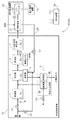
図1は、第1実施形態の燃料電池発電システムS1の構成を示す図である。燃料電池発電システムは、燃料改質装置10と燃料電池装置20と制御装置30とを備える。制御装置30は、燃料改質装置10及び燃料電池装置20の動作を制御する。
<First Embodiment>
The fuel cell power generation system S1 (S) of the first embodiment will be described below with reference to the drawings.
FIG. 1 is a diagram illustrating a configuration of a fuel cell power generation system S1 according to the first embodiment. The fuel cell power generation system includes a
燃料改質装置10は、脱硫器1と水蒸気生成器2と改質器3と燃焼器4と変成器5と電気ヒータ6と一酸化炭素除去器7とを有する。
脱硫器1は、供給される都市ガスなどの炭化水素系の原燃料に含まれる硫黄化合物を脱硫処理する脱硫触媒1aを有する。脱硫器1へ供給する原燃料の流量は、制御装置30が、バルブV1の開度を調節して制御する。脱硫器1で脱硫処理された脱硫処理済ガスは、その後、改質器3へ供給される。従って、制御装置30が、脱硫器1へ供給する原燃料の流量を調節することで、その後に改質器3で生成される改質ガスの量が調節され、最終的には、燃料電池21のアノードに供給される水素量が調節される。つまり、制御装置30は、燃料電池21の発電出力(例えば、電圧センサVで検出される電圧)を上昇させるのであれば、バルブV1の開度を大きくして脱硫器1へ供給する原燃料の流量を増加させる制御を行えばよい。
The
The desulfurizer 1 includes a
水蒸気生成器2は、燃焼器4から排出された燃焼排ガスを通流させる加熱部2bと、バルブV3を介して供給される水を加熱部2bによる加熱にて蒸発させる蒸発部2aとを有する。蒸発部で2a発生された水蒸気は、脱硫後の原燃料と共に改質器3へ供給される。蒸発部2aに供給する水の流量は、制御装置30が、バルブV3の開度を調節して制御する。例えば、制御装置30は、燃料電池21の発電出力(例えば、電圧センサVで検出される電圧)を上昇させる際、上述した脱硫器1への原燃料の供給量の増加と合わせて、蒸発部2aに供給する水の流量を増加させる制御を行えばよい。蒸発部2aに供給される水の流量は、改質器3に供給される水蒸気の量と比例する。
The
燃焼器4は、可燃性のガスを燃焼して燃焼熱を発生させる。可燃性ガスとしては、燃料電池21から排出されたアノード排ガス(発電反応に用いられなかった水素を含むガス)又は上述した都市ガス等の原燃料、或いは、その両方を用いることができる。制御装置30は、バルブV2の開度を調節して、燃焼器4に供給する原燃料の流量を制御でき、及び、アノード排ガス路23に設けられるバルブV4の開度を調節して、燃料電池21から燃焼器4へアノード排ガス路23を介して供給するアノード排ガスの流量を制御できる。つまり、制御装置30は、バルブV2、V4の開度を調節することで、燃焼器4の発熱量を制御できる。
The
改質器3は、燃焼器4で発生された燃焼熱を利用して原燃料を水蒸気改質して改質ガスを生成する。原燃料が、メタンを主成分とする天然ガスである場合、改質器3では、燃焼器4による例えば650℃〜750℃程度の加熱下でメタンと水蒸気とが下記の反応式にて改質反応して、水素と一酸化炭素と二酸化炭素を含むガスに改質処理される。
The
〔化1〕
CH4+H2O→CO+3H2
〔化2〕
CH4+2H2O→CO2+4H2
[Chemical formula 1]
CH 4 + H 2 O → CO + 3H 2
[Chemical formula 2]
CH 4 + 2H 2 O → CO 2 + 4H 2
変成器5は、改質器3にて生成された改質ガスに含まれる一酸化炭素を低減するように処理する。具体的には、変成器5では、銅−亜鉛系、鉄−クロム系などの一酸化炭素変成触媒5aの触媒作用によって、改質ガス中の一酸化炭素と水蒸気とが、例えば150℃〜300℃程度の反応温度で下記の反応式にて変成反応して、一酸化炭素が二酸化炭素に変成処理される。
The
〔化3〕
CO+H2O→CO2+H2
[Chemical formula 3]
CO + H 2 O → CO 2 + H 2
加えて、変成器5は、一酸化炭素変成触媒5aの温度を検出する温度検出手段としての温度センサTを有する。本実施形態では、温度センサTは変成器5の内部の後段部分、即ち、出口に近い付近の一酸化炭素変成触媒5aの温度を測定可能な位置に設けられている。また、変成器5には、一酸化炭素変成触媒5aを加熱可能な加熱手段Hとしての電気ヒータ6が装着される。
In addition, the
一酸化炭素除去器7は、変成器5から排出される変成処理済ガス中に残留している一酸化炭素を除去する。具体的には、一酸化炭素除去器7においては、ルテニウムや白金、パラジウム、ロジウム等の一酸化炭素除去触媒7aの触媒作用によって、100℃〜200℃程度の反応温度で変成処理済ガス中に残っている一酸化炭素が、添加された空気中の酸素によって酸化される。その結果、一酸化炭素濃度の低い(例えば10ppm以下)、水素リッチな燃料ガスが生成される。
The carbon monoxide remover 7 removes carbon monoxide remaining in the modified gas exhausted from the
以上のようにして燃料改質装置10で生成された水素を主成分とする燃料ガスは、燃料電池装置20が有する燃料電池21のアノード(図示せず)に供給される。また、燃料電池21のカソード(図示せず)には酸素(空気)が供給される。燃料電池21で発電された直流電力はパワーコンディショナー22によって所定の電力に変換された後、電力負荷装置40に供給される。燃料電池21で発電された電力の電圧は、電圧計Vによって計測される。また、上述したように、燃料電池21から排出されるアノード排ガス(発電反応に用いられなかった水素を含むガス)は、アノード排ガス路23を通じて燃焼器4に可燃性ガスとして供給される。
本実施形態で特に想定する燃料電池21は、電極触媒の一酸化炭素による被毒が問題となるような固体高分子形燃料電池やリン酸形燃料電池である。
The fuel gas mainly composed of hydrogen generated in the
The
次に、一酸化炭素変成触媒5aの劣化について説明する。
燃料改質装置10の積算運転時間が長期間になると、各機器の性能が低下することがある。例えば、変成器5が有する一酸化炭素変成触媒5aは長期間の使用に伴って劣化する(即ち、変成処理能力が低下する)。そして、一酸化炭素変成触媒5aの変成処理能力が低下するにつれて、変成器5から排出される変成処理済ガスに含まれる一酸化炭素の量が増加し、最終的には、燃料電池21へ到達する一酸化炭素の量も増加する。その結果、一酸化炭素による燃料電池21の電極触媒の被毒の影響が大きくなり、燃料電池21の発電電圧の低下へと至る。
Next, deterioration of the carbon
When the accumulated operation time of the
従って、本実施形態では、制御装置30は、一酸化炭素変成触媒5aが劣化発生条件を満たした状態にあり且つ温度センサTによる検出温度が基準温度未満である状態において、改質器3での改質ガスの生成量を増加させるとき、電気ヒータ6の動作を変化させて一酸化炭素変成触媒5aの温度を上昇させる制御、即ち、一酸化炭素変成触媒5aの活性を一時的に高める制御を行う。
Therefore, in this embodiment, the
具体的には、制御装置30は、一酸化炭素変成触媒5aが劣化発生条件を満たしているか否かを判定する。本実施形態における劣化発生条件は、改質器3への原燃料の供給量に対する燃料電池装置20の出力電圧が基準電圧未満であるか否か、又は、燃料電池装置20の出力電圧に対する改質器3への原燃料の供給量が基準供給量以上であるか否か、又は、燃料改質装置10の積算運転時間が基準積算時間以上であるか否か、である。
Specifically, the
〔劣化発生条件の判定〕
例えば、一酸化炭素変成触媒5aによる変成処理能力が低下すると、変成器5から排出される変成処理済ガスに含まれる一酸化炭素の量が相対的に増加するため、改質器3への原燃料の供給量に変化がなくても燃料電池21の発電電圧が低下することがある。そこで、制御装置30は、改質器3への原燃料の供給量に対する燃料電池装置20の基準出力電圧の関係を記憶装置(図示せず)に複数個記憶しておき、燃料改質装置10の運転中に流量センサ8で検出される改質器3への原燃料の供給量に対する、電圧センサVで検出される燃料電池装置20の出力電圧の関係を随時検証する。そして、制御装置30は、改質器3への原燃料の供給量に対する燃料電池装置20の出力電圧が基準電圧未満である場合、一酸化炭素変成触媒5aが劣化発生条件を満たしていると判断する。
[Determination of degradation conditions]
For example, when the conversion treatment capacity of the carbon
或いは、一酸化炭素変成触媒5aによる変成処理能力が低下すると、変成器5から排出される変成処理済ガスに含まれる一酸化炭素の量が相対的に増加するため、燃料電池21から同じ発電電圧を得るのに必要とする改質器3への原燃料の供給量が増加することがある。そこで、制御装置30は、燃料電池装置20の出力電圧に対する改質器3への原燃料の基準供給量の関係を記憶装置(図示せず)に複数個記憶しておき、燃料改質装置10の運転中に電圧センサVで検出される燃料電池装置20の出力電圧に対する、流量センサ8で検出される改質器3への原燃料の供給量の関係を随時検証する。そして、制御装置30は、燃料電池装置20の出力電圧に対する改質器3への原燃料の供給量が基準供給量以上である場合、一酸化炭素変成触媒5aが劣化発生条件を満たしていると判断する。
Alternatively, when the shift treatment capacity of the carbon
また或いは、燃料改質装置10の積算運転時間が基準積算時間以上になると、一酸化炭素変成触媒5aが経年劣化していると見なしてもよい。そこで、制御装置30は、燃料改質装置10の積算運転時間と、記憶装置に記憶している基準積算時間とを随時比較する。そして、制御装置30は、燃料改質装置10の積算運転時間が基準積算時間以上になると、一酸化炭素変成触媒5aが劣化発生条件を満たしていると判断する。
Alternatively, when the accumulated operation time of the
〔触媒温度の判定〕
更に、制御装置30は、一酸化炭素変成触媒5aの温度を検出する温度センサTの検出温度が基準温度(例えば、130℃)未満であるか否かを判定する。一酸化炭素変成触媒5aの温度を監視するのは、触媒温度と触媒活性とが関連するからである。つまり、触媒活性が低いと(即ち、一酸化炭素変成触媒5aの変成処理能力が低下していると)、一酸化炭素変成触媒5aの温度は過剰に低くなる。尚、上述したように、触媒活性が正常であれば、一酸化炭素変成触媒5aの温度が例えば約150℃〜約300℃の範囲で変成器5は運転継続される。
[Determination of catalyst temperature]
Furthermore, the
以上のように、制御装置30は、一酸化炭素変成触媒5aが劣化発生条件を満たした状態にあることを確認し、且つ、一酸化炭素変成触媒5aの温度を検出する温度センサTの検出温度が基準温度未満であることを確認した場合に、一酸化炭素変成触媒5aが劣化しているという確定判断を下す。そして、制御装置30は、一酸化炭素変成触媒5aが劣化しているという確定判断を記憶装置へ記憶しておく。
As described above, the
その後、制御装置30は、例えば、電力負荷装置40の電力需要が増大するなどの理由により、燃料電池21の発電出力を上昇させるタイミングであるか否か(即ち、改質ガスの生成量を増加させるタイミングであるか否か)を判定する。改質ガスの生成量を増加させるということは、変成器5において変成処理するべきガス量(即ち、変成処理負荷)が増加するということである。従って、変成器5の一酸化炭素変成触媒5aの変成処理能力が低下した状態のままでは、変成処理するべきガス量の増加に対応できず、変成処理しきれなかった多くの一酸化炭素を燃料電池21へ供給してしまうことになる。
Thereafter, the
そこで、本実施形態では、制御装置30は、一酸化炭素変成触媒5aが劣化しているという上記確定判断を行った状態において、改質器3での改質ガスの生成量を増加させるとき、加熱手段Hとしての電気ヒータ6の動作を変化させて一酸化炭素変成触媒5aの温度を上昇させる制御を行う。電気ヒータ6の動作を変化させるということは、非動作状態にある電気ヒータ6を動作状態に切り替えること、及び、既に動作状態にある電気ヒータの出力を変更すること(例えば、加熱量が小さい動作状態から加熱量が大きい動作状態に変化させること)の両方の概念を含む。つまり、電気ヒータ6の動作を変化させて一酸化炭素変成触媒5aの温度を上昇させることで、触媒活性を高めることができる。従って、触媒活性を高めることで、変成処理可能なガス量が増加するので、変成器5から排出される変成処理済ガスに含まれる一酸化炭素の量、即ち、燃料電池21へ供給される一酸化炭素の量を相対的に少なくできる。
Therefore, in the present embodiment, when the
図2は、加熱手段Hとしての電気ヒータ6を動作させた場合の燃料改質装置10の運転状態の推移を示す実施例のグラフである。具体的には、制御装置30が制御する電気ヒータ6の動作状態、温度センサTが検出する一酸化炭素変成触媒5a温度、及び、流量センサ8が検出する原燃料ガス流量の推移を示すグラフである。
FIG. 2 is a graph of an example showing the transition of the operating state of the
図2において、制御装置30は、時刻tsにおいて、燃料電池21の発電出力を上昇させるタイミングであると判定している。尚、制御装置30は、この時刻tsよりも前に、一酸化炭素変成触媒5aが劣化発生条件を満たした状態にあり且つ温度センサTによる一酸化炭素変成触媒5aの検出温度が基準温度(例えば、130℃)未満である状態にあるとの確定判断を下しているものとする。図2では、時刻ts以前の一酸化炭素変成触媒5aの温度は約120℃であるので上記基準温度未満である。そして、制御装置30は、時刻tsにおいて、燃料電池21の発電出力を増加させるべく、バルブV1の開度を調節して原燃料の供給量を増加させ始め且つバルブV3の開度を調節して水蒸気生成器2に供給する水の量を増加させ始める。
In FIG. 2, the
加えて、制御装置30は、原燃料及び水の供給量を増加させ始めるのと同時に(或いは、その前後から)、電気ヒータ6を加熱作動させて一酸化炭素変成触媒5aの温度を上昇させる。図2の例では、制御装置30は、電気ヒータ6を断続的に加熱作動させているが、電気ヒータ6を連続的に加熱作動させてもよい。図2に示すように、電気ヒータ6を加熱作動させた後、一酸化炭素変成触媒5aの温度は約150℃前後まで上昇している。また、図2に示す例では、原燃料及び水の供給量を増加側に変化させている間は一酸化炭素変成触媒5aの温度が上記基準温度以上となるように、電気ヒータ6を加熱作動させている。
図2に示すような燃料電池21の発電出力の上昇、即ち、変成処理が要求されるガス量の増大を行っても、変成器5はガスを充分に変成処理して、燃料電池21は問題なく動作した。
In addition, simultaneously with starting to increase the supply amounts of raw fuel and water (or from before and after), the
Even if the power generation output of the
これに対して、図4は、加熱手段Hとしての電気ヒータ6を加熱作動させなかった場合の燃料改質装置10の運転状態の推移を示す比較例のグラフである。電気ヒータ6を加熱作動させなかったこと以外の条件は、図2の実施例と同様である。この比較例の場合、原燃料の供給量が3L/minを超えた後、時刻t10において、変成器5の出口に設けてある一酸化炭素濃度の検出センサ(図示せず)が基準値以上の一酸化炭素を検出した(即ち、基準値以上の一酸化炭素が変成処理されずに変成器5をスリップした)ために制御装置30が燃料改質装置10の運転を停止させた。つまり、触媒活性が低下したままの一酸化炭素変成触媒5aを有する変成器5は、要求されるガス量の変成処理を充分に行えなかった。逆に言うと、図2に示した実施例では、電気ヒータ6で加熱された一酸化炭素変成触媒5aを有する変成器5は、要求されるガス量の変成処理を充分に行えていたということである。
On the other hand, FIG. 4 is a graph of a comparative example showing the transition of the operating state of the
以上のように、本実施形態では、制御装置30は、一酸化炭素変成触媒5aが劣化発生条件を満たした状態にあり且つ温度センサTによる検出温度が基準温度未満である状態において、改質器3での改質ガスの生成量を増加させるとき、加熱手段Hとしての電気ヒータ6の動作を変化させて一酸化炭素変成触媒5aの温度を上昇させる。つまり、制御装置30は、一酸化炭素変成触媒5aの温度を上昇させることで、一酸化炭素変成触媒5aの活性を高めることができる。従って、触媒活性を高めることで、変成処理可能なガス量が増加するので、変成器5から排出される変成処理済ガスに含まれる一酸化炭素の量、即ち、燃料電池21へ供給される一酸化炭素の量を許容値以下にできる。更に、本実施形態では、制御装置30が一酸化炭素変成触媒5aの活性を高めるのは、改質器3での改質ガスの生成量を増加させるときであるので、他のタイミングでは一酸化炭素変成触媒5aの活性を高めなくてよい。従って、燃料改質装置10の運転に要するエネルギが必要以上に上昇することを避けることができる。
As described above, in this embodiment, the
<第2実施形態>
第2実施形態の燃料電池発電システムS2(S)は、燃料改質装置10が電気ヒータ6を備えない点で第1実施形態の燃料電池発電システムS1と異なっている。以下に第2実施形態の燃料電池発電システムS2について説明するが、第1実施形態と同様の構成については説明を省略する。
Second Embodiment
The fuel cell power generation system S2 (S) of the second embodiment is different from the fuel cell power generation system S1 of the first embodiment in that the
第2実施形態では、制御装置30は、燃焼器4を、一酸化炭素変成触媒5aを加熱可能な加熱手段Hとして用いる。上述したように、燃焼器4は、可燃性ガスを燃焼して得られる燃焼熱によって改質器3を加熱する装置である。また、燃焼器4で加熱される改質器3から排出される改質ガスは変成器5に流入することを考慮すると、燃焼器4で発生される熱は改質ガスを介して変成器5にも伝えられていると言える。加えて、燃料改質装置10の内部で燃焼器4と変成器5とが断熱材などを間に挟みながらも互いに近接して設けられている場合、燃焼器4の筐体から放射された熱は、変成器5にも伝わる。従って、燃焼器4の発熱量が大きくなれば、変成器5に伝わる熱も大きくなる。つまり、燃焼器4は、燃焼熱によって一酸化炭素変成触媒5aを加熱可能な加熱手段Hとして機能する。
In 2nd Embodiment, the
具体的には、制御装置30は、上記第1実施形態と同様に決定される一酸化炭素変成触媒5aを加熱すべき時期において、バルブV2の開度を調節して燃焼器4への原燃料の供給量を増加させることで、燃焼器4の発熱量を増加させる。その結果、一酸化炭素変成触媒5aは加熱手段Hとしての燃焼器4の燃焼熱によって加熱される。
Specifically, the
<別実施形態>
<1>
上記実施形態において、温度センサTが変成器5の内部の後段部分、即ち、出口に近い付近の一酸化炭素変成触媒5aの温度を測定可能な位置に設けられている例を説明したが、温度センサTが変成器5の他の部位の温度を測定するように改変してもよい。
加えて、上記実施形態では、温度の数値や基準値等を具体的に例示したが、それらの数値や基準値は適宜変更可能である。上述したように、温度の測定部位や測定方法が変われば、基準温度等も変化する。
<Another embodiment>
<1>
In the above embodiment, the temperature sensor T is described as an example in which the temperature sensor T is provided at a position where the temperature of the carbon
In addition, in the above embodiment, the numerical values and reference values of the temperature are specifically exemplified, but these numerical values and reference values can be changed as appropriate. As described above, the reference temperature and the like change when the temperature measurement site and the measurement method change.
<2>
上記実施形態において、制御装置30が、改質器3での改質ガスの生成量を基準量よりも増加させるときにのみ、上述したような加熱手段Hの加熱作動を行うように改変してもよい。例えば、改質器3での改質ガスの生成量が基準量よりも多い期間は常に加熱手段Hの加熱作動を行い、改質器3での改質ガスの生成量を増加させるとしてもその生成量が基準量以下であれば、加熱手段Hの加熱作動を行わないような改変も可能である。また、その基準量を一酸化炭素変成触媒5aの劣化状態に応じて随時変更してもよい。
<2>
In the above embodiment, the
<3>
上記実施形態において、制御装置30が、上述したような加熱手段Hとしての電気ヒータ6及び燃焼器4を併用して、一酸化炭素変成触媒5aを加熱させるような変更も可能である。
<3>
In the said embodiment, the
本発明は、燃料電池発電システムを良好に運転するために利用可能である。 The present invention can be used to operate a fuel cell power generation system satisfactorily.
3 改質器
4 燃焼器
5 変成器
5a 一酸化炭素変成触媒
6 電気ヒータ
10 燃料改質装置
20 燃料電池装置
30 制御装置
H 加熱手段
T 温度センサ(温度検出手段)
3
Claims (4)
前記燃料改質装置は、原燃料を改質して水素を主成分とし一酸化炭素を含む改質ガスを生成する改質器と、前記改質ガスに含まれる一酸化炭素を二酸化炭素に変成する一酸化炭素変成触媒を有する変成器と、前記一酸化炭素変成触媒の温度を検出する温度検出手段と、前記一酸化炭素変成触媒を加熱可能な加熱手段とを有し、
前記制御装置は、前記一酸化炭素変成触媒が劣化発生条件を満たした状態にあり且つ前記温度検出手段による検出温度が基準温度未満である状態において、前記改質器での前記改質ガスの生成量を増加変化させている途中では、前記加熱手段の動作を変化させて前記一酸化炭素変成触媒の温度を前記基準温度以上に上昇させ、前記改質器での前記改質ガスの生成量を増加変化させないときは、前記加熱手段の動作を変化させることによって前記一酸化炭素変成触媒の温度を前記基準温度以上に上昇させることは行わない燃料電池発電システム。 A fuel reformer that reforms raw fuel to generate a gas mainly composed of hydrogen, a fuel cell device that generates power using a gas mainly composed of hydrogen generated by the fuel reformer, and A fuel cell power generation system comprising a control device for controlling the operation of each device,
The fuel reformer reforms a raw fuel to generate a reformed gas mainly containing hydrogen and containing carbon monoxide, and converts the carbon monoxide contained in the reformed gas into carbon dioxide. A converter having a carbon monoxide conversion catalyst, temperature detecting means for detecting the temperature of the carbon monoxide conversion catalyst, and heating means capable of heating the carbon monoxide conversion catalyst,
The control device generates the reformed gas in the reformer in a state where the carbon monoxide conversion catalyst satisfies a deterioration occurrence condition and a temperature detected by the temperature detecting means is lower than a reference temperature. the way that the amount is increased changes in operation to change the said heating means to raise the temperature of the carbon monoxide shift catalyst than the reference temperature, the generation amount of the reformed gas in the reformer A fuel cell power generation system that does not raise the temperature of the carbon monoxide shift catalyst to the reference temperature or higher by changing the operation of the heating means when the increase is not changed .
前記燃焼器は、前記燃焼熱によって前記一酸化炭素変成触媒を加熱可能な前記加熱手段として機能する請求項1〜3の何れか一項に記載の燃料電池発電システム。 The fuel reformer has a combustor that heats the reformer with combustion heat obtained by burning a combustible gas,
The fuel cell power generation system according to any one of claims 1 to 3, wherein the combustor functions as the heating unit capable of heating the carbon monoxide shift catalyst with the combustion heat.
Priority Applications (1)
| Application Number | Priority Date | Filing Date | Title |
|---|---|---|---|
| JP2010252182A JP5592760B2 (en) | 2010-11-10 | 2010-11-10 | Fuel cell power generation system |
Applications Claiming Priority (1)
| Application Number | Priority Date | Filing Date | Title |
|---|---|---|---|
| JP2010252182A JP5592760B2 (en) | 2010-11-10 | 2010-11-10 | Fuel cell power generation system |
Publications (2)
| Publication Number | Publication Date |
|---|---|
| JP2012104384A JP2012104384A (en) | 2012-05-31 |
| JP5592760B2 true JP5592760B2 (en) | 2014-09-17 |
Family
ID=46394538
Family Applications (1)
| Application Number | Title | Priority Date | Filing Date |
|---|---|---|---|
| JP2010252182A Active JP5592760B2 (en) | 2010-11-10 | 2010-11-10 | Fuel cell power generation system |
Country Status (1)
| Country | Link |
|---|---|
| JP (1) | JP5592760B2 (en) |
Families Citing this family (1)
| Publication number | Priority date | Publication date | Assignee | Title |
|---|---|---|---|---|
| JP2013004418A (en) * | 2011-06-20 | 2013-01-07 | Toshiba Fuel Cell Power Systems Corp | Fuel cell power generation system and method for controlling heater of carbon monoxide converter in fuel cell power generation system |
Family Cites Families (5)
| Publication number | Priority date | Publication date | Assignee | Title |
|---|---|---|---|---|
| JP2003217636A (en) * | 2002-01-23 | 2003-07-31 | Matsushita Electric Ind Co Ltd | Modification catalyst degradation determining unit, and hydrogen generator |
| JP2004305942A (en) * | 2003-04-08 | 2004-11-04 | Nissan Motor Co Ltd | Catalytic reaction apparatus, fuel modification system, fuel cell system |
| JP4827405B2 (en) * | 2004-12-17 | 2011-11-30 | パナソニック株式会社 | Hydrogen generator and fuel cell system using the same |
| JP5049028B2 (en) * | 2007-02-22 | 2012-10-17 | パナソニック株式会社 | Hydrogen generator, operating method thereof, and fuel cell system including the same |
| JP5379353B2 (en) * | 2007-03-12 | 2013-12-25 | 大阪瓦斯株式会社 | Temperature control system of reformer in fuel cell device |
-
2010
- 2010-11-10 JP JP2010252182A patent/JP5592760B2/en active Active
Also Published As
| Publication number | Publication date |
|---|---|
| JP2012104384A (en) | 2012-05-31 |
Similar Documents
| Publication | Publication Date | Title |
|---|---|---|
| JP4105758B2 (en) | Fuel cell system | |
| KR20070050322A (en) | Reformer and fuel cell system using the same | |
| US11081709B2 (en) | Fuel cell system | |
| JP4870909B2 (en) | Fuel cell power generator | |
| JP4939114B2 (en) | Fuel processing apparatus and fuel cell system | |
| JP4827405B2 (en) | Hydrogen generator and fuel cell system using the same | |
| JP2007137719A (en) | Fuel reforming apparatus, and fuel cell power generation apparatus using it and its operation method | |
| JP2004047438A (en) | Operation control method of fuel cell generator | |
| JP2006219328A (en) | Hydrogen generation apparatus and fuel cell system using the same | |
| JP5379353B2 (en) | Temperature control system of reformer in fuel cell device | |
| JP5592760B2 (en) | Fuel cell power generation system | |
| JP2007200771A (en) | Reforming catalyst temperature control system and control method of fuel cell power generator | |
| JP5389520B2 (en) | Fuel cell reformer | |
| JP5353214B2 (en) | Hydrogen generator and fuel cell power generation system including the same | |
| JP4466049B2 (en) | Water flow control method for reforming steam | |
| JP2017027668A (en) | Fuel battery system and operation method for the same | |
| JP5001690B2 (en) | Fuel reformer | |
| JP2006120421A (en) | Fuel cell power generation system | |
| JP2015140285A (en) | Method for operating hydrogen-containing gas generation apparatus, and hydrogen-containing gas generation apparatus | |
| JP2006073215A (en) | Fuel cell system | |
| JP4917791B2 (en) | Fuel cell system | |
| JP2010275118A (en) | Hydrogen production apparatus | |
| JP6684610B2 (en) | Fuel cell system | |
| JP6722893B2 (en) | Fuel cell system | |
| JP2011210637A (en) | Fuel cell system |
Legal Events
| Date | Code | Title | Description |
|---|---|---|---|
| A621 | Written request for application examination |
Free format text: JAPANESE INTERMEDIATE CODE: A621 Effective date: 20130619 |
|
| A977 | Report on retrieval |
Free format text: JAPANESE INTERMEDIATE CODE: A971007 Effective date: 20140320 |
|
| A131 | Notification of reasons for refusal |
Free format text: JAPANESE INTERMEDIATE CODE: A131 Effective date: 20140403 |
|
| A521 | Written amendment |
Free format text: JAPANESE INTERMEDIATE CODE: A523 Effective date: 20140528 |
|
| TRDD | Decision of grant or rejection written | ||
| A01 | Written decision to grant a patent or to grant a registration (utility model) |
Free format text: JAPANESE INTERMEDIATE CODE: A01 Effective date: 20140703 |
|
| A61 | First payment of annual fees (during grant procedure) |
Free format text: JAPANESE INTERMEDIATE CODE: A61 Effective date: 20140801 |
|
| R150 | Certificate of patent or registration of utility model |
Ref document number: 5592760 Country of ref document: JP Free format text: JAPANESE INTERMEDIATE CODE: R150 |