JP5591251B2 - Aircraft towing vehicle without tow bar - Google Patents
Aircraft towing vehicle without tow bar Download PDFInfo
- Publication number
- JP5591251B2 JP5591251B2 JP2011537011A JP2011537011A JP5591251B2 JP 5591251 B2 JP5591251 B2 JP 5591251B2 JP 2011537011 A JP2011537011 A JP 2011537011A JP 2011537011 A JP2011537011 A JP 2011537011A JP 5591251 B2 JP5591251 B2 JP 5591251B2
- Authority
- JP
- Japan
- Prior art keywords
- aircraft
- tow
- vehicle
- tow vehicle
- speed
- Prior art date
- Legal status (The legal status is an assumption and is not a legal conclusion. Google has not performed a legal analysis and makes no representation as to the accuracy of the status listed.)
- Expired - Fee Related
Links
Images


Classifications
-
- G—PHYSICS
- G06—COMPUTING; CALCULATING OR COUNTING
- G06F—ELECTRIC DIGITAL DATA PROCESSING
- G06F11/00—Error detection; Error correction; Monitoring
- G06F11/30—Monitoring
-
- B—PERFORMING OPERATIONS; TRANSPORTING
- B60—VEHICLES IN GENERAL
- B60P—VEHICLES ADAPTED FOR LOAD TRANSPORTATION OR TO TRANSPORT, TO CARRY, OR TO COMPRISE SPECIAL LOADS OR OBJECTS
- B60P3/00—Vehicles adapted to transport, to carry or to comprise special loads or objects
- B60P3/06—Vehicles adapted to transport, to carry or to comprise special loads or objects for carrying vehicles
- B60P3/11—Vehicles adapted to transport, to carry or to comprise special loads or objects for carrying vehicles for carrying aircraft
-
- B—PERFORMING OPERATIONS; TRANSPORTING
- B64—AIRCRAFT; AVIATION; COSMONAUTICS
- B64F—GROUND OR AIRCRAFT-CARRIER-DECK INSTALLATIONS SPECIALLY ADAPTED FOR USE IN CONNECTION WITH AIRCRAFT; DESIGNING, MANUFACTURING, ASSEMBLING, CLEANING, MAINTAINING OR REPAIRING AIRCRAFT, NOT OTHERWISE PROVIDED FOR; HANDLING, TRANSPORTING, TESTING OR INSPECTING AIRCRAFT COMPONENTS, NOT OTHERWISE PROVIDED FOR
- B64F1/00—Ground or aircraft-carrier-deck installations
- B64F1/04—Launching or towing gear
- B64F1/10—Launching or towing gear using self-propelled vehicles
-
- B—PERFORMING OPERATIONS; TRANSPORTING
- B64—AIRCRAFT; AVIATION; COSMONAUTICS
- B64F—GROUND OR AIRCRAFT-CARRIER-DECK INSTALLATIONS SPECIALLY ADAPTED FOR USE IN CONNECTION WITH AIRCRAFT; DESIGNING, MANUFACTURING, ASSEMBLING, CLEANING, MAINTAINING OR REPAIRING AIRCRAFT, NOT OTHERWISE PROVIDED FOR; HANDLING, TRANSPORTING, TESTING OR INSPECTING AIRCRAFT COMPONENTS, NOT OTHERWISE PROVIDED FOR
- B64F1/00—Ground or aircraft-carrier-deck installations
- B64F1/22—Ground or aircraft-carrier-deck installations installed for handling aircraft
- B64F1/225—Towing trucks
- B64F1/227—Towing trucks adapted for directly connecting to aircraft, e.g. trucks without tow-bars
-
- B—PERFORMING OPERATIONS; TRANSPORTING
- B60—VEHICLES IN GENERAL
- B60S—SERVICING, CLEANING, REPAIRING, SUPPORTING, LIFTING, OR MANOEUVRING OF VEHICLES, NOT OTHERWISE PROVIDED FOR
- B60S13/00—Vehicle-manoeuvring devices separate from the vehicle
-
- F—MECHANICAL ENGINEERING; LIGHTING; HEATING; WEAPONS; BLASTING
- F16—ENGINEERING ELEMENTS AND UNITS; GENERAL MEASURES FOR PRODUCING AND MAINTAINING EFFECTIVE FUNCTIONING OF MACHINES OR INSTALLATIONS; THERMAL INSULATION IN GENERAL
- F16H—GEARING
- F16H61/00—Control functions within control units of change-speed- or reversing-gearings for conveying rotary motion ; Control of exclusively fluid gearing, friction gearing, gearings with endless flexible members or other particular types of gearing
- F16H61/38—Control of exclusively fluid gearing
- F16H61/40—Control of exclusively fluid gearing hydrostatic
- F16H61/4043—Control of a bypass valve
-
- F—MECHANICAL ENGINEERING; LIGHTING; HEATING; WEAPONS; BLASTING
- F16—ENGINEERING ELEMENTS AND UNITS; GENERAL MEASURES FOR PRODUCING AND MAINTAINING EFFECTIVE FUNCTIONING OF MACHINES OR INSTALLATIONS; THERMAL INSULATION IN GENERAL
- F16H—GEARING
- F16H61/00—Control functions within control units of change-speed- or reversing-gearings for conveying rotary motion ; Control of exclusively fluid gearing, friction gearing, gearings with endless flexible members or other particular types of gearing
- F16H61/38—Control of exclusively fluid gearing
- F16H61/40—Control of exclusively fluid gearing hydrostatic
- F16H61/42—Control of exclusively fluid gearing hydrostatic involving adjustment of a pump or motor with adjustable output or capacity
-
- Y—GENERAL TAGGING OF NEW TECHNOLOGICAL DEVELOPMENTS; GENERAL TAGGING OF CROSS-SECTIONAL TECHNOLOGIES SPANNING OVER SEVERAL SECTIONS OF THE IPC; TECHNICAL SUBJECTS COVERED BY FORMER USPC CROSS-REFERENCE ART COLLECTIONS [XRACs] AND DIGESTS
- Y02—TECHNOLOGIES OR APPLICATIONS FOR MITIGATION OR ADAPTATION AGAINST CLIMATE CHANGE
- Y02T—CLIMATE CHANGE MITIGATION TECHNOLOGIES RELATED TO TRANSPORTATION
- Y02T50/00—Aeronautics or air transport
- Y02T50/80—Energy efficient operational measures, e.g. ground operations or mission management
Description
本発明は、概して航空機地上移動用システムに関し、より具体的にはこのようなシステムの地上車の制御法に関する。 The present invention relates generally to aircraft ground movement systems, and more particularly to ground vehicle control methods for such systems.
航空機牽引車は、多くの場合、空港の地上位置間で航空機を牽引するために提供され、これにより、航空機が自身の動力で移動する必要性を取り除き、ジェット燃料を節約する。当該牽引車には、降着装置を牽引車と接続する牽引棒を設けることができるか、または、当該牽引車は、牽引棒が設けられず、典型的に降着装置が牽引車のシャーシ上に直接位置する、牽引棒を有しないものであり得る。 Aircraft towing vehicles are often provided to tow aircraft between ground locations at airports, thereby eliminating the need for the aircraft to move on its own power and saving jet fuel. The tow vehicle can be provided with a tow bar that connects the landing gear with the tow vehicle, or the tow vehicle is not provided with a tow bar, and typically the landing gear is directly on the tow vehicle chassis. It may be one that does not have a tow bar located.
本発明の一態様によれば、航空機の降着装置を受け、それによって、航空機を牽引するように構成された、牽引棒を有しない航空機牽引車が提供され、当該牽引車は、
・その上に降着装置の少なくとも一部を受けるように構成されたシャーシと、
・軌道に沿った方向に牽引車を移動するように構成され、かつ可変角度斜板油圧モータおよび制御可能なバイパス経路バルブと連結された可変角度斜板油圧ポンプを備える推進装置であって、バイパス経路が閉じられた状態にあるとき、推進配置を作動させて牽引車の速度および牽引力のうちの少なくとも1つを増加させるためにポンプとモータとの間に油圧流体が循環するように、そして、バイパス経路が開かれた状態にあるとき、油圧流体の少なくとも大部分が、牽引車の回転速度および牽引力のうちの少なくとも1つを減少させるために、バイパス経路バルブを介してモータの全域にわたって循環するように構成される、推進配置と、
・少なくとも牽引車と航空機の間の速度差に起因する方向に、シャーシによって降着装置へ及ぼされる力を、直接または間接に測定するように構成された少なくとも1つの力センサと、
・力センサと連通し、降着装置へシャーシによって及ぼされる力が、少なくとも、推進配置の利用可能な動力、ポンプおよびモータ斜板、並びに、バイパス経路バルブの状態を調整することによって、所定値以下で(例えば、牽引車の動作の間に)維持されるように、牽引車の動作の1つ以上のパラメータを変更するように構成された、制御装置と、
を備える。
According to one aspect of the present invention, there is provided an aircraft tow vehicle having a tow bar configured to receive an aircraft landing gear and thereby tow an aircraft, the tow vehicle comprising:
A chassis configured to receive at least a portion of the landing gear thereon;
A propulsion device comprising a variable angle swash plate hydraulic pump configured to move the towing vehicle in a direction along the track and connected to a variable angle swash plate hydraulic motor and a controllable bypass path valve, the bypass device Hydraulic fluid circulates between the pump and motor to activate the propulsion arrangement to increase at least one of the speed and power of the towing vehicle when the path is closed, and When the bypass path is in an open state, at least a majority of the hydraulic fluid circulates across the motor through the bypass path valve to reduce at least one of the traction vehicle rotational speed and traction force. Configured as a propulsion arrangement, and
At least one force sensor configured to measure directly or indirectly the force exerted by the chassis on the landing gear, at least in the direction due to the speed difference between the tow vehicle and the aircraft;
The force exerted by the chassis on the landing gear in communication with the force sensor is below a predetermined value by adjusting at least the available power of the propulsion arrangement, the pump and motor swash plate, and the state of the bypass path valve A controller configured to change one or more parameters of the operation of the tow vehicle to be maintained (eg, during operation of the tow vehicle);
Is provided.
用語「牽引棒を有しない」は、本明細書および請求項で使用するとき、牽引棒(すなわち、牽引車のシャーシと航空機の降着装置の間を結合させる棒または他の接続装置)のない航空機牽引車の部類に関することを十分に理解されたい。牽引棒を有しない航空機牽引車においては、降着装置が概してシャーシ上に直接位置するか、または、降着装置の重量がシャーシ内の領域へと導かれる。 The term “having no tow bar” as used herein and in the claims refers to an aircraft without a tow bar (ie, a bar or other connecting device that couples between a tow truck chassis and an aircraft landing gear). Please fully understand the category of towing vehicles. In aircraft tow vehicles without a tow bar, the landing gear is generally located directly on the chassis, or the weight of the landing gear is directed to an area within the chassis.
用語「制御装置」は、本明細書および請求項で使用するとき、例えばそれぞれが特定機能を実行する、2つ以上の制御装置を含むが、これらに限定されない最広義の用語で理解されるべきであることをさらに十分に理解されたい。 The term “control device” as used herein and in the claims should be understood in the broadest term, including but not limited to two or more control devices each performing a specific function, for example. Please understand more fully.
牽引棒を有しない航空機牽引車は、バイパス経路が閉鎖されたときに、牽引車の自由な動作のために、モータ全体の油圧流体の自由流動を可能にする油圧モータ三方弁をさらに備える場合がある。 An aircraft tow truck that does not have a tow bar may further include a hydraulic motor three-way valve that allows free flow of hydraulic fluid throughout the motor for free movement of the tow truck when the bypass path is closed. is there.
バイパス経路は、斜板ポンプから、油圧流体の流れがそれる、バイパス経路が開いた後の制動期間と関連する場合があり、制御装置は、バイパス経路の状態を制御するように更に構成され、バルブは、制動期間より非常に短い応答期間を特徴とする。 The bypass path may be associated with a braking period after the bypass path is opened where the flow of hydraulic fluid diverts from the swash plate pump, and the controller is further configured to control the state of the bypass path; The valve is characterized by a response period that is much shorter than the braking period.
推進駆動モジュールは、バイパス経路の状態を制御するバルブをさらに備える場合があり、当該バルブは、油圧ポンプおよびモータの斜板の共振周期より遥かに短い応答期間を特徴とする。 The propulsion drive module may further comprise a valve that controls the state of the bypass path, which valve is characterized by a response period that is much shorter than the resonant period of the hydraulic pump and the swashplate of the motor.
油圧モータの容量を調整するように、制御装置を構成することができる。 The control device can be configured to adjust the capacity of the hydraulic motor.
斜板ポンプの制御角度を調整するように、制御装置を構成することができる。このようにして、制御装置は、牽引車の速度を制御し、それによって航空機の降着装置に作用する力を制御することができる。 The control device can be configured to adjust the control angle of the swash plate pump. In this way, the control device can control the speed of the tow vehicle and thereby the force acting on the landing gear of the aircraft.
斜板ポンプの制御角度の速い変化を誘導するように、制御装置を構成することができる。これによって、航空機の降着装置に作用する力が力閾値を超えることを、制御装置が防止することが可能になる。 The controller can be configured to induce fast changes in the control angle of the swash plate pump. Thereby, the control device can prevent the force acting on the landing gear of the aircraft from exceeding the force threshold value.
斜板ポンプの制御角度の遅い変化を誘導するように、制御装置を構成することができる。例えば、これは、牽引棒を有しない航空機牽引車を所望の速度にするために有用であり得る。 The controller can be configured to induce a slow change in the control angle of the swash plate pump. For example, this may be useful to bring an aircraft tow vehicle without a tow bar to a desired speed.
斜板ポンプの制御角度を調整するためにフィードフォワード工程(すなわち、システムへの入力の混乱を、混乱の出現を予期してまたは混乱の出現と同時に、システム装置を調整するために使用することができる制御形態)を利用するように、制御装置を構成することができる。
A feedforward process (i.e., disruption of input to the system can be used to adjust the system equipment in anticipation of or at the same time as the occurrence of the disruption to adjust the control angle of the swash plate pump. The control device can be configured to utilize a control form that can be used.
牽引棒を有しない航空機牽引車は、降着装置とシャーシ間のエネルギを吸収するように配置されたエネルギ吸収器をさらに備える場合がある。 An aircraft tow vehicle that does not have a tow bar may further comprise an energy absorber arranged to absorb energy between the landing gear and the chassis.
動作の1つ以上のパラメータの変更が、牽引車に速度および/または牽引力を減少させるような効果を有し、かつ/または、そのように導くことができる。 Changes in one or more parameters of operation can have and / or be guided in such a way as to reduce the speed and / or traction force on the towing vehicle.
シャーシは、降着装置の一部を受け、かつ、少なくともシャーシ上でその方向に移動可能であるように、シャーシ上に取り付けられるように構成された支持アセンブリを備える場合がある。このような場合、シャーシ上で、少なくともその方向に支持アセンブリによって及ぼされる力を測定するように、力センサを構成することができる。 The chassis may include a support assembly configured to be mounted on the chassis so as to receive a portion of the landing gear and to be movable in that direction at least on the chassis. In such cases, the force sensor can be configured to measure the force exerted by the support assembly at least in that direction on the chassis.
速度、方向、加速度および減速度から成る群から、動作のパラメータを選択することができる。 The operating parameters can be selected from the group consisting of velocity, direction, acceleration and deceleration.
1つ以上の外因に少なくとも基づいて、シャーシによって降着装置へ及ぼされる(予測された)合力を算出するように、制御装置を構成することができる。当該外因は、
・牽引車が通過する、航空機移動面に沿ったさまざまな位置での傾斜に関するデータと、
・航空機および牽引車に影響を及ぼす風力に関するデータと、
・航空機移動面に沿ったさまざまな位置での航空機および/または牽引車の転がり摩擦力に関するデータと、
・障害物に関するデータと、
を含む群から選択することができる。
The controller can be configured to calculate the (predicted) resultant force exerted by the chassis on the landing gear based at least on one or more external factors. The external cause is
・ Data on tilt at various positions along the plane of the aircraft, through which the tow truck passes,
Data on wind power affecting aircraft and towing vehicles;
Data on rolling friction forces of aircraft and / or tow trucks at various positions along the plane of aircraft travel;
・ Data on obstacles,
Can be selected from the group comprising
傾斜に関するデータを、傾斜角検出機能により提供することができる。 Data about the tilt can be provided by the tilt angle detection function.
傾斜に関するデータを、データベースに傾斜データとして予め設定および保存することができ、制御装置は、航空機移動面上の牽引車の位置を決定して、傾斜データをその位置と関連づけるようにさらに構成される。 Inclination data can be preset and stored as inclination data in a database, and the controller is further configured to determine the position of the tow vehicle on the aircraft moving surface and associate the inclination data with that position. .
転がり摩擦力に関するデータを、データベースに摩擦データとして予め設定および記憶することができ、制御装置は、航空機移動面上の牽引車の位置を決定して、摩擦データをその位置と関連づけるようにさらに構成される。 Data relating to rolling friction can be pre-set and stored as friction data in a database, and the controller is further configured to determine the position of the tow vehicle on the aircraft moving surface and associate the friction data with that position. Is done.
航空機経路に沿った障害物を検出するように、牽引車を構成することができる。
The tow vehicle can be configured to detect obstacles along the aircraft path.
例えば電子フライトバッグによって、無線で遠隔管理センターと通信するように、制御装置を構成することができる。 The control device can be configured to communicate wirelessly with a remote management center, for example, with an electronic flight bag.
牽引棒を有しない航空機牽引車は、航空機内の同様の装置と無線で通信するように構成された電子フライトバッグをさらに備える場合がある。 An aircraft tow vehicle that does not have a tow bar may further include an electronic flight bag configured to wirelessly communicate with similar devices in the aircraft.
本発明の別の態様によれば、航空機を牽引するための方法が提供され、当該方法は、
・上に航空機の降着装置の少なくとも一部を受けるように構成されたシャーシと、
・軌道に沿った方向に牽引車を移動するように構成され、可変角度斜板油圧モータおよび制御可能なバイパス経路バルブと連結された可変角度斜板油圧ポンプを備える推進装置であって、バイパス経路が閉じられた状態にあるとき、推進配置を作動させて牽引車の速度および牽引力のうちの少なくとも1つを増加させるためにポンプとモータとの間に油圧流体が循環するように、および、バイパス経路が開かれた状態にあるとき、油圧流体の少なくとも大部分が、牽引車の回転速度および牽引力のうちの少なくとも1つを減少させるために、バイパス経路バルブを介してモータの全域にわたって循環するように構成される、推進配置と、
を備える、牽引棒を有しない航空機牽引車を提供することを含み、当該方法は、降着装置へシャーシによって及ぼされる力が、少なくとも、推進配置の利用可能な動力、ポンプおよびモータ斜板、並びに、バイパス経路バルブの状態を調整することによって、所定値以下で維持されるように、牽引車の動作の1つ以上のパラメータを変更して、牽引車に航空機を牽引させることをさらに含む。
According to another aspect of the invention, a method for towing an aircraft is provided, the method comprising:
A chassis configured to receive at least a portion of an aircraft landing gear on top;
A propulsion device configured to move a tow vehicle in a direction along a track and comprising a variable angle swash plate hydraulic motor and a variable angle swash plate hydraulic pump connected to a controllable bypass route valve, the bypass route The hydraulic fluid circulates between the pump and the motor to activate the propulsion arrangement to increase at least one of the tow vehicle speed and traction force when the is closed, and bypass When the path is in an open state, at least a majority of the hydraulic fluid is circulated across the motor through the bypass path valve to reduce at least one of the tow vehicle rotational speed and traction force. A propulsion arrangement composed of:
Providing an aircraft tow vehicle without a tow bar, the method comprising: the force exerted by the chassis on the landing gear is at least the power available in the propulsion arrangement, the pump and motor swash plate, and The method further includes changing one or more parameters of the operation of the tow vehicle to cause the tow vehicle to tow the aircraft to be maintained below a predetermined value by adjusting a state of the bypass path valve.
上記の通りに牽引車を提供することができる。 A towing vehicle can be provided as described above.
本発明のさらなる一態様によれば、航空機の降着装置を受け、それによって、航空機を牽引するように構成された、牽引棒を有しない航空機牽引車が提供され、当該牽引車は、
・その上に降着装置の少なくとも一部を受けるように構成されたシャーシと、
・軌道に沿った方向に牽引車を移動するように構成された推進配置と、
・牽引棒を有しない航空機牽引車の実際の速度とその所定の所望の速度との間で比較して、
o実際の速度が、所望の速度より低い場合に、および
o実際の速度が、比較より前の、事前に決められた期間に、事前に決められた速度範囲内に維持された場合に、
牽引棒を有しない航空機牽引車の実際の速度を維持するように推進配置に指示するよう構成された制御装置と、
を備える。
According to a further aspect of the present invention, there is provided an aircraft tow vehicle having no tow bar configured to receive an aircraft landing gear and thereby tow an aircraft, the tow vehicle comprising:
A chassis configured to receive at least a portion of the landing gear thereon;
A propulsion arrangement configured to move the tow vehicle in a direction along the track;
-Compare between the actual speed of an aircraft tow truck without a tow bar and its predetermined desired speed,
o if the actual speed is lower than the desired speed, and o if the actual speed is maintained within a predetermined speed range for a predetermined period prior to the comparison,
A controller configured to instruct the propulsion arrangement to maintain the actual speed of the aircraft towing vehicle without the tow bar;
Is provided.
航空機パイロットにより制御された航空機の制動および減速を検出するように、制御装置をさらに構成することができ、当該制御装置は、
・実際の速度が、所望の速度より高い場合に、および
・航空機パイロットに制御された航空機の制動および減速のうちの少なくとも1つが検出された場合に、
実際の速度を維持するように推進配置に指示するようにさらに構成される。
The controller may be further configured to detect aircraft braking and deceleration controlled by the aircraft pilot, the controller being
When the actual speed is higher than the desired speed, and when at least one of braking and deceleration of the aircraft controlled by the aircraft pilot is detected,
Further configured to instruct the propulsion arrangement to maintain the actual speed.
航空機パイロットにより制御された制動が検出される場合に、所望の速度と一致させるように、に牽引棒を有しない航空機牽引車の実際の速度を変えるように推進配置に指示するように、制御装置をさらに構成することができる。 A controller to instruct the propulsion arrangement to change the actual speed of the aircraft tow truck without the tow bar to match the desired speed if braking controlled by the aircraft pilot is detected Can be further configured.
牽引棒を有しない航空機牽引車を、航空機牽引の間、常に正の牽引力が加えられるようにさらに構成することができる。 An aircraft tow vehicle without a tow bar can be further configured so that a positive traction force is always applied during aircraft towing.
牽引棒を有しない航空機牽引車を、最大許容疲れ荷重の超過から降着装置をリアルタイムで保護するようにさらに構成することができる。 An aircraft tow vehicle without a tow bar can be further configured to protect the landing gear in real time from exceeding the maximum allowable fatigue load.
所望の速度を算出するように、制御装置をさらに構成することができる。 The controller can be further configured to calculate a desired speed.
所望の速度に対応した所望の牽引力を算出するように、制御装置をさらに構成することができる。 The control device can be further configured to calculate a desired tractive force corresponding to the desired speed.
少なくとも牽引車の位置に基づいて、所望の速度を算出するように、制御装置をさらに構成することができる。 The control device can be further configured to calculate a desired speed based at least on the position of the towing vehicle.
更に、制御装置は、少なくとも、牽引車の位置および少なくとも1つの他の牽引車の位置に基づいて、所望の速度を算出するように構成されてもよい。 Furthermore, the control device may be configured to calculate a desired speed based at least on the position of the towing vehicle and the position of at least one other towing vehicle.
少なくとも、牽引車の位置、並びに、その牽引車と少なくとも1つの経路を共有する少なくとも1つの他の牽引車の位置および速度に基づいて所望の速度を算出するように、制御装置をさらに構成することができる。 Further configuring the controller to calculate a desired speed based at least on the position of the towing vehicle and the position and speed of at least one other towing vehicle sharing at least one route with the towing vehicle. Can do.
少なくとも、牽引車の位置、および、牽引位置の端に牽引車が到着する所望の時刻に基づいて所望の速度を算出するように、制御装置をさらに構成することができる。 The control device can be further configured to calculate a desired speed based at least on the position of the tow vehicle and the desired time at which the tow vehicle arrives at the end of the tow position.
少なくとも、牽引車の位置、牽引場所の端に別の牽引車が到着する推定時刻、および、牽引位置の端に牽引車が到着する所望の時刻に基づいて所望の速度を算出するように、制御装置をさらに構成することができる。 Control to calculate the desired speed based on at least the position of the tow vehicle, the estimated time of arrival of another tow vehicle at the end of the tow location, and the desired time of arrival of the tow vehicle at the end of the tow position The device can be further configured.
牽引棒を有しない航空機牽引車は、牽引車の速度および位置に関する情報を送信するように構成された送信器をさらに備えることができる。この情報は、例えば、航空機操縦席、少なくとも1つの他の牽引車、または遠隔管理センターに送信することができる。 An aircraft tow vehicle without a tow bar may further comprise a transmitter configured to transmit information regarding the speed and position of the tow vehicle. This information can be transmitted to, for example, an aircraft cockpit, at least one other tow vehicle, or a remote management center.
牽引棒を有しない航空機牽引車は、少なくとも1つの他の牽引車の速度および位置に関する情報を遠隔管理センターから受信するように構成された受信器をさらに備えることができる。 An aircraft tow vehicle that does not have a tow bar may further comprise a receiver configured to receive information about the speed and position of at least one other tow vehicle from a remote management center.
牽引棒を有しない航空機牽引車は、センサを利用することによって、少なくとも1つの他の牽引車の速度および位置を検出するように構成された検出器を備えることができ、当該制御装置は、他の牽引車の速度および位置に少なくとも基づいて所望の速度を算出するように構成される。 An aircraft tow vehicle that does not have a tow bar may be provided with a detector configured to detect the speed and position of at least one other tow vehicle by utilizing a sensor, the control device comprising: A desired speed is calculated based at least on the speed and position of the towing vehicle.
牽引位置の端に到着する所望の時刻、および、牽引場所の端に他の牽引車が到着する推定時刻に基づいて所望の速度を算出するように、制御装置をさらに構成することができる。 The controller can be further configured to calculate a desired speed based on a desired time of arrival at the end of the tow position and an estimated time of arrival of another tow vehicle at the end of the tow location.
また、本発明のなおさらなる一態様によれば、牽引棒を有しない航空機牽引車を制御するための方法が提供され、当該方法は、
・牽引経路の少なくとも一部を牽引車と共有することが予想される、少なくとも1つの他の牽引車の速度および位置に関する情報を得ることと、
・牽引車の速度および位置、並びに、その情報に少なくとも基づいて、牽引車の所望の速度を算出することと、
を含む。
Also according to yet a further aspect of the invention, a method for controlling an aircraft tow vehicle without a tow bar is provided, the method comprising:
Obtaining information on the speed and position of at least one other tow vehicle that is expected to share at least a portion of the tow route with the tow vehicle;
Calculating the desired speed of the tow vehicle based at least on the speed and position of the tow vehicle and the information;
including.
当該方法は、牽引位置の端に牽引車が到着する所望の時刻に基づいて、所望の速度を算出することをさらに含むことができる。 The method may further include calculating a desired speed based on a desired time at which the tow vehicle arrives at the end of the tow position.
当該方法は、牽引場所の端にもう1つの牽引車が到着する推定時刻に基づいて、牽引棒を有しない航空機牽引車の所望の速度を算出することをさらに含むことができる。 The method may further include calculating a desired speed of the aircraft tow truck that does not have a tow bar based on an estimated time at which another tow truck arrives at the end of the towing site.
当該方法は、牽引車の速度および位置に関する情報を他の牽引車に送信することをさらに含むことができる。 The method may further include transmitting information regarding the speed and position of the tow vehicle to another tow vehicle.
当該方法は、牽引車の速度および位置に関する情報を遠隔管理センターに送信すること、並びに、速度および位置に関する情報から他の牽引車の情報をそこから受信することをさらに含むことができる。
The method may further include transmitting information on the tow vehicle speed and position to the remote management center and receiving information on other tow vehicles from the information on speed and position therefrom.
牽引車は、センサを利用して、少なくとも1つの他の牽引車の速度および位置に関する情報を得ることができる。 The tow vehicle can use sensors to obtain information regarding the speed and position of at least one other tow vehicle.
本発明のなおさらなる一態様によれば、航空機の降着装置を受け、それによって、航空機を牽引するように構成された、牽引棒を有しない航空機牽引車が提供され、当該牽引車は、
・上に降着装置の少なくとも一部を受けるように構成されたシャーシと、
・軌道に沿った方向に牽引車を移動するように構成された推進配置と、
・上記の通りに操作するように構成された制御装置と、
を備える。
According to yet a further aspect of the present invention, there is provided an aircraft tow vehicle having no tow bar configured to receive an aircraft landing gear and thereby tow an aircraft, the tow vehicle comprising:
A chassis configured to receive at least a portion of the landing gear on top;
A propulsion arrangement configured to move the tow vehicle in a direction along the track;
A control device configured to operate as described above;
Is provided.
本発明は、以下の図に関連して行われる以下の詳細な説明から、より完全に、理解および評価されるであろう。
空港ゲートから離陸滑走路へ航空機を地上移動させるための、ロボットまたは半ロボット牽引車の制御システムが提供される。牽引車は、燃料消費を抑えそして汚染を最小化するために、航空機ジェットエンジンを使用することなく航空機を地上移動させるように設計される。制御装置は、したがって、2重の機能、すなわち、牽引車の牽引速度をリアルタイムで、および常に制御する(それによって、航空機エンジンに代わる)機能、並びに、牽引車牽引力を調整する(それによって、静荷重および疲れ荷重制限を超えないことで航空機降着装置(例えば、前脚またはNLG)を保護し、並びに、これによって、航空機降着装置のライフサイクルに影響を与えない)機能を有する。したがって、いくつかの制御および制御量が相互に関連および相互依存している多入力、多出力(MIMO)制御概念が、制御装置の動作を指示するために、提供される。 A robotic or semi-robot towed vehicle control system is provided for moving an aircraft from the airport gate to the take-off runway. Tow vehicles are designed to move an aircraft to the ground without using an aircraft jet engine to reduce fuel consumption and minimize pollution. The control device thus adjusts the tow vehicle traction force (and thereby to the tow vehicle traction force), as well as the function to control the tow vehicle traction speed in real time and constantly (thus replacing the aircraft engine). Protects aircraft landing gear (eg, front legs or NLG) by not exceeding load and fatigue load limits, and thereby does not affect the life cycle of the aircraft landing gear. Thus, a multiple-input, multiple-output (MIMO) control concept, in which several controls and controlled variables are interrelated and interdependent, is provided to direct the operation of the controller.
本明細書において提供される記載は、航空機のジェットエンジンを使用することなくゲートから離陸滑走路まで航空機を地上移動させるためのロボットまたは半ロボット牽引車に関する。牽引車は、航空機パイロットにより制御された地上移動モードで動作することができ、そこで、航空機パイロットは、航空機が自身の動力で移動しているかのように、操縦およびブレーキ操作をし、そして、牽引車速度は、制御装置により制御される。地上移動の完了時に、牽引車は、空港の命令および制御システムに制御されて、ゲートの前押し戻し位置へ自律的に戻ることができる。牽引車のドライバが押し戻し動作を実行することができ、実行後、ドライバは牽引車から離れ、航空機のパイロットが、地上移動の間、牽引車を制御する。牽引車は、航空機の地上移動の間、自律動作モードで動作することができる。「自律」という用語は、空港の命令、制御および通信システム管理下の動作を含んで、広義で本明細書全体において使用され、この動作は、航空機のパイロットによるオーバーライドを受ける場合がある。 The description provided herein relates to a robot or semi-robot towing vehicle for moving an aircraft to the ground from a gate to a take-off runway without using the aircraft's jet engine. The tow vehicle can operate in a ground movement mode controlled by the aircraft pilot, where the aircraft pilot maneuvers and brakes as if the aircraft is moving with its own power, and towing The vehicle speed is controlled by the control device. Upon completion of ground movement, the tow vehicle can be controlled autonomously by the airport command and control system to autonomously return to the gate's forward push position. The driver of the tow vehicle can perform a pushback operation, after which the driver leaves the tow vehicle and the aircraft pilot controls the tow vehicle during ground movement. The tow vehicle can operate in an autonomous mode of operation during aircraft ground movement. The term “autonomous” is used throughout this specification in a broad sense, including operations under airport command, control and communication system control, which may be subject to override by an aircraft pilot.
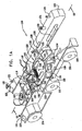
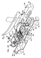
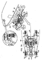
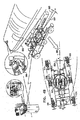
牽引棒を有しない航空機牽引車100を例解する、図1A、図1Bおよび図1Cに対して、ここで参照が行われる。本出願の受託者に指定された国際公開第WO2008/139440号は、本開示に適用可能な多くの原理を教示し、その全内容は、必要に応じて、追加的または代替的詳細、特徴および/または技術的背景の適切な教示のために、本明細書における参照により、本明細書によって組み込まれる。図1A、図1Bおよび図1Cに示されるように、牽引棒を有しない航空機牽引車100は、前方の操縦可能な車輪104および106、後方の操縦可能な車輪108および110、並びに、中間の操縦不可能な車輪112および114を含む、6つの車輪に支持されるシャーシ102を備える。また、車輪112および114は、代わりに、操縦可能であり得ると十分に理解される。それぞれ参照番号115、116、117および118によって示される、操縦可能な車輪104、106、108および110の回転中心は、1つの長方形の頂点を定めることができ、その長さAは、牽引車100の同じ側面上の、前方および後方のそれぞれの車輪の回転中心間の分離によって定められ、その幅Bは、前方のそれぞれの車輪104および106の回転中心115と116の間、並びに、後方のそれぞれの車輪108および110の回転中心117と118の間の分離によって定められる。
Reference is now made to FIGS. 1A, 1B and 1C, which illustrate an
車輪104、106、108、110、112および114のそれぞれを、制御装置119からの速度およびトルク制御信号に反応して車両ディーゼルモータ(図示せず)に駆動される、対応した油圧ポンプ(図示せず)を原動力とする対応した油圧モータ(図示せず)により、制御可能に駆動することができる。操縦可能な車輪104、106、108および110のそれぞれは、制御装置119からの操縦制御信号に応答して、1つ以上の操縦ピストン(図示せず)により操縦可能であり得る。車輪、油圧ポンプおよびディーゼルモータは、軌道に沿った方向へ牽引車を移動するように構成された、推進配置の一部を構成する。
Each of the
ハンドル120、ブレーキ(図示せず)および必要に応じて他の制御装置を任意に含み得るドライバ制御インタフェースアセンブリは、押し戻しの前および間、および/または、非常事態または牽引車制御システムの故障時に、牽引棒を有しない航空機牽引車100の動作をドライバが調節することを可能にするように、制御装置119と連動することができる。牽引棒を有しない航空機牽引車100は、離陸地点に近づくか、または、離陸地点へ地上移動するために、制御装置119を介して、「航空機パイロット管理」(PIC)モードで動作することができる。離陸地点の近くで、制御装置119は、空港管理統制センターから、または、例えばGPSセンサ若しくは何らかの適切な他の牽引車位置センサなどの、牽引車位置センサ121から受け取った命令に応答して、自動または(セーフティドライバによる)手動で、航空機から牽引車100を分離し、牽引車100は、制御装置119の制御で動作し、自律、または、セーフティドライバによって動かされる手動で、離陸地点から所望の前押し戻し位置へと戻る。牽引車100は、風センサ122、例えばVelodyne(登録商標)社によって、HDL―64Eの名前で販売されているようなレーダーおよび/またはレーザセンサなどの、制御装置119に出力をする1つ以上の障害物検出センサ123、および、例えば遠隔管理統制センターによる、牽引車100の遠隔運転を可能にする1つ以上の運転カメラ124、を備え得る。運転カメラ124は、オペレータが牽引車100の上、または、牽引車の近くのさまざまな位置を見ることができるように、選択可能なパンおよび傾きを有するよう回転可能であり得る。
The driver control interface assembly, which may optionally include a
回転可能な航空機降着装置の車輪支持アセンブリ125は、枢動可能かつ回転可能に、水平基盤アセンブリ126に取り付けられる。支持アセンブリ125の、参照番号127により示される定常状態回転中心は、操縦可能なそれぞれの車輪104、106、108および110の、回転中心115、116、117および118によって定められる長方形の幾何中心にあり得る。
A rotatable aircraft landing gear
水平基盤アセンブリ126は、シャーシに対するアセンブリの限定された運動の自由度を許容する方法で、シャーシ102に連結され、そして、複数のエネルギ吸収ピストン128を備え得るエネルギ吸収器アセンブリにより係合される。エネルギ吸収ピストンのそれぞれは、シャーシ102および水平基線アセンブリ126に枢動可能に連結される。力センサ129は、ロードセルでもよく、エネルギ吸収ピストン128のそれぞれと関連していてもよい。センサは、制御装置119に出力し、それにより車両の加速および減速を制御する際に使用される。
The
水平基盤アセンブリ126マットは周囲の基底要素130を備え、基底要素は、前方の一組の掛けられた支持体132上で横へ伸びる支持ロッド131から懸架されることによって、そして、シャーシ102に枢動可能に取り付けられた後方の一組の受け渡し支持体132に懸架されることによって、シャーシ102に枢動可能に取り付けられる。掛けられた支持体132は、枢動可能に取り付けられたエネルギ吸収ピストン128により係合される。掛けられた支持体132への周囲の基底要素130の取り付けを、回転可能な軸133によって行うことができ、周囲の基底要素130と一体的に当該軸を形成してもしなくてもよい。
The
支持アセンブリ125を、高耐荷重軸受135と係合した、アセンブリから外側へ伸びている一組の回動軸134によって、基盤126に枢動可能かつ回転可能に取り付けることができ、次いで、軸受は、基盤126に形成された360°周囲のベアリングレース136と係合する。この配置は、基底要素130、水平基盤アセンブリ126およびシャーシ102に対する、支持アセンブリ125の比較的低摩擦の回転可能性および傾斜可能性を提供する。
The
直立したフレーム140は、支持アセンブリ上に航空機降着装置車輪の位置を合わせるために、支持アセンブリ125に固定して取り付けられる。航空機降着装置車輪ストップバー142を、支持アセンブリを航空機降着装置車輪の異なるサイズに適応させるために、支持アセンブリ125に固定されたストップバー位置決めピストン144によって、直立したフレーム140に対して選択できるように配置することができる。支持アセンブリ125の回転方向を、電位差計などの、回転センサ145により検出することができ、当該センサは、支持アセンブリ回転方向の入力を制御装置119に提供する。支持アセンブリ125の回転方向を、支持アセンブリ回転モータ146により調節することができる。
The
選択して位置決め可能なクランプアセンブリ147を、支持アセンブリ125に取り付け、そして直立したフレーム140に連結することができる。クランプアセンブリ147は、航空機降着装置車輪の回転中心が、できる限り正確に支持アセンブリの回転中心127にあるように、つまり、上記したように、操縦可能な車輪104、106、108および110の回転中心によって定められた長方形の幾何中心にあるように、支持アセンブリ125上に航空機降着装置車輪を選択的に締め付けるように動作する。
A selectively
ロードセルなどの力センサ148は、例えば、牽引されている航空機の加速、減速および/または速度に対する、牽引車100の加速、減速および/または速度の違いに起因した、航空機降着装置車輪、つまり航空機降着装置に加えられる水平面での力を検出するべく航空機降着装置車輪を係合するために、クランプアセンブリ147の前方接面上、および、ストップバー142の後方接面上へ取り付けられる。
A
傾斜した航空機降着装置の車輪ランプ150を、基底要素130に取り付けることができる。一組の航空機降着装置の車輪係合ピストンアセンブリ152を、航空機降着装置を押しおよび持ち上げるように、並びに、支持アセンブリ125上に航空機降着装置車輪を配置するように、提供することができる。
A tilted aircraft landing
力センサ148は、牽引車の動作の軌道に沿って、一般に水平な、少なくとも1つの方向に降着装置に加えられる力を検出するように動作することができる。この力は、航空機パイロットにより制御された牽引車減速を引き起こす航空機の制動、または、牽引車加速の結果であり得る。制御装置119は、とりわけ航空機パイロットにより制御された制動を示す、力センサの出力情報に応答して、少なくとも一部は動作し、結果として航空機の減速をもたらし、牽引車100の車輪を動かす油圧モータに速度およびトルク制御信号を提供する。制御とは、例えば、結果的に牽引車の減速および/または加速をもたらす航空機パイロットにより制御された制動によって、航空機の降着装置に損害を与えない最大に許容された力まで、航空機の降着装置に加えられる力を低下および制限するようなことである。
The
回転センサ145は、航空機の降着装置を介して航空機パイロットの操縦によって引き起こされる、基盤アセンブリ126に対する支持アセンブリ125の回転を検出するように動作することができ、制御装置119は、回転センサ145の出力情報に基づき、このようにして航空機パイロットの操縦命令に応答し、操縦可能な車輪104、106、108および110の操縦を制御するように動作する。
The rotation sensor 145 is operable to detect rotation of the
力センサ129および148は、結果として生じる、少なくとも1つの全体に水平な方向に降着装置に加えられる力を検出することができ、その結果、制御装置119は、少なくとも1つの力センサの出力情報を利用して、パイロットに制御された制動、および、以下の入力情報のうちの少なくとも1つを検出して、少なくとも1つの力フィードバックループを使用することによって、牽引車の加速および減速を制御するように動作する:
・牽引車100が通過する航空機移動面に沿った、さまざまな位置の既知の傾斜によって誘導される力の表示であって、それらの位置は、位置検出機能によって制御装置に対して特定される、表示、
・航空機に加えられる風力の表示。空港および/または牽引車に取り付けられた風センサから、制御装置に供給されている風力に関する情報、および
・牽引車が通過する航空機移動面に沿ったさまざまな位置の、牽引車および航空機の既知の転がり摩擦力の表示であって、それらの位置は、位置検出機能によって制御装置に対して特定される、表示。
The
An indication of forces induced by known tilts at various positions along the plane of aircraft travel through which the
-An indication of wind power applied to the aircraft. Information about the wind power supplied to the control device from wind sensors attached to the airport and / or tow truck, and known tow trucks and aircraft at various positions along the plane of the aircraft traveled by the tow truck A display of rolling friction forces, the position of which is specified to the control device by a position detection function.
制御装置119は、例えば、制御装置119に組み込んだ適切な空港地図、並びに、牽引車100および航空機の移動経路に沿った牽引車100の位置を示した牽引車位置センサの出力情報、を利用するなどの、牽引車および航空機が通過する移動経路に沿った既知の制限速度に基づいて、少なくとも1つの速度フィードバックループを使用することによって、牽引車100の速度をさらに制御するように動作することができる。
The
単一または一組のレーザ測距装置154を、航空機の前後軸と牽引車100の前後軸の間の角度関係を確認するために、牽引車100のシャーシ102に取り付けることができる。航空機の前後軸と牽引車100の前後軸の間の角度関係を、例えば図4Aから図4Eで本明細書の下記に説明する、自律地上移動モードで使用することができる。
A single or a set of
図2Aで見られるように、牽引車100は、押し戻しを待つ航空機202に向けて、矢印200によって示される方向に、牽引車ドライバの制御によって移動する。図2Bは、ランプ150に置かれた降着装置車輪204を例解する。図2Cは、航空機降着装置を押しおよび持ち上げるため、並びに、支持アセンブリ125上に航空機降着装置車輪を配置するために、降着装置車輪204に係合して配置された降着装置車輪係合ピストンアセンブリ152を例解する。図2Dは、特定の航空機202の特定の航空機降着装置車輪204に対応するための、ストップバー位置決めピストン144による、直立したフレーム140に対する航空機降着装置車輪ストップバー142の適切な位置決めを例解する。図2Eは、支持アセンブリ125上に押されている降着装置車輪204を例解する。
As seen in FIG. 2A, the
図2Fは、上記のように、操縦可能な車輪104、106、108および110の回転中心によって定められた長方形の幾何中心、または、幾何中心の近くにある、支持アセンブリ125の回転中心127に、航空機降着装置車輪204の回転軸が、できる限り正確に位置するように、適切に配置されたストップバー142へ、ピストンアセンブリ152によって押される航空機降着装置車輪204を例解する。
FIG. 2F illustrates the
図2Gおよび図2Hは、航空機降着装置の車輪204との係合からの個々のピストンアセンブリ152の後退と、航空機降着装置の車輪の回転中心が、できる限り正確に支持アセンブリ125の回転中心127にあるように支持アセンブリ125上へ航空機降着装置車輪を締付けるための、クランプアセンブリ147の個々のクランプの航空機降着装置車輪204との係合を例解する。図2Iは、牽引車のドライバが制御する牽引車100による、航空機202の押し戻しを例解する。図2Jは、押し戻し完了後、牽引車100から離れる牽引車のドライバを例解する。ドライバは、地上移動の全部または一部の間、牽引車100上に残ってもよく、エンジン始動後、航空機からの牽引車の離脱に関与してもよい。
2G and 2H show that the retraction of the
図3Aは、基底要素130に対して支持アセンブリ125の対応した回転を引き起こす、従来の航空機舵柄206またはペダル(図示せず)を用いた、航空機パイロットによる航空機降着装置車輪204の回転を例解する。支持アセンブリ125の回転は、回転センサ145によって、直接に直ちに検出され、回転センサ145は制御装置119へ出力情報を提供し、図6Aから図6Bに関して以下でより詳細に説明されるように、牽引車100の操縦可能な車輪104、106、108および110の即時の回転をもたらす。
FIG. 3A illustrates rotation of aircraft
制御装置119は、航空機パイロットに操縦されたときの降着装置の車輪204、つまり支持アセンブリ125の方向と、ここでは参照番号210によって示される牽引車100の前後軸との間の、角度αを示す、回転センサ145からの入力情報を受け取るフィードバック制御ループに従って、牽引車100の操縦を実行することができる。制御装置119は、図6Aから図6Cに関して以下で説明されるそれぞれの角度β1、β2、β3およびβ4で、牽引車の操縦可能な車輪104、106、108および110を回転させて、角度αがゼロとなるように牽引車100を動かす。
The
図3Bは、航空機パイロットによって示された方向へ航空機202が牽引車に引かれるように、向きが定められた牽引車100の、動作の中間段階を例解する。この段階では、支持アセンブリ125と牽引車100の前後軸210間の角度αは、図3Aに示された角度の半分であるように示されている。角度γは、航空機202に対する牽引車100の回転による、牽引車100の前後軸210と、ここでは参照番号220によって示される牽引車に牽引されている航空機202の前後軸との間で示される。
FIG. 3B illustrates an intermediate stage of operation of the
図3Cは、αがゼロであるように、航空機202の降着装置の車輪204に対して向きを定められた牽引車100を例解する。牽引車の操縦可能な車輪104、106、108および110の角度β1、β2、β3およびβ4は、それぞれ、概してゼロではないことに注意すべきである。この段階では、牽引車100の前後軸210と牽引車100によって牽引されている航空機202の前後軸220間の角度γは、航空機202が回転し始めたため、図3Bのγより小さい。
FIG. 3C illustrates the
図3Dは、航空機のパイロットがペダル222を踏むことによる、航空機202の制動を例解する。航空機202の制動は、航空機202の主脚(図示せず)のブレーキによって実行され、航空機を減速させる、つまりクランプ147の力センサ148に検出される力の作用をすぐにもたらし、力センサの出力情報は、制御装置119により受け取られ、それに応じてすぐに牽引車100を減速する。航空機202の制動と牽引車100の対応する減速の間にタイムラグがあるため、力は、後方のエネルギ吸収ピストン128に加えられて、力センサ129によってすぐに検出される。後方のエネルギ吸収ピストン128は、牽引車100に対する航空機202の制動によって引き起こされるエネルギを吸収する。この段階では、力センサ129は、力センサ148のバックアップとしての役割を果たす。
FIG. 3D illustrates the braking of the
図3Eは、以下の1つ以上の要因を考慮して、航空機移動経路に沿った予め決められた位置で予め決められた制限速度の範囲内となる航空機地上移動速度を提供するため、および、降着装置に加えられる力が予め決められた限界を超えないことを確実にするために、とりわけ力センサ148および129から受け取った入力情報に応えて、制御装置119によって調節された牽引車100の制御された加速を例解する:
・牽引車100が通過する航空機移動面に沿ったさまざまな位置の既知の傾斜によって誘導される力。ここでは牽引車に取り付けられた牽引車位置センサ121によって提供される、GPS機能などの、位置検出機能によって、制御装置119に対して特定される位置、
・航空機202に加えられる風力。例えば牽引車に取り付けられた風センサ122などの、空港または牽引車搭載の風センサから、そしてまた、選択的に空港の命令および制御機能を介して、制御装置119に供給される風力に関する情報、および
・牽引車100が通過する航空機移動面に沿ったさまざまな位置での、牽引車100および航空機202の転がり摩擦力であって、その位置は、牽引車位置センサ121によって提供された位置検出機能によって、そしてまた、選択的に空港の命令および制御機能を介して、制御装置119に識別される、転がり摩擦力。
FIG. 3E provides an aircraft ground movement speed that is within a predetermined speed limit at a predetermined position along the aircraft movement path, taking into account one or more of the following factors; and Control of towing
-Forces induced by known tilts at various positions along the plane of aircraft travel through which the
Wind force applied to
また、制御装置119は、航空機パイロットの航空機202の制動だけでなく、障害物センサ123によって検出された障害物の探知にも応答して、牽引車100を減速することもできる。牽引車の減速は、航空機と牽引車の間の調整された減速比を確実にするために、それによって、航空機202の降着装置に加えられる力を予め決められた力の制限値内に制限するために、とりわけ力センサ148および129から受け取った入力情報に応えて、制御装置119によって調節される。
Further, the
降着装置への通常の牽引力とパイロットの制動によって加えられる力を区別するために、制御装置119は、センサ120、121、122および123並びにカメラ124などの、各種センサからのデータによって示される、上で説明された1つ以上の要因を考慮する場合がある。
In order to distinguish between normal traction force on landing gear and the force applied by pilot braking, the
制御装置119は、速度制御フィードバックループを使用して牽引車の所望の速度を維持するように、牽引車100の加減速を調節することができる。制御装置119には、牽引車移動経路のさまざまな区域の、関連した牽引車制限速度を示した、組み込まれた空港地図を設けるか、または、当該地図を利用可能にすることができる。この制限速度の情報は、牽引車100の瞬間的な位置を示した情報によって調整され、当該位置を示した情報を、牽引車位置センサ121によって提供することができる。更に、制御装置119は、牽引車100の瞬間的な速度を示すナビゲーションシステムをさらに含む場合がある。フィードバックループは、牽引車100の瞬間的な位置の制限速度に実際の速度をできるだけ近づけ、そして、実際の速度が制限速度を超えないように動作する。
The
制御装置119は、例えば力制御フィードバックループを使用して、航空機202の降着装置に加えられる水平な力を、航空機総重量の4%といった許容範囲に制限するように、牽引車100の加減速を調節するように動作することもできる。制御装置119は、力センサ148および129からの入力情報を受け取り、その入力は、とりわけ、風、傾斜、転がり摩擦、並びに、航空機202および/または牽引車100の加速または減速がもたらす、航空機202の降着装置に加えられる力の合計を示す。力フィードバックループは、航空機202または牽引車100の何れかの予期しない加速または減速のための余地を選択的に残して、力センサ148および129によって検出される力を許容範囲以下に維持するように、牽引車100を加速または減速する。
The
牽引棒を有しない航空機牽引車100の自律地上移動動作のさまざまな段階を示した、図4A、図4B、図4C、図4Dおよび図4Eに対して、ここで参照が行われる。自律地上移動動作を、押し戻し完了後、牽引車100のドライバによって、または、空港管理統制センターからの命令に応答して自動で開始することができる。
Reference is now made to FIGS. 4A, 4B, 4C, 4D, and 4E, which illustrate various stages of autonomous ground movement operation of an
自律地上移動動作では、支持アセンブリ125の機能は、概して航空機の前後軸220と平行した、航空機パイロットが最後に選択した位置に降着装置車輪204の位置を維持して、水平面で降着装置に加えられる力、特にトルクをゼロまで低下させることである。その結果、牽引車100がその移動経路に沿って方向を変えても、降着装置の位置はそのままである。これは、牽引車100の大部分の操縦操作で、支持アセンブリが牽引車100の操作とは逆に回転することを意味する。
In autonomous ground movement operation, the function of the
自律牽引車制御は、力センサ148および129にすぐに検出される、主脚の航空機ブレーキを操作することによって、航空機パイロットがすぐにオーバーライドしてもよい。
Autonomous tow vehicle control may be immediately overridden by the aircraft pilot by manipulating the main leg aircraft brake, which is immediately detected by
自律地上移動は、例えば以下の入力情報の一部若しくは全部を利用して、空港を地上移動しているすべての航空機の地上移動経路および速度を調整および最適化する、空港管理統制センターの拡張C4(命令、統制、通信およびコンピュータ)機能を使用することができる:
・空港内の地上移動しているすべての航空機の位置、
・すべての航空機地上移動許可および地上移動経路の計算、および
・飛行場の気象条件および誘導路の地面移動条件。
The autonomous ground movement is an extension C4 of the airport management control center that adjusts and optimizes the ground movement paths and speeds of all aircraft moving on the ground using, for example, part or all of the following input information. (Command, control, communication and computer) functions can be used:
The position of all aircraft moving on the ground in the airport,
• calculation of all aircraft ground movement permits and ground movement paths; and • airfield weather conditions and taxiway ground movement conditions.
この拡張C4機能は、以下の機能の一部若しくは全部を提供することができる:
・滑走路侵入の回避、
・地上移動の間の最小のスタートおよびストップを保証するために、すべての航空機の最適な地上移動速度を算出すること、
・誘導路上の交通渋滞を最小化すること、および
・故障または非常事態の場合に即時のパイロットによる制御を可能にすること。
This extended C4 function can provide some or all of the following functions:
・ Avoid runway entry,
Calculate the optimal ground movement speed for all aircraft to ensure minimum start and stop during ground movement;
• minimize traffic congestion on taxiways; and • allow immediate pilot control in the event of a failure or emergency.
図4Aは、自律地上移動動作の始めの牽引車100および航空機202の初期の方向を例解する。航空機降着装置車輪204は、牽引車100の前後軸210、および、航空機の前後軸220に平行な状態である。牽引車100の操縦可能な車輪104、106、108および110も、軸210および220と平行な状態である。
FIG. 4A illustrates the initial direction of
図4Bは、例えば、C4システムに基づいて空港の命令および制御システム250から受け取った交通制御命令に応答する、制御装置119の制御下での、牽引車100の初めの回転を例解する。図4Bに示されるように、航空機パイロットは、非常時の制動を除いて、従来の航空機舵柄206またはペダル(図示せず)を使用しない。牽引車100の所望の操縦は、制御装置119からの適切な命令に応答して、牽引車100の操縦可能な車輪104、106、108および110の回転によってもたらされる。航空機202の降着装置へのトルクの作用を回避するために、支持アセンブリ125は、支持アセンブリ回転モータ146によって、牽引車の前後軸210と航空機の前後軸220の間の角度αと等しい大きさで、逆方向である角度−αだけ回転する。支持アセンブリ125の回転は、制御装置119にフィードバック出力を提供する回転センサ145によって検出される。
FIG. 4B illustrates the initial rotation of the
制御装置119は、操縦可能な車輪104、106、108および110を操縦すること、並びに、2つのフィードバック制御ループに従って、支持アセンブリ回転モータ146に支持アセンブリ125を回転させることによって、牽引車100を操縦することができる。1つのフィードバックループは、空港の命令および制御システム250によって定められた、予め決められた移動経路に牽引車100の方向が従うことを確実にする。第2のフィードバックループは、航空機の前後軸220と平行して降着装置車輪204が位置を確実に合わされるように、レーザ測距装置154を使用する。レーザ測距装置154は、牽引車100の前後軸210と航空機202の前後軸220の間の角度αを確認する。制御装置119は、降着装置車輪204が常に航空機の前後軸220と位置が合ったままであることを確実にするため、支持アセンブリ125が前後軸210に対して角度−αだけ回転することを確実にする。
The
図4Cは、牽引車100の回転の更なる段階を例解する。この段階では、牽引車100の前後軸210と航空機202の前後軸220の間の角度α、および、支持アセンブリ125と牽引車100の前後軸210の間の角度−αは、図4Bに示された角度の2倍であることが示される。
FIG. 4C illustrates a further stage of rotation of the
図4Dは、例えば航空機のパイロットが制動ペダル222を踏むといった、航空機パイロットによる自律動作モードのオーバーライドを例解する。このオーバーライドは、例えば、非常時の制動のため、および/または、図3Aから図3Eに関して上記した通り、航空機パイロットの牽引車100の制御操縦を可能にするためであり得る。航空機202の制動は、航空機202の主脚(図示せず)のブレーキによって実行され、航空機を減速、したがって、クランプ147上の力センサ148に検出される力の作用をもたらす。力センサの出力情報は、制御装置119によって受け取られ、制御装置はすぐに牽引車100を減速する。
FIG. 4D illustrates an override of the autonomous mode of operation by the aircraft pilot, for example, the aircraft pilot depressing the brake pedal 222. This override may be, for example, for emergency braking and / or to allow control piloting of the aircraft
制御装置119は、牽引車100の押し戻し運転モードを終了して、図3Aから図3Eに関して上記した通り、牽引車モードを航空機パイロット制御動作へと移す。
The
航空機202の制動と牽引車100の対応する減速の間にタイムラグがあるため、力は、後方のエネルギ吸収ピストン128に加えられて、力センサ129にすぐに検出される。後方のエネルギ吸収ピストン128は、牽引車100に対して航空機202の制動によって引き起こされるエネルギを吸収する。この段階では、力センサ129は、力センサ148のバックアップとしての役割を果たす。
Due to the time lag between the braking of the
自律モード動作への復帰は、空港の命令および制御システム250からの入力情報、または、例えばイスラエルのアストロノーティクス社から市販されている、電子フライトバッグ(EFB)を介して送信されるパイロット命令を、典型的に必要とする。
Returning to autonomous mode operation can be accomplished by using airport instructions and input information from the
図4Eは、以下の1つ以上の要因を考慮して、航空機移動経路に沿った予め決められた位置で予め決められた制限速度の範囲内となる航空機地上移動速度を提供するため、および、降着装置に加えられる力が予め決められた限界を超えないことを確実にするために、とりわけ、空港管理統制センター250並びに力センサ148および129から受け取った入力情報に応えて、制御装置119に調節された、自律動作モードの牽引車100の制御された加速を例解する:
・牽引車100が通過する航空機移動面に沿ったさまざまな位置の既知の傾斜によって誘導される力であって、その位置は、ここでは牽引車位置センサ121を取り付けた牽引車よって提供される、GPS機能などの、位置検出機能によって制御装置119に対して特定される、力、
・航空機202に加えられる風力、例えば牽引車に取り付けられた風センサ122などの、空港または牽引車搭載の風センサから、そして、空港の命令および制御機能を介して、制御装置119に供給される風力に関する情報、および
・牽引車100が通過する航空機移動面に沿ったさまざまな位置での、牽引車および航空機の転がり摩擦力であって、それらの位置は、牽引車位置センサ121によって提供された位置検出機能によって、そして、空港の命令および制御機能を介して、制御装置119に対して特定される、転がり摩擦力。
FIG. 4E provides an aircraft ground movement speed that is within a predetermined speed limit at a predetermined position along the aircraft movement path, taking into account one or more of the following factors; and In order to ensure that the force applied to the landing gear does not exceed a predetermined limit, the
A force induced by known tilts at various positions along the plane of aircraft travel through which the
• Wind power applied to the
制御装置119は、航空機パイロットの航空機202の制動だけでなく、障害物センサ123若しくは運転カメラ124の1つによって検出された障害物の探知、または、空港管理統制センター250から受け取った制御命令にも応答して、牽引車100を減速することができる。牽引車の減速は、航空機と牽引車の間の調整された減速比を確実にするために、それによって、航空機202の降着装置に加えられる力を予め決められた力の制限値内に制限するために、とりわけ力センサ148および129から受け取った入力情報に応えて、制御装置119によって調節される。
The
降着装置への通常の牽引力とパイロットの制動によって加えられる力を区別するために、制御装置119は、センサ120、121、122および123などの、各種センサからのデータによって示される、上で説明された1つ以上の要因を考慮する。
To distinguish between normal traction force on landing gear and the force applied by pilot braking, the
制御装置119は、速度制御フィードバックループを使用して牽引車の所望の速度を維持するように、牽引車100の加速および減速を調節するように動作することができる。制御装置119には、牽引車移動経路のさまざまな区域の、関連した牽引車制限速度を示した、組み込まれた空港地図を設けるか、または、当該地図を利用可能にすることができる。この制限速度の情報は、牽引車100の瞬間的な位置を示した情報によって調整され、当該位置を示した情報を、牽引車位置センサ121によって提供することができる。制御装置119は、牽引車100の瞬間的な速度を示すナビゲーションシステムをさらに含む場合がある。フィードバックループは、牽引車の瞬間的な位置の制限速度に実際の速度をできるだけ近づけ、そして、実際の速度が制限速度を超えないように動作する。
The
制御装置119は、例えば力制御フィードバックループを使用して、航空機202の降着装置に加えられる水平な力を、航空機総重量の4%といった、許容範囲に制限するように、牽引車100の加減速を調節するように動作することもできる。制御装置119は、力センサ148および129からの入力情報を受け取り、その入力情報は、とりわけ、風、傾斜、転がり摩擦、並びに、航空機202および/または牽引車100の加速または減速がもたらす、航空機202の降着装置に加えられる力の合計を示す。力フィードバックループは、航空機202または牽引車100の予期しない加速または減速のための余地を選択的に残して、力センサ148および129によって検出される力を、降着装置が許容できる力の制限値の十分に下で維持するように、牽引車100を加速または減速する。
The
牽引車100が、牽引車100および牽引された航空機202の地上移動速度が概して航空機パイロットに制御された地上移動動作モードの速度である、図4Aから図4Eに示される自律地上移動動作モードにおいて動くとき、航空機パイロットは、航空機ブレーキをかけて、航空機舵柄206による牽引車操縦を再開することで、自律システムにオーバーライドし、航空機パイロットに制御された動作モードに切り替えることが可能であり得る。航空機パイロットは、緊急事態において航空機ブレーキをかけることもできる。
The
効率的な地上移動動作は、空港のすべての航空機の地上移動が命令および制御システム250によって統合的な方法で管理され、このように、離陸するために待つ航空機の列を避けるという事実のため、自律地上移動動作モードで提供される。図4Eで見られるように、命令および制御システム250は、航空機が、地上移動の間、航空機間で所望の間隔を維持し、そして、できる限り、始動動作および停止動作を避けるように、すべての航空機の動作を統合する。
Efficient ground movement operation is due to the fact that the ground movement of all aircraft at the airport is managed in an integrated manner by the command and
牽引車の地上移動動作のため、および、離陸帯から前押し戻し位置への牽引車100の帰還のための、制御装置119を介した、空港管制塔の命令および制御システムの制御下での、牽引棒を有しない航空機牽引車100の自律動作モードのさまざまな段階を示したそれぞれの図である、図5A、図5B、図5C、図5Dおよび図5Eに対して、ここで参照が行われる。
Towing under the control of the airport control tower command and control system via the
図5A、図5Bおよび図5Cは、航空機降着装置車輪204からの牽引車100の離脱を例解する。航空機からの牽引車100の離脱は、航空機のエンジンが航空機パイロットによって始動された後、概して実行されることが十分に理解される。命令および制御システム250が、離脱を実行するように牽引車100に命令することができる。代替的には、牽引車による離脱を、離陸地点に隣接した予め決められた離脱位置で、牽引車の検出された位置によって、自動で作動することができる。制御装置119に無線で離脱命令を通信することができる。牽引車を分離する命令に応答して、クランプアセンブリ147は、航空機降着装置車輪204との締付け係合から分離され、そして、牽引車100は、前方へ移動する。その一方で、航空機パイロットは、航空機202にブレーキをかけて、航空機舵柄206を制御して、航空機降着装置車輪にランプ150を下らせ、ランプ150が航空機に対して前方に移動するように、航空機220の前後軸と平行に降着装置を保つ。
5A, 5B, and 5C illustrate the removal of the
セーフティドライバが牽引車100にいてもよく、その場合には、離脱はセーフティドライバにより従来の方法で実行することができ、セーフティドライバによる音声通信コードの切断を通常伴う。
A safety driver may be on the
図5Dは、離陸地域から前押し戻し位置までの予め決められた牽引車自律移動経路に沿った予め決められた位置での、予め決められた制限速度範囲内の牽引車移動速度を提供するために、以下の要因の1つ以上を考慮して、制御装置119によって調節された、牽引車の制御された加速および操縦を例解する:
・牽引車位置センサ121によって示される牽引車100の瞬間的な位置、
・センサ123またはカメラ124から受信された障害物探知情報、
・空港の命令および制御システム250によって提供される牽引車移動経路に沿った他の車両の位置に関するリアルタイム情報、および
・離陸位置から前押し戻し位置までの、1つ以上の予め定めた牽引車100の移動経路を示す情報;この情報を、制御装置119に保存するか、または、空港の命令および制御システム250によってリアルタイムで提供することができる。
FIG. 5D provides a tow vehicle movement speed within a predetermined speed limit range at a predetermined position along a predetermined tow vehicle autonomous movement path from the takeoff area to the forward push back position. Illustrates controlled acceleration and maneuvering of the tow vehicle, adjusted by
The instantaneous position of the
Obstacle detection information received from
• real-time information on the position of other vehicles along the tow vehicle travel path provided by the airport command and
図5Eは、前押し戻し位置で制御装置119によって調節された、牽引車の制御された減速および駐車を例解する。
FIG. 5E illustrates the controlled deceleration and parking of the towing vehicle adjusted by the
航空機202のアッカーマンステアリングを提供する、牽引棒を有しない航空機牽引車100の操縦機能のそれぞれの概略図である、図6A、図6Bおよび図6Cに対して、ここで参照が行われる。
Reference is now made to FIGS. 6A, 6B, and 6C, which are schematic views of each of the steering functions of
降着装置車輪204が航空機202の前後軸220に沿ってまっすぐ前方に操縦される航空機202を示した図6Aを見ると、以下のパラメータの記号が言及されている:
・L=降着装置車輪204の回転軸302と、ここでは参照番号306および308によって示される、主脚を結ぶ線304の間の、航空機202の前後軸220に沿った距離、
・A=牽引車100の、後部の操縦可能な車輪108および110の中心をつなぐ線310と、前部の操縦可能な車輪104および106の中心をつなぐ線312の間の、縦方向の距離、
・B=牽引車100の、車輪108および110の中心間、および、車輪104および106の中心間の横断方向の距離、および
・C=線304に沿った、主脚306と308間の距離。
Turning to FIG. 6A, which shows the
L = the distance along the
A = the longitudinal distance between the line 310 connecting the centers of the rear
B = transverse distance between the centers of the
図6Bは、牽引車100のシャーシ102に対する、支持アセンブリ125の対応した回転を引き起こす、舵柄206を使用した航空機パイロットの操縦に応答して、降着装置車輪204が角度αだけ回転した航空機202を例解する。制御装置119は、図3Aから図3Eに関して上記したように、αがゼロとなるような牽引車100の方向づけをもたらすために、牽引車の操縦可能な車輪104、106、108および110の回転をもたらす。制御装置119は、以下のパラメータに従って、図6Bで図示したように、航空機202のアッカーマンステアリングが引き起こされるように、牽引車100の動きも制御する:
・R+C/2=航空機202の瞬間的な回転半径、
・α=航空機202の前後軸220に対する降着装置車輪204の回転角度、および
・βi=牽引車100の車輪の操縦角度(i=104、106、108および110)。
FIG. 6B illustrates
R + C / 2 = instantaneous turning radius of
Α = rotational angle of the
αの関数としてのβiの計算は、以下の通りでもよい:
・L/[R+C/2]=tanα>>R=L/tanα−C/2
・tan(β108)=[L−A/2cosα−B/2sinα]/[L/tanα+A/2―B/2sinα]
・tan(β110)=[L―A/2cosα+(A/2tanα+B/2)sinα]/[L/tanα+(A/2tanα+B/2)cosα]
・tan(β104)=[L―A/2cosα+B/2sinα]/[L/tanα―A/2+B/2sinα]
・tan(β106)=[L−A/2cosα−(A/2tanα+B/2)sinα]/[L/tanα―(A/2tanα+B/2)cosα]
The calculation of β i as a function of α may be as follows:
L / [R + C / 2] = tan α >> R = L / tan α−C / 2
Tan (β 108 ) = [LA / 2 cos α−B / 2 sin α] / [L / tan α + A / 2−B / 2 sin α]
Tan (β 110 ) = [LA−2 / 2 cos α + (A / 2 tan α + B / 2) sin α] / [L / tan α + (A / 2 tan α + B / 2) cos α]
Tan (β 104 ) = [LA−2 / 2 cos α + B / 2 sin α] / [L / tan α−A / 2 + B / 2 sin α]
Tan (β 106 ) = [LA / 2 cos α− (A / 2 tan α + B / 2) sin α] / [L / tan α− (A / 2 tan α + B / 2) cos α]
図6Cは、αがゼロであるように、牽引車100を航空機202に対して再方向合わせさせる、牽引車操縦アルゴリズムに従った牽引車100の動作を例解する。図3Aから図3Eに関して上で言及されたように、制御装置119は、回転センサ145によって検出される角度αをゼロまで減らすように、前述のように操縦可能な牽引車車輪104、106、108および110を回転させることによって、牽引車100を再方向合わせさせる。制御装置119は、図3Aから図3Eに示された例において、牽引車100に航空機が引かれるかまたは航空機自身の動力で進むかにかかわらず同じように航空機のパイロットが航空機を操縦するように、牽引車に牽引された航空機202の瞬間的な回転半径R+C/2が航空機202それ自体の瞬間的な回転半径R+C/2と同一であるように、牽引車100の向きをもたらすように動作することができる。
FIG. 6C illustrates the operation of the
牽引棒を有しない航空機牽引車の一部を例解する、図7Aおよび7Bに対してここで参照が行われる。図7Cは、可変角度斜板モータの一部を例解する。油圧駆動システム圧(PS)は、牽引力を提供し、そして、加速、減速および停止の間、力制御ループによって、航空機の降着装置への負荷を制御するために用いられることになる。牽引力の目標値は、速度制御ループから導き出され、そして、力制御ループは、所望の速度に到達するために必要とされる加速を定める。速度および力制御ループの出力情報は、ディーゼルモータ160のRPM、および、可変角度斜板ポンプ161の所望の制御角Φである。速度制御入力情報(フィードバック)は、車輪オドメータ信号(θ')で、力制御入力情報(フィードバック)は、力センサ信号(F)および油圧システム圧(PS)、モータトルク―車両牽引力である。システム圧は、常にかつリアルタイムで降着装置荷重制限を超えないように制限される。
Reference is now made to FIGS. 7A and 7B illustrating a portion of an aircraft tow vehicle that does not have a tow bar. FIG. 7C illustrates a portion of a variable angle swash plate motor. The hydraulic drive system pressure (P S ) provides traction and will be used by the force control loop to control the load on the landing gear of the aircraft during acceleration, deceleration and stopping. The target value for traction force is derived from the speed control loop, and the force control loop defines the acceleration required to reach the desired speed. The output information of the speed and force control loop is the RPM of the
ディーゼルモータ160は、油圧可変容量形ポンプ流量を制御し、そして、モータトルクは、ポンプ圧を制御する。モータは動的応答を有し、時定数τdでの1次システムNd/(τdS+1)として、概略的にモデル化される。油圧モータ162の回転数は、Ndで示される。油圧ポンプ定数はKpで、可変角度斜板ポンプ161の制御角度はΦであり、バルブ(図示せず)により制御することができる。油圧モータ162定数は、トラクショントルク―力Ftを提供するDmである。油圧システムを弱める粘性摩擦はBhで、モータが示す等価慣性J2に変換することが可能な車両質量はM2である。このシステム(連続回転)には、ばね効果がない。
The
速度および力制御ループの帯域幅を増加させる(応答速度を向上させる)ために、モータ高圧ラインと低圧ラインの間に、サーボ弁164が油圧システムに取り付けられる。サーボ弁164(高速応答バルブ)は、速度および放散される(吸収される)エネルギ量を制御する。サーボ弁164の制御された開放は、完全な停止(モータを通る流れがない、すなわちサーボ弁164を通ってすべての流れが廃棄される)まで、実際に、車両を減速する狭められた流路165を通る「漏れを引き起こしている」。速いパイロットの制動(0.4gから0.5gの減速)の間、エネルギ吸収システムがボトムアップしてもよく、その場合、車両衝撃(40トン)が降着装置にかかる。しかし、可能性のある最も高い減速0.5gでさえ、F=40,000×0.5g=20トンを降着装置にもたらすだけである(例えばB747の最大許容は0.15W=60トン)。
In order to increase the bandwidth of the speed and force control loop (improve response speed), a
図7Aは、非制動期間の油圧流体167の流れを例解する。例えば、航空機が加速されるかまたは実質的に一定の速度で移動するときに、この流れは発生可能である。この状態では、(バイパス経路166を制御する)サーボ弁164は閉じられ、その結果、すべての油圧流体167が可変角度斜板ポンプ161と油圧モータ162の間に流れて、牽引車車輪を回転させる。
FIG. 7A illustrates the flow of
図7Bは、制動期間の油圧流体167の流れを例解する。一度航空機パイロットが航空機にブレーキをかけると、サーボ弁164は開かれ、そして、油圧流体の漏れ167がバイパス経路166を通って車両を減速する狭められた流路165へと入る。
FIG. 7B illustrates the flow of
図7Cは、車両速度を制御する可変角度斜板の角度を例解する。ディーゼルモータは、可変角度斜板ポンプ161を制御する。角度が小さいほど油圧ポンプの圧力は下がり、その結果、液体の流れを低下させて、車輪を減速させる。
FIG. 7C illustrates the angle of the variable angle swash plate that controls the vehicle speed. The diesel motor controls the variable angle
図7Dは、追加的なバイパス経路181が可変角度斜板ポンプ161と平行して連結可能であることを例解する。追加的なバイパス経路は、サーボ弁181を備え、所望より高い油圧流体圧、または、航空機パイロットに制御された航空機の制動を示す少なくとも1つの力センサの出力情報に応答して、開放可能である。サーボ弁は、制御装置119および/または油圧検知要素(図示せず)によって制御可能である。
FIG. 7D illustrates that an
航空機の制動を検出する場合には、両方のバイパス経路が開放可能なことに注意すべきで、バイパス経路は同時または連続した方法で開放可能である。第1の閾値を超える制動力を検出する場合には、バイパス経路のうちの1本が開放可能で、別の閾値を超える制動力を検出する場合には、もう一方が開かれる。 When detecting aircraft braking, it should be noted that both bypass paths can be opened, and the bypass paths can be opened simultaneously or sequentially. When detecting a braking force exceeding the first threshold, one of the bypass paths can be opened, and when detecting a braking force exceeding another threshold, the other is opened.
例えば、約0.5g以上の制動力を検出する場合には、両方を開くことができるが、0.2gを超えない制動力を検出する場合には、追加的なバイパス経路だけを開くことができる。 For example, when detecting a braking force of about 0.5 g or more, both can be opened, but when detecting a braking force not exceeding 0.2 g, only an additional bypass path can be opened. it can.
図8Aは、制御装置119の一部である、力制御ループ171、速度制御ループ172の入力および出力のブロック図である。力制御ループおよび速度制御ループの出力情報は、ディーゼルモータ160のRPM(Ndで示される)、および、可変角度斜板ポンプ161の制御角(Φ)である。力制御ループ171への入力情報(フィードバック)は、力センサ信号および油圧システム圧(P)であり得る。速度制御ループ172入力情報(フィードバック)は、車輪オドメータ信号であり得る。
FIG. 8A is a block diagram of the inputs and outputs of the
図8Bは、多入力/多出力(MIMO)制御装置の一例を例解する。制御装置は、牽引棒を有しない牽引車によって加えられる速度および力を制御する。制御装置は、以下のような、複数の入力変数を受信する:
・Wdes−ディーゼルモータ速度(RPM)による牽引棒を有しない牽引車の所望の速度Vdes、
・Dp−油圧ポンプの容量(トルク/流量 Tp=Dp×P、Qp=Dpwe)、および
・Dm−油圧モータの容量(トルク/流量 Tm=Dm×P、Qm=Dmwm)、
また、以下のような複数の制御変数を出力する:
・Veh−(油圧モータ速度Wmによって制御される)車両速度、
・Ftraction−(油圧モータ圧Pによって制御される)車両牽引力、および
・We Motor―ディーゼルモータ速度。
FIG. 8B illustrates an example of a multiple input / multiple output (MIMO) controller. The control device controls the speed and force applied by the towing vehicle that does not have a tow bar. The controller receives multiple input variables such as:
W des -desired speed V des of a tow truck without a tow bar by diesel motor speed (RPM),
· D p - capacity of the hydraulic pump (torque / rate T p = D p × P, Q p = D pwe), and · D m - volume of the hydraulic motor (torque / flow T m = D m × P, Q m = D mwm ),
It also outputs several control variables such as:
V eh- vehicle speed (controlled by hydraulic motor speed W m ),
· F traction - (hydraulic motor pressure is controlled by P) vehicle traction, and · W e Motor - diesel motor speed.
図9は、航空機、および、牽引棒を有しない牽引車に加えられるさまざまな力を例解する。 FIG. 9 illustrates various forces applied to an aircraft and tow truck without a tow bar.
図10は、牽引棒を有しない航空機牽引車の制御装置によって実行される、さまざまな制御ループを例解する。 FIG. 10 illustrates various control loops performed by an aircraft tow vehicle controller without a tow bar.
図11は、航空機を牽引するための方法2000のフローチャートである。 FIG. 11 is a flowchart of a method 2000 for towing an aircraft.
方法2000は、少なくとも1つの力センサによって、少なくとも1つの一般に水平な方向に、航空機の降着装置に加えられる力を検出し、そして、バイパス経路を閉じたままにしながら、牽引棒を有しない航空機牽引車によって航空機を牽引する段階2010から始まり、そこで、バイパス経路が、牽引車車輪に接続された牽引車車輪駆動モジュールの可変角度斜板ポンプおよび油圧モータと連結する。 The method 2000 detects the force applied to the landing gear of the aircraft in at least one generally horizontal direction by at least one force sensor and keeps the bypass path closed, while the aircraft towing without the tow bar Towing the aircraft by car begins at 2010 where the bypass path is coupled to the variable angle swash plate pump and hydraulic motor of the tow wheel drive module connected to the tow wheel.
段階2010を、上記の牽引棒を有しない航空機牽引車の動作のいずれかによって実行することができる。 Stage 2010 may be performed by any of the operations of an aircraft tow vehicle that does not have the tow bar described above.
段階2010の後には、パイロットにより制御された航空機の制動を検出する段階2015が続く。段階2010は、力センサのうちの1台によって開始される。 Step 2010 is followed by step 2015 of detecting pilot controlled aircraft braking. Stage 2010 is initiated by one of the force sensors.
段階2015の後には、バイパス経路の開放を決定する段階2020が続く。 Step 2015 is followed by step 2020 for determining opening of the bypass path.
段階2020の後には、航空機パイロットに制御された制動の結果として航空機の降着装置に加えられる力を減少させるために、航空機パイロットに制御された航空機の制動を示す少なくとも1つの力センサの出力情報に、少なくとも部分的に応答して、牽引車の制御装置によってバイパス経路を開放する段階2030が続く。バイパス経路の開放のあとに続く制動期間の間、少なくとも大部分の油圧流体が、牽引車車輪の回転速度を減少させるために、油圧モータとバイパス経路の間を循環する。
After step 2020, the output information of the at least one force sensor indicative of aircraft braking controlled by the aircraft pilot is reduced to reduce the force applied to the aircraft landing gear as a result of aircraft pilot controlled braking. In response, at least in part,
段階2030は、以下の1つまたはその組み合わせのいずれかを含み得る:
・バイパス経路が閉じられた場合の油圧流体の流量と比べてバイパス経路を通過する油圧流体の流量を減少させるために大きさを決められた、バイパス経路を開放すること、
・制動期間より非常に短い時限で、バルブを用いてバイパス経路を開放すること、および
・油圧モータの共振周期より非常に短い時限で、バルブを用いてバイパスを開放すること。
Opening the bypass path, sized to reduce the flow rate of hydraulic fluid passing through the bypass path compared to the flow rate of hydraulic fluid when the bypass path is closed;
• Use a valve to open the bypass path in a time period much shorter than the braking period; and • Open a bypass using a valve in a time period much shorter than the resonance period of the hydraulic motor.
段階2030の後には、バイパス経路を閉じる段階が続く。降着装置に加えられる力が閾値より小さい場合、または、事前に決められた制動期間が終わった場合、並びに、これらが組み合わされた場合には、バイパス経路を閉鎖することができる。航空機が完全に停止するか、または、事前に決められた速度閾値より小さい速度で移動する場合に、制動期間が終了することができる。
方法2000は、1つ以上の制御ループを適用する段階2040を含むことができる。段階2010、2015、2020、2030および2035のいずれか1つと並行して、段階2040を実行することができる。段階2040は、速度制御ループ、力制御ループ、フィードバックおよび/またはフィードフォワードループなどを適用することを含むことができる。
Method 2000 may include applying 2040 one or more control loops. In parallel with any one of
段階2040は、牽引車の制御装置により、可変角度斜板ポンプの制御角を決定することを含むことができる。好都合に、バイパス経路を開放することを決定する段階2020は、このような制御ループの結果によって開始することができる制御ループを適用することを含む。
段階2040は、以下の少なくとも1つまたはこれらの組み合わせを含むことができる:
・可変角度斜板ポンプの制御角を決定することにより、牽引棒を有しない航空機牽引車の速度を制御し、かつ航空機の降着装置へ力を加えること、
・力閾値を超える、航空機の降着装置に加えられる力を防ぐために、可変角度斜板ポンプの制御角の速い変化を導入すること、
・牽引棒を有しない航空機牽引車の所望の速度に応じて、可変角度斜板ポンプの制御角の遅い変化を誘導すること、および
・可変角度斜板ポンプの制御角を決定するためにフィードフォワード工程を適用すること。
-Controlling the speed of an aircraft towing vehicle without a tow bar by determining the control angle of the variable angle swash plate pump and applying a force to the landing gear of the aircraft;
Introducing a rapid change in the control angle of the variable angle swashplate pump to prevent the force applied to the landing gear of the aircraft exceeding the force threshold;
Inducing a slow change in the control angle of the variable angle swashplate pump, depending on the desired speed of the aircraft towing vehicle without the tow bar, and feedforward to determine the control angle of the variable angle swashplate pump Apply the process.
段階2040は、航空機の速度変化を検出し(2042)、フィードフォワード工程を可変角度斜板ポンプに適用し(2044)、その結果、航空機を減速させる可変角度斜板ポンプの制御角を変化させる(2046)、副段階を含む。
図12は、牽引棒を有しない航空機牽引車のEFB992と(無線で)通信する電子フライトバッグ(EFB)991を備える航空機を例解する。両方のEFBは、ディスプレイを備えることができる。これらのEFBは、パイロットが牽引棒を有しない航空機牽引車を遠隔制御することを可能にすることができる。
FIG. 12 illustrates an aircraft with an electronic flight bag (EFB) 991 that communicates (wirelessly) with an aircraft towing vehicle EFB992 without a tow bar. Both EFBs can be equipped with a display. These EFBs can allow a pilot to remotely control an aircraft tow vehicle that does not have a tow bar.
EFB992は、空港管制塔などの、遠隔管理センターと無線で通信することができる。無線通信は、空港管制塔への情報の提供を可能にし、牽引棒を有しない航空機牽引車に命令を送信することができる。例えばWi−Fi、Wi−Max、Bluetoothなどの、さまざまな通信規格を使用することができる。
The
図13は、牽引棒を有しない航空機牽引車の正面に向けられ、障害物検出の援助をすることができる第1のカメラ881、および、支持アセンブリ125を見て、牽引棒を有しない航空機牽引車による車輪支持の方法の監視を援助することができる第2のカメラ882を備えた、牽引棒を有しない航空機牽引車を例解する。
FIG. 13 shows a first camera 881 that is directed to the front of an aircraft tow vehicle that does not have a tow bar and can assist in obstacle detection, and aircraft tow without a tow bar, looking at the
牽引棒を有しない航空機牽引車の動作は、他の1つ以上の牽引棒を有しない航空機牽引車の位置および動作に応じたものであり得る。牽引棒を有しない複数の航空機牽引車が同じ経路を共有する場合(または牽引車の経路が部分的に重なる場合)には、一方の牽引棒を有しない航空機牽引車の牽引は、他方の牽引棒を有しない航空機牽引車の牽引工程に対応したものでなければならない。 The operation of an aircraft tow vehicle without a tow bar may be dependent on the position and operation of an aircraft tow vehicle without one or more other tow bars. When multiple aircraft towing vehicles that do not have a tow bar share the same route (or where the tow vehicle routes partially overlap), towing an aircraft tow vehicle that does not have one tow bar will It must be compatible with the towing process of aircraft towing vehicles that do not have rods.
2つの牽引棒を有しない航空機牽引車が、同じ離陸滑走路に航空機を牽引すると仮定すると、牽引工程は(通常、離陸滑走路の起点である)実質的に同じ位置で終わらなければならなくなり、そして、隣接した離陸間に事前に決められた時間差があると仮定される。例えば、第1の航空機が予定通りに離陸滑走路の始まりの第1の地点に(牽引によって)到着すると予想される場合には、事前に決められた時間差が経過するまで、第2の航空機は(離陸滑走路の起点に)到着してはならない。典型的には、単一の時間差を定める代わりに、所望の時間差の範囲が定められる。時間の差異は、通常、飛行場のスループットおよび現時点の航空交通負荷に依存する。典型的な時間差は、1分から3分の間の範囲であり得るが、必ずしもそうであるというわけではない。 Assuming that an aircraft tow vehicle without two towbars pulls the aircraft to the same takeoff runway, the towing process must end at substantially the same location (usually the origin of the takeoff runway) It is then assumed that there is a predetermined time difference between adjacent takeoffs. For example, if the first aircraft is expected to arrive at the first point at the beginning of the take-off runway (as expected), the second aircraft will continue until a predetermined time lapse has elapsed. Do not arrive (at the start of the takeoff runway). Typically, instead of defining a single time difference, a desired time difference range is defined. The time difference usually depends on the airfield throughput and the current air traffic load. A typical time difference can range between 1 and 3 minutes, but is not necessarily so.
多くの場合、この時間差を、実際の牽引速度が最大許容牽引速度より遅くなるように牽引速度を遅くすることによって獲得することができる。最大許容牽引速度は、通常、地域ごとに定められ、道の傾斜、気象条件(例えば、雪、雨、強風)、道の曲率、および、最大許容牽引速度に影響を及ぼす他の要素といった、さまざまな変数に対応する。 In many cases, this time difference can be obtained by slowing the traction speed so that the actual traction speed is slower than the maximum allowable traction speed. Maximum allowable towing speed is usually determined by region and varies according to road slope, weather conditions (eg snow, rain, strong winds), road curvature, and other factors that affect the maximum allowable towing speed. Corresponds to a variable.
速度の減少は、大気汚染を減少させることができ、また、パイロットの制動の試みを減少させることもできる。 Decreasing speed can reduce air pollution and can also reduce pilot braking attempts.
牽引棒を有しない航空機牽引車、中央制御エンティティなどによって、必要な速度を算出することができる。例えば、1つの牽引棒を有しない航空機牽引車は、他の1つ以上の牽引棒を有しない航空機牽引車の所望の速度を算出することができる。 The required speed can be calculated by an aircraft tow vehicle without a tow bar, a central control entity or the like. For example, an aircraft tow vehicle that does not have one tow bar can calculate the desired speed of the aircraft tow vehicle that does not have one or more other tow rods.
牽引棒を有しない航空機牽引車の、位置に関する情報、並びに、付加的または代替的に、速度に関する情報を、一方の牽引棒を有しない航空機牽引車から、もう一方の航空機牽引車へ、そして中央制御エンティティなどへ送信することができる。1つの牽引棒を有しない航空機牽引車は、他の1つ以上の牽引棒を有しない航空機牽引車に関する情報を、相互に、並びに、付加的にまたは代替的に中央制御エンティティに伝達することができる。 Information on the position of an aircraft tow truck without a tow bar, and additionally or alternatively information on the speed, from an aircraft tow car without one tow bar to the other aircraft tow car and in the middle It can be sent to the control entity. An aircraft tow vehicle without one tow bar may communicate information about the aircraft tow vehicle without one or more other tow rods to each other and additionally or alternatively to the central control entity. it can.
図14は、3つの牽引棒を有しない航空機牽引車1601、1602および1603を例解する。3つの牽引棒を有しない航空機牽引車のすべてが、同じ離陸滑走路1610に航空機を牽引すること、および、牽引が、実質的に同じ位置、つまり滑走路エリア1612、で終わらなければならないことが想定される。牽引棒を有しない航空機牽引車1601、1602および1603は、それぞれの速度および位置に関する情報を交換することができ、付加的にまたは代替的に、この情報を、図4Eに例解した制御システムなどの、例えば空港管制塔の制御システムといった、中央エンティティから提供することができる。
FIG. 14 illustrates
3つの牽引棒を有しない航空機牽引車1601、1602および1603は、互いの速度および/または位置を検出するために、レーダーまたは他の検出器を使用することができる。
牽引棒を有しない航空機牽引車1601が牽引棒を有しない航空機牽引車1602に先行し、そして、牽引棒を有しない航空機牽引車1603が牽引棒を有しない航空機牽引車1602の後に続くとする。また、例えばΔt1とΔt2の間の、時間差の許容範囲が定められているとする。
Assume that an
牽引棒を有しない航空機牽引車1602は、第1の時点t1に、位置1612に到着すると予想される。この予想された到着時間を、(牽引棒を有しない航空機牽引車1602が滑走路エリア1612にすでに到着した場合には)牽引棒を有しない航空機牽引車1601、1602および1603のいずれか1つ、または、別のエンティティによって、算出または測定することができ、牽引棒を有しない航空機牽引車1602および1603に送信することができる。
An
牽引棒を有しない航空機牽引車1602の牽引スキームは、第2の時点t2に滑走路エリア1612に到着するように設計することができ、そこで、t2は(t1+Δt1)と(t1+Δt2)の間の範囲となる。牽引スキームには、位置1612へと導く経路に沿った、所望の速度が含まれる。どんな場合でも、所望の速度は、道および大気の条件によって決定された許容速度を超えてはならない。牽引スキームは、中央制御エンティティまたは牽引棒を有しない航空機牽引車1602によって算出することができるが、別の牽引棒を有しない航空機牽引車によっても算出することができる。
The towing scheme of the
牽引棒を有しない航空機牽引車1603の牽引スキームは、第3の時点t3に滑走路エリア1612に到着するように、設計することができ、t3は(t2+Δt1)と(t2+Δt2)の間の範囲となる。牽引スキームには、位置1612へと導く経路に沿った、所望の速度が含まれる。どんな場合でも、所望の速度は、道および大気の条件によって決定された許容速度を超えてはならない。牽引スキームを、中央制御エンティティ、牽引棒を有しない航空機牽引車1603、または、別の牽引棒を有しない航空機牽引車によって算出することができる。
The towing scheme of the
走行制御スキームを、牽引棒を有しない航空機牽引車によって適用することができる。 The travel control scheme can be applied by an aircraft tow vehicle that does not have a tow bar.
走行制御スキームによって、パイロットは、例えば、牽引棒を有しない航空機牽引車の実際の速度が牽引棒を有しない航空機牽引車の所望の速度より低い場合、事前に決められた期間に、事前に決められた速度の範囲内に航空機の速度を維持することによって、牽引棒を有しない航空機牽引車の実際の速度を決定することが可能になる。 Depending on the cruise control scheme, the pilot may pre-determine for a predetermined period of time, for example if the actual speed of an aircraft tow truck without a tow bar is lower than the desired speed of an aircraft tow truck without a tow bar. By maintaining the speed of the aircraft within a specified speed range, it is possible to determine the actual speed of an aircraft tow vehicle without a tow bar.
走行制御スキームによって、パイロットは、牽引棒を有しない航空機牽引車の実際の速度が牽引棒を有しない航空機牽引車の所望の速度より高い場合、パイロットに制御された制動または減速を実行することによって、牽引棒を有しない航空機牽引車の実際の速度を決定すること可能になる。 By the cruise control scheme, the pilot can perform a controlled braking or deceleration on the pilot if the actual speed of the aircraft tow vehicle without the tow bar is higher than the desired speed of the aircraft tow vehicle without the tow bar. It becomes possible to determine the actual speed of an aircraft tow vehicle without a tow bar.
パイロットは、ブレーキを踏み、そして、走行制御機構を切断することによって、走行制御から離脱し、このようにして、牽引棒を有しない航空機牽引車の実際の速度を所望の速度と一致させることができる。 The pilot can depart from the drive control by stepping on the brake and disconnecting the drive control mechanism, thus allowing the actual speed of the aircraft tow vehicle without the tow bar to match the desired speed. it can.
図15は、航空機を牽引するための方法1700を例解する。
FIG. 15 illustrates a
方法1700は、段階1707、1708および1709のいずれか1つによって、始動する。
段階1707には、牽引棒を有しない航空機牽引車の所望の速度を算出することが含まれる。段階1707は、以下の少なくとも1つを含むことができる:
・牽引車の位置に基づいて、牽引棒を有しない航空機牽引車の所望の速度を算出すること、
・牽引車の位置、および、少なくとも1つの他の牽引棒を有しない航空機牽引車の位置に基づいて、牽引棒を有しない航空機牽引車の所望の速度を算出すること、
・牽引車の位置、並びに、牽引棒を有しない航空機牽引車と少なくとも1つの経路を共有する少なくとも1つの他の牽引棒を有しない航空機牽引車の位置および速度に基づいて、牽引棒を有しない航空機牽引車の所望の速度を算出すること、
・牽引車の位置、および、牽引棒を有しない航空機牽引車の牽引位置の端への所望の到着時刻に基づいて、牽引棒を有しない航空機牽引車の所望の速度を算出すること、および
・牽引車の位置、牽引棒を有しない別の航空機牽引車の牽引地点の端への推定到着時刻、および、牽引棒を有しない航空機牽引車の牽引位置の端への所望の到着時刻に基づいて、牽引棒を有しない航空機牽引車の所望の速度を算出すること。
-Calculating the desired speed of an aircraft tow truck without a tow bar based on the position of the tow truck;
Calculating a desired speed of an aircraft tow vehicle without a tow bar based on the position of the tow vehicle and the position of an aircraft tow vehicle without at least one other tow bar;
No tow bar based on the position of the tow vehicle and the position and speed of the aircraft tow car without at least one other tow bar that shares at least one path with the tow vehicle without the tow bar Calculating the desired speed of the aircraft tow truck,
Calculating a desired speed of an aircraft tow vehicle without a tow bar based on the position of the tow vehicle and a desired arrival time at the end of the tow position of an aircraft tow vehicle without a tow bar; and Based on the position of the tow vehicle, the estimated arrival time at the end of the towing point of another aircraft tow vehicle without a tow bar, and the desired arrival time at the end of the tow position of an aircraft tow vehicle without a tow bar Calculating the desired speed of an aircraft tow vehicle without a tow bar.
段階1708には、少なくとも1つの他の牽引棒を有しない航空機牽引車への、速度および位置情報の送信が含まれる。段階1708は、遠隔管理センターへの速度および位置情報の送信、および、少なくとも1つの他の牽引棒を有しない航空機牽引車の速度および位置情報の遠隔管理センターからの受信を含むことができる。
段階1709には、レーダーまたはレーザセンサまたはこれと同様のもの等のセンサを利用することにより、少なくとも1つの他の牽引棒を有しない航空機牽引車の速度および位置を検出することが含まれる。
段階1707、1708および1709の後には、牽引棒を有しない航空機牽引車の実際の速度と牽引棒を有しない航空機牽引車の所望の速度の間を比較する、段階1710が続く。実際の速度を測定することができ、そして、所望の速度を、牽引棒を有しない航空機牽引車によって受信するか、または、牽引棒を有しない航空機牽引車によって算出することができる。
牽引棒を有しない航空機牽引車の実際の速度が牽引棒を有しない航空機牽引車の所望の速度より低い場合、および、牽引棒を有しない航空機牽引車の実際の速度が、比較より前の、事前に決められた期間に、事前に決められた速度範囲内に維持された場合は、段階1710の後には、牽引棒を有しない航空機牽引車の実際の速度を維持する段階1720が続く。事前に決められた速度範囲は、比較的狭い範囲であり得る。
If the actual speed of an aircraft tow truck without a tow bar is lower than the desired speed of an aircraft tow truck without a tow bar, and the actual speed of an aircraft tow truck without a tow bar is earlier than the comparison, If maintained within a predetermined speed range for a predetermined period of time,
また、牽引棒を有しない航空機牽引車の実際の速度が牽引棒を有しない航空機牽引車の所望の速度より高い場合、および、航空機パイロットにより制御された航空機の制動および減速のうちの少なくとも1つが検出される場合には、段階1710の後に、牽引棒を有しない航空機牽引車の実際の速度を維持する段階1730を続けることができる。
And at least one of aircraft braking and deceleration controlled by the aircraft pilot if the actual speed of the aircraft tow vehicle without the tow bar is higher than the desired speed of the aircraft tow vehicle without the tow bar. If so,
段階1720および1730の後には、航空機パイロットに制御された制動を検出して、牽引棒を有しない航空機牽引車の所望の速度と一致させるために、牽引棒を有しない航空機牽引車の実際の速度を変化させる段階1740が続く。
After
また、方法1700には、航空機牽引の間、牽引棒を有しない航空機牽引車が正の牽引力を加える段階1790を含むことができる。牽引力を加えるだけで、牽引車によって加えられる追加的な力を大きくできるか、または、作用しないものとすることができる。
The
図16は、所望の速度と実際の速度の間の関係を示すタイミング図である。 FIG. 16 is a timing diagram showing the relationship between the desired speed and the actual speed.
説明として、図18は、速度の値、力の値およびRPMの値を含む。これらは、速度、力およびRPMの非限定的な例である。 As an illustration, FIG. 18 includes velocity values, force values, and RPM values. These are non-limiting examples of speed, force and RPM.
タイミング図は、牽引棒を有しない牽引車の所望の速度(「所望の速度」とも記される)、牽引棒を有しない牽引車の実際の速度(「実際の速度」とも記される)、パイロットによって加えられる制動、(牽引棒を有しない航空機牽引車によって支持される)航空機の降着装置に加えられる力、および、牽引棒を有しない航空機牽引車のディーゼルモータの回転率の、(時間に対する)変化の例を例解する。 The timing diagram shows the desired speed of the tow truck without the tow bar (also referred to as “desired speed”), the actual speed of the tow truck without the tow bar (also referred to as “actual speed”), The braking applied by the pilot, the force applied to the landing gear of the aircraft (supported by an aircraft tow truck without a tow bar), and the rotational speed of the diesel motor of an aircraft tow truck without a tow bar (with respect to time) ) Illustrate examples of changes.
表1は、時点t0からt18の間の、これらの値を例解する。

牽引工程は、t1で始まる。t0とt1との間では、パイロットはブレーキを踏み、そして、牽引棒を有しない航空機牽引車は静止している。 Towing process, starting with t 1. Between t 0 and t 1 , the pilot steps on the brake and the aircraft tow truck without the tow bar is stationary.
t1で、牽引棒を有しない航空機牽引車は移動を開始し、そして、(t3で)10ノットの所望の速度に到達するまで、実際の速度は増加する。t4で、所望の速度は20ノットまで増加し、そして、(t5で)20ノットの所望の速度に到達するまで、t4とt5の間、牽引棒を有しない航空機牽引車の速度は増加する。t5とt6の間に、実際の速度と所望の速度は20ノットで等しくなり、牽引車はその速度を維持する。t6とt7の間に、パイロットは(より遅い10ノットの所望の速度で回転可能な操作のために)ブレーキを踏み、そして、牽引棒を有しない航空機牽引車の実際の速度はt8まで11ノットに減少する。t8とt10の間に、パイロットは急ブレーキをかけ、そして、所望の速度が20ノットであるにもかかわらず、(t9で)実際の速度はゼロに減少して、t10までこの水準が維持される。t10とt12の間に、牽引車の速度は、10ノットまで増加する。t12とt13の間、パイロットは約10ノットに航空機の速度を維持し、所望の速度を10ノットに変化させる。つまり、パイロットは、走行速度を10ノットになるように設定する。この速度は、パイロットが短期間(t14とt15の間に)ブレーキを踏み、走行制御を切断するまで、維持される。切断によって、所望の速度は20ノットにリセットされ、t15とt16の間、速度は、20ノットに到達するまで増加する。t17に、パイロットは、牽引棒を有しない航空機牽引車を停止させる制動セッションを開始する。
In t 1, no aircraft tractor drawbar starts to move, and, (in t 3) until it reaches the desired speed of 10 knots, the actual speed increases. In t 4, increased to desired
タイミング図は、これらの加速および減速が、結果として、牽引棒を有しない航空機牽引車によって降着装置に加えられる力の変化をもたらしていることも例解している。ピークは、t3、t5、t8とt9の間、t12およびt16において検出される。 The timing diagram also illustrates that these accelerations and decelerations result in a change in the force applied to the landing gear by an aircraft tow vehicle that does not have a tow bar. Peaks, t 3, t 5, between t 8 and t 9, is detected in t 12 and t 16.
図17は、牽引棒を有しない航空機牽引車を制御する方法1900を例解する。
FIG. 17 illustrates a
方法1900は、牽引棒を有しない航空機牽引車と牽引経路の少なくとも一部を共有することが予想される、少なくとも1つの他の牽引棒を有しない航空機牽引車の速度および位置情報を、牽引棒を有しない航空機牽引車が獲得する段階1910により、開始する。
The
段階1910の後には、牽引棒を有しない航空機牽引車の速度および位置、並びに、速度および位置情報に基づいて、牽引棒を有しない航空機牽引車の所望の速度を算出する段階1920が続く。
段階1920の後には、段階1930および1940のいずれか1つを続けることができる。
段階1930には、牽引棒を有しない航空機牽引車への所望の速度の提供が含まれる。段階1930の後には、所望の速度に応答した牽引棒を有しない航空機牽引車の実際の速度を決定する段階1940が続く。
段階1940の後には、所望の速度に応答した牽引棒を有しない航空機牽引車によって航空機を牽引する段階1950が続く。
方法1900は、走行制御スキームの適用、並びに、付加的にまたは代替的に、少なくとも1つの他の牽引棒を有しない航空機牽引車の速度および/または位置に基づく所望の速度の決定を含むことができる。
段階1920は、以下の少なくとも1つを含むことができる:
・牽引棒を有しない航空機牽引車の位置、および、牽引棒を有しない航空機牽引車の牽引位置の端への所望の到着時刻に基づいて、牽引棒を有しない航空機牽引車の所望の速度を算出すること、および
・牽引棒を有しない航空機牽引車の位置、少なくとも1つの他の牽引棒を有しない航空機牽引車の牽引地点の端への推定到着時刻、および、牽引棒を有しない航空機牽引車の牽引位置の端への所望の到着時刻に基づいて、牽引棒を有しない航空機牽引車の所望の速度を算出すること。
Based on the position of the aircraft tow truck without the tow bar and the desired arrival time at the end of the towing position of the aircraft tow truck without the tow bar, the desired speed of the aircraft tow truck without the tow bar is calculated. Calculating the position of an aircraft tow vehicle without a tow bar, an estimated arrival time at the end of the towing point of an aircraft tow vehicle without at least one other tow bar, and an aircraft tow without a tow bar Calculating a desired speed of an aircraft tow vehicle without a tow bar based on a desired arrival time at the end of the tow position of the car.
方法1900は、以下の段階の1つ以上をも含むことができる:
・少なくとも1つの他の牽引棒を有しない航空機牽引車へ、速度および位置情報を送信する段階1990、
・遠隔管理センターへ、速度および位置情報を送信する段階1992、
・遠隔管理センターから、少なくとも1つの他の牽引棒を有しない航空機牽引車の速度および位置情報を受信する段階1993、および
・レーダーまたはレーザセンサなどの、センサを利用して、少なくとも1つの他の牽引棒を有しない航空機牽引車の速度および位置を検出する段階1994。
The
Sending the speed and
Sending the speed and location information to the
Receiving 1993 speed and position information of an aircraft tow vehicle without at least one other tow bar from a remote management center; and at least one other using a sensor, such as a radar or laser sensor Detecting the speed and position of an aircraft tow vehicle without a
牽引棒を有しない航空機牽引車100の制御装置119は、方法1700および1900のいずれか1つの実行に関与することができる。
例えば、制御装置119を、以下の動作のうちの少なくとも1つまたはこれらの組み合わせを実行するように構成することができる:
・牽引棒を有しない航空機牽引車の実際の速度とその所望の速度との間を比較すること、
・牽引棒を有しない航空機牽引車の実際の速度が牽引棒を有しない航空機牽引車の所望の速度より低い場合、および、牽引棒を有しない航空機牽引車の実際の速度が、比較より前の、事前に決められた期間に、事前に決められた速度範囲(例えば、事前に決められた狭い範囲)内に維持された場合は、牽引棒を有しない航空機牽引車の実際の速度を維持するように、少なくとも1つの牽引車車輪ドライバを制御すること、
・牽引棒を有しない航空機牽引車の実際の速度が牽引棒を有しない航空機牽引車の所望の速度より高い場合、および、航空機パイロットにより制御された航空機の制動および減速のうちの少なくとも1つが検出された場合には、牽引棒を有しない航空機牽引車の実際の速度を維持するように、少なくとも1つの牽引車車輪ドライバを制御すること、
・航空機パイロットにより制御された制動を検出した場合、牽引棒を有しない航空機牽引車の所望の速度と一致させるために、牽引棒を有しない航空機牽引車の実際の速度を変化させるように、少なくとも1つの牽引車車輪のドライバを制御すること、
・牽引棒を有しない航空機牽引車の所望の速度を算出すること
・牽引棒を有しない航空機牽引車の位置に基づいて、牽引棒を有しない航空機牽引車の所望の速度を算出すること、
・牽引棒を有しない航空機牽引車の位置、および、少なくとも1つの他の牽引棒を有しない航空機牽引車の位置に基づいて、牽引棒を有しない航空機牽引車の所望の速度を算出すること、
・牽引棒を有しない航空機牽引車の位置、並びに、牽引棒を有しない航空機牽引車と少なくとも1つの経路を共有する少なくとも1つの他の牽引棒を有しない航空機牽引車の位置および速度に基づいて、牽引棒を有しない航空機牽引車の所望の速度を算出すること、
・牽引棒を有しない航空機牽引車の位置、および、牽引棒を有しない航空機牽引車の牽引位置の端への所望の到着時刻に基づいて、牽引棒を有しない航空機牽引車の所望の速度を算出すること、および
・牽引棒を有しない航空機牽引車の位置、別の牽引棒を有しない航空機牽引車の牽引地点の端への推定到着時刻、および、牽引棒を有しない航空機牽引車の牽引位置の端への所望の到着時刻に基づく、牽引棒を有しない航空機牽引車の所望の速度を算出すること。
For example, the
Comparing the actual speed of an aircraft tow truck without a tow bar with its desired speed,
If the actual speed of an aircraft tow truck without a tow bar is lower than the desired speed of an aircraft tow truck without a tow bar, and the actual speed of an aircraft tow truck without a tow bar is earlier than the comparison Maintains the actual speed of an aircraft tow vehicle without a tow bar if maintained within a predetermined speed range (eg, a predetermined narrow range) for a predetermined period of time Controlling at least one tow vehicle wheel driver,
If the actual speed of an aircraft tow truck without a tow bar is higher than the desired speed of an aircraft tow truck without a tow bar, and at least one of aircraft braking and deceleration controlled by the aircraft pilot is detected If so, controlling at least one tow wheel driver to maintain the actual speed of the aircraft tow truck without the tow bar;
At least so as to change the actual speed of an aircraft tow truck without a tow bar in order to match the desired speed of an aircraft tow truck without a tow bar when detecting braking controlled by an aircraft pilot; Controlling the driver of one tow wheel,
Calculating a desired speed of an aircraft tow truck without a tow bar, calculating a desired speed of an aircraft tow truck without a tow bar based on the position of the aircraft tow truck without a tow bar,
Calculating a desired speed of an aircraft tow vehicle without a tow bar based on the position of the aircraft tow vehicle without a tow bar and the position of an aircraft tow vehicle without at least one other tow bar;
Based on the position of the aircraft tow truck without the tow bar and the position and speed of the aircraft tow car without at least one other tow bar sharing at least one path with the aircraft tow car without the tow bar. Calculating the desired speed of an aircraft tow vehicle without a tow bar,
Based on the position of the aircraft tow truck without the tow bar and the desired arrival time at the end of the towing position of the aircraft tow truck without the tow bar, the desired speed of the aircraft tow truck without the tow bar is calculated. Calculating the position of an aircraft tow vehicle without a tow bar, estimated arrival time at the end of the towing point of an aircraft tow vehicle without another tow bar, and towing an aircraft tow vehicle without a tow bar Calculating a desired speed of an aircraft tow vehicle without a tow bar based on a desired arrival time at the end of the position.
別の例によれば、制御装置119を、以下の動作のうちの少なくとも1つまたはこれらの組み合わせを実行するように構成することができる:
・牽引棒を有しない航空機牽引車と牽引経路の少なくとも一部を共有することが予想される、少なくとも1つの他の牽引棒を有しない航空機牽引車の速度および位置情報を受信すること、
・牽引棒を有しない航空機牽引車の速度および位置、並びに、速度および位置情報に基づいて、牽引棒を有しない航空機牽引車の所望の速度を算出すること、
・牽引棒を有しない航空機牽引車の位置、および、牽引棒を有しない航空機牽引車の牽引位置の端への所望の到着時刻に基づいて、牽引棒を有しない航空機牽引車の所望の速度を算出すること、および
・牽引棒を有しない航空機牽引車の位置、少なくとも1つの他の牽引棒を有しない航空機牽引車の牽引地点の端への推定到着時刻、および、牽引棒を有しない航空機牽引車の牽引位置の端への所望の到着時刻に基づいて、牽引棒を有しない航空機牽引車の所望の速度を算出すること。
According to another example, the
Receiving speed and position information of an aircraft tow vehicle without at least one other tow bar, which is expected to share at least part of the tow path with an aircraft tow vehicle without a tow bar;
Calculating the speed and position of an aircraft tow truck without a tow bar and the desired speed of an aircraft tow truck without a tow bar based on the speed and position information;
Based on the position of the aircraft tow truck without the tow bar and the desired arrival time at the end of the towing position of the aircraft tow truck without the tow bar, the desired speed of the aircraft tow truck without the tow bar is calculated. Calculating the position of an aircraft tow vehicle without a tow bar, an estimated arrival time at the end of the towing point of an aircraft tow vehicle without at least one other tow bar, and an aircraft tow without a tow bar Calculating a desired speed of an aircraft tow vehicle without a tow bar based on a desired arrival time at the end of the tow position of the car.
牽引棒を有しない航空機牽引車は、受信器および送信器を含む場合がある。図4Eに記載された例を参照すると、受信器および送信器を制御装置119の中に含め、またはそうでなければ、制御装置の中で統合することができる。少なくとも1つの他の牽引棒を有しない航空機牽引車へ、速度および位置情報を送信するように、送信器を配置することができる。送信器は、遠隔管理センター(例えば空港管制塔の制御システム)へ、速度および位置情報を送信することができ、そして、受信器は、遠隔管理センターから、少なくとも1つの他の牽引棒を有しない航空機牽引車の速度および位置情報を受信することができる。
An aircraft tow vehicle that does not have a tow bar may include a receiver and a transmitter. Referring to the example described in FIG. 4E, the receiver and transmitter can be included in the
牽引棒を有しない航空機牽引車は、少なくとも1つの他の牽引棒を有しない航空機牽引車の速度および位置を検出するように構成された、レーダー、レーザセンサ等をさらに含む場合がある。レーダー、レーザセンサ等は、数百メートルの範囲を有し得、非常に高い周波数(40GHz以上)で動作することができる。 An aircraft tow truck without a tow bar may further include a radar, a laser sensor, etc. configured to detect the speed and position of the aircraft tow truck without at least one other tow bar. Radars, laser sensors, etc. can have a range of hundreds of meters and can operate at very high frequencies (40 GHz and above).
当業者は、本発明が先に具体的に図示および記載されているものによって限定されないことを理解するであろう。本発明はむしろ、上記のさまざまな特徴の組み合わせおよび従属組み合わせの両方、ならびに、上記の記載を読む当業者がおそらく思いつくことになり、かつ従来技術にないそれらの修正を含む。加えて、本発明に関係する当業者は、多くの変更、変形および修正を、本発明の範囲から逸脱することなく、必要な変化とともに行うことができると容易に理解するであろう。
Those skilled in the art will appreciate that the present invention is not limited by what has been particularly shown and described hereinabove. Rather, the present invention includes both combinations and subcombinations of the various features described above, as well as modifications thereof that would occur to those of ordinary skill in the art who have read the above description and are not in the prior art. In addition, those skilled in the art to which the present invention pertains will readily appreciate that many changes, variations and modifications can be made with the necessary changes without departing from the scope of the present invention.
Claims (13)
・上に前記降着装置の少なくとも一部を受けるように構成されたシャーシと、
・軌道に沿った方向に前記牽引車を移動するように構成され、可変角度斜板油圧モータおよび制御可能なバイパス経路バルブと連結した可変角度斜板油圧ポンプから成る推進配置であって、前記バイパス経路が閉じられた状態にあるとき、前記推進配置を起動させて前記牽引車の速度および牽引力のうちの少なくとも1つを増加させるために、前記ポンプと前記モータ間に油圧流体が循環するように、そして、少なくとも、前記バイパス経路が開かれた状態にあるとき、油圧流体の大部分が、前記牽引車の回転速度および牽引力のうちの少なくとも1つを減少させるために、前記バイパス経路バルブを介して前記モータを横切って循環するように構成された、推進配置と、
・前記牽引車および前記航空機の間の速度差に起因して、少なくとも前記方向に前記シャーシによって前記降着装置へ及ぼされる力を、直接または間接に、測定するように構成された少なくとも1つの力センサと、
・前記力センサと連通し、そして、前記降着装置へ前記シャーシによって及ぼされる力が、少なくとも前記推進配置の利用可能な動力、前記ポンプおよび前記モータ斜板、並びに、前記バイパス経路バルブの状態を調整することによって、所定値以下で維持されるように、前記牽引車の動作の1つ以上のパラメータを変更するよう構成された制御装置と、を備え、
前記航空機の航空機パイロットにより制御された制動を示す、前記少なくとも1つの力センサの出力に応答して、前記制御装置は、前記可変角度斜板油圧ポンプの制御角を減少させることと並行して前記バイパス経路バルブを開放するように構成される、牽引棒を有しない航空機牽引車。 An aircraft tow vehicle having no tow bar configured to receive an aircraft landing gear and thereby tow an aircraft, the tow vehicle comprising:
A chassis configured to receive at least a portion of the landing gear on top;
A propulsion arrangement comprising a variable angle swash plate hydraulic pump configured to move the towing vehicle in a direction along a track and coupled to a variable angle swash plate hydraulic motor and a controllable bypass path valve, wherein the bypass When a path is closed, hydraulic fluid circulates between the pump and the motor to activate the propulsion arrangement and increase at least one of the tow vehicle speed and traction force. And at least when the bypass path is open, a majority of the hydraulic fluid passes through the bypass path valve to reduce at least one of the rotational speed and traction force of the towing vehicle. A propulsion arrangement configured to circulate across the motor;
- Before SL due to the speed difference between the towing vehicle and the aircraft, the force exerted to the landing gear by said chassis at least in the direction, directly or indirectly, at least one force that is configured to measure A sensor,
The force exerted by the chassis on the landing gear in communication with the force sensor regulates at least the available power of the propulsion arrangement, the state of the pump and the motor swash plate, and the bypass path valve by, as maintained below a predetermined value, and a control device configured to modify one or more parameters of operation of the towing vehicle,
In response to the output of the at least one force sensor indicating braking controlled by an aircraft pilot of the aircraft, the controller is configured to reduce the control angle of the variable angle swash plate hydraulic pump in parallel. An aircraft tow vehicle configured to open a bypass path valve and having no tow bar.
・前記油圧モータの容量と、
・前記斜板ポンプの制御角と、
のうちのいずれか1つ以上を調整するように構成される、請求項1または2に記載の牽引棒を有しない航空機牽引車。 The control device is
-The capacity of the hydraulic motor;
The control angle of the swash plate pump;
An aircraft tow vehicle without a tow bar as claimed in claim 1 or 2 configured to adjust any one or more of the following.
・前記斜板ポンプの制御角の速い変化と、
・前記斜板ポンプの制御角の遅い変化と、
のうちのいずれか1つ以上を誘導するように構成される、請求項1乃至3のいずれかに記載の牽引棒を有しない航空機牽引車。 The control device is
A rapid change in the control angle of the swash plate pump;
A slow change in the control angle of the swash plate pump;
An aircraft tow vehicle having no tow bar according to any of claims 1 to 3 , wherein the aircraft tow bar is configured to guide one or more of the tow.
・前記牽引車が通過する、航空機移動面に沿ったさまざまな位置の傾斜に関するデータと、
・前記航空機および牽引車に影響を及ぼしている風力に関するデータと、
・前記航空機移動面に沿ったさまざまな位置での前記航空機および/または牽引車の転がり摩擦力に関するデータと、
・障害物に関するデータと、
を含む群から選択される、請求項10に記載の牽引棒を有しない航空機牽引車。 The external factor is
Data relating to the inclination of various positions along the plane of aircraft travel through which the tow vehicle passes;
Data on wind power affecting the aircraft and towing vehicle;
Data relating to the rolling friction force of the aircraft and / or towing vehicle at various positions along the plane of aircraft travel;
・ Data on obstacles,
11. An aircraft tow vehicle having no tow bar according to claim 10 , selected from the group comprising:
・上に前記航空機の降着装置の少なくとも一部を受けるように構成されたシャーシと、
・軌道に沿った方向に前記牽引車を移動するように構成され、可変角度斜板油圧モータおよび制御可能なバイパス経路バルブと連結した可変角度斜板油圧ポンプから成る推進配置であって、前記バイパス経路が閉じられた状態にあるとき、前記推進配置を起動させて前記牽引車の速度および牽引力のうちの少なくとも1つを増加させるために、前記ポンプと前記モータ間に油圧流体が循環するように、そして、少なくとも、前記バイパス経路が開かれた状態にあるとき、油圧流体の大部分が、前記牽引車の回転速度および牽引力のうちの少なくとも1つを減少させるために、前記バイパス経路バルブを介して前記モータを横切って循環するように構成された、推進装置と、
を備える、牽引棒を有しない航空機牽引車を提供するステップを含み、
前記方法は、前記降着装置へ前記シャーシによって及ぼされる力が、少なくとも推進配置の利用可能な動力、ポンプおよびモータ斜板、並びに、バイパス経路バルブの状態を調整することによって所定値以下で維持されるように、牽引車の動作の1つ以上のパラメータを変更して、前記牽引車に前記航空機を牽引させるステップをさらに含み、
前記航空機の航空機パイロットにより制御された制動を示す、少なくとも1つの力センサの出力に応答して、前記方法は、前記可変角度斜板油圧ポンプの制御角を減少させることと並行して制御装置に前記バイパス経路バルブを開放させるステップをさらに含む、方法。 A method of towing an aircraft, the method comprising:
A chassis configured to receive at least a portion of the landing gear of the aircraft above;
A propulsion arrangement comprising a variable angle swash plate hydraulic pump configured to move the towing vehicle in a direction along a track and coupled to a variable angle swash plate hydraulic motor and a controllable bypass path valve, wherein the bypass When a path is closed, hydraulic fluid circulates between the pump and the motor to activate the propulsion arrangement and increase at least one of the tow vehicle speed and traction force. And at least when the bypass path is open, a majority of the hydraulic fluid passes through the bypass path valve to reduce at least one of the rotational speed and traction force of the towing vehicle. A propulsion device configured to circulate across the motor;
Comprises comprises providing no aircraft tractor drawbar,
In the method, the force exerted by the chassis on the landing gear is maintained below a predetermined value by adjusting the state of at least the available power of the propulsion arrangement, the pump and motor swash plate, and the bypass path valve. as such, by changing one or more parameters of operation of the towing vehicle, further seen including the step of towing the aircraft to the towing vehicle,
In response to the output of at least one force sensor indicative of braking controlled by an aircraft pilot of the aircraft, the method causes the controller to parallel with reducing the control angle of the variable angle swash plate hydraulic pump. Opening the bypass path valve .
The method according to claim 12 , wherein the towing vehicle follows any of claims 1 to 11 .
Applications Claiming Priority (5)
| Application Number | Priority Date | Filing Date | Title |
|---|---|---|---|
| IL19550508 | 2008-11-25 | ||
| IL195505 | 2008-11-25 | ||
| IL198950A IL198950A (en) | 2008-11-25 | 2009-05-25 | Towbarless airplane tug |
| IL198950 | 2009-05-25 | ||
| PCT/IL2009/001110 WO2010061384A2 (en) | 2008-11-25 | 2009-11-25 | Towbarless airplane tug |
Related Child Applications (1)
| Application Number | Title | Priority Date | Filing Date |
|---|---|---|---|
| JP2014150855A Division JP5952867B2 (en) | 2008-11-25 | 2014-07-24 | Aircraft towing vehicle without tow bar |
Publications (3)
| Publication Number | Publication Date |
|---|---|
| JP2012509803A JP2012509803A (en) | 2012-04-26 |
| JP2012509803A5 JP2012509803A5 (en) | 2012-12-13 |
| JP5591251B2 true JP5591251B2 (en) | 2014-09-17 |
Family
ID=42113821
Family Applications (2)
| Application Number | Title | Priority Date | Filing Date |
|---|---|---|---|
| JP2011537011A Expired - Fee Related JP5591251B2 (en) | 2008-11-25 | 2009-11-25 | Aircraft towing vehicle without tow bar |
| JP2014150855A Expired - Fee Related JP5952867B2 (en) | 2008-11-25 | 2014-07-24 | Aircraft towing vehicle without tow bar |
Family Applications After (1)
| Application Number | Title | Priority Date | Filing Date |
|---|---|---|---|
| JP2014150855A Expired - Fee Related JP5952867B2 (en) | 2008-11-25 | 2014-07-24 | Aircraft towing vehicle without tow bar |
Country Status (14)
| Country | Link |
|---|---|
| US (2) | US8515594B2 (en) |
| EP (2) | EP2481673B1 (en) |
| JP (2) | JP5591251B2 (en) |
| KR (2) | KR101733548B1 (en) |
| CN (2) | CN103538731B (en) |
| BR (1) | BRPI0916014A2 (en) |
| CA (2) | CA2946993C (en) |
| DK (2) | DK2358594T3 (en) |
| ES (2) | ES2570880T3 (en) |
| HK (2) | HK1159575A1 (en) |
| IL (2) | IL198950A (en) |
| PL (2) | PL2481673T3 (en) |
| PT (2) | PT2481673T (en) |
| WO (1) | WO2010061384A2 (en) |
Cited By (1)
| Publication number | Priority date | Publication date | Assignee | Title |
|---|---|---|---|---|
| US11192661B2 (en) * | 2019-07-19 | 2021-12-07 | The Boeing Company | Aircraft tow point |
Families Citing this family (53)
| Publication number | Priority date | Publication date | Assignee | Title |
|---|---|---|---|---|
| US9403604B2 (en) | 2006-09-28 | 2016-08-02 | Israel Aerospace Industries Ltd. | System and method for transferring airplanes |
| IL198950A (en) | 2008-11-25 | 2013-01-31 | Israel Aerospace Ind Ltd | Towbarless airplane tug |
| CN105035345B (en) | 2010-02-16 | 2016-08-10 | 以色列宇航工业有限公司 | The method pulling aircraft |
| FR2958268B1 (en) * | 2010-03-31 | 2013-04-19 | Messier Dowty Sa | METHOD FOR PROTECTING AN AIRCRAFT ATRESTOR WHEN TOWING IT, AND PIN FOR COUPLING A TOW BAR TO A LOWER LOWER PART OF A LICENSEE. |
| IL206061A0 (en) * | 2010-05-30 | 2010-11-30 | Israel Aerospace Ind Ltd | Controller for a hydraulic drive system |
| IL206262A0 (en) * | 2010-06-09 | 2011-02-28 | Raphael E Levy | System and method for transferring airplanes |
| FR2967400B1 (en) * | 2010-11-16 | 2013-08-16 | Jacques Blatt | ELECTRICAL TRACTOR RADIO CONTROL FOR TOURISM AIRCRAFT |
| CN102774480A (en) * | 2011-05-10 | 2012-11-14 | 上海液力液压机电制造有限公司 | Novel hydraulic docking block carrying trolley |
| WO2012171079A1 (en) | 2011-06-17 | 2012-12-20 | Austech And Design Pty Ltd | Lifting and transporting device for wheeled objects including hospital beds |
| WO2012174572A1 (en) * | 2011-06-17 | 2012-12-20 | Borealis Technical Limited | Method for improving airport ramp throughput |
| FI124159B (en) | 2011-06-27 | 2014-04-15 | John Deere Forestry Oy | System and method for hydraulic drive transmission in a work machine |
| WO2013029050A2 (en) * | 2011-08-25 | 2013-02-28 | Cnh America Llc | Method of using feedforward compensation based on pressure feedback for controlling swash plate angle in a hydrostatic power unit of a continuously variable transmission |
| SG11201401295RA (en) * | 2011-10-12 | 2014-05-29 | Austech And Design Pty Ltd | Lifting and transporting device including front load supporting castors and associated linkage system |
| US20140061374A1 (en) * | 2011-10-25 | 2014-03-06 | Isaiah W. Cox | Method for increasing landing gear effective life and aircraft landing cycles |
| CN102673799B (en) * | 2012-04-13 | 2015-02-25 | 威海广泰空港设备股份有限公司 | Wheel holding mechanism of rodless aircraft tractor |
| CN103373474A (en) * | 2012-04-18 | 2013-10-30 | 成都思茂科技有限公司 | Novel plane runway transfer platform |
| US9207319B2 (en) | 2012-05-30 | 2015-12-08 | Honeywell International Inc. | Collision-avoidance system for ground crew using sensors |
| US9581692B2 (en) | 2012-05-30 | 2017-02-28 | Honeywell International Inc. | Collision-avoidance system for ground crew using sensors |
| CN103662072B (en) * | 2012-09-17 | 2016-04-13 | 上海航福机场设备有限公司 | A kind of aircraft towing |
| US9472109B2 (en) | 2014-01-07 | 2016-10-18 | Honeywell International Inc. | Obstacle detection system providing context awareness |
| CN104943873B (en) * | 2014-03-26 | 2017-01-25 | 中国农业机械化科学研究院 | Small aircraft carrying device and loading and transporting method |
| US10264726B2 (en) * | 2014-09-17 | 2019-04-23 | Deere & Company | Frequency of clip control system |
| US10202206B2 (en) * | 2014-12-04 | 2019-02-12 | General Electric Company | System and method for aircraft power management |
| CN105584628B (en) * | 2015-10-27 | 2021-03-30 | 成都飞机工业(集团)有限责任公司 | Guard plate undercarriage linkage winding and unwinding devices |
| RU2645175C2 (en) * | 2015-11-23 | 2018-02-16 | Федеральное государственное казенное военное образовательное учреждение высшего профессионального образования "Военный учебно-научный центр Военно-воздушных сил "Военно-воздушная академия имени профессора Н.Е. Жуковского и Ю.А. Гагарина" (г. Воронеж) Министерства обороны Российской Федерации | Small-sized tower of aircraft with remote control |
| DE102015224757A1 (en) * | 2015-12-10 | 2017-06-14 | Robert Bosch Gmbh | Apparatus and method for controlling the operation of a hydraulically operated towed vehicle on a vehicle |
| DE102016204542A1 (en) * | 2016-03-18 | 2017-09-21 | Goldhofer Ag | towing vehicle |
| US10166826B2 (en) | 2016-04-20 | 2019-01-01 | Roderick James Gray | Universal hitch adapter and system |
| CN106097638A (en) * | 2016-07-06 | 2016-11-09 | 广西智宝科技有限公司 | A kind of intelligent building security joint defense system |
| WO2018039337A1 (en) * | 2016-08-23 | 2018-03-01 | Canvas Technology, Inc. | Autonomous cart for manufacturing and warehouse applications |
| US10279637B2 (en) * | 2016-12-02 | 2019-05-07 | The Boeing Company | Trailer-mounted mock landing gear |
| GB2559168B (en) * | 2017-01-30 | 2021-01-27 | Jaguar Land Rover Ltd | Controlling movement of a vehicle |
| US10037704B1 (en) * | 2017-02-01 | 2018-07-31 | David Myr | Automatic real-time air traffic control system and method for maximizing landings / takeoffs capacity of the airport and minimizing aircrafts landing times |
| CN106828964B (en) * | 2017-02-28 | 2019-04-16 | 天津航天机电设备研究所 | Without drawbar aircraft tractor motion control method and device |
| US11760221B2 (en) | 2017-06-27 | 2023-09-19 | A9.Com, Inc. | Charging systems and methods for autonomous carts |
| US10793369B2 (en) | 2017-07-12 | 2020-10-06 | A9.Com, Inc. | Conveyor system for autonomous robot |
| CN107719689B (en) * | 2017-09-20 | 2019-06-18 | 彩虹无人机科技有限公司 | One kind being used for unmanned plane tow trailer device |
| CN107878131B (en) * | 2017-11-23 | 2023-10-13 | 广州普华灵动机器人技术有限公司 | Tricycle traction bucket and tractor |
| US10569776B2 (en) | 2017-12-04 | 2020-02-25 | Deere & Company | Hydraulic control system |
| LU100634B1 (en) * | 2017-12-29 | 2019-07-30 | Mohamed Oujamaa | Aircraft Ground Travel Assistance System |
| CN110001991A (en) * | 2018-01-04 | 2019-07-12 | 新乡平原航空技术工程有限公司 | Clamping device and the airplane tractor for using the clamping device |
| CN108725836B (en) * | 2018-06-05 | 2019-11-29 | 陈威强 | A kind of intelligent multimode conveying device of amphibious aircraft |
| US11298994B2 (en) * | 2018-10-08 | 2022-04-12 | GM Global Technology Operations LLC | Method and apparatus for trailer load assist in a motor vehicle |
| US10625880B1 (en) * | 2018-12-04 | 2020-04-21 | Anthony Chan | Aircraft tug with latch and turntable |
| US11643054B2 (en) * | 2019-03-20 | 2023-05-09 | Toyota Motor Engineering & Manufacturing North America, Inc. | Vehicle moving devices and methods for moving a vehicle |
| CN110406691A (en) * | 2019-06-26 | 2019-11-05 | 芜湖航翼集成设备有限公司 | A kind of preceding wheel exempts from torsional mode carrier-borne aircraft non-intrusive method device |
| US11307596B2 (en) | 2019-09-16 | 2022-04-19 | The Boeing Company | Reconfigurable autonomous ground service vehicles and control system |
| US11192584B2 (en) * | 2019-09-23 | 2021-12-07 | GM Global Technology Operations LLC | Method and apparatus for lateral movement control |
| FR3109923A1 (en) * | 2020-05-06 | 2021-11-12 | Sp-Trailer | Self-propelled vehicle for handling, in particular semi-trailers |
| CN111832834B (en) * | 2020-07-20 | 2023-11-24 | 北京博能科技股份有限公司 | Airport pavement service performance prediction method and device and electronic equipment |
| CN112009714B (en) * | 2020-08-11 | 2021-12-07 | 北京卫星制造厂有限公司 | Automatic sensing system and method for omni-directional mobile rodless traction type mobile robot |
| CN113697124B (en) * | 2021-08-30 | 2023-06-09 | 南通华夏飞机工程技术股份有限公司 | Intelligent trailer and method for towing aircraft by using same |
| CN115556958A (en) * | 2022-12-05 | 2023-01-03 | 江苏天一航空工业股份有限公司 | Automatic wheel system of embracing of butt joint of aircraft rodless tractor |
Family Cites Families (131)
| Publication number | Priority date | Publication date | Assignee | Title |
|---|---|---|---|---|
| US2539010A (en) | 1946-07-09 | 1951-01-23 | Homer M Cox | Aircraft propelling device |
| US2751990A (en) | 1950-11-13 | 1956-06-26 | Boeing Co | Airplane ground tug |
| US2966222A (en) | 1956-09-05 | 1960-12-27 | Martin Co | Apparatus for moving aircraft over the ground |
| US2957650A (en) | 1957-10-21 | 1960-10-25 | Boeing Co | Ground maneuvering system for jet airplanes |
| US3064746A (en) | 1958-04-14 | 1962-11-20 | Clark Equipment Co | Tow tractor |
| US3075599A (en) * | 1959-03-02 | 1963-01-29 | American Coleman Company | Aircraft tug |
| US3279722A (en) | 1964-08-07 | 1966-10-18 | Nat Can Retinning Co | Aircraft moving device |
| GB1249465A (en) | 1967-11-30 | 1971-10-13 | Emi Ltd | Improvements relating to automatic vehicle guidance systems |
| SE411736B (en) | 1974-06-15 | 1980-02-04 | Birkeholm Mogens | PROCEDURE AND DEVICE FOR TOWING A VEHICLE, EXAMPLE OF AN AIRPLANE |
| US4153265A (en) | 1975-06-05 | 1979-05-08 | Owens-Illinois, Inc. | Off-road vehicle |
| US4007890A (en) | 1975-09-30 | 1977-02-15 | The Boeing Company | Aircraft towing braking system |
| US4122960A (en) | 1975-11-26 | 1978-10-31 | Clark Equipment Company | Pedal linkage for the boom arms and attachment carrier of a skid-steered tractor vehicle |
| US4036384A (en) * | 1976-07-16 | 1977-07-19 | Johnson Philip L | Truck for transport of airplane by its nose landing wheel |
| DE2812434A1 (en) | 1977-04-07 | 1978-10-12 | Secmafer Buchelay Sa | TRACTOR FOR MOVING LARGE-SIZE AIRCRAFT IN AIRFIELDS |
| FR2454409A1 (en) | 1979-04-18 | 1980-11-14 | Sovam | TRACTOR VEHICLE IN PARTICULAR FOR LARGE CARRIER AIRCRAFT |
| US4482961A (en) | 1981-09-18 | 1984-11-13 | The Boeing Company | Automatic control system for directional control of an aircraft during landing rollout |
| DE3318077C2 (en) * | 1983-05-18 | 1986-09-18 | Krauss-Maffei AG, 8000 München | Aircraft tow vehicle |
| DE3327629A1 (en) | 1983-07-30 | 1985-02-07 | Krauss-Maffei AG, 8000 München | Shunting vehicle |
| DE3327628A1 (en) | 1983-07-30 | 1985-02-14 | Krauss-Maffei AG, 8000 München | Shunting vehicle |
| DE3467139D1 (en) * | 1983-08-18 | 1987-12-10 | Bruun Svend Aage Johan | Method and tractor for towing aeroplanes |
| FI78426C (en) | 1983-09-13 | 1989-08-10 | Matti Sinkkonen | Moving device for moving wheeled device |
| FR2581965B1 (en) | 1985-05-15 | 1987-07-03 | Val Notre Dame Soudure Meca Ap | SELF-PROPELLED-TRACTOR HANDLE |
| GB8513414D0 (en) | 1985-05-28 | 1985-07-03 | Air Traction Ind Ltd | Aircraft ground-handling vehicle |
| DE3521429A1 (en) | 1985-06-14 | 1986-12-18 | Krauss-Maffei AG, 8000 München | Towing vehicle for manoeuvring aircraft |
| US5202075A (en) | 1985-08-30 | 1993-04-13 | Imperial Chemical Industries Plc | Process for moulding articles from curable compositions |
| DE3534045A1 (en) | 1985-09-24 | 1987-04-16 | Krauss Maffei Ag | Towing vehicle for the manoeuvring of aircraft |
| DE3534044A1 (en) | 1985-09-24 | 1987-04-16 | Krauss Maffei Ag | TOWING VEHICLE FOR AIRCRAFT |
| NL8600340A (en) | 1986-02-12 | 1987-09-01 | Aarding Bv | DEVICE FOR MOVING AN AIRPLANE. |
| DE3616807A1 (en) | 1986-05-17 | 1987-11-19 | Joerg Schopf | TRACTOR FOR BOWING AN AIRPLANE WITHOUT A TOW BAR |
| FR2608986B1 (en) | 1986-12-26 | 1990-11-30 | Messier Hispano Sa | BRAKING DEVICE FOR TOWING AN AIRCRAFT ON THE GROUND |
| DE3844743C2 (en) | 1987-01-23 | 1996-02-29 | Goldhofer Fahrzeugwerk | Tow tug for moving aircraft |
| DE3710045A1 (en) | 1987-03-27 | 1988-10-27 | Krauss Maffei Ag | Shunting vehicle for maneuvering aircraft on the ground |
| DE3732647A1 (en) | 1987-09-28 | 1989-04-20 | Krauss Maffei Ag | BRAKE SYSTEM FOR A TOWING VEHICLE FOR AIRCRAFT |
| DE3732663A1 (en) | 1987-09-28 | 1989-04-27 | Krauss Maffei Ag | TOWING VEHICLES FOR AIRCRAFT - ROTARY DRIVE LIFT VAN |
| DE3732664C1 (en) | 1987-09-28 | 1988-09-15 | Krauss Maffei Ag | Aircraft towing vehicle - handlebar-controlled lifting bucket |
| DE3732644C1 (en) | 1987-09-28 | 1988-09-15 | Krauss Maffei Ag | Aircraft towing vehicle - Defined lashing forces |
| DE3732645C1 (en) | 1987-09-28 | 1988-09-29 | Krauss Maffei Ag | Aircraft towing vehicle - hold-down system |
| SE459413B (en) * | 1987-10-14 | 1989-07-03 | Birkeholm Mogens | SEATS TO PREVENT OVERLOADING OF AN AIRPLANE NOS WHEEL STEEL DURING TOWING WITH TRACTOR AND TRACTOR BEFORE EXERCISE OF THE SEAT |
| US5082082A (en) | 1988-01-04 | 1992-01-21 | Djh Engineering Center, Inc. | Multi-purpose service vehicle |
| SE8800688L (en) | 1988-02-29 | 1989-08-30 | Fmt Int Trade | SYSTEM FOR AUTOMATIC TRANSMISSION OF AIRPLANE ON THE MARKET |
| GB8805133D0 (en) | 1988-03-03 | 1988-03-30 | Soil Machine Dynamics Ltd | Aircraft ground handling vehicle |
| FI79500C (en) | 1988-03-08 | 1990-01-10 | Tana Jyrae Ky | Coupling wheel gripping device |
| US5346354A (en) | 1988-05-30 | 1994-09-13 | Hellstroem Nils Erik | Carriage for transferring objects |
| FR2637694B1 (en) | 1988-10-07 | 1991-10-18 | Electr Et Entreprises | DEVICE FOR DETECTING THE POSITION OF A MOBILE, ESPECIALLY AN AIRCRAFT, IN A PLANE |
| DE3837151A1 (en) | 1988-11-02 | 1990-05-03 | Volker Schardt | TOWING VEHICLE FOR SHAVING LARGE-SCALE AIRCRAFT ON THE GROUND |
| US4913253A (en) | 1988-12-01 | 1990-04-03 | Rayco Manufacturing, Inc. | Motor driven tug vehicle |
| DE3901650C2 (en) | 1989-01-20 | 1994-06-01 | Goldhofer Fahrzeugwerk | Towing vehicle for maneuvering aircraft |
| US4950121A (en) | 1989-01-25 | 1990-08-21 | Aeromover Systems Inc. | Universal method and apparatus for attaching an aircraft tug to an airplane |
| FI81533C (en) * | 1989-03-31 | 1990-11-12 | Tana Jyrae Ky | KRAFTOEVERFOERINGSSYSTEM FOER TRANSPORTANORDNING SOM GRIPER OM DUBBELHJUL. |
| ATE87269T1 (en) | 1989-04-28 | 1993-04-15 | Gutehoffnungshuette Man | AIRPLANE TOW WITHOUT TOW ROD (ROVING TELESCOPE). |
| DE58905326D1 (en) | 1989-04-28 | 1993-09-23 | Gutehoffnungshuette Man | PLANE TRACTOR WITHOUT TOW BAR (TURNING VAN). |
| DE3917255A1 (en) | 1989-05-26 | 1990-11-29 | Schopf Masch | METHOD AND DEVICE FOR RECEIVING AN AIRCRAFT UNDERCARRIAGE BY AN AIRPLANE TRACTOR |
| JP2000344085A (en) | 1999-06-03 | 2000-12-12 | Toyota Motor Corp | Device for displaying wheel controlled condition |
| DE3928854A1 (en) | 1989-08-31 | 1991-03-07 | Schopf Masch | METHOD AND DEVICE FOR TOWING AN AIRPLANE WITH A LIFTED BOW WHEEL |
| DE4007610C2 (en) | 1990-03-09 | 1994-02-24 | Krauss Maffei Ag | Measuring and monitoring device for parts subject to high loads |
| DE4009419C2 (en) | 1990-03-23 | 1997-09-11 | Krauss Maffei Ag | Bow landing gear clamping device for an aircraft towing vehicle |
| GB2246754A (en) | 1990-07-25 | 1992-02-12 | Mitsui Shipbuilding Eng | Airship yaw line tractor |
| DE4024894C2 (en) | 1990-08-06 | 1997-05-22 | Krauss Maffei Ag | Aircraft towing vehicle |
| GB9019791D0 (en) | 1990-09-11 | 1990-10-24 | Iles Frank | Movement of aircraft |
| JP2974083B2 (en) * | 1990-11-26 | 1999-11-08 | 株式会社 小松製作所 | Hydrostatic-Control device for mechanical transmission |
| US5261778A (en) | 1990-11-30 | 1993-11-16 | Eric W. Paulson | Universal aircraft tug assembly |
| US5151003A (en) | 1990-11-30 | 1992-09-29 | Eric W. Paulson | Universal aircraft nosewheel cradle and tug assembly |
| US5302075A (en) | 1990-11-30 | 1994-04-12 | Eric W. Paulson | Universal aircraft nosewheel cradle and tug assembly |
| DE4102861C2 (en) | 1991-01-31 | 1996-01-25 | Krauss Maffei Ag | Aircraft towing vehicle |
| US5308212A (en) | 1991-01-31 | 1994-05-03 | Krauss Maffei Aktiengesellschaft | Aircraft towing vehicle |
| DE4131649A1 (en) | 1991-09-23 | 1993-03-25 | Krauss Maffei Ag | Tractor for aircraft with undercarriage with rear recess |
| FR2675919B1 (en) * | 1991-04-25 | 1993-08-20 | Aerospatiale | AUTOMATED PROCESS AND INSTALLATION FOR MOVING A NON-COOPERATIVE OBJECT, PARTICULARLY FOR PROVIDING MOVEMENTS ON THE GROUND OF AIRCRAFT. |
| DE4129407C2 (en) | 1991-09-04 | 1995-07-06 | Gutehoffnungshuette Man | Towing vehicle without towing bar for towing aircraft |
| FR2689090B1 (en) | 1992-03-24 | 1997-06-13 | Hydroland Sa | AIRCRAFT CONVEYING VEHICLE. |
| US5302074A (en) | 1992-04-01 | 1994-04-12 | Kalmar Motor Ab | Wheeled vehicle for ground transport of aircraft |
| JPH07117154B2 (en) * | 1992-06-12 | 1995-12-18 | セイレイ工業株式会社 | HST type traveling vehicle sudden stop shock absorber |
| DE4306026C2 (en) | 1993-02-26 | 1997-09-18 | Krauss Maffei Ag | Aircraft towing vehicle |
| DE4322985C2 (en) | 1993-07-09 | 1997-05-07 | Gutehoffnungshuette Man | Aircraft tractor without towbar |
| DE4324211A1 (en) * | 1993-07-19 | 1995-01-26 | Linde Ag | Method for operating a vehicle drive or a towing or pushing, or a towed or pushed, vehicle and vehicle provided for the method |
| DE4340919A1 (en) | 1993-09-20 | 1995-03-23 | Schopf Masch | Tractor (towing vehicle) for aircraft |
| IT1263472B (en) | 1993-09-20 | 1996-08-05 | Fresia Spa | TRACTOR FOR TOWING AIRCRAFT THROUGH ITS FRONT STEERING WHEELS, WITH LIFTING OR LESS OF THE SAME. |
| DE4336197A1 (en) | 1993-10-23 | 1995-04-27 | Gutehoffnungshuette Man | Aircraft towing vehicle |
| DE4447860C2 (en) | 1994-05-02 | 2002-03-28 | Goldhofer Fahrzeugwerk | Towing vehicle for maneuvering aircraft |
| US5381987A (en) | 1994-05-31 | 1995-01-17 | Carns; William A. | Utility vehicle for towing and servicing aircraft |
| DE4446048C3 (en) | 1994-12-22 | 2000-04-06 | Krauss Maffei Verkehrstechnik | Aircraft towing vehicle |
| DE4446047C2 (en) | 1994-12-22 | 1997-07-03 | Krauss Maffei Verkehrstechnik | Aircraft towing vehicle |
| SE9500131L (en) | 1995-01-17 | 1996-03-18 | Bo Elfstroem | Device for optical measurement of the steering angle when drawing aircraft on the ground |
| US5655733A (en) | 1995-04-25 | 1997-08-12 | Roach; William W. | Aircraft ground transporter |
| US6405975B1 (en) | 1995-12-19 | 2002-06-18 | The Boeing Company | Airplane ground maneuvering camera system |
| GB9608561D0 (en) | 1996-04-25 | 1996-07-03 | Iles Frank | Aircraft wheel lifting device |
| JPH09303532A (en) * | 1996-05-14 | 1997-11-25 | Toyota Motor Corp | Running-in method and device of wet clutch |
| AU5187598A (en) | 1996-12-09 | 1998-07-03 | Svend Aage Johan Bruun | A method of preventing overload of the nose wheel of an aeroplane during towing and an aeroplane tractor |
| DE19721315C1 (en) | 1997-05-21 | 1998-06-10 | Krauss Maffei Verkehrstechnik | Towing vehicle for aircraft |
| US6112838A (en) | 1997-05-29 | 2000-09-05 | Klein; John J. | Towing apparatus |
| JPH1182676A (en) * | 1997-09-10 | 1999-03-26 | Daikin Ind Ltd | Speed change control device for vehicular transmission |
| JP4138997B2 (en) | 1999-04-02 | 2008-08-27 | 前澤工業株式会社 | Mud structure of sedimentation basin |
| JP4215181B2 (en) * | 1999-06-25 | 2009-01-28 | 株式会社小松製作所 | Aircraft tow truck |
| DE19931865A1 (en) | 1999-07-09 | 2001-01-11 | Schopf Maschb Gmbh | Aircraft towing vehicle |
| JP2001037008A (en) | 1999-07-21 | 2001-02-09 | Nissan Motor Co Ltd | Controller for hybrid vehicle |
| JP2001080407A (en) * | 1999-09-16 | 2001-03-27 | Tcm Corp | Tractor for airplane |
| US6751588B1 (en) | 1999-11-23 | 2004-06-15 | Sony Corporation | Method for performing microphone conversions in a speech recognition system |
| AUPQ463099A0 (en) * | 1999-12-14 | 2000-01-13 | Nepean Engineering Pty Ltd | Tug for aircraft |
| US6305484B1 (en) | 2000-03-31 | 2001-10-23 | Leblanc Edward L. | Automated aircraft towing vehicle system |
| US6390762B1 (en) | 2000-05-01 | 2002-05-21 | Strategic Technologies, Inc. | Apparatus for positioning a massive article under a second article for attachment thereto |
| US6305848B1 (en) * | 2000-06-19 | 2001-10-23 | Corona Optical Systems, Inc. | High density optoelectronic transceiver module |
| SE518719C2 (en) | 2000-06-26 | 2002-11-12 | Kalmar Motor Ab | Aircraft traction and engaging and lifting device therefore |
| CN2459269Y (en) * | 2000-12-21 | 2001-11-14 | 张积洪 | Universal steering device for wheel-contracting mechanism of non-draw rod tractor |
| CN2458238Y (en) * | 2000-12-21 | 2001-11-07 | 张积洪 | Aircraft model selecting posotioner of non-towbar tractor |
| JP2002243017A (en) * | 2001-02-14 | 2002-08-28 | Sauer-Danfoss-Daikin Ltd | Hydromechanical transmission |
| US6600992B2 (en) * | 2001-05-17 | 2003-07-29 | Airborne Holding, Llc | Airport ground navigation system |
| US6543790B2 (en) | 2001-06-11 | 2003-04-08 | Raymond W. Johnson | Aircraft towbar |
| US6923281B2 (en) | 2001-08-23 | 2005-08-02 | General Motors Corporation | Full size vehicle remote control technology |
| CN2546336Y (en) * | 2001-10-16 | 2003-04-23 | 徐孝勤 | Towing platform car for emergency handling aircraft |
| RU2302980C2 (en) | 2001-11-29 | 2007-07-20 | Государственное образовательное учреждение высшего профессионального образования Воронежское высшее военное авиационное инженерное училище (военный институт) | Automatic adhesive weight amplifier of aircraft towing tug |
| JP3711927B2 (en) | 2001-12-12 | 2005-11-02 | 三菱自動車工業株式会社 | Control device for hybrid vehicle |
| JP4145558B2 (en) * | 2002-04-24 | 2008-09-03 | 株式会社東芝 | Airport control support system |
| GB0217028D0 (en) | 2002-07-23 | 2002-08-28 | Douglas Equipment Ltd | An aircraft handler |
| RU2271316C2 (en) | 2002-12-11 | 2006-03-10 | Воронежский военный авиационный инженерный институт | Automatic enlarger of adhesion weight of aircraft towing vehicle |
| CN1240583C (en) | 2002-12-30 | 2006-02-08 | 李京岐 | Aeroplane rescure car |
| US20050196256A1 (en) * | 2004-03-08 | 2005-09-08 | Fmc Technologies, Inc. | Method and system for over-steer avoidance |
| JP2005301364A (en) * | 2004-04-06 | 2005-10-27 | Murata Mach Ltd | Carrier truck system |
| FR2873990B1 (en) | 2004-08-06 | 2006-09-15 | Daniel Barre | AUTOMOTIVE DRIVER HANDLER WITH ACCOMPANYING CONDUCTOR FOR TOURISM AIRCRAFT |
| EP1634808A1 (en) | 2004-09-11 | 2006-03-15 | Tokx GmbH & Co.KG | Vehicle for towing and handling aircraft |
| US20060056949A1 (en) | 2004-09-15 | 2006-03-16 | Kersten Eckert | Transport vehicle for aircraft |
| US20060278756A1 (en) | 2005-05-05 | 2006-12-14 | Aaron Marshall | Airplane tug |
| US7975959B2 (en) | 2006-09-28 | 2011-07-12 | Israel Aerospace Industries Ltd. | System and method for transferring airplanes |
| US8245980B2 (en) * | 2006-09-28 | 2012-08-21 | Israel Aerospace Industries Ltd. | System and method for transferring airplanes |
| PL2272760T3 (en) * | 2006-09-28 | 2013-07-31 | Israel Aerospace Ind Ltd | System and method for transferring airplanes |
| US8544792B2 (en) | 2006-09-28 | 2013-10-01 | Israel Aerospace Industries Ltd. | Towbarless airplane tug |
| US9403604B2 (en) | 2006-09-28 | 2016-08-02 | Israel Aerospace Industries Ltd. | System and method for transferring airplanes |
| FR2911658B1 (en) * | 2007-01-22 | 2009-04-24 | Poclain Hydraulics Ind Soc Par | DEVICE FOR HYDROSTATIC TRANSMISSION OF A GEAR. |
| US20090183499A1 (en) | 2008-01-17 | 2009-07-23 | Basf Catalysts Llc | Apparatus and control method for avoiding shock in diesel filters |
| DE102008035342B4 (en) | 2008-07-29 | 2011-06-22 | Becker, Andreas, Dipl.-Ing., 42897 | Automatic system for maneuvering aircraft on the ground |
| IL198950A (en) | 2008-11-25 | 2013-01-31 | Israel Aerospace Ind Ltd | Towbarless airplane tug |
| US8181725B2 (en) | 2009-09-29 | 2012-05-22 | Hamilton Sundstrand Corporation | Aircraft tug |
| CN105035345B (en) | 2010-02-16 | 2016-08-10 | 以色列宇航工业有限公司 | The method pulling aircraft |
-
2009
- 2009-05-25 IL IL198950A patent/IL198950A/en not_active IP Right Cessation
- 2009-11-25 EP EP12153715.3A patent/EP2481673B1/en not_active Not-in-force
- 2009-11-25 CN CN201310313790.4A patent/CN103538731B/en not_active Expired - Fee Related
- 2009-11-25 PL PL12153715.3T patent/PL2481673T3/en unknown
- 2009-11-25 US US13/130,364 patent/US8515594B2/en not_active Expired - Fee Related
- 2009-11-25 PL PL09771593T patent/PL2358594T3/en unknown
- 2009-11-25 PT PT121537153T patent/PT2481673T/en unknown
- 2009-11-25 EP EP09771593A patent/EP2358594B1/en not_active Not-in-force
- 2009-11-25 PT PT97715932T patent/PT2358594E/en unknown
- 2009-11-25 CA CA2946993A patent/CA2946993C/en not_active Expired - Fee Related
- 2009-11-25 JP JP2011537011A patent/JP5591251B2/en not_active Expired - Fee Related
- 2009-11-25 CN CN2009801472577A patent/CN102239087B/en not_active Expired - Fee Related
- 2009-11-25 DK DK09771593.2T patent/DK2358594T3/en active
- 2009-11-25 WO PCT/IL2009/001110 patent/WO2010061384A2/en active Application Filing
- 2009-11-25 ES ES12153715T patent/ES2570880T3/en active Active
- 2009-11-25 KR KR1020117014658A patent/KR101733548B1/en active IP Right Grant
- 2009-11-25 ES ES09771593T patent/ES2403288T3/en active Active
- 2009-11-25 KR KR1020167027297A patent/KR101712637B1/en active IP Right Grant
- 2009-11-25 DK DK12153715.3T patent/DK2481673T3/en active
- 2009-11-25 BR BRPI0916014A patent/BRPI0916014A2/en not_active IP Right Cessation
- 2009-11-25 CA CA2743957A patent/CA2743957C/en not_active Expired - Fee Related
-
2011
- 2011-05-08 IL IL212751A patent/IL212751A/en not_active IP Right Cessation
-
2012
- 2012-01-06 HK HK12100184.2A patent/HK1159575A1/en not_active IP Right Cessation
- 2012-01-06 HK HK14103367.3A patent/HK1190374A1/en not_active IP Right Cessation
-
2013
- 2013-03-12 US US13/796,989 patent/US8774983B2/en not_active Expired - Fee Related
-
2014
- 2014-07-24 JP JP2014150855A patent/JP5952867B2/en not_active Expired - Fee Related
Cited By (1)
| Publication number | Priority date | Publication date | Assignee | Title |
|---|---|---|---|---|
| US11192661B2 (en) * | 2019-07-19 | 2021-12-07 | The Boeing Company | Aircraft tow point |
Also Published As
Similar Documents
| Publication | Publication Date | Title |
|---|---|---|
| JP5952867B2 (en) | Aircraft towing vehicle without tow bar | |
| JP5662524B2 (en) | Toberless aircraft tag | |
| US9022317B2 (en) | Towbarless airplane tug | |
| KR101422874B1 (en) | System and method for transferring airplanes |
Legal Events
| Date | Code | Title | Description |
|---|---|---|---|
| A521 | Request for written amendment filed |
Free format text: JAPANESE INTERMEDIATE CODE: A523 Effective date: 20121025 |
|
| A621 | Written request for application examination |
Free format text: JAPANESE INTERMEDIATE CODE: A621 Effective date: 20121025 |
|
| A977 | Report on retrieval |
Free format text: JAPANESE INTERMEDIATE CODE: A971007 Effective date: 20130919 |
|
| A131 | Notification of reasons for refusal |
Free format text: JAPANESE INTERMEDIATE CODE: A131 Effective date: 20131001 |
|
| A601 | Written request for extension of time |
Free format text: JAPANESE INTERMEDIATE CODE: A601 Effective date: 20131227 |
|
| A602 | Written permission of extension of time |
Free format text: JAPANESE INTERMEDIATE CODE: A602 Effective date: 20140110 |
|
| A601 | Written request for extension of time |
Free format text: JAPANESE INTERMEDIATE CODE: A601 Effective date: 20140130 |
|
| A602 | Written permission of extension of time |
Free format text: JAPANESE INTERMEDIATE CODE: A602 Effective date: 20140206 |
|
| A521 | Request for written amendment filed |
Free format text: JAPANESE INTERMEDIATE CODE: A523 Effective date: 20140228 |
|
| TRDD | Decision of grant or rejection written | ||
| A01 | Written decision to grant a patent or to grant a registration (utility model) |
Free format text: JAPANESE INTERMEDIATE CODE: A01 Effective date: 20140701 |
|
| A61 | First payment of annual fees (during grant procedure) |
Free format text: JAPANESE INTERMEDIATE CODE: A61 Effective date: 20140729 |
|
| R150 | Certificate of patent or registration of utility model |
Ref document number: 5591251 Country of ref document: JP Free format text: JAPANESE INTERMEDIATE CODE: R150 |
|
| LAPS | Cancellation because of no payment of annual fees |