JP5588046B2 - Airless tire - Google Patents
Airless tire Download PDFInfo
- Publication number
- JP5588046B2 JP5588046B2 JP2013109813A JP2013109813A JP5588046B2 JP 5588046 B2 JP5588046 B2 JP 5588046B2 JP 2013109813 A JP2013109813 A JP 2013109813A JP 2013109813 A JP2013109813 A JP 2013109813A JP 5588046 B2 JP5588046 B2 JP 5588046B2
- Authority
- JP
- Japan
- Prior art keywords
- band
- spoke
- airless tire
- connecting member
- tire according
- Prior art date
- Legal status (The legal status is an assumption and is not a legal conclusion. Google has not performed a legal analysis and makes no representation as to the accuracy of the status listed.)
- Active
Links
- 229920002748 Basalt fiber Polymers 0.000 claims description 14
- 230000003014 reinforcing effect Effects 0.000 claims description 14
- 239000000835 fiber Substances 0.000 claims description 11
- 239000002131 composite material Substances 0.000 claims description 7
- 229910000831 Steel Inorganic materials 0.000 claims description 6
- 239000010959 steel Substances 0.000 claims description 6
- 238000000034 method Methods 0.000 description 5
- 230000008569 process Effects 0.000 description 4
- 238000004519 manufacturing process Methods 0.000 description 3
- 239000000463 material Substances 0.000 description 3
- 230000003068 static effect Effects 0.000 description 3
- 238000010521 absorption reaction Methods 0.000 description 2
- 230000008901 benefit Effects 0.000 description 2
- 230000007423 decrease Effects 0.000 description 2
- 238000010586 diagram Methods 0.000 description 2
- 238000011156 evaluation Methods 0.000 description 2
- 239000012783 reinforcing fiber Substances 0.000 description 2
- 239000000126 substance Substances 0.000 description 2
- 230000009471 action Effects 0.000 description 1
- 238000013459 approach Methods 0.000 description 1
- 238000005452 bending Methods 0.000 description 1
- 230000005540 biological transmission Effects 0.000 description 1
- 230000003139 buffering effect Effects 0.000 description 1
- 238000013461 design Methods 0.000 description 1
- 230000000694 effects Effects 0.000 description 1
- 239000013013 elastic material Substances 0.000 description 1
- 239000003365 glass fiber Substances 0.000 description 1
- 238000009499 grossing Methods 0.000 description 1
- 238000012986 modification Methods 0.000 description 1
- 230000004048 modification Effects 0.000 description 1
- 229920000642 polymer Polymers 0.000 description 1
- 230000002787 reinforcement Effects 0.000 description 1
- 230000008439 repair process Effects 0.000 description 1
- 239000011347 resin Substances 0.000 description 1
- 229920005989 resin Polymers 0.000 description 1
- 239000011435 rock Substances 0.000 description 1
- 230000035939 shock Effects 0.000 description 1
- 239000007787 solid Substances 0.000 description 1
Images


Classifications
-
- B—PERFORMING OPERATIONS; TRANSPORTING
- B60—VEHICLES IN GENERAL
- B60C—VEHICLE TYRES; TYRE INFLATION; TYRE CHANGING; CONNECTING VALVES TO INFLATABLE ELASTIC BODIES IN GENERAL; DEVICES OR ARRANGEMENTS RELATED TO TYRES
- B60C7/00—Non-inflatable or solid tyres
- B60C7/10—Non-inflatable or solid tyres characterised by means for increasing resiliency
- B60C7/107—Non-inflatable or solid tyres characterised by means for increasing resiliency comprising lateral openings
-
- B—PERFORMING OPERATIONS; TRANSPORTING
- B60—VEHICLES IN GENERAL
- B60B—VEHICLE WHEELS; CASTORS; AXLES FOR WHEELS OR CASTORS; INCREASING WHEEL ADHESION
- B60B1/00—Spoked wheels; Spokes thereof
- B60B1/02—Wheels with wire or other tension spokes
- B60B1/04—Attaching spokes to rim or hub
-
- B—PERFORMING OPERATIONS; TRANSPORTING
- B60—VEHICLES IN GENERAL
- B60B—VEHICLE WHEELS; CASTORS; AXLES FOR WHEELS OR CASTORS; INCREASING WHEEL ADHESION
- B60B1/00—Spoked wheels; Spokes thereof
- B60B1/06—Wheels with compression spokes
-
- B—PERFORMING OPERATIONS; TRANSPORTING
- B60—VEHICLES IN GENERAL
- B60C—VEHICLE TYRES; TYRE INFLATION; TYRE CHANGING; CONNECTING VALVES TO INFLATABLE ELASTIC BODIES IN GENERAL; DEVICES OR ARRANGEMENTS RELATED TO TYRES
- B60C7/00—Non-inflatable or solid tyres
- B60C7/10—Non-inflatable or solid tyres characterised by means for increasing resiliency
- B60C7/14—Non-inflatable or solid tyres characterised by means for increasing resiliency using springs
- B60C7/146—Non-inflatable or solid tyres characterised by means for increasing resiliency using springs extending substantially radially, e.g. like spokes
-
- B—PERFORMING OPERATIONS; TRANSPORTING
- B60—VEHICLES IN GENERAL
- B60C—VEHICLE TYRES; TYRE INFLATION; TYRE CHANGING; CONNECTING VALVES TO INFLATABLE ELASTIC BODIES IN GENERAL; DEVICES OR ARRANGEMENTS RELATED TO TYRES
- B60C7/00—Non-inflatable or solid tyres
- B60C7/10—Non-inflatable or solid tyres characterised by means for increasing resiliency
- B60C7/14—Non-inflatable or solid tyres characterised by means for increasing resiliency using springs
- B60C7/16—Non-inflatable or solid tyres characterised by means for increasing resiliency using springs of helical or flat coil form
- B60C7/18—Non-inflatable or solid tyres characterised by means for increasing resiliency using springs of helical or flat coil form disposed radially relative to wheel axis
Description
本発明は、エアレスタイヤに関するものであって、より詳細には車両の荷重を支え、地面と接触面が均一となり、かつストレスを分散させてスポークの耐久性を向上させることにより、乗り心地を改善したエアレスタイヤに関する。 The present invention relates to an airless tire. More specifically, the present invention relates to an airless tire, and more specifically supports the load of the vehicle, makes the ground and the contact surface uniform, and improves the durability of the spoke by dispersing the stress and improving the durability of the spoke. Related to airless tires.
通常、タイヤは自動車を構成する部品の1つであって、路面に直接接触する。タイヤの内部の空気はバネのような緩衝作用をして路面の凹凸による衝撃を吸収するため、乗り心地を一層改善する。 Normally, a tire is one of the parts that make up an automobile and directly contacts the road surface. The air inside the tire acts as a spring to absorb shocks caused by road surface irregularities, thus further improving riding comfort.
車両の操縦性を左右するタイヤは、その構造によってラジアルタイヤ、非空気入りタイヤ、そしてソリッドタイヤなどに分類することができる。その中で乗用車及び特殊な目的のための自動車を除いた大部分の自動車にはラジアルタイヤ(空気圧タイヤ)が用いられている。ラジアルタイヤはその構造が複雑で、8段階の工程により製造される。 Tires that affect the maneuverability of a vehicle can be classified into radial tires, non-pneumatic tires, solid tires, etc., depending on the structure. Among them, radial tires (pneumatic tires) are used in most automobiles except passenger cars and automobiles for special purposes. A radial tire has a complicated structure and is manufactured by an eight-step process.
また、ラジアルタイヤは、性能の発揮及び安全性のために、とても重要とされている空気圧をいつも点検しなければならない煩わしさがある。また、走行中に外部物質からの衝撃によりタイヤが破損される虞がある。 In addition, radial tires are troublesome in that it is necessary to always check the air pressure, which is very important for performance and safety. Further, the tire may be damaged by an impact from an external substance during traveling.
非空気入りタイヤは、空気圧タイヤとは異なり、素材と工程を単純化して生産費用を大きく低減し、さらにエネルギーの使用量及び有害物質の発生量を顕著に低減できる新たな概念の工程と構造を有するタイヤである。また、非空気入りタイヤは、空気圧の不足などによる問題が発生することがない。また、非空気入りタイヤは、ラジアルタイヤから発生するスタンディングウエーブ(standing wave)の形状を防止し、回転抵抗を大きく改善できる利点がある。 Unlike pneumatic tires, non-pneumatic tires have a new conceptual process and structure that can greatly reduce production costs by simplifying materials and processes, and can significantly reduce the amount of energy used and the generation of harmful substances. Tire. Also, non-pneumatic tires do not cause problems due to lack of air pressure. In addition, the non-pneumatic tire has an advantage that the shape of a standing wave generated from the radial tire can be prevented and the rotational resistance can be greatly improved.
このような非空気入りタイヤは、ラジアルタイヤとは全く異なる構造を有する。また、非空気入りタイヤはラジアルタイヤとは異なり、圧縮空気を利用しない設計方式であるため、空気圧の損失または不足(flat tire)により走行中に事故が発生する危険性が減少する。さらに、非空気入りタイヤは、ラジアルタイヤとは異なり、素材と工程を単純化して生産費用を大きく低減することができる。 Such a non-pneumatic tire has a completely different structure from a radial tire. Further, unlike a radial tire, a non-pneumatic tire is a design method that does not use compressed air, so that the risk of an accident during traveling is reduced due to loss or lack of air pressure (flat tire). Further, unlike radial tires, non-pneumatic tires can greatly reduce production costs by simplifying materials and processes.
このような非空気入りタイヤの構造は、弾性材料で製造される本体、接地面として機能する円周方向への延長型クラウン、そしてクラウンに接合される延長型サイドウォールで構成される。 Such a structure of the non-pneumatic tire includes a main body made of an elastic material, a circumferentially extending crown that functions as a ground contact surface, and an extending sidewall that is joined to the crown.
また、非空気入りタイヤは、負荷を支持する補強された環状バンドと、ホイールまたはハブ間の負荷力を引張状態で伝達する複数のウェブスポークを含む非空気圧式タイヤが特許文献1に開示されている。最近、ハニカム状の緩衝部により緩衝作用をし、タイヤに加えられた圧力を支えるエアレスタイヤが特許文献2に開示されている。 Further, as a non-pneumatic tire, Patent Document 1 discloses a non-pneumatic tire including a reinforced annular band that supports a load and a plurality of web spokes that transmit a load force between a wheel or a hub in a tensile state. Yes. Recently, Patent Document 2 discloses an airless tire that performs a buffering action by a honeycomb-shaped buffer portion and supports a pressure applied to the tire.
前記多数のウェブスポークを含む非空気入りタイヤは、ウェブスポークの引張力によってのみ荷重が支えられると記載されている。 The non-pneumatic tire including a large number of web spokes is described as being supported only by the tensile force of the web spokes.
しかし、引張力によってのみ荷重が支えられることよりも引張力と圧縮力により支えられることがより安定的で、適切な接地面積を誘導することができる。また、操縦性、制動力、及び乗り心地などの車両の性能を極大化でき、より向上した車両の性能を期待することができる。 However, it is more stable that the load is supported by the tensile force and the compressive force than when the load is supported only by the tensile force, and an appropriate ground contact area can be induced. In addition, vehicle performance such as maneuverability, braking force, and riding comfort can be maximized, and further improved vehicle performance can be expected.
本発明は、車両の荷重を支え、地面と接触面が均一となり、ストレスを分散させてスポークの耐久性を向上し、かつ運転者に伝達される路面衝撃の吸収を向上させるエアレスタイヤを提供する。 The present invention provides an airless tire that supports the load of a vehicle, makes the ground and contact surfaces uniform, disperses stress, improves spoke durability, and improves absorption of road impact transmitted to a driver. .
本発明の一実施例によるエアレスタイヤは、間隔をおいて対向する第1バンド及び第2バンド、前記第1バンドと前記第2バンドを連結し、間隔をおいて離れている複数のスポーク、隣り合う前記スポークを互いに連結する第1連結部材及び第2連結部材を含み、前記スポークは、一側が前記第1バンドから前記第2バンド側に曲線形態で曲がっている第1部材及び一側が前記第2バンドから前記第1バンド側に曲線形態で曲がっている第2部材を含み、前記第1部材と前記第2部材の他側は互いに連結され、前記第1部材と前記第2部材の曲線方向は互いに反対方向である。 An airless tire according to an embodiment of the present invention includes a first band and a second band that are opposed to each other at an interval, a plurality of spokes that connect the first band and the second band and are spaced apart from each other, adjacent to each other. A first connecting member and a second connecting member for connecting the matching spokes to each other, wherein the spoke is bent in a curved shape from one side of the first band to the second band side; A second member bent in a curved form from two bands to the first band side, the other side of the first member and the second member being connected to each other, and the curve direction of the first member and the second member Are in opposite directions.
前記第1連結部材は、前記第1部材と前記第2部材が互いに連結される部分に位置し、隣り合う前記スポークを互いに連結して1つのスポークセルを形成し、前記第2連結部材は、隣り合う第2部材の間に位置し、隣り合うスポークセルを互いに連結することができる。 The first connecting member is located at a portion where the first member and the second member are connected to each other, connects adjacent spokes to each other to form one spoke cell, and the second connecting member includes: Located between adjacent second members, adjacent spoke cells can be connected to each other.
前記第1連結部材と前記第2連結部材は交互に配置される。 The first connecting member and the second connecting member are alternately arranged.
前記エアレスタイヤは、前記第2バンドの外側面に連結されるトレッド及び前記第2バンドと前記トレッドとの間に位置する補強層をさらに含むことができる。 The airless tire may further include a tread connected to an outer surface of the second band and a reinforcing layer positioned between the second band and the tread.
前記補強層は、鋼線、スチールベルト、繊維コード、複合材料(composite)、中空(hollow)構造のチューブ、及びこれらの組み合わせからなる群から選択される何れか1つであり得る。 The reinforcing layer may be any one selected from the group consisting of steel wires, steel belts, fiber cords, composites, hollow tubes, and combinations thereof.
前記補強層は、玄武岩繊維、玄武岩繊維に基づいた短繊維、及びこれらの組み合わせからなる群から選択される何れか1つであり得る。 The reinforcing layer may be any one selected from the group consisting of basalt fibers, short fibers based on basalt fibers, and combinations thereof.
前記第1バンド及び前記第2バンドは、玄武岩繊維、玄武岩繊維に基づいた短繊維、及びこれらの組み合わせからなる群から選択される何れか1つであり得る。 The first band and the second band may be any one selected from the group consisting of basalt fibers, short fibers based on basalt fibers, and combinations thereof.
前記第1部材の曲率半径(R1)は40mm以上50mm未満であり、前記第2部材の曲率半径(R2)は30mm以上40mm未満である。 The curvature radius (R1) of the first member is 40 mm or more and less than 50 mm, and the curvature radius (R2) of the second member is 30 mm or more and less than 40 mm.
前記第2連結部材の長さは前記第1連結部材の長さより長くても良い。 The length of the second connecting member may be longer than the length of the first connecting member.
前記第2部材の長さは前記第1部材の長さより長くても良い。 The length of the second member may be longer than the length of the first member.
本発明の実施例によれば、トレッド、第1バンド、第2バンド、スポーク、第1連結部材、第2連結部材、及び補強層からなるため、スポークの構造的剛性が向上される。 According to the embodiment of the present invention, since the tread, the first band, the second band, the spoke, the first connecting member, the second connecting member, and the reinforcing layer are included, the structural rigidity of the spoke is improved.
それによって、強固な構造的剛性により車両の荷重を支え、地面と接触面が均一となり、ストレスを分散させてスポークの耐久性を向上させ、特に運転者に伝達される路面衝撃の吸収が向上して乗り心地を改善することができる。 It supports the load of the vehicle with a strong structural rigidity, makes the ground and contact surface uniform, disperses stress and improves spoke durability, especially improving the absorption of road impact transmitted to the driver. To improve ride comfort.
以下、本発明が属する技術分野で通常の知識を有する者が容易に実施できるように本発明の実施例に対して添付した図面を参考として詳細に説明する。しかし、本発明は、様々な形態で実現でき、ここで説明する実施例に限定されることはない。全明細書に亘ってほぼ同様の部分に対しては同じ図面符号を付けた。 Hereinafter, embodiments of the present invention will be described in detail with reference to the accompanying drawings so that those skilled in the art can easily carry out the present invention. However, the present invention can be realized in various forms and is not limited to the embodiments described herein. Throughout the specification, substantially the same parts are denoted by the same reference numerals.
本発明の一実施例によるエアレスタイヤについて図1から図4を参照して説明する。 An airless tire according to an embodiment of the present invention will be described with reference to FIGS.
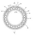
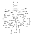
図1は本発明の一実施例によるエアレスタイヤを示す斜視図、図2は図1のエアレスタイヤを示す正面図、図3は図2に示したA部分の拡大図、図4は図2に示したIV−IV線に沿ってエアレスタイヤを切った断面図である。 1 is a perspective view showing an airless tire according to an embodiment of the present invention, FIG. 2 is a front view showing the airless tire of FIG. 1, FIG. 3 is an enlarged view of portion A shown in FIG. 2, and FIG. It is sectional drawing which cut the airless tire along the shown IV-IV line.
図1から図4に示すように、本実施例によるエアレスタイヤ1は、第1バンド40、第2バンド50、リム20、トレッド10、補強層30、スポーク61、第1連結部材62を含む。しかし、リム20、補強層30、及びトレッド10は省略してもよい。
As shown in FIGS. 1 to 4, the airless tire 1 according to the present embodiment includes a
第1バンド40と第2バンド50は所定の幅をもって両端部が連結されている帯状をなす。第1バンド40の外側には第2バンド50が間隔をおいて位置する。それによって第1バンド40の外部面と第2バンド50の内部面は互いに対向する。このような第1バンド40と第2バンド50は、玄武岩繊維、玄武岩繊維に基づいた短繊維、及びこれらの組み合わせからなる群から選択される何れか1つを用いてもよい。
The
玄武岩繊維は、溶岩が火山作用によって地表に噴出して形成された細粒質の岩石である玄武岩から取り出された天然繊維である。玄武岩繊維は、優れた機械的物性を有するため、ポリマー複合材料の補強繊維、コンクリート構造物の補修補強繊維などにも用いられる。 Basalt fiber is a natural fiber extracted from basalt, a fine-grained rock formed by lava erupting to the surface by volcanic action. Basalt fibers have excellent mechanical properties, and are used for reinforcing fibers for polymer composite materials, repair reinforcing fibers for concrete structures, and the like.
一方、第1バンド40の内側面には、車両のハブドラム(図示せず)に連結されるリム20が結合される。そして、第2バンド50の外側面には、地面に接して車両の調整性を有するトレッド10が結合される。
On the other hand, a
補強層30は第2バンド50とトレッド10との間に位置する。補強層30は、タイヤの空気層であり、車両の荷重を支える役割をする。
The reinforcing
すなわち、前記補強層30によって車両の荷重が円滑に支持される。
That is, the vehicle load is smoothly supported by the reinforcing
補強層30は、鋼線、スチールベルト、繊維コード、複合材料(composite)、中空(hollow)構造のチューブ、及びこれらの組み合わせからなる群から選択される何れか1つを用いてもよい。
The reinforcing
また、補強層30は、玄武岩繊維、玄武岩繊維に基づいた短繊維、及びこれらの組み合わせからなる群から選択される何れか1つを用いてもよい。
The reinforcing
さらに、複合材料(composite)は、樹脂(resin)とガラス繊維(glass fiber)などを混合した複合材料であることが好ましい。 Further, the composite material is preferably a composite material in which a resin and glass fiber are mixed.
そして、中空(hollow)構造のチューブは、複合材料の繊維形態ではなく、チューブ形態である。 And the tube of a hollow structure is not a fiber form of a composite material but a tube form.
スポーク61は第1バンド40と第2バンド50との間に位置する。スポーク61は第1バンド40と第2バンド50が間隔をおいて離れているように支持台の役割をする。スポーク61は第1バンド40と第2バンド50に沿って間隔をおいて配列される。スポーク61は第1部材61a及び第2部材61bを含む。
The
第1部材61aは第1バンド40の外部面から第2バンド50側に突出している。第1部材61aの一側61a1は第1バンド40に連結され、他側61a2は第2バンド50の内部面から間隔をおいて離れている。このような第1部材61aは第1バンド40の外部面に沿って間隔をおいて形成される。突出している第1部材61aは所定の長さをもって曲線形態で曲がっている。曲線形態で曲がっている第1部材61aは、隣り合う第1部材61aとは反対方向に曲がっている。それによって、第1部材61aの他側61a2は間隔をおいて対向している。隣り合う第1部材61aの他側61a2の間隔は一側61a1の間隔よりも狭い。
The
前記第1部材の曲率半径(R1)は40mm以上50mm未満であり、前記第2部材の曲率半径(R2)は30mm以上40mm未満であることが好ましい。 The curvature radius (R1) of the first member is preferably 40 mm or more and less than 50 mm, and the curvature radius (R2) of the second member is preferably 30 mm or more and less than 40 mm.
前記第1部材61aの曲率半径(R1)が40mm未満の場合と、前記第2部材61bの曲率半径(R1)が30mm未満の場合は、部品間の干渉によって耐疲労性に劣り、屈曲性が増加することになる。
When the radius of curvature (R1) of the
第2部材61bは第1部材61aと同一線上に位置し、第2バンド50の内部面から第1バンド40側に突出している。第2部材61bは第2バンド50の内部面に沿って間隔をおいて形成される。第2部材61bの一側61b1は第2バンド50に連結され、他側61b2は第1バンド40の外部面から間隔をおいて離れている。突出している第2部材61bは所定の長さをもって曲線形態で曲がっている。第2部材61bの長さが第1部材61aの長さよりも長く形成される。曲線形態で曲がっている第2部材61bは、隣り合う第2部材61bとは反対方向に曲がっている。それによって、第2部材61bの他側61b2は間隔をおいて対向している。隣り合う第2部材61bの他側61b2の間隔は一側61b1の間隔よりも狭い。さらに、隣り合う第2部材61bの一側61b1間の間隔は、第1部材61aの隣り合う一側61a1間の間隔よりも広く形成される。
The
このような第2部材61bの他側61b2は、第1部材61aの他側61a2に連結される。互いに連結された第1部材61aと第2部材61bの曲線方向は互いに反対方向となる。前記第2部材の曲率半径(R2)は30mm以上40mm未満であることが好ましい。
The other side 61b2 of the
一方、図4に示すように、突出している第2部材61bは第2バンド50から遠くなるほど(H2)他側61b2の両側の間隔が近づくようになる。
On the other hand, as shown in FIG. 4, the protruding
このようなスポーク61において、地面に接するトレッド10と隣り合うスポーク61はその曲線形態が変形されて曲がることがある。そして、変形されたスポーク61は、トレッド10が地面から離れると、元の状態に戻る。
In such a
第1連結部材62及び第2連結部材70は、隣り合うスポーク61を互いに連結して1つのスポークセル60を形成する。このようなスポークセル60は第1バンド40と第2バンド50との間に22〜26個が形成される。
The first connecting
このように22〜26個のスポークセルが形成されると、金型の製造工程に有利であり、耐疲労性の向上と振動の分散が円滑になる利点が得られる。 When 22 to 26 spoke cells are formed in this way, it is advantageous for the mold manufacturing process, and the advantage of improving fatigue resistance and smoothing the vibration is obtained.
スポークセルの個数が22個未満の場合、振動による荷重伝達力が低下する問題がある。 When the number of spoke cells is less than 22, there is a problem that load transmission force due to vibration is reduced.
また、スポークセルの個数が26個を超え、その個数が多くなるほど剛性が増大して乗り心地が低減する虞がある。 In addition, the number of spoke cells exceeds 26, and as the number increases, the rigidity may increase and the ride comfort may decrease.
第1連結部材62は、隣り合うスポーク61の間に位置するが、第1部材61aと第2部材61bが互いに連結されている部分に位置し、隣り合うスポーク61を互いに連結する。
Although the
一方、隣り合うスポーク61を連結する第1連結部材62と、隣り合うスポークセル60を連結する第2連結部材70は、ジグザグ状に配置されてスポーク61とスポークセル60を連結する。第1連結部材62と第2連結部材70がジグザグ状に連結されることにより、スポーク61の変形が自由にできる。
On the other hand, the first connecting
第2連結部材70は、隣り合うスポークセル60の間に位置する。第2連結部材70は第2部材61bを互いに連結する。第2連結部材70の長さは第1連結部材62の長さよりも長く形成される。
The second connecting
隣り合うスポーク61を第1連結部材62が互いに連結して1つのスポークセル60を形成し、第2連結部材70が隣り合うスポークセル60を連結することにより、第1バンド40と第2バンド50との間には複数の空間が形成される。
The first connecting
図3を参照して図6を説明すると、トレッド10が地面に接してドラムと垂直をなすと、トレッド10に垂直荷重が加えられる。この際、第1バンド40と第2バンド50の間隔が狭まる。間隔の狭まった第1バンド40と第2バンド50との間に位置した隣り合うスポーク61は、曲率半径が小さくなって互いに対向する方向に変形して距離(L1)が狭まる。すなわち、第1部材61aと第2部材61bの曲線構造によって、第1部材61aと第2部材61bが連結された部分の隣り合うスポーク61の間隔が狭まる。距離(L1)が狭まることにより第1連結部材62は圧縮される。そして、第1連結部材62は第2バンド50に近接するようになる。変形された隣り合うスポーク61は、圧縮された第1連結部材62によって互いに干渉することはない。さらに、隣り合うスポーク61の間隔が狭まることにより、隣り合うスポークセル60の第2部材61bの間隔は遠くなる。
6 will be described with reference to FIG. 3. When the
具体的には、第1部材61aと第2部材61bが互いに連結されて形成された隣り合うスポーク61が互いに近づく方向に変形される場合、空気圧タイヤの屈伸運動形態を有するスポーク61が変形して車両の調整性及び乗り心地を向上させる。
Specifically, when the
言い換えれば、このような構造のエアレスタイヤ1は、地面に接したトレッド10と隣り合うスポーク61はその間隔が狭まるように変形される。この際、隣り合うスポーク61は、第1連結部材62によって互いに干渉することはない。そして、隣り合うスポークセル60は、第2連結部材70によって互いに干渉することはない。隣り合うスポーク61、スポークセル60が互いに干渉しないため、騒音の発生を防止し、耐疲労性が向上する効果が得られる。
In other words, in the airless tire 1 having such a structure, the
トレッド10がドラムと垂直をなし、その後、地面から離れると、変形されたスポーク61はその弾性力によって元の状態に戻る。ドラムとトレッド10が垂直をなす場合に加えられた荷重からタイヤが過度に圧縮されることはないため、タイヤの本来の機能を完全に行うことができる。
When the
本発明のエアレスタイヤ1は、曲線を有するスポーク61を連結することにより形成されたスポークセル60が第1バンド40と第2バンド50との間に位置することで、釣り合いの取れた構造的剛性が得られ、スポーク61とスポークセル60が第1連結部材62と第2連結部材70により連結されて車両の荷重を支え、地面と接触面が均一になる。また、曲線のスポーク61が変形されるため、ストレスを分散させてスポークの耐久性及び運転者に伝達される路面衝撃の吸収性が向上される。
In the airless tire 1 of the present invention, the
このようなエアレスタイヤ1は、第1バンド40と第2バンド50との間にこれらを支持するスポークセル60が位置し、スポーク61とスポークセル60を第1連結部材62と第2連結部材70が互いに連結するため、釣り合いの取れた構造的剛性により圧縮力及び引張力を両方とも実現することができる。また、スポーク61の変形によりストレスの分散性が改善される。それによって、スポーク構造の耐疲労性が向上される。
In the airless tire 1, the
エアレスタイヤ1に関する静特性の評価結果(図5参照)に示すように、膨張物質(Auxetic materials)(A表示部)により形成される従来のスポークに比べて、本発明による曲線をもって第1連結部材62と第2連結部材70により連結されたスポーク61とスポークセル60の構造を有するエアレスタイヤ(B表示部)の静特性が向上したことが分かる。
As shown in the evaluation results of static characteristics of the airless tire 1 (see FIG. 5), the first connecting member has a curve according to the present invention as compared with a conventional spoke formed of an auxetic material (A display portion). It can be seen that the static characteristics of the airless tire (B display portion) having the structure of the
結果的に、エアレスタイヤ(B表示部)は衝撃吸収率が高いながらも、静的荷重に対する耐力が高いことが分かる。 As a result, it can be seen that the airless tire (B display portion) has a high impact resistance, but has a high proof strength against static loads.
図3を参照して図6に示すように、突出した第1部材61aが第1バンド40から遠ざかるほど他側61a2の両側間隔が近づき、突出した第2部材61bが第2バンド50から遠ざかるほど他側61b2の両側間隔が近づいてスポーク61の変形率が向上する。空気圧タイヤの性能に一番大切な空気圧を使用しなくてもタイヤとしての機能を行うことができる。すなわち、隣り合うスポーク61どうしの干渉を回避して空気圧タイヤによる接地とほぼ同様の接地が得られる。
As shown in FIG. 6 with reference to FIG. 3, the distance between the opposite sides of the
言い換えれば、本発明のエアレスタイヤ1は、スポーク61の釣り合いの取れた構造的剛性により車両の荷重を十分に支えることができる。また、圧縮力と引張力を両方とも実現することができるため、ストレスの分散性を改善してスポーク構造の耐疲労性が向上する。そして、振動を分散することにより、地面から自動車のハブを介して運転者に及ぼす振動に対する吸収力が向上して良好な乗り心地を提供することができる。したがって、非空気入りタイヤの耐久性の向上だけでなく、車両の操縦性を向上させ、路面からの衝撃をよく分散させることにより、耐久性の改善と共に操縦性と車両の乗り心地の向上を図ることができる。
In other words, the airless tire 1 of the present invention can sufficiently support the load of the vehicle due to the balanced structural rigidity of the
上述した説明と図面では、スポーク61の形状を曲線形態にして曲がった構造としたが、本発明はスポーク61の形状をこのように限らず、地面に接したトレッド10に位置したスポーク61が荷重により自由に変形される構造であれば足りる。
In the above description and drawings, the shape of the
以上、本発明の望ましい実施例について詳細に説明したが、本発明の権利範囲はこの実施例により限定されることはなく、次の請求範囲で定義する本発明の基本概念を用いた当業者の様々な変形及び改良形態も本発明の権利範囲に属する。 The preferred embodiments of the present invention have been described in detail above, but the scope of the present invention is not limited by these embodiments, and those skilled in the art using the basic concept of the present invention defined in the following claims. Various modifications and improvements are also within the scope of the present invention.
1 エアレスタイヤ
10 トレッド
20 リム
30 補強層
40 第1バンド
50 第2バンド
60 スポークセル
61 スポーク
61a 第1部材
61b 第2部材
62 第1連結部材
70 第2連結部材
DESCRIPTION OF SYMBOLS 1
Claims (9)
前記第1バンドを離隔状態で囲み、前記第1バンドよりも大きな直径を有する第2バンドと、
前記第1バンドと第2バンドを連結し、前記第1バンドと前記第2バンドとの間に複数個が配置されるスポークと、
並んで配置される前記スポークを相互連結し、前記スポークに加えられた荷重を分散させる第1連結部材及び第2連結部材と、を含み、
前記第1連結部材及び前記第2連結部材は、互いにジグザグ状に配置され、前記スポークは、前記第1バンドから前記第2バンドの方へ曲線状に突出する第1部材と、前記第1部材と前記第2バンドを連結するように形成されて、前記前記第1部材の前記曲線状とは反対向きの曲線状に形成される第2部材を含むことを特徴とするエアレスタイヤ。 A circular first band;
A second band surrounding the first band in a separated state and having a larger diameter than the first band;
And spokes plurality is disposed between the first and second bands are connected, said first band and said second band,
A first connecting member and a second connecting member that interconnect the spokes arranged side by side and distribute a load applied to the spoke; and
The first connecting member and the second connecting member are arranged in a zigzag shape, and the spoke protrudes from the first band toward the second band in a curved shape, and the first member An airless tire comprising a second member formed so as to connect the second band and having a curved shape opposite to the curved shape of the first member.
前記第2バンドと前記トレッドとの間に位置した補強層と、
をさらに含むことを特徴とする請求項1に記載のエアレスタイヤ。 A tread coupled to the outer surface of the second band;
A reinforcing layer positioned between the second band and the tread;
The airless tire according to claim 1, further comprising:
The airless tire according to claim 1, wherein the length of the second member is longer than the length of the first member.
Applications Claiming Priority (2)
| Application Number | Priority Date | Filing Date | Title |
|---|---|---|---|
| KR10-2012-0069416 | 2012-06-27 | ||
| KR1020120069416A KR101378436B1 (en) | 2012-06-27 | 2012-06-27 | Airless tire |
Publications (2)
| Publication Number | Publication Date |
|---|---|
| JP2014008958A JP2014008958A (en) | 2014-01-20 |
| JP5588046B2 true JP5588046B2 (en) | 2014-09-10 |
Family
ID=48470795
Family Applications (1)
| Application Number | Title | Priority Date | Filing Date |
|---|---|---|---|
| JP2013109813A Active JP5588046B2 (en) | 2012-06-27 | 2013-05-24 | Airless tire |
Country Status (5)
| Country | Link |
|---|---|
| US (1) | US9387726B2 (en) |
| EP (1) | EP2679406B1 (en) |
| JP (1) | JP5588046B2 (en) |
| KR (1) | KR101378436B1 (en) |
| CN (1) | CN103507571B (en) |
Families Citing this family (66)
| Publication number | Priority date | Publication date | Assignee | Title |
|---|---|---|---|---|
| KR101378436B1 (en) * | 2012-06-27 | 2014-03-27 | 한국타이어 주식회사 | Airless tire |
| FR2997385B1 (en) * | 2012-10-26 | 2014-11-28 | Thales Sa | MOTORIZATION SYSTEM FOR ARTICULATION WITH FLEXIBLE BEARING RUNWAYS |
| US9242509B2 (en) * | 2013-02-07 | 2016-01-26 | Alice Chang | Non pneumatic vehicle tires and pneumatic vehicle tires with tread patterns |
| KR101356326B1 (en) * | 2013-02-28 | 2014-01-29 | 한국타이어 주식회사 | Non-pneumatic tire having reinforcing material of plate wire structure |
| USD731962S1 (en) * | 2013-03-15 | 2015-06-16 | Caterpillar Inc. | Surface pattern for a tire |
| JP6159138B2 (en) * | 2013-05-07 | 2017-07-05 | 住友ゴム工業株式会社 | Airless tire |
| EP3007909A4 (en) | 2013-06-15 | 2017-03-01 | Ronald Thompson | Annular ring and non-pneumatic tire |
| US9283806B2 (en) * | 2014-01-22 | 2016-03-15 | Lindsay Corporation | Wheel assembly for an irrigation system |
| JP6097265B2 (en) * | 2014-10-02 | 2017-03-15 | 住友ゴム工業株式会社 | Airless tire |
| USD777655S1 (en) | 2014-12-02 | 2017-01-31 | Caterpillar Inc. | Urethane tire |
| WO2016100017A1 (en) * | 2014-12-18 | 2016-06-23 | Bridgestone Americas Tire Operations, Llc | Tire with arched spokes |
| USD792332S1 (en) | 2015-06-03 | 2017-07-18 | Mtd Products Inc | Non-pneumatic tire |
| US20160214435A1 (en) | 2015-01-27 | 2016-07-28 | Mtd Products Inc | Wheel assemblies with non-pneumatic tires |
| US10899169B2 (en) | 2015-01-27 | 2021-01-26 | Mtd Products Inc | Wheel assemblies with non-pneumatic tires |
| CN104626884B (en) * | 2015-02-03 | 2017-03-15 | 青岛科技大学 | A kind of on-inflatable safety tread |
| CA2976055A1 (en) | 2015-02-04 | 2016-08-11 | Advancing Mobility, Llc. | Non-pneumatic tire and other annular devices |
| USD767483S1 (en) | 2015-02-13 | 2016-09-27 | Caterpillar Inc. | Tire tread |
| EP3064371B1 (en) * | 2015-03-05 | 2020-04-29 | Sumitomo Rubber Industries, Ltd. | Airless tire |
| KR101714401B1 (en) | 2015-04-13 | 2017-03-09 | 인에이블 주식회사 | Airless tire |
| USD784917S1 (en) | 2015-06-03 | 2017-04-25 | Mtd Products Inc | Non-pneumatic tire |
| USD773387S1 (en) * | 2015-07-10 | 2016-12-06 | Caterpillar Inc. | Tire shear band |
| KR101584340B1 (en) * | 2015-09-25 | 2016-01-13 | 주식회사 코휠 | Non-pneumatic wheels and manufacturing method |
| JP1556887S (en) * | 2015-10-08 | 2016-08-22 | ||
| CN108136835B (en) * | 2015-10-09 | 2019-11-22 | 株式会社普利司通 | Non-inflatable tyre |
| JP6577824B2 (en) * | 2015-10-26 | 2019-09-18 | 住友ゴム工業株式会社 | Airless tire |
| US10696096B2 (en) * | 2015-12-08 | 2020-06-30 | The Goodyear Tire & Rubber Company | Non-pneumatic tire |
| US20170174005A1 (en) * | 2015-12-21 | 2017-06-22 | The Goodyear Tire & Rubber Company | Non-pneumatic tire with parabolic disks |
| KR102409373B1 (en) | 2015-12-23 | 2022-06-15 | 삼성전자주식회사 | Robot cleaner |
| EP3397468B1 (en) | 2015-12-29 | 2021-05-05 | Bridgestone Americas Tire Operations, LLC | Tire with shaped tread |
| US11052706B2 (en) | 2015-12-29 | 2021-07-06 | Bridgestone Americas Tire Operations, Llc | Composite layer tire |
| EP3397467B1 (en) | 2015-12-29 | 2021-04-14 | Bridgestone Americas Tire Operations, LLC | Tire with variable shear element |
| USD826144S1 (en) * | 2016-06-14 | 2018-08-21 | Sumitomo Rubber Industries, Ltd. | Tire for automobile |
| US10010741B2 (en) | 2016-07-28 | 2018-07-03 | Sound Shore Innovations L.L.C. | Quiet bumper plate |
| AU201711183S (en) | 2016-09-02 | 2017-03-15 | Razor Usa Llc | Airless tire |
| CN109803837A (en) * | 2016-09-02 | 2019-05-24 | 美国锐哲有限公司 | Air-free tyre |
| EP3519204B1 (en) * | 2016-10-03 | 2020-07-29 | Compagnie Générale des Etablissements Michelin | Reinforced rubber spoke for a tire |
| USD832770S1 (en) * | 2016-10-28 | 2018-11-06 | Bridgestone Corporation | Non-pneumatic tire |
| JP1576394S (en) * | 2016-10-28 | 2017-05-15 | ||
| JP1579281S (en) * | 2016-10-28 | 2017-06-19 | ||
| US10040317B2 (en) * | 2016-11-15 | 2018-08-07 | The Goodyear Tire & Rubber Company | Non-pneumatic support structure |
| EP3339055B1 (en) * | 2016-12-21 | 2020-03-04 | Bridgestone Americas Tire Operations, LLC | Tire with tensioned spokes |
| CN110198846B (en) * | 2016-12-22 | 2022-08-30 | 米其林集团总公司 | Method of mounting a non-pneumatic tire on a wheel hub |
| EP3558695B1 (en) * | 2016-12-22 | 2021-02-03 | Compagnie Générale des Etablissements Michelin | Non-pneumatic wheel and method of mounting non-pneumatic tire |
| US10953695B1 (en) * | 2017-02-23 | 2021-03-23 | Koby Keyes Product Design, LLC | Light-weight walker |
| US10639226B1 (en) * | 2017-02-23 | 2020-05-05 | Koby Keyes Product Design, LLC | Mobility assistance apparatus |
| US10286725B2 (en) | 2017-03-22 | 2019-05-14 | The Goodyear Tire & Rubber Company | Non-pneumatic support structure |
| FR3067285B1 (en) * | 2017-06-09 | 2022-01-07 | Michelin & Cie | MOUNTING WHEEL FOR MOTOR VEHICLE AND MOUNTED ASSEMBLY COMPRISING SUCH MOUNTING WHEEL |
| US11179969B2 (en) | 2017-06-15 | 2021-11-23 | Camso Inc. | Wheel comprising a non-pneumatic tire |
| KR102005417B1 (en) * | 2017-09-11 | 2019-07-30 | 금호타이어 주식회사 | Rim for non pneumatic tire and wheel including the same |
| CN111183045A (en) * | 2017-10-10 | 2020-05-19 | 普利司通美国轮胎运营有限责任公司 | Non-pneumatic tire with variable thickness web |
| CA181459S (en) | 2017-11-24 | 2019-04-01 | Michelin & Cie | Pneumatic tyre |
| JP6989082B2 (en) | 2017-12-14 | 2022-01-05 | ブリヂストン アメリカズ タイヤ オペレーションズ、 エルエルシー | Non-pneumatic tire with multi-piece web |
| CN108382133B (en) * | 2018-04-28 | 2023-07-18 | 无锡职业技术学院 | Non-pneumatic tire and disassembly and assembly method thereof |
| CN109591518B (en) * | 2018-12-29 | 2020-04-17 | 燕山大学 | Flower structure type inflation-free tyre |
| CN113226799A (en) * | 2019-01-04 | 2021-08-06 | 普利司通美国轮胎运营有限责任公司 | Tire tread with belt layer |
| USD883913S1 (en) * | 2019-02-28 | 2020-05-12 | The Goodyear Tire & Rubber Company | Tire |
| US11273673B2 (en) | 2019-10-25 | 2022-03-15 | The Goodyear Tire & Rubber Company | Modular non-pneumatic support structure |
| TWI716174B (en) | 2019-10-31 | 2021-01-11 | 建大工業股份有限公司 | Non-pneumatic tire |
| US11142022B2 (en) | 2019-11-15 | 2021-10-12 | The Goodyear Tire & Rubber Company | Support structure |
| US11318791B2 (en) | 2019-11-15 | 2022-05-03 | The Goodyear Tire & Rubber Company | Wheel for a support structure |
| US11124024B2 (en) | 2019-11-25 | 2021-09-21 | The Goodyear Tire & Rubber Company | Support structure |
| CA199606S (en) | 2020-06-03 | 2022-06-10 | Michelin & Cie | Tire |
| KR102415200B1 (en) * | 2020-09-01 | 2022-07-01 | 금호타이어 주식회사 | Non pneumatic tire |
| KR102437390B1 (en) * | 2020-11-16 | 2022-08-29 | 진성알엔디(주) | Non-pneumatic tire |
| CN113246661B (en) * | 2021-06-25 | 2022-04-26 | 季华实验室 | Support body, elastic support assembly and tire |
| USD1008161S1 (en) * | 2021-10-07 | 2023-12-19 | Hankook Tire & Technology Co., Ltd. | Non-pneumatic tire |
Family Cites Families (31)
| Publication number | Priority date | Publication date | Assignee | Title |
|---|---|---|---|---|
| FR2652310A1 (en) * | 1989-09-28 | 1991-03-29 | Michelin & Cie | NON-PNEUMATIC DEFORMABLE BANDAGE. |
| KR950008368B1 (en) * | 1992-05-07 | 1995-07-28 | 주식회사금호 | Non-pneumatic tire |
| US7108331B2 (en) * | 2000-02-28 | 2006-09-19 | Myron Stuart Hurwitz | Generation of in-line skates and skate-boards with safety “EDGING FRICTION CONTROL™” |
| US6615885B1 (en) * | 2000-10-31 | 2003-09-09 | Irobot Corporation | Resilient wheel structure |
| KR100810935B1 (en) | 2001-08-24 | 2008-03-10 | 소시에떼 드 테크놀로지 미쉐린 | Non-pneumatic tire |
| FR2895936B1 (en) * | 2006-01-12 | 2010-06-04 | Michelin Soc Tech | CARRIER STRUCTURE FOR SUPPORT SUPPORT AND OPTIMIZED SUPPORT SUPPORT |
| WO2007137858A2 (en) * | 2006-05-31 | 2007-12-06 | Terramark Markencreation Gmbh | Airless tire for vehicles |
| JP3923073B1 (en) | 2006-10-27 | 2007-05-30 | 横浜ゴム株式会社 | Non-pneumatic tire |
| US8109308B2 (en) * | 2007-03-27 | 2012-02-07 | Resilient Technologies LLC. | Tension-based non-pneumatic tire |
| US8104524B2 (en) * | 2007-03-27 | 2012-01-31 | Resilient Technologies Llc | Tension-based non-pneumatic tire |
| ATE546300T1 (en) * | 2007-04-24 | 2012-03-15 | Yokohama Rubber Co Ltd | SOLID TIRE AND MANUFACTURING PROCESS THEREOF |
| JP2008303333A (en) * | 2007-06-08 | 2008-12-18 | Sumitomo Rubber Ind Ltd | Rubber composition, and tire with cap tread using the same |
| WO2009016962A1 (en) * | 2007-07-31 | 2009-02-05 | Toyo Tire & Rubber Co., Ltd. | Non-pneumatic tire, and its manufacturing method |
| US20090173421A1 (en) * | 2008-01-08 | 2009-07-09 | Freudenberg-Nok General Partnership | Flatless Hybrid Isolated Tire |
| JP4506853B2 (en) * | 2008-02-25 | 2010-07-21 | 横浜ゴム株式会社 | Non-pneumatic tire |
| US9108470B2 (en) * | 2008-09-29 | 2015-08-18 | Polaris Industries Inc. | Run-flat device |
| JP5221306B2 (en) * | 2008-11-28 | 2013-06-26 | 東洋ゴム工業株式会社 | Non-pneumatic tire |
| JP4674253B2 (en) * | 2008-11-28 | 2011-04-20 | 東洋ゴム工業株式会社 | Non-pneumatic tire |
| US8176957B2 (en) * | 2009-07-20 | 2012-05-15 | Resilient Technologies, Llc. | Tension-based non-pneumatic tire |
| US8944125B2 (en) * | 2009-07-20 | 2015-02-03 | Polaris Industries Inc. | Tension-based non-pneumatic tire |
| JP5314621B2 (en) * | 2010-03-02 | 2013-10-16 | 東洋ゴム工業株式会社 | Non-pneumatic tire |
| KR101043001B1 (en) * | 2010-09-14 | 2011-06-21 | 한국타이어 주식회사 | Airless tire |
| KR101301578B1 (en) * | 2010-12-08 | 2013-08-29 | 한국타이어 주식회사 | Non-pneumatic tire |
| KR101191923B1 (en) * | 2010-12-13 | 2012-10-17 | 한국타이어월드와이드 주식회사 | Spoke design method of non pneumatic tire |
| US20120234444A1 (en) * | 2011-03-18 | 2012-09-20 | Chemtura Corporation | Non-pneumatic tire with annular spoke reinforcing web |
| US9573422B2 (en) * | 2012-03-15 | 2017-02-21 | Polaris Industries Inc. | Non-pneumatic tire |
| US9290045B2 (en) * | 2012-04-05 | 2016-03-22 | Compagnie Generale Des Etablissements Michelin | Spoke for a tire with optimized thickness for improved durability |
| KR101378436B1 (en) * | 2012-06-27 | 2014-03-27 | 한국타이어 주식회사 | Airless tire |
| US9266388B2 (en) * | 2012-09-27 | 2016-02-23 | Mtd Products Inc | Non-pneumatic tire |
| KR101356326B1 (en) * | 2013-02-28 | 2014-01-29 | 한국타이어 주식회사 | Non-pneumatic tire having reinforcing material of plate wire structure |
| KR101411103B1 (en) * | 2013-11-06 | 2014-06-27 | 한국타이어 주식회사 | Non-pneumatic tire |
-
2012
- 2012-06-27 KR KR1020120069416A patent/KR101378436B1/en active IP Right Grant
-
2013
- 2013-05-22 EP EP13168820.2A patent/EP2679406B1/en active Active
- 2013-05-24 JP JP2013109813A patent/JP5588046B2/en active Active
- 2013-06-19 US US13/922,218 patent/US9387726B2/en active Active
- 2013-06-27 CN CN201310262882.4A patent/CN103507571B/en active Active
Also Published As
| Publication number | Publication date |
|---|---|
| CN103507571A (en) | 2014-01-15 |
| US9387726B2 (en) | 2016-07-12 |
| EP2679406B1 (en) | 2015-04-01 |
| US20140000777A1 (en) | 2014-01-02 |
| JP2014008958A (en) | 2014-01-20 |
| EP2679406A1 (en) | 2014-01-01 |
| KR20140001048A (en) | 2014-01-06 |
| CN103507571B (en) | 2016-06-01 |
| KR101378436B1 (en) | 2014-03-27 |
Similar Documents
| Publication | Publication Date | Title |
|---|---|---|
| JP5588046B2 (en) | Airless tire | |
| US20210188008A1 (en) | Non-pneumatic tire and other annular devices | |
| KR101362120B1 (en) | Airless tire | |
| US20190054767A1 (en) | Shear Band with Interlaced Reinforcements | |
| KR100967531B1 (en) | Non-pneumatic tire | |
| US8714217B2 (en) | Non-pneumatic wheel assembly and wheel, suspension and tire used therein | |
| JP4946011B2 (en) | Non-pneumatic tire | |
| US11167593B2 (en) | Reinforcement structure for non-pneumatic wheel | |
| JP5808048B2 (en) | Non-pneumatic tire | |
| KR20160088939A (en) | Airless tire construction having variable stiffness | |
| KR20120070469A (en) | Non pneumatic tire | |
| WO2008050503A1 (en) | Non-pneumatic tire | |
| KR101339821B1 (en) | Non pneumatic tire | |
| JP5921364B2 (en) | Non-pneumatic tire | |
| JP2018508403A (en) | Tire type equipment for vehicles | |
| US11298979B2 (en) | Non-pneumatic tire | |
| CN101830151B (en) | Non-pneumatic vehicle tire | |
| KR101301579B1 (en) | Non pneumatic tire | |
| KR20130037808A (en) | Non-pneumatic tire | |
| JP6092045B2 (en) | Non-pneumatic tire | |
| JP2014100932A (en) | Non-pneumatic tire | |
| EP3686032B1 (en) | A non-pneumatic tire | |
| KR101495100B1 (en) | Non pneumatic tire | |
| JP2013018427A (en) | Non-pneumatic tire | |
| KR20230019706A (en) | Non-pneumatic tire |
Legal Events
| Date | Code | Title | Description |
|---|---|---|---|
| A131 | Notification of reasons for refusal |
Free format text: JAPANESE INTERMEDIATE CODE: A131 Effective date: 20140304 |
|
| A521 | Request for written amendment filed |
Free format text: JAPANESE INTERMEDIATE CODE: A523 Effective date: 20140604 |
|
| TRDD | Decision of grant or rejection written | ||
| A01 | Written decision to grant a patent or to grant a registration (utility model) |
Free format text: JAPANESE INTERMEDIATE CODE: A01 Effective date: 20140701 |
|
| A61 | First payment of annual fees (during grant procedure) |
Free format text: JAPANESE INTERMEDIATE CODE: A61 Effective date: 20140724 |
|
| R150 | Certificate of patent or registration of utility model |
Ref document number: 5588046 Country of ref document: JP Free format text: JAPANESE INTERMEDIATE CODE: R150 |
|
| R250 | Receipt of annual fees |
Free format text: JAPANESE INTERMEDIATE CODE: R250 |
|
| R250 | Receipt of annual fees |
Free format text: JAPANESE INTERMEDIATE CODE: R250 |
|
| R250 | Receipt of annual fees |
Free format text: JAPANESE INTERMEDIATE CODE: R250 |
|
| R250 | Receipt of annual fees |
Free format text: JAPANESE INTERMEDIATE CODE: R250 |
|
| R250 | Receipt of annual fees |
Free format text: JAPANESE INTERMEDIATE CODE: R250 |
|
| R250 | Receipt of annual fees |
Free format text: JAPANESE INTERMEDIATE CODE: R250 |