JP5580858B2 - Chair-type massage device - Google Patents

Chair-type massage device Download PDF

Info

Publication number
JP5580858B2
JP5580858B2 JP2012195058A JP2012195058A JP5580858B2 JP 5580858 B2 JP5580858 B2 JP 5580858B2 JP 2012195058 A JP2012195058 A JP 2012195058A JP 2012195058 A JP2012195058 A JP 2012195058A JP 5580858 B2 JP5580858 B2 JP 5580858B2
Authority
JP
Japan
Prior art keywords
footrest
frame
leg rest
leg
chair
Prior art date
Legal status (The legal status is an assumption and is not a legal conclusion. Google has not performed a legal analysis and makes no representation as to the accuracy of the status listed.)
Active
Application number
JP2012195058A
Other languages
Japanese (ja)
Other versions
JP2012232202A (en
JP2012232202A5 (en
Inventor
愼一 小栗
光明 藤代
敏久 吉田
晃一 久保
仁 久富
Current Assignee (The listed assignees may be inaccurate. Google has not performed a legal analysis and makes no representation or warranty as to the accuracy of the list.)
Hitachi Maxell Energy Ltd
Original Assignee
Hitachi Maxell Energy Ltd
Priority date (The priority date is an assumption and is not a legal conclusion. Google has not performed a legal analysis and makes no representation as to the accuracy of the date listed.)
Filing date
Publication date
Application filed by Hitachi Maxell Energy Ltd filed Critical Hitachi Maxell Energy Ltd
Priority to JP2012195058A priority Critical patent/JP5580858B2/en
Publication of JP2012232202A publication Critical patent/JP2012232202A/en
Publication of JP2012232202A5 publication Critical patent/JP2012232202A5/ja
Application granted granted Critical
Publication of JP5580858B2 publication Critical patent/JP5580858B2/en
Active legal-status Critical Current
Anticipated expiration legal-status Critical

Links

Images

Landscapes

  • Special Chairs (AREA)
  • Massaging Devices (AREA)

Description

本発明は、座部の前側に下腿を支持する脚載部と足台とが設けてある椅子式のマッサージ装置に関する。   The present invention relates to a chair-type massage apparatus in which a leg rest and a footrest for supporting the lower leg are provided on the front side of a seat.

この種のマッサージ装置において、使用者の下腿の長さに応じて脚載部と足台を伸縮させることは、特許文献1および特許文献2に公知である。特許文献1のマッサージ装置では、脚載部を2個の脚保持部材で構成し、これらの脚保持部材と足台とを伸縮構造で伸縮可能としている。伸縮構造は、固定レールでスライド案内される可動レールと、可動レールを退入付勢するばねと、脚保持部材および足台を伸縮操作するリンク機構とで構成してある。2個の脚保持部材は固定レールに沿って転動変位でき、足台は可動レールの突端に固定してある。   In this type of massage device, it is known in Patent Document 1 and Patent Document 2 that the leg rest and the footrest are expanded and contracted according to the length of the user's lower leg. In the massage device of Patent Document 1, the leg rest is configured by two leg holding members, and these leg holding members and footrests can be extended and contracted by an elastic structure. The telescopic structure includes a movable rail that is slid and guided by a fixed rail, a spring that retreats and biases the movable rail, and a link mechanism that expands and contracts the leg holding member and the footrest. The two leg holding members can be rolled and displaced along the fixed rail, and the footrest is fixed to the protruding end of the movable rail.

特許文献2のマッサージ装置においては、座部と脚載部をスライド体で連結し、脚載部を座部に対してスライド伸縮可能としている。また、足台と脚載部とをスライド体で連結し、足台を脚載部に対してスライド伸縮可能としている。脚載部および足台は、それぞれ専用のばねで退縮する向きに移動付勢してある。   In the massage device of Patent Document 2, the seat and the leg rest are connected by a slide body, and the leg rest can be slidably extended with respect to the seat. Further, the footrest and the leg rest are connected by a slide body so that the foot rest can slide and extend with respect to the leg rest. The leg rest and the footrest are each urged to move in a retracting direction by a dedicated spring.

特開2004−8258号公報(段落番号0019、図6、図7)Japanese Unexamined Patent Publication No. 2004-8258 (paragraph number 0019, FIGS. 6 and 7) 特許第4009648号公報(段落番号0015〜0016、図7)Japanese Patent No. 4009648 (paragraph numbers 0015 to 0016, FIG. 7)

特許文献1のマッサージ装置によれば、使用者の下腿の長さに応じて脚保持部材と足台を伸縮変位できるが、使用者によっては各脚保持部材の変位位置を、ふくらはぎやくるぶしなどのマッサージしたい位置に適合できないことがある。これは、ふくらはぎやくるぶしの位置が下腿の長さに概ね比例することを前提にして、2個の脚保持部材を足台の伸長量に比例してリンク機構で伸長変位させるためである。特許文献2のマッサージ装置によれば、脚載部と足台を個別にスライド操作できるものの、足台の伸長動作に連動して脚載部をスライド変位させるので、必ずしも脚載部を好適な位置に変位できるとは限らず、この場合にも脚載部をマッサージしたい位置に適合できないことがある。   According to the massage device of Patent Document 1, the leg holding member and the footrest can be expanded and contracted according to the length of the user's lower leg, but depending on the user, the displacement position of each leg holding member can be changed to a calf or ankle. You may not be able to fit the position you want to massage. This is because the two leg holding members are extended and displaced by the link mechanism in proportion to the extension amount of the footrest on the assumption that the position of the calf and the ankle is substantially proportional to the length of the lower leg. According to the massage device of Patent Document 2, although the leg rest and the footrest can be individually slid, the leg rest is slid in conjunction with the extension operation of the footrest, so that the leg rest is not necessarily in a suitable position. In this case, the leg rest may not be adapted to the position where it is desired to be massaged.

本発明の目的は、足台を下腿の長さに応じて伸長変位させながら脚載部をマッサージしたい位置に適合して変位でき、したがって、下腿の個人差とは無関係に誰でもがふくらはぎ、くるぶし、足裏などのマッサージを好適に行なえる椅子式のマッサージ装置を提供することにある。   The object of the present invention is to allow the footrest to be displaced according to the position where the leg rest is desired to be massaged while extending and displacing the footrest according to the length of the lower leg. An object of the present invention is to provide a chair-type massage apparatus that can suitably perform massages such as soles.

本発明のマッサージ装置は、背もたれ4と座部2を有する椅子本体と、座部2の前側に配置される脚載部5と、脚載部5を支持するべース枠27と、脚載部5の下端に配置される足台6と、脚載部5と足台6のそれぞれに設けられるマッサージ体20・24を備えている。椅子本体に支持される脚載部5のフレーム18とベース枠27との間に設けられて、該脚載部5を伸長待機位置と伸長位置との間で伸縮操作する第1伸縮機構と、足台6の台枠22とベース枠27との間に設けられて、該足台6を伸長待機位置と伸長位置との間で伸縮操作する第2伸縮機構とを備え、これら第1伸縮機構と第2伸縮機構により、該脚載部5と該足台6とが、独立して伸縮変位できるように構成されている。台枠22を移動付勢することにより、足台6を伸長待機位置へ向って復帰操作可能にするばね61が、台枠22を構成して垂直に延びるスライド軸62の内部に収容されている。そして、ばね61が、引っ張りばねで形成されており、その下端が台枠22に掛止され、上端が脚載部5のフレーム18に掛止されていることを特徴とする。 The massage device of the present invention includes a chair body having a backrest 4 and a seat portion 2, a leg rest portion 5 disposed on the front side of the seat portion 2, a base frame 27 that supports the leg rest portion 5, and a leg rest. A footrest 6 disposed at the lower end of the portion 5 and massage bodies 20 and 24 provided on the leg rest portion 5 and the footrest 6 are provided. A first telescopic mechanism provided between the frame 18 of the leg rest 5 supported by the chair body and the base frame 27, and extending and contracting the leg rest 5 between the extension standby position and the extension position; A first telescopic mechanism provided between the base frame 22 and the base frame 27 of the footrest 6 for operating the footrest 6 between the stretch standby position and the stretch position. And the leg mounting part 5 and the footrest 6 are configured such that they can be expanded and contracted independently by the second expansion / contraction mechanism. A spring 61 that enables the footrest 6 to return to the extension standby position by moving and biasing the frame 22 is housed inside a slide shaft 62 that constitutes the frame 22 and extends vertically. . And the spring 61 is formed with the tension spring, The lower end is latched by the base frame 22, The upper end is latched by the flame | frame 18 of the leg mounting part 5, It is characterized by the above-mentioned.

足台6が、足裏が当接可能に構成されており、使用者が座部2に着座した状態で足台6を踏み出して操作することにより、使用者の下腿の長さに応じて足台6を伸長変位することができるように構成されている。The footrest 6 is configured such that the soles can come into contact with each other, and when the user steps on the footrest 6 while sitting on the seat 2, the foot can be adjusted according to the length of the user's lower leg. It is comprised so that the base 6 can be extendedly displaced.

前記第1伸縮機構が電動式である。The first telescopic mechanism is an electric type.

スライド軸62は、左右一対設けられており、ばね61が、左右一対のスライド軸62の各々の内部に収容されている。 A pair of left and right slide shafts 62 are provided, and a spring 61 is accommodated inside each of the pair of left and right slide shafts 62.

本発明のマッサージ装置では、脚載部5と、脚載部5の下端に配置される足台6とを備えるものとした。また、本発明のマッサージ装置では、足台6の台枠22を、スライド軸62により伸長待機位置と伸長位置との間で伸縮可能な構成とした。これによれば、脚載部5の下端に配置される足台6の台枠22を、脚載部5に対して個別に伸縮させることができるので、下腿における「ふくらはぎ」や「くるぶし」の位置の個人差に対応しながら、脚載部5の位置を自由に変更してマッサージを行なうことができ、ふくらはぎ、あるいはくるぶしなどのマッサージを誰もが好適に行なえる。また、使用者は足台6を伸長させたのち、足台6の位置を基準にして脚載部5を変位させて、ふくらはぎの任意の部分をマッサージでき、従来のマッサージ装置に比べて、脚載部5によるマッサージ位置の自由度を拡大できる。 In the massage device of the present invention, the leg rest 5 and the footrest 6 disposed at the lower end of the leg rest 5 are provided. In the massage device of the present invention, the frame 22 of the footrest 6 is configured to be extendable between the extension standby position and the extension position by the slide shaft 62. According to this, since the base frame 22 of the footrest 6 arranged at the lower end of the leg rest part 5 can be individually expanded and contracted with respect to the leg rest part 5, "calf" and "ankle" in the lower leg While responding to individual differences in position, the position of the leg rest portion 5 can be freely changed to perform massage, and anyone can perform massage such as calf or ankle. In addition, the user can extend the footrest 6 and then move the leg rest 5 with reference to the position of the footrest 6 to massage any part of the calf. The degree of freedom of the massage position by the mounting part 5 can be expanded.

足台6が、足裏が当接可能に構成されており、使用者が座部2に着座した状態で足台6を踏み出して操作することにより、使用者の下腿の長さに応じて足台6を伸長変位することができるように構成されていると、足台6で足を受け止めた状態において、足載部5の位置を変位させて、ばね61の張力の変化に見合う力を足裏に作用させることができる。つまり、足載部5の位置を変位することによって、足裏に作用する力を大小に変更して、使用者の好みに適合した力を足裏に作用させることができる。The footrest 6 is configured such that the soles can come into contact with each other, and when the user steps on the footrest 6 while sitting on the seat 2, the foot can be adjusted according to the length of the user's lower leg. If the base 6 is configured to be able to extend and displace, the position of the footrest portion 5 is displaced in a state where the foot is received by the footrest 6, and a force commensurate with the change in tension of the spring 61 is applied. Can act on the back. That is, by displacing the position of the footrest portion 5, the force acting on the sole can be changed to a large or small force, and a force adapted to the user's preference can be exerted on the sole.

ばね61が、引っ張りばねで形成されており、その下端が台枠22に掛止され、上端が脚載部5のフレーム18に掛止されていると、足台6と脚載部5の間隔を変化させることに伴って、ばね61を伸縮変形させてばね圧を変化させることができる、したがって、足裏に作用する押圧力を変化させ、足裏に作用する圧迫感を大小に異ならせて、マッサージを行うことができる。 When the spring 61 is formed of a tension spring, the lower end thereof is hooked on the frame 22 and the upper end is hooked on the frame 18 of the leg rest 5, the distance between the foot 6 and the leg rest 5. The spring pressure can be changed by expanding and contracting the spring 61, and the pressure acting on the sole can be changed to vary the feeling of pressure acting on the sole. Can do a massage.

脚載部および足台を伸縮変位させる伸縮機構を示す正面図である。It is a front view which shows the expansion-contraction mechanism which expands / contracts a leg mounting part and a footrest. マッサージ装置の側面図である。It is a side view of a massage apparatus. マッサージ装置の正面図である。It is a front view of a massage apparatus. 伸縮機構および旋回機構を示す縦断側面図である。It is a vertical side view which shows an expansion-contraction mechanism and a turning mechanism. 伸縮機構を示す分解正面図である。It is a disassembled front view which shows an expansion-contraction mechanism. 図1におけるA−A線断面図である。It is the sectional view on the AA line in FIG. 図1におけるB−B線断面図である。It is the BB sectional view taken on the line in FIG. フレーム駆動構造を示す縦断側面図である。It is a vertical side view which shows a frame drive structure. 足台用の牽制構造を示す縦断側面図である。It is a vertical side view which shows the check structure for footrests. 脚載部および足台の使用例を示す側面図である。It is a side view which shows the usage example of a leg mounting part and a footrest. 足載部および足台のエアセルの制御構造の概念図である。It is a conceptual diagram of the control structure of an air cell of a footrest part and a footrest.

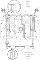
(実施例) 図1ないし図10は本発明に係る椅子式のマッサージ装置の実施例を示す。マッサージ装置は、図2に示すように、床面に載置される機台1と、機台1の上部に設けられる座部2およびひじ掛3と、座部2の後部に配置される倒伏自在な背もたれ4と、座部2の前側に配置される脚載部5と、脚載部5の下端に配置される足台6などで椅子状に構成してある。機台1、座部2、ひじ掛3、および背もたれ4で椅子本体を構成している。図3に示すように座部2およびひじ掛3の内部には、上腿および前腕をマッサージするエアセル10・11が設けてあり、背もたれ4の内部には、背中をマッサージする4個のエアセル12と、もみ玉13を備えたマッサージ装置14が設けてある。背もたれ4の左右両側に配置した肩受部7の内部にも、肩および上腕をマッサージするエアセル15が設けてある。 (Example) FIG. 1 thru | or FIG. 10 shows the Example of the chair type massage apparatus based on this invention. As shown in FIG. 2, the massage apparatus includes a machine base 1 placed on the floor surface, a seat 2 and an armrest 3 provided on the upper part of the machine base 1, and a lodging placed at the rear part of the seat 2. A free backrest 4, a leg rest 5 disposed on the front side of the seat 2, and a footrest 6 disposed at the lower end of the leg rest 5 are configured in a chair shape. The machine base 1, the seat 2, the armrest 3, and the backrest 4 constitute a chair body. As shown in FIG. 3, air cells 10 and 11 for massaging the upper thigh and the forearm are provided in the seat 2 and the armrest 3, and four air cells 12 for massaging the back are provided in the backrest 4. And the massage apparatus 14 provided with the fir ball 13 is provided. An air cell 15 for massaging the shoulder and upper arm is also provided inside the shoulder support 7 disposed on the left and right sides of the backrest 4.

脚載部5はフレーム18を基体にして構成してあり、その前部にふくらはぎを受け止める左右一対の下腿溝19が、前向きに開口する状態で凹み形成してある。下腿溝19の対向周面のそれぞれには、ふくらはぎをマッサージするエアセル(マッサージ体)20が設けてある。図3に示すように一対の下腿溝19は、横断面がコ字状の隔壁21を共有する状態で左右に区分してある。足台6は台枠22を基体にして構成してあり、その上面に足を受け止める左右一対の足受溝23が、上向きに開口する状態で凹み形成してある。足受溝23の対向周面と溝底のそれぞれには、くるぶし、および土踏まずをマッサージするエアセル(マッサージ体)24が設けてある。台枠22の後端下部には、床面で受け止められる車輪25が組み付けてある(図4参照)。   The leg rest part 5 is configured by using a frame 18 as a base body, and a pair of left and right crus grooves 19 for receiving a calf are recessed in a front part thereof so as to open forward. An air cell (massage body) 20 for massaging the calf is provided on each of the opposed peripheral surfaces of the lower leg groove 19. As shown in FIG. 3, the pair of lower leg grooves 19 are divided into left and right in a state in which a partition wall 21 having a U-shaped cross section is shared. The footrest 6 has a frame 22 as a base body, and a pair of left and right foot-receiving grooves 23 for receiving the foot are formed in a concave shape in a state of opening upward. An air cell (massage body) 24 for massaging the ankle and the arch is provided on each of the opposed peripheral surface of the foot receiving groove 23 and the groove bottom. A wheel 25 that is received on the floor surface is assembled to the lower end of the underframe 22 (see FIG. 4).

脚載部5は、機台1の前部に密着する旋回待機位置(図2に実線で示す状態)と、座部2の前端下部に設けた旋回軸26の回りに上方旋回操作される旋回位置(図2に想像線で示す状態)とに姿勢変更できる。そのために、先の旋回軸26の回りに上下旋回可能に支持されるべース枠27と椅子本体との間に、べース枠27を介して脚載部5を上下旋回操作する旋回機構を設けている。旋回軸26は機台1の前面上部に固定したブラケット28で支持してある。   The leg rest 5 is a swivel standby position (closed by a solid line in FIG. 2) that is in close contact with the front of the machine base 1 and a swivel that is swung upward around a swivel shaft 26 provided at the lower front end of the seat 2. The posture can be changed to a position (a state indicated by an imaginary line in FIG. 2). For this purpose, a turning mechanism for turning the leg rest 5 up and down via the base frame 27 between the chair frame and the base frame 27 supported so as to turn up and down around the previous turning shaft 26. Is provided. The pivot shaft 26 is supported by a bracket 28 fixed to the upper front portion of the machine base 1.

図5に示すように、べース枠27は左右一対のチルトアーム30と、両チルトアーム30を橋絡する状態で固定される4個の桟体31とで構成してあり、両チルトアーム30の上端が、先に説明した旋回軸26で旋回可能に軸支してある。上側2個の桟体31の前面の左右中央にはブラケット32が固定され、ブラケット32の背面一側にはローラー受板33が固定してある。また、下側2個の桟体31の前面の左右には、後述するガイドローラー47が組み付けてあり、一方のガイドローラー47の一側近傍に光センサー34が固定してある。チルトアーム30は金属管材で、桟体31は四角筒状のチャンネル材で形成してある。   As shown in FIG. 5, the base frame 27 is composed of a pair of left and right tilt arms 30 and four crosspieces 31 fixed so as to bridge both the tilt arms 30. The upper end of 30 is pivotally supported by the swivel shaft 26 described above. A bracket 32 is fixed to the left and right centers of the front surfaces of the upper two bars 31, and a roller receiving plate 33 is fixed to one side of the rear surface of the bracket 32. Further, guide rollers 47 to be described later are assembled on the left and right sides of the front surfaces of the two lower bars 31, and an optical sensor 34 is fixed near one side of the one guide roller 47. The tilt arm 30 is formed of a metal tube material, and the crosspiece 31 is formed of a square cylindrical channel material.

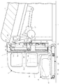
図4に示すように旋回機構は、機台1の内部に配置されるモーターシリンダー37と、モーターシリンダー37で旋回操作される操作アーム38とで構成してある。モーターシリンダー37は、モーター動力で雌ねじ体を回転駆動し、雌ねじ体で操作ねじ軸39を出退操作する。操作アーム38は、先の旋回軸26の下方に設けた揺動軸40で前後揺動可能に支持してあり、その先端にローラー41が回転自在に軸支してある。ローラー41は、ローラー受板33を介してべース枠27を押し上げ操作する。操作ねじ軸39の突端は、操作アーム38の下部に連結してある。   As shown in FIG. 4, the turning mechanism is constituted by a motor cylinder 37 disposed inside the machine base 1 and an operation arm 38 that is turned by the motor cylinder 37. The motor cylinder 37 rotationally drives the internal thread body with motor power, and moves the operation screw shaft 39 out and out with the internal thread body. The operation arm 38 is supported by a swing shaft 40 provided below the pivot shaft 26 so as to be swingable back and forth, and a roller 41 is rotatably supported at the tip thereof. The roller 41 pushes up the base frame 27 via the roller receiving plate 33. The protruding end of the operation screw shaft 39 is connected to the lower part of the operation arm 38.

使用者の好みや下腿の長さに応じて脚載部5や足台6を伸縮変位させるために、脚載部5のフレーム18とべース枠27との間に第1伸縮機構を設け、足台6の台枠22とべース枠27との間に第2伸縮機構を設けている。第1伸縮機構は、脚載部5の背面側に位置するフレーム18とベース枠27との間に設けられる第1ガイド構造と、後述するモーター53を駆動源にしてフレーム18を往復駆動操作するフレーム駆動構造とで構成する。   A first telescopic mechanism is provided between the frame 18 of the leg rest 5 and the base frame 27 in order to expand and contract the leg rest 5 and the footrest 6 according to the user's preference and the length of the lower leg. A second telescopic mechanism is provided between the base frame 22 and the base frame 27 of the footrest 6. The first telescopic mechanism reciprocally drives the frame 18 using a first guide structure provided between the frame 18 positioned on the back side of the leg rest 5 and the base frame 27 and a motor 53 described later as a drive source. And frame drive structure.

図5に示すようにフレーム18は、上下一対の横枠44と、両横枠44の側端寄りに固定される左右一対のスライド軸45と、両スライド軸45の間に固定されるモーターベース46などで構成してある。スライド軸45は金属管材で形成してあり、このスライド軸45と、ベース枠27に配置したガイドローラー47とで第1ガイド構造を構成している。図6および図7に示すようにガイドローラー47は、ベース枠27に固定されるコ字状のローラーブラケット48と、ローラーブラケット48の対向壁の前後および上下に軸支される4個のローラー軸49と、ローラー軸49で軸支される前後一対のローラー50とで構成する。ローラー50の周面には、スライド軸45の周面を受け止める凹溝が周回状に形成してある。   As shown in FIG. 5, the frame 18 includes a pair of upper and lower horizontal frames 44, a pair of left and right slide shafts 45 fixed to the side ends of both horizontal frames 44, and a motor base fixed between the slide shafts 45. 46 or the like. The slide shaft 45 is formed of a metal tube, and the slide shaft 45 and the guide roller 47 disposed on the base frame 27 constitute a first guide structure. As shown in FIGS. 6 and 7, the guide roller 47 includes a U-shaped roller bracket 48 fixed to the base frame 27, and four roller shafts pivotally supported on the front and rear and up and down of the opposing wall of the roller bracket 48. 49 and a pair of front and rear rollers 50 supported by a roller shaft 49. On the peripheral surface of the roller 50, a concave groove for receiving the peripheral surface of the slide shaft 45 is formed in a circular shape.

図8においてフレーム駆動構造は、モーターベース46に固定されるモーター(ギヤードモーター)53と、モーター53で回転駆動される送りねじ軸54と、送りねじ軸54に噛み合う雌ねじ体55とで構成する。送りねじ軸54の一端はモーター53の出力部に連結され、他端はモーターベース46に固定した軸受56で軸支してある。雌ねじ体55の左右両側には連結軸57が突設してあり、これらの連結軸57を図6に示すようにベース枠27に固定したブラケット32の連結溝58に係合することにより、雌ねじ体55がブラケット32と一体化してある。   In FIG. 8, the frame drive structure includes a motor (geared motor) 53 fixed to the motor base 46, a feed screw shaft 54 that is rotationally driven by the motor 53, and a female screw body 55 that meshes with the feed screw shaft 54. One end of the feed screw shaft 54 is connected to the output portion of the motor 53, and the other end is pivotally supported by a bearing 56 fixed to the motor base 46. Connection shafts 57 project from the left and right sides of the female screw body 55. By engaging these connection shafts 57 with the connection grooves 58 of the bracket 32 fixed to the base frame 27 as shown in FIG. A body 55 is integrated with the bracket 32.

上記のように、雌ねじ体55をブラケット32と一体化すると、モーター53で送りねじ軸54を正逆いずれかへ回転駆動するとき、モーター53および送りねじ軸54が雌ねじ体55に対して上下移動する。これにより、脚載部5をベース枠27に対して伸長待機位置と最大伸長位置との間で伸縮操作することができる。図4に示すように、モーターベース46に固定したモーター53は、モーターベース46の前方に大きく突出するが、先に説明した隔壁21で囲まれる空間の内部にモーター53を配置すると、モーター53が邪魔になるのを防止でき、外観上の体裁も同時に向上できる。   As described above, when the female screw body 55 is integrated with the bracket 32, the motor 53 and the feed screw shaft 54 move up and down with respect to the female screw body 55 when the motor 53 rotates the feed screw shaft 54 forward or backward. To do. Thereby, the leg rest part 5 can be expanded and contracted with respect to the base frame 27 between the extension standby position and the maximum extension position. As shown in FIG. 4, the motor 53 fixed to the motor base 46 largely protrudes in front of the motor base 46, but if the motor 53 is disposed in the space surrounded by the partition wall 21 described above, the motor 53 is It can be prevented from getting in the way, and the appearance can be improved at the same time.

第2伸縮機構は、足台6の下面に配置される台枠22とベース枠27との間に設けられて、台枠22を往復スライド自在に案内支持する第2ガイド構造と、台枠22を復帰付勢するばね61とで構成する。   The second telescopic mechanism is provided between the base frame 27 and the base frame 27 disposed on the lower surface of the footrest 6, and has a second guide structure that guides and supports the base frame 22 so as to be slidable back and forth, and the base frame 22. And a spring 61 for returning and energizing.

図5に示すように台枠22は金属管材を素材にして形成してあり、垂直に延びる左右一対のスライド軸62と、スライド軸62の下端に連続して前向きに折り曲げられるコ字枠63とで、側面から見てL字枠状に形成する。図4に示すようにコ字枠63には、底板64と補強桟65、および車輪25を軸支する車輪枠が固定してある。スライド軸62と、ベース枠27に配置したガイドローラー67とで第2ガイド構造を構成している。   As shown in FIG. 5, the base frame 22 is made of a metal tube material, and includes a pair of left and right slide shafts 62 that extend vertically, and a U-shaped frame 63 that is bent forward continuously at the lower end of the slide shaft 62. Thus, it is formed in an L-shaped frame shape when viewed from the side. As shown in FIG. 4, the bottom frame 64, the reinforcing bar 65, and the wheel frame that pivotally supports the wheel 25 are fixed to the U-shaped frame 63. The slide shaft 62 and the guide roller 67 arranged on the base frame 27 constitute a second guide structure.

図6および図7に示すようにガイドローラー67は、先に説明したガイドローラー47とローラーブラケット48、および4個のローラー軸49を共用する状態で構成してあり、前後一対のローラー68を4個のローラー軸49で遊転自在に支持して構成する。このように、ローラーブラケット48およびローラー軸49を共用することによりガイドローラー47・67を一体化してガイド構造を簡素化し、コンパクト化できる。また、ローラー50・68を共通するローラー軸49で軸支することにより、第1ガイド構造のスライド軸45と、第2ガイド構造のスライド軸62とを近接配置して、平行な姿勢で案内支持できる。各ローラー68の周面には、スライド軸62の周面を受け止める凹溝が周回状に形成してある。   As shown in FIGS. 6 and 7, the guide roller 67 is configured to share the guide roller 47, the roller bracket 48, and the four roller shafts 49 described above, and includes a pair of front and rear rollers 68. Each roller shaft 49 is supported so as to be freely rotatable. Thus, by sharing the roller bracket 48 and the roller shaft 49, the guide rollers 47 and 67 can be integrated to simplify the guide structure and make it compact. Further, by supporting the rollers 50 and 68 with a common roller shaft 49, the slide shaft 45 of the first guide structure and the slide shaft 62 of the second guide structure are arranged close to each other and guided and supported in a parallel posture. it can. A concave groove for receiving the peripheral surface of the slide shaft 62 is formed in a circular shape on the peripheral surface of each roller 68.

ばね61は引っ張りばねで形成してあり、全体がスライド軸62の内部に収容されて、その下端がスライド軸62に固定したピン69に掛止され、上端がフレーム18の上側の横枠44に掛止してある(図1参照)。このように台枠22をばね61で移動付勢することにより、足台6が脚載部5の下面に密着する伸長待機位置へ向かって台枠22の全体を復帰操作できる。また、ばね61の上端を上側の横枠44に掛止するので、脚載部5の伸縮位置とは無関係にばね61を伸縮変位でき、したがって足台6をより軽い力で伸長変位できる。   The spring 61 is formed of a tension spring and is entirely accommodated in the slide shaft 62, and its lower end is hooked on a pin 69 fixed to the slide shaft 62, and its upper end is attached to the horizontal frame 44 on the upper side of the frame 18. It is hooked (see FIG. 1). Thus, by moving and biasing the frame 22 with the spring 61, the entire frame 22 can be returned to the extension standby position where the foot 6 is in close contact with the lower surface of the leg rest 5. In addition, since the upper end of the spring 61 is hooked on the upper horizontal frame 44, the spring 61 can be expanded and contracted regardless of the expansion / contraction position of the leg rest 5, so that the footrest 6 can be extended and displaced with a lighter force.

因みに、ばね61の上端がベース枠27に固定してある場合には、脚載部5が伸長変位するときにばね61が撓み変形するのを避けられず、その分だけ足台6を伸長変位させるときに大きな力を要することになる。横枠44には、スライド軸62に内嵌する短寸のガイド筒70が固定してあり、このガイド筒70によって伸長待機状態のスライド軸62の振れを規制できる。足台6が伸長限界を越えて伸長操作されるのを防ぐために、図9に示すようにフレーム18の下側の横枠44と補強桟65との間に牽制ベルト71を設けている。   Incidentally, when the upper end of the spring 61 is fixed to the base frame 27, it is inevitable that the spring 61 bends and deforms when the leg rest 5 is extended and displaced, and the footrest 6 is extended and displaced by that amount. It takes a lot of power to make it happen. A short guide tube 70 that fits inside the slide shaft 62 is fixed to the horizontal frame 44, and the swing of the slide shaft 62 in the extension standby state can be restricted by the guide tube 70. In order to prevent the footrest 6 from being extended beyond the extension limit, a check belt 71 is provided between the lower horizontal frame 44 and the reinforcing bar 65 as shown in FIG.

先に説明したように、脚載部5はモーター53を駆動源とするフレーム駆動構造で駆動するが、脚載部5の現在の変位量を検出するために、ベース枠27とフレーム18との間にセンシング構造を設けている。図5および図6においてセンシング構造は、ベース枠27に固定される光センサー34と、フレーム18のモーターベース46に固定される帯板状のセンシング枠73とで構成する。光センサー34は、投光部74と受光部75とを対向配置して構成してある。センシング枠73の板面には、投光部74から照射される検知光の通過を許す検知穴76の一群が一定間隔おきに直線列状に形成してある。   As described above, the leg rest 5 is driven by the frame drive structure using the motor 53 as a drive source. In order to detect the current displacement amount of the leg rest 5, the base frame 27 and the frame 18 A sensing structure is provided between them. 5 and 6, the sensing structure includes an optical sensor 34 fixed to the base frame 27 and a strip-shaped sensing frame 73 fixed to the motor base 46 of the frame 18. The optical sensor 34 is configured by arranging a light projecting unit 74 and a light receiving unit 75 to face each other. On the plate surface of the sensing frame 73, a group of detection holes 76 that allow the detection light emitted from the light projecting unit 74 to pass is formed in a straight line at regular intervals.

脚載部5がベース枠27に対して上下動するとき、センシング枠73はフレーム18と共に上下動して、投光部74から照射される検知光を検知穴76を介して受光部75に受光させ、あるいは隣接する検知穴76の間の壁面によって検知光を遮断する。したがって、フレーム18の伸縮待機位置を基準にして、受光部75が出力した受光信号をカウントすることにより、脚載部5の現在位置を特定することができ、さらに脚載部5が伸縮ストロークの始端および終端の限界位置まで移行していることを特定できる。   When the leg rest 5 moves up and down with respect to the base frame 27, the sensing frame 73 moves up and down together with the frame 18, and the detection light emitted from the light projecting unit 74 is received by the light receiving unit 75 through the detection hole 76. Alternatively, the detection light is blocked by the wall surface between the adjacent detection holes 76. Therefore, the current position of the leg rest 5 can be specified by counting the light reception signal output from the light receiver 75 with reference to the expansion / contraction standby position of the frame 18. It is possible to specify that the position has shifted to the start and end limit positions.

次に、主として脚載部5および足台6の動作を説明する。マッサージ装置を使用するときは、使用者は座部2に着座し、適当な角度で後傾させた背もたれ4に背中をあずけ、両腕をひじ掛3に載せる。さらに下腿を脚載部5の左右の下腿溝19にあてがい、足を足台6の足受溝23に踏み込んだ状態でマッサージを行なう。このとき、図示していないコントローラーを操作してモーターシリンダー37を駆動することにより、脚載部5を背もたれ4の後傾姿勢に適合するように旋回変位できる。また、足台6をばね61の付勢力に抗して踏み出し操作することにより、使用者の下腿の長さに適合した位置まで足台6を伸長変位できる。さらに、コントローラーを操作してモーター53を駆動することにより、図10に示すように脚載部5を使用者のふくらはぎの位置に適合して昇降変位できる。   Next, operations of the leg rest 5 and the footrest 6 will be mainly described. When using the massage device, the user sits on the seat 2, places his back on the backrest 4 tilted backward at an appropriate angle, and puts both arms on the armrest 3. Further, the lower leg is applied to the left and right lower leg grooves 19 of the leg rest part 5, and massage is performed in a state where the foot is stepped on the foot receiving groove 23 of the footrest 6. At this time, by operating a controller (not shown) to drive the motor cylinder 37, the leg rest portion 5 can be turned and displaced so as to conform to the backward tilting posture of the backrest 4. Further, by stepping the footrest 6 against the urging force of the spring 61, the footrest 6 can be extended and displaced to a position suitable for the length of the user's lower leg. Furthermore, by operating the controller to drive the motor 53, the leg rest 5 can be displaced up and down in conformity with the position of the user's calf as shown in FIG.

図11に足載部5および足台6のエアセル20・24の制御構造を示す。そこでは、エアセル20・24に膨張用空気を供給する空気供給源80と、膨張用空気のエアセル20・24への給排気状態を切り換える分配装置81と、分配装置81の作動状態を制御する制御手段82とが設けてある。制御手段31は、座部2、ひじ掛3背もたれ4および肩受部7の設けたエアセル10・11・12・17などの動作状態も一括して制御しており、さらに、足載部5を昇降操作する第1伸縮機構や、足載部5旋回操作する旋回機構、あるいは背もたれ4のリクライニング機構も一括して制御している。図示していないが、分配装置81は各エアセルに対応して設けられる電磁弁の一群で構成してあり、各電磁弁を給気状態と排気状態とに切り換えることにより、各エアセルを膨張させ、あるいは収縮させることができる。   FIG. 11 shows a control structure of the air cells 20 and 24 of the footrest part 5 and the footrest 6. There, an air supply source 80 for supplying expansion air to the air cells 20, 24, a distribution device 81 for switching the supply / exhaust state of the expansion air to the air cells 20, 24, and a control for controlling the operating state of the distribution device 81. Means 82 are provided. The control means 31 collectively controls the operation states of the air cells 10, 11, 12, and 17 provided on the seat 2, the armrest 3 backrest 4, and the shoulder support 7, and further controls the footrest 5. The first elongating mechanism that moves up and down, the turning mechanism that turns the footrest portion 5 and the reclining mechanism of the backrest 4 are also controlled collectively. Although not shown, the distribution device 81 is configured by a group of electromagnetic valves provided corresponding to each air cell. By switching each electromagnetic valve between an air supply state and an exhaust state, each air cell is expanded, Alternatively, it can be shrunk.

上記のように、本発明のマッサージ装置では、脚載部5を椅子本体でベース枠27を介して支持し、脚載部5のフレーム18および足台6の台枠22を、それぞれベース枠27に対して第1伸縮機構と第2伸縮機構で個別に伸縮変位できるようにした。このように、脚載部5と台枠22をベース枠27に対して個別に伸縮変位できるマッサージ装置によれば、座部2に着座した状態で足台6を踏み出し操作することにより、足台6を使用者の下腿の長さに応じて伸長変位でき、その状態のままで脚載部5を使用者がマッサージしたい位置まで変位操作できる。したがって、下腿における「ふくらはぎ」や「くるぶし」の位置の個人差とは無関係に、誰でもがふくらはぎ、くるぶし、足裏などのマッサージを好適に行なえる。必要があれば、脚載部5のエアセル20によって強く押圧される位置を、ふくらはぎの上下方向にずらして、好みの位置でマッサージを行なうことができる。脚載部5の旋回角度の違いによって、座部2から前方へ突出する下腿の突出量に違いが生じるが、その場合にも脚載部5を好みの位置まで伸縮変位させて、ふくらはぎやくるぶしを好適にマッサージできる。   As described above, in the massage device of the present invention, the leg rest 5 is supported by the chair body via the base frame 27, and the frame 18 of the leg rest 5 and the base frame 22 of the footrest 6 are respectively supported by the base frame 27. On the other hand, the first extension mechanism and the second extension mechanism can be individually extended and displaced. As described above, according to the massage device capable of individually extending and retracting the leg rest portion 5 and the base frame 22 with respect to the base frame 27, the footrest 6 can be stepped on while being seated on the seat portion 2. 6 can be extended and displaced according to the length of the user's lower leg, and the displacement can be performed to the position where the user wants to massage the leg rest portion 5 in this state. Accordingly, regardless of individual differences in the positions of the “calves” and “ankles” on the lower leg, anyone can suitably perform massages such as calves, ankles and soles. If necessary, massage can be performed at a desired position by shifting the position of the leg rest portion 5 pressed strongly by the air cell 20 in the vertical direction of the calf. A difference in the amount of protrusion of the lower leg projecting forward from the seat part 2 occurs due to the difference in the turning angle of the leg rest part 5, but in that case, the leg rest part 5 is expanded and contracted to a desired position, so that the calf and the ankle Can be suitably massaged.

また、本発明のマッサージ装置によれば、以下のマッサージ態様で足裏やふくらはぎのマッサージを行なえる。そのひとつは、足台6で足を受け止めた状態において、脚載部5を上下に往復駆動するマッサージ態様である。足台6を復帰付勢するばね61の上端はフレーム18の横枠44に掛止してある。そのため、足を足台6で受け止めた状態において脚載部5を上下に往復駆動すると、足台6と脚載部5の上下間隔が変化し、その分だけばね61が伸縮変形しばね圧が変化する。したがって、足台6で足を受け止めた状態において脚載部5を上下に往復駆動するマッサージ態様を実行することにより、足裏に作用する押圧力を変化させて、足裏のマッサージを行なうことができる。   Moreover, according to the massage apparatus of this invention, the foot sole and the calf can be massaged in the following massage modes. One of them is a massage mode in which the leg rest part 5 is reciprocated up and down in a state where the foot is received by the footrest 6. The upper end of the spring 61 for returning and biasing the footrest 6 is hooked to the horizontal frame 44 of the frame 18. Therefore, when the leg rest 5 is reciprocated up and down while the foot is received by the footrest 6, the vertical distance between the footrest 6 and the leg rest 5 changes, and the spring 61 is expanded and contracted by that amount, and the spring pressure is increased. Change. Therefore, by performing a massage mode in which the footrest 5 is reciprocated up and down in a state where the foot is received by the footrest 6, the pressing force acting on the sole can be changed to perform the massage of the sole. it can.

他のマッサージ態様では、脚載部5を上下に往復駆動しながら、エアセル20を膨縮させる。このマッサージ態様では、足を足台6で受け止めた状態において、脚載部5が足側からひざ側へ向かって間欠的に移動するように、モーター53の動作状態を制御手段82でする。さらに、先のモーター53を停止させた状態において、下側一対のエアセル20と上側一対のエアセル20を記載順に膨縮させて、ふくらはぎをマッサージする。脚載部5が上昇限界位置まで移動したら、脚載部5を再び下降限界位置まで移動して、ふくらはぎを足側からひざ側へ向かって繰り返しマッサージする。このマッサージ態様においても、上記のマッサージ態様と同様に、足裏に作用するばね61のばね圧を変化させて、足裏のマッサージを行なうことができる。   In another massage mode, the air cell 20 is expanded and contracted while the leg rest 5 is reciprocated up and down. In this massage mode, the operation state of the motor 53 is controlled by the control means 82 so that the leg rest 5 moves intermittently from the foot side to the knee side in a state where the foot is received by the footrest 6. Further, in a state where the previous motor 53 is stopped, the lower pair of air cells 20 and the upper pair of air cells 20 are expanded and contracted in the order of description to massage the calf. When the leg rest part 5 moves to the ascending limit position, the leg rest part 5 is moved again to the descending limit position, and the calf is repeatedly massaged from the foot side toward the knee side. Also in this massage mode, the foot pressure can be massaged by changing the spring pressure of the spring 61 acting on the sole, as in the above massage mode.

さらに、上記のように脚載部5を上下に往復駆動しながらエアセル20を膨縮させるマッサージ態様においては、上下のエアセル20を膨張ないし半膨張状態にした状態で、脚載部5を足側からひざ側へ向かって連続して上昇させ、ふくらはぎを上下のエアセル20で上向きに擦るようにしてマッサージを行なうことができる。   Furthermore, in the massage mode in which the air cell 20 is expanded and contracted while the leg rest 5 is reciprocated up and down as described above, the leg rest 5 is placed on the foot side with the upper and lower air cells 20 in an inflated or semi-expanded state. The massage can be performed by continuously raising from the knee toward the knee side and rubbing the calf upward with the upper and lower air cells 20.

上記の実施例では、モーター53の回転動力を送りねじ軸54と雌ねじ体55で往復動力に変換したが、その必要はない。例えば、ラックとピニオンを変換要素にして、あるいはタイミングベルトとタイミングプーリーを変換要素にして、モーター53の回転動力を往復動力に変換することができる。脚載部5および足台6に設けるマッサージ体20・24はエアセルである必要はなく、皮膚表面を擦るマッサージ要素や、ふくらはぎや足裏を機械的に揉みほぐすマッサージ要素であってもよい。足台6に設けられるマッサージ体24はエアセルである必要はなく、動力で駆動されるマッサージ体や、足裏に圧迫刺激を与えるための非駆動型の突起状のマッサージ体であってもよい。第2伸縮機構はばね61で復帰付勢する必要はなく、手動で足台6の位置を変位操作してもよい。また、第2伸縮機構を第1伸縮機構と同様にモーターを駆動源にして自動的に伸縮することができる。   In the above embodiment, the rotational power of the motor 53 is converted into reciprocating power by the feed screw shaft 54 and the female screw body 55, but this is not necessary. For example, the rotational power of the motor 53 can be converted into reciprocating power using a rack and pinion as conversion elements, or a timing belt and timing pulley as conversion elements. The massage bodies 20 and 24 provided on the leg rest 5 and the footrest 6 do not have to be air cells, and may be massage elements that rub the skin surface, or massage elements that mechanically massage the calves and soles. The massage body 24 provided on the footrest 6 does not need to be an air cell, and may be a massage body driven by power, or a non-drive-type protruding massage body for applying a compression stimulus to the sole. The second telescopic mechanism does not need to be biased back by the spring 61, and the position of the footrest 6 may be manually displaced. Further, the second expansion / contraction mechanism can be automatically expanded / contracted using the motor as a drive source in the same manner as the first expansion / contraction mechanism.

2 座部
4 背もたれ
5 脚載部
6 足台
18 フレーム
19 下腿溝
20 エアセル(マッサージ体)
22 台枠
23 足受溝
24 エアセル(マッサージ体)
26 旋回軸
27 ベース枠
45 スライド軸
47 ガイドローラー
53 モーター
54 送りねじ軸
55 雌ねじ体
61 ばね
62 スライド軸
67 ガイドローラー
2 Seat part 4 Backrest 5 Leg rest part 6 Footrest 18 Frame 19 Lower leg groove 20 Air cell (massage body)
22 Underframe 23 Foot receiving groove 24 Air cell (massage body)
26 Rotating shaft 27 Base frame 45 Slide shaft 47 Guide roller 53 Motor 54 Feed screw shaft 55 Female screw body 61 Spring 62 Slide shaft 67 Guide roller

Claims (4)

背もたれ(4)と座部(2)を有する椅子本体と、前記座部(2)の前側に配置される脚載部(5)と、前記脚載部(5)を支持するベース枠(27)と、前記脚載部(5)の下端に配置される足台(6)と、前記脚載部(5)と前記足台(6)のそれぞれに設けられるマッサージ体(20・24)とを備えており
前記椅子本体に支持される前記脚載部(5)のフレーム(18)と前記ベース枠(27)との間に設けられて、該脚載部(5)を伸長待機位置と伸長位置との間で伸縮操作する第1伸縮機構と、前記足台(6)の台枠(22)と前記ベース枠(27)との間に設けられて、該足台(6)を伸長待機位置と伸長位置との間で伸縮操作する第2伸縮機構とを備え、これら第1伸縮機構と第2伸縮機構により、該脚載部(5)と該足台(6)とが、独立して伸縮変位できるように構成されており、
前記台枠(22)を移動付勢することにより、前記足台(6)を伸長待機位置へ向って復帰操作可能にするばね(61)が、前記台枠(22)を構成して垂直に延びるスライド軸(62)の内部に収容されており、
前記ばね(61)は、引っ張りばねで形成されており、その下端が前記台枠(22)に掛止され、上端が前記脚載部(5)のフレーム(18)に掛止されていることを特徴とする椅子式のマッサージ装置。
A chair body having a backrest (4) and a seat (2), a leg rest (5) disposed on the front side of the seat (2), and a base frame (27) supporting the leg rest (5) ) and the footrest section (footrest disposed at the lower end of the 5) (6), before Kiashino portion (5) and the massage member provided in each of the footrest (6) (20 - 24) It equipped with a door,
Provided between the base frame (27) and the frame (18) of the leg rest (5) supported by the chair body, the leg rest (5) is provided between an extension standby position and an extension position. A first telescopic mechanism for telescopic operation between the base frame (22) and the base frame (27) of the footrest (6). A second telescopic mechanism that performs an expansion / contraction operation between the position and the first telescopic mechanism and the second telescopic mechanism, whereby the leg rest (5) and the footrest (6) are independently expanded and contracted. Configured to be able to
A spring (61) enabling the footrest (6) to return to the extension standby position by moving and biasing the frame (22) constitutes the frame (22) vertically. Housed inside the extending slide shaft (62),
The said spring (61) is formed with the tension spring, The lower end is latched by the said frame (22), and an upper end is latched by the flame | frame (18) of the said leg mounting part (5) . A chair-type massage device.
前記足台(6)は、足裏が当接可能に構成されており、
使用者が前記座部(2)に着座した状態で前記足台(6)を踏み出して操作することにより、使用者の下腿の長さに応じて前記足台(6)を伸長変位することができるように構成されている、請求項1記載の椅子式のマッサージ装置。
The footrest (6) is configured such that the sole can come into contact with it,
When the user steps and operates the footrest (6) while sitting on the seat (2), the footrest (6) can be extended and displaced according to the length of the user's lower leg. The chair-type massage apparatus according to claim 1, configured to be able to perform.
前記第1伸縮機構が電動式である、請求項1または2記載の椅子式のマッサージ装置。 The first telescopic mechanism Ru motorized der, chair-type massaging apparatus as claimed in claim 1 or 2 wherein. 前記スライド軸(62)は、左右一対設けられており、
前記ばね(61)が、前記左右一対のスライド軸(62)の各々の内部に収容されている、請求項1乃至3のいずれかに記載の椅子式のマッサージ装置。
The slide shaft (62) is provided in a pair of left and right,
The chair type massage device according to any one of claims 1 to 3, wherein the spring (61) is housed inside each of the pair of left and right slide shafts (62).
JP2012195058A 2012-09-05 2012-09-05 Chair-type massage device Active JP5580858B2 (en)

Priority Applications (1)

Application Number Priority Date Filing Date Title
JP2012195058A JP5580858B2 (en) 2012-09-05 2012-09-05 Chair-type massage device

Applications Claiming Priority (1)

Application Number Priority Date Filing Date Title
JP2012195058A JP5580858B2 (en) 2012-09-05 2012-09-05 Chair-type massage device

Related Parent Applications (1)

Application Number Title Priority Date Filing Date
JP2008097157A Division JP5081041B2 (en) 2008-04-03 2008-04-03 Chair-type massage device

Publications (3)

Publication Number Publication Date
JP2012232202A JP2012232202A (en) 2012-11-29
JP2012232202A5 JP2012232202A5 (en) 2013-01-17
JP5580858B2 true JP5580858B2 (en) 2014-08-27

Family

ID=47433112

Family Applications (1)

Application Number Title Priority Date Filing Date
JP2012195058A Active JP5580858B2 (en) 2012-09-05 2012-09-05 Chair-type massage device

Country Status (1)

Country Link
JP (1) JP5580858B2 (en)

Cited By (1)

* Cited by examiner, † Cited by third party
Publication number Priority date Publication date Assignee Title
CN109125020A (en) * 2018-09-26 2019-01-04 尹明凤 A kind of leg massage instrument

Families Citing this family (1)

* Cited by examiner, † Cited by third party
Publication number Priority date Publication date Assignee Title
CN111772386A (en) * 2020-06-28 2020-10-16 嘉兴维特拉电气科技有限公司 Novel health care office massage chair

Family Cites Families (2)

* Cited by examiner, † Cited by third party
Publication number Priority date Publication date Assignee Title
AU2000238386A1 (en) * 2000-04-18 2001-10-30 Noriyasu Sakamoto Massaging machine
JP4009648B2 (en) * 2005-06-17 2007-11-21 ファミリー株式会社 Chair type massage machine

Cited By (1)

* Cited by examiner, † Cited by third party
Publication number Priority date Publication date Assignee Title
CN109125020A (en) * 2018-09-26 2019-01-04 尹明凤 A kind of leg massage instrument

Also Published As

Publication number Publication date
JP2012232202A (en) 2012-11-29

Similar Documents

Publication Publication Date Title
KR102111189B1 (en) Massage chair
JP5279190B2 (en) Massage chair
US20120245496A1 (en) Chair-type massaging machine provided with leg massaging device
JP2008178491A (en) Massage chair
JP2017113251A (en) Massage machine
US20190208911A1 (en) Rocking chair massager
JP4320196B2 (en) Resting chair type treatment machine
JP5081041B2 (en) Chair-type massage device
JP5408744B2 (en) Massage machine
JP5580858B2 (en) Chair-type massage device
JP6208938B2 (en) Massage machine
KR20210080338A (en) Massage device including leg massager with adjustable ankle angle
JP2007313105A (en) Chair type massage machine
US20210361523A1 (en) Massage chair having improved stretching functionality
JP5847613B2 (en) Chair type massage machine
JP4078676B2 (en) Chair type massage device
JP2020054629A (en) Massage machine
JP2009000157A (en) Massage machine
JP2003205007A (en) Chair with foot massage roller
JPH11244348A (en) Massage machine
KR102646795B1 (en) Massage apparatus having rotatable arm massage unit
JP5116318B2 (en) Chair massage machine
KR102653861B1 (en) Braces for upper body massage
KR102474164B1 (en) Massage apparatus
US20220401292A1 (en) Leg massager

Legal Events

Date Code Title Description
A521 Request for written amendment filed

Free format text: JAPANESE INTERMEDIATE CODE: A523

Effective date: 20121002

A621 Written request for application examination

Free format text: JAPANESE INTERMEDIATE CODE: A621

Effective date: 20121002

A521 Request for written amendment filed

Free format text: JAPANESE INTERMEDIATE CODE: A523

Effective date: 20121106

A977 Report on retrieval

Free format text: JAPANESE INTERMEDIATE CODE: A971007

Effective date: 20131025

A131 Notification of reasons for refusal

Free format text: JAPANESE INTERMEDIATE CODE: A131

Effective date: 20131030

A521 Request for written amendment filed

Free format text: JAPANESE INTERMEDIATE CODE: A523

Effective date: 20131225

TRDD Decision of grant or rejection written
A01 Written decision to grant a patent or to grant a registration (utility model)

Free format text: JAPANESE INTERMEDIATE CODE: A01

Effective date: 20140702

A61 First payment of annual fees (during grant procedure)

Free format text: JAPANESE INTERMEDIATE CODE: A61

Effective date: 20140711

R150 Certificate of patent or registration of utility model

Ref document number: 5580858

Country of ref document: JP

Free format text: JAPANESE INTERMEDIATE CODE: R150

R250 Receipt of annual fees

Free format text: JAPANESE INTERMEDIATE CODE: R250

S531 Written request for registration of change of domicile

Free format text: JAPANESE INTERMEDIATE CODE: R313531

S533 Written request for registration of change of name

Free format text: JAPANESE INTERMEDIATE CODE: R313533

R350 Written notification of registration of transfer

Free format text: JAPANESE INTERMEDIATE CODE: R350

R250 Receipt of annual fees

Free format text: JAPANESE INTERMEDIATE CODE: R250

R250 Receipt of annual fees

Free format text: JAPANESE INTERMEDIATE CODE: R250

R250 Receipt of annual fees

Free format text: JAPANESE INTERMEDIATE CODE: R250

S111 Request for change of ownership or part of ownership

Free format text: JAPANESE INTERMEDIATE CODE: R313117

R350 Written notification of registration of transfer

Free format text: JAPANESE INTERMEDIATE CODE: R350

R250 Receipt of annual fees

Free format text: JAPANESE INTERMEDIATE CODE: R250

R250 Receipt of annual fees

Free format text: JAPANESE INTERMEDIATE CODE: R250

R250 Receipt of annual fees

Free format text: JAPANESE INTERMEDIATE CODE: R250