JP5578377B2 - Substrate processing apparatus and method - Google Patents
Substrate processing apparatus and method Download PDFInfo
- Publication number
- JP5578377B2 JP5578377B2 JP2012166684A JP2012166684A JP5578377B2 JP 5578377 B2 JP5578377 B2 JP 5578377B2 JP 2012166684 A JP2012166684 A JP 2012166684A JP 2012166684 A JP2012166684 A JP 2012166684A JP 5578377 B2 JP5578377 B2 JP 5578377B2
- Authority
- JP
- Japan
- Prior art keywords
- gantry
- substrate
- nozzle
- processing liquid
- inkjet
- Prior art date
- Legal status (The legal status is an assumption and is not a legal conclusion. Google has not performed a legal analysis and makes no representation as to the accuracy of the status listed.)
- Active
Links
Images


Description
本発明は基板処理装置及び方法に関し、より詳細には液晶表示パネル等の工程処理を遂行する装置及び方法に関する。 The present invention relates to a substrate processing apparatus and method, and more particularly to an apparatus and method for performing process processing of a liquid crystal display panel or the like.
液晶表示パネルの製造工程は、ガラス基板表面に処理液を供給及び塗布する塗布工程と、処理液が塗布された基板にコーティング層を形成するコーティング工程と、を含む。塗布工程を遂行する装置として、インクジェット印刷方式で基板表面に直接処理液を印刷する装置が使用される。 The manufacturing process of the liquid crystal display panel includes an application process for supplying and applying a treatment liquid to the surface of the glass substrate, and a coating process for forming a coating layer on the substrate coated with the treatment liquid. As an apparatus for performing the coating process, an apparatus that directly prints the treatment liquid on the substrate surface by an inkjet printing method is used.
塗布工程とコーティング工程とは、工程に使用される装置が互いに異なり、独立した別個のチャンバーで工程が遂行されていた。そのため、塗布装置とコーティング装置との間で基板を移送するための移送装置が必要であった。このような装置は、全体設備面積を増加させるだけでなく、基板移送による全体工程時間を増加させるという問題がある。 The application process and the coating process are different from each other in apparatuses used in the processes, and the processes are performed in separate and independent chambers. Therefore, a transfer device for transferring the substrate between the coating device and the coating device is required. Such an apparatus not only increases the total equipment area, but also increases the total process time for substrate transfer.
本発明は、全体工程時間を短縮させ得る装置及び方法を提供することを課題とする。 It is an object of the present invention to provide an apparatus and method that can shorten the overall process time.
また、本発明は、設備全体面積が減少され得る装置及び方法を提供することを課題とする。 Moreover, this invention makes it a subject to provide the apparatus and method which can reduce the whole installation area.
また、本発明は、1つの装置で複数個の処理液を塗布できる装置及び方法を提供することを課題とする。 Moreover, this invention makes it a subject to provide the apparatus and method which can apply | coat a several process liquid with one apparatus.
本発明の基板処理装置は、基板を支持する基板支持ユニットと、前記基板に第1処理液を吐出するインクジェットノズルと、前記基板に第1処理液と異なる第2処理液を吐出するコーティングノズルと、前記基板支持ユニットに対して前記インクジェットノズルと前記コーティングノズルの位置が変更されるように前記インクジェットノズルと前記コーティングノズルとを第1方向に直線移動させるガントリーユニットと、を含む。 The substrate processing apparatus of the present invention includes a substrate support unit that supports a substrate, an inkjet nozzle that discharges a first processing liquid to the substrate, and a coating nozzle that discharges a second processing liquid different from the first processing liquid to the substrate. A gantry unit that linearly moves the inkjet nozzle and the coating nozzle in a first direction so that positions of the inkjet nozzle and the coating nozzle are changed with respect to the substrate support unit.
また、前記ガントリーユニットは前記インクジェットノズルを支持し、前記基板支持ユニットの上部を横切って前記基板支持ユニットの一側から他側へと前記第1方向に直線移動する第1ガントリーと、前記コーティングノズルを支持し、前記基板支持ユニットの上部を横切って前記基板支持ユニットの一側から他側へと前記第1方向に直線移動する第2ガントリーと、を包含できる。 Also, the gantry unit supporting said ink jet nozzle, a first gantry which moves linearly in the first direction and from one side of the substrate supporting unit across the top of the substrate supporting unit to the other side, said coating nozzle And a second gantry that moves linearly in the first direction from one side of the substrate support unit to the other side across the top of the substrate support unit.
また、前記第1ガントリーと前記第2ガントリーとは、前記基板支持ユニットの両側に互いに対向して前記第1方向に長く配置された一対のガイドレールに沿って直線移動することができる。 In addition, the first gantry and the second gantry can be linearly moved along a pair of guide rails that are long in the first direction so as to face each other on both sides of the substrate support unit.
また、前記コーティングノズルは、上部からみたとき、前記第1方向と垂直になる第2方向にその長さ方向が配置され、底面には前記第2処理液を吐出するスリットホールが前記第2方向に長く形成され得る。 The coating nozzle has a length direction arranged in a second direction perpendicular to the first direction when viewed from above, and a slit hole for discharging the second processing liquid is formed on the bottom surface in the second direction. Can be formed long.
また、前記第1ガントリーには前記インクジェットノズルが複数個装着され、前記インクジェットノズルは上部からみたとき、前記第1方向と垂直になる第2方向に配列され、前記第1ガントリーに対する前記インクジェットノズルの相対位置が変更されるように前記インクジェットノズルを前記第2方向に直線移動させるインクジェットノズル移動部をさらに包含できる。 The first gantry includes a plurality of ink jet nozzles, and the ink jet nozzles are arranged in a second direction perpendicular to the first direction when viewed from above, and the ink jet nozzles with respect to the first gantry are arranged. An inkjet nozzle moving unit that linearly moves the inkjet nozzle in the second direction so that the relative position is changed can be further included.
また、前記インクジェットノズルは複数個が前記第2方向に配列されて1つの列を形成し、前記インクジェットノズルの列は少なくとも2つ以上設けられ得る。 A plurality of the inkjet nozzles may be arranged in the second direction to form one row, and at least two or more rows of the inkjet nozzles may be provided.
また、前記ガントリーユニットは上部からみたとき、前記第1方向と垂直になる第2方向に対して前記第1ガントリーの長さ方向が所定角度だけ傾いて配置されるように前記第1ガントリーを回転させるガントリー駆動部をさらに包含できる。 The gantry unit rotates the first gantry so that the length direction of the first gantry is inclined at a predetermined angle with respect to a second direction perpendicular to the first direction when viewed from above. A gantry driving unit can be further included.
また、前記ガントリー駆動部は前記第1ガントリーの一端を回転中心として前記第1ガントリーの他端を回転させ得る。 Also, the gantry driving unit may rotate the other end of said first gantry as the center of rotation of one end of the first gantry.
また、前記ガントリーユニットは前記インクジェットノズルと前記コーティングノズルとを支持し、前記基板支持ユニットの上部を横切って前記基板支持ユニットの一側から他側へと前記第1方向に直線移動するガントリーを包含できる。 Further, it encompasses gantry the gantry unit supports and the coating nozzle and the jet nozzle, which moves linearly in the first direction and from one side of the substrate supporting unit across the top of the substrate supporting unit to the other side it can.
また、前記コーティングノズルは、上部からみたとき、前記第1方向と垂直になる第2方向にその長さ方向が配置され、底面には前記第2処理液を吐出するスリットホールが前記第2方向に長く形成され、前記第1方向に沿って前記コーティングノズルの前方と後方の各々の位置に、複数個の前記インクジェットノズルが前記第2方向に配列され得る。 The coating nozzle has a length direction arranged in a second direction perpendicular to the first direction when viewed from above, and a slit hole for discharging the second processing liquid is formed on the bottom surface in the second direction. The plurality of inkjet nozzles may be arranged in the second direction at positions in front of and behind the coating nozzle along the first direction.
本発明の基板処理方法は、基板支持ユニットの上部をインクジェットノズルが第1方向に直線移動し、第1処理液を前記基板支持ユニットに支持された基板に吐出する第1処理液吐出段階と、前記基板支持ユニットの上部をコーティングノズルが第1方向に直線移動し、前記第1処理液と異なる第2処理液を前記基板に吐出する第2処理液吐出段階と、を含み、前記第1処理液吐出段階と前記第2処理液吐出段階とは順次的に、且つ連続的に行われる。 The substrate processing method of the present invention includes a first processing liquid discharge stage in which an inkjet nozzle linearly moves in an upper direction of a substrate support unit in a first direction, and discharges a first processing liquid onto a substrate supported by the substrate support unit; A second processing liquid discharge stage in which a coating nozzle moves linearly in a first direction above the substrate support unit and discharges a second processing liquid different from the first processing liquid onto the substrate; The liquid discharge stage and the second treatment liquid discharge stage are performed sequentially and continuously.
また、前記インクジェットノズルは前記第1方向に直線移動可能である第1ガントリーに支持されて移動し、前記コーティングノズルは前記第1ガントリーと並べに配置され、前記第1方向に直線移動可能である第2ガントリーに支持されて移動することができる。 The inkjet nozzle is supported and moved by a first gantry that is linearly movable in the first direction, and the coating nozzle is arranged side by side with the first gantry and is linearly movable in the first direction. It is supported by the second gantry and can move.
また、前記インクジェットノズルは、上部からみたとき、前記第1方向と垂直になる第2方向に沿って複数個が一列に配列され、隣接する前記インクジェットノズルの間隔が固定され、前記第1ガントリーを所定角度回転させることで、前記第2方向の前記インクジェットノズルの間隔を変更させ得る。 In addition, when viewed from above, the inkjet nozzles are arranged in a line along a second direction perpendicular to the first direction, the interval between the adjacent inkjet nozzles is fixed, and the first gantry is fixed. The interval between the inkjet nozzles in the second direction can be changed by rotating the image by a predetermined angle.
また、前記インクジェットノズルと前記コーティングノズルとは、前記第1方向に直線移動可能であるガントリーに支持されて移動し、前記インクジェットノズルは、前記第1方向に沿った前記コーティングノズルの前方と後方と両方又は一方に位置することができる。 The inkjet nozzle and the coating nozzle are supported and moved by a gantry that is linearly movable in the first direction, and the inkjet nozzle is arranged in front of and behind the coating nozzle along the first direction. It can be located in both or one.
本発明によれば、装置との間に基板移送が必要とされないので、全体工程時間が短縮される。 According to the present invention, no substrate transfer is required between the apparatus and the entire process time.
また、本発明によれば、1つの装置で複数工程が遂行できるので、設備面積が減少される。 In addition, according to the present invention, since a plurality of processes can be performed with one apparatus, the facility area is reduced.
以下、添付図面を参照して、本発明の望ましい実施形態による基板処理装置及び方法を詳細に説明する。本発明を説明するに際して、関連する公知構成や機能に対する具体的な説明が本発明の要旨の理解を阻害すると判断される場合には、その詳細な説明は省略する。 Hereinafter, a substrate processing apparatus and method according to exemplary embodiments of the present invention will be described in detail with reference to the accompanying drawings. In describing the present invention, if it is determined that a specific description of related known configurations and functions impedes understanding of the gist of the present invention, detailed description thereof will be omitted.
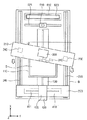
図1は本発明の一実施形態による基板処理装置を示す斜視図であり、図2は図1の基板処理装置を示す平面図である。 FIG. 1 is a perspective view showing a substrate processing apparatus according to an embodiment of the present invention, and FIG. 2 is a plan view showing the substrate processing apparatus of FIG.
図1及び図2に示すように、基板処理装置10は基板Sに処理液を塗布するものであり、基板支持ユニット100、ガントリーユニット200、第1処理液供給ユニット300、第2処理液供給ユニット400、ビジョン検査ユニット500、及びノズル洗浄ユニット600を含む。基板支持ユニット100は基板Sを支持し、ガントリーユニット200は第1処理液供給ユニット300のインクジェットノズル310と第2処理液供給ユニット400のコーティングノズル410とを直線移動させる。第1処理液供給ユニット300は基板Sに第1処理液を供給し、第2処理液供給ユニット400は第2処理液を供給する。ビジョン検査ユニット500はインクジェットノズル310とコーティングノズル410の異常の有無を検査し、ノズル洗浄ユニット600はインクジェットノズル310とコーティングノズル410とを洗浄する。以下、各構成に対して詳細に説明する。
As shown in FIGS. 1 and 2, the
基板支持ユニット100はベースBの上面に配置される。ベースBは一定の厚さを有する直六面体ブロックで設けられる。基板支持ユニット100は支持部材110、回転駆動部材(図示せず)、及び直線駆動部材120を含む。
The
支持部材110は基板Sを支持する。支持部材110は直四角形状の板で提供され、その上面に基板Sが置かれる。支持部材110は基板Sより大きい面積を有する。支持部材110の下部には回転駆動部材(図示せず)が配置される。回転駆動部材は支持部材110を回転させる。基板Sは支持部材110と共に回転される。
The
直線駆動部材120は、支持部材110と回転駆動部材とをレール130に沿って直線移動させる。以下、支持部材110が直線移動される方向を第1方向(X)とし、上部からみたとき、第1方向(X)と垂直になる方向を第2方向(Y)とする。そして、第1及び第2方向(X、Y)と垂直になる方向を第3方向(Z)とする。レール130はベースBの中心領域に第1方向(X)に沿って配置される。
The
ガントリーユニット200は、基板支持ユニット100に対してインクジェットノズル310とコーティングノズル410の位置が変更されるように、インクジェットノズル310とコーティングノズル410を第1方向(X)に直線移動させるものである。ガントリーユニット200は第1ガントリー210、第1ガントリー駆動部220、第2ガントリー250、及び第2ガントリー駆動部260を含む。
The
第1ガントリー210は、支持部材110の移動経路の上部に配置する。第1ガントリー210は、ベースBの上面から上方に所定距離だけ離隔して配置される。第1ガントリー210は、その長さ方向が第2方向(Y)に平行となるように配置される。
The
第1ガントリー駆動部220は第1ガントリー210を第1方向(X)に直線移動させる。第1ガントリー駆動部220は、支持部材110の上部を横切って支持部材110の一側から他側へと第1方向(X)に直線移動させる。そして、第1ガントリー駆動部220は、第1ガントリー210が第2方向(Y)に対して所定角度に傾いて配置されるように、第1ガントリー210を回転させる。第1ガントリー駆動部220は、第1ガントリー210の一端を回転中心として第1ガントリー210を回転させる。なお、第1ガントリー駆動部220は、第1ガントリー210の中心を軸として第1ガントリー210を回転させるものでもよい。第1ガントリー駆動部220は第1駆動部230と第2駆動部240とを含む。第1駆動部230は第1ガントリー210の一端の下部に設けられ、第2駆動部240は第1ガントリー210の他端の下部に設けられる。
The first
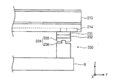
図3は図1の第1駆動部を示す図面である。図3に示すように、第1駆動部230は第1スライダー231、第1回転支持部材232、及び第1直線駆動部材234を含む。
FIG. 3 is a diagram illustrating the first driving unit of FIG. As shown in FIG. 3, the
第1スライダー231は、第1ガントリー210の底面にその横方向に沿って形成されたガイド溝214に案内されて直線移動する。第1スライダー231の下端部には第1回転支持部材232が結合する。第1回転支持部材232は第1直線駆動部材234に対して第1スライダー231が相対回転できるように設けられる。第1回転支持部材232はベアリングを含む。
The
第1回転支持部材232の下端には第1直線駆動部材234が結合される。第1直線駆動部材234は第1回転支持部材232を第1方向(X)に直線移動させる。第1直線駆動部材234はスライダー235とガイドレール236とを含む。ガイドレール236はベースBの一側にて第1方向(X)に沿って配置される。ガイドレール236にはスライダー235が移動自在に結合される。スライダー235の上端には第1回転支持部材232が結合する。スライダー235にはリニアモーターが内装され、スライダー235はリニアモーターの駆動力によって、ガイドレール236に沿って第1方向(X)に直線移動することができる。
A first
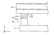
図4は第2駆動部を示す図面である。図4に示すように、第2駆動部240は第1ガントリー210が第1方向(X)に直線移動する場合、第1ガントリー210の他端を第1方向(X)に移動させる。そして、第2駆動部240は第1ガントリー210が回転する場合、第1ガントリー210の回転軸として動作する。第2駆動部240は連結部材241、第2回転支持部材242、及び第2直線駆動部材243を含む。連結部材241は第1ガントリー210の他端の底面に結合する。連結部材241の下端には第2回転支持部材242が結合する。第2回転支持部材242は第2直線駆動部材243に対して連結部材241が相対回転できるように設けられる。第2回転支持部材242はベアリングを含む。
FIG. 4 illustrates the second driving unit. As shown in FIG. 4, the
第2回転支持部材242の下端には第2直線駆動部材243が結合する。第2直線駆動部材243は第2回転支持部材242を第1方向(X)に直線移動させる。第2回転支持部材242の直線移動により、連結部材241と第1ガントリー210は共に直線移動する。
A second
第2直線駆動部材243はスライダー244とガイドレール245とを含む。ガイドレール245はベースBの他側にて第1方向(X)に沿って配置される。ガイドレール245は第1直線駆動部材234のガイドレール236と並んで配置される。ガイドレール245にはスライダー244が移動自在に結合する。スライダー244の上端には第2回転支持部材242が結合する。スライダー244にはリニアモーターが内装され、スライダー244はリニアモーターの駆動力によって、ガイドレール245に沿って第1方向(X)に直線移動することができる。
The second
図5は第1ガントリーが回転する形態を示す図面である。図3乃至図5に示すように、第1ガントリー210はその長さ方向が第2方向(Y)に対して傾くように回転可能であり、第1方向(X)に直線移動可能である。
FIG. 5 is a view showing a form in which the first gantry rotates. As shown in FIGS. 3 to 5, the
第1ガントリー210が回転する過程は、以下のとおりである。先ず、第2直線駆動部材243が固定された状態で第1直線駆動部材234が第1方向(X)に直線移動する。第1直線駆動部材234の移動にしたがって第1回転支持部材232が第1方向(X)に直線移動する。第1直線駆動部材234とスライダー231の相対移動によって第1回転支持部材232は回転する。スライダー231は第1ガントリー210のガイド溝214に沿って移動する。第1回転支持部材232は第1ガントリー210の動きによって回転する。このような動きによって、第1ガントリー210は回転されて第2方向(Y)に対して所定角度に傾くように配置され得る。
The process of rotating the
図1及び図2に示すように、第2ガントリー250は支持部材110の移動経路の上部に配置される。第2ガントリー250は第1ガントリー210と並んで配置される。
As shown in FIGS. 1 and 2, the
第2ガントリー駆動部260は第2ガントリー250を第1方向(X)に直線移動させる。第2ガントリー駆動部260は第2ガントリー250の両端の下端に各々設けられる。第2ガントリー駆動部260はガイドレール236、245に沿って第1方向(X)に直線移動する。
The second
第1処理液供給ユニット300は基板Sに第1処理液を吐出する。第1処理液供給ユニット300はインクジェットノズル310、インクジェットノズル移動部320、及び第1処理液供給部330を含む。
The first processing
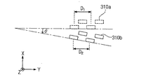
インクジェットノズル310は第1ガントリー210に設置される。インクジェットノズル310は複数個設けられる。インクジェットノズル310は第1方向(X)を前後方向としたときの第1ガントリー210の前面に、又は前面及び後面の各々に設置される。インクジェットノズル310は第1ガントリー210の横方向に離隔して複数配置される。インクジェットノズル310の間隔は固定されている。インクジェットノズル310は第2方向(Y)に沿って互いに異なる直線上に配置され、図示のようなジグザグ状に配置される。インクジェットノズル310の底面には、基板Sに第1処理液を吐出する吐出口が各々形成される。吐出口は基板Sに形成されたパターン間の空間に第1処理液を吐出する。インクジェットノズル310はインクジェット印刷方式で基板Sのパターン間の空間に第1処理液を直接印刷させることができる。第1ガントリー210の回転によって、インクジェットノズル310の第2方向(Y)の間隔が調節される。第1ガントリー210が回転されて第2方向(Y)に対して所定角度に傾いて配置される場合、図6のようにインクジェットノズル310も共に回転されて第2方向(Y)に対して傾くように配置される。このようなインクジェットノズル310の配置はインクジェットノズル310の第2方向(Y)の間の間隔を狭くする。例えば、第1ガントリー210が回転する前に、インクジェットノズル310aの間の間隔D1がlであるとする場合、第1ガントリー210が角度θ回転されると、インクジェットノズル310bの第2方向(Y)の間隔D2はl・cosθとなる。第1ガントリー210が回転される角度の大きさは、インクジェットノズル310の間隔と基板Sのパターン間隔とを考慮して決定される。このようなインクジェットノズル310の第2方向(Y)間隔調節によれば、基板Sのパターン間隔の変更にしたがってインクジェットノズル310の間の間隔を個別的に調節しなければならないという不便が解消される。
The
インクジェットノズル移動部320はインクジェットノズル310を第2方向(Y)に移動させる。インクジェットノズル移動部320はインクジェットノズル310と第1ガントリー210とを連結する連結ブロックを移動させ、これによりインクジェットノズル310は一体に移動される。インクジェットノズル310は第2方向(Y)に所定距離だけ移動することができる。インクジェットノズル310は第1方向(X)に第1処理液を吐出した後、第2方向(Y)に所定距離だけ移動する。そして、第1方向(X)に第1処理液を吐出する。このような第1処理液吐出によって基板Sの各領域に第1処理液が吐出される。
The inkjet
第1処理液供給部330はインクジェットノズル310の各々に第1処理液を供給する。第1処理液供給部330は、第1ガントリー210の上端に設置される。第1処理液供給部330は第1処理液格納部に供給される第1処理液を複数の股に分配してインクジェットノズル310の各々に供給する。これと異なり、第1処理液供給部330を、複数個の第1処理液格納部の各々から第1処理液をインクジェットノズル310の各々に供給するように設けてもよい。第1処理液は電気的特性を有するインキを含む。インキは印加された電流の大きさにしたがってその形状が変わる。インキは印加された電流の大きさにしたがって拡散程度が異なることもある。第1処理液は低い親水性を有することができ、例えば油性インキ(oil ink)を含む。
The first processing
第2処理液供給ユニット400は基板Sに第2処理液を吐出する。第2処理液供給ユニット400はコーティングノズル410、第2処理液供給部420、コーティングノズル制御部430を含む。
The second processing
コーティングノズル410は第2ガントリー250の下部に位置し、第2ガントリー250に装着される。コーティングノズル410はその長さ方向が第2方向(Y)と平行になるように配置される。コーティングノズル410の底面には吐出口411が形成される。吐出口411はスリットホールから成り、コーティングノズル410の横方向に沿って形成される。吐出口411は基板Sの第2方向(Y)の幅に相当する長さか、或いはそれより長く設けられる。吐出口411は第2処理液を吐出する。
The
第2処理液供給部420は第2ガントリー250の上端に設置される。第2処理液供給部420は第2処理液格納部に格納された第2処理液を、供給ラインを通じてコーティングノズル410に供給する。第2処理液は第1処理液と異なるものであり、第1処理液とは混合されない。第2処理液は親水性が高い薬液であることができ、例えば水(water)を含む。
The second processing
コーティングノズル制御部430は、第2ガントリー250の前面に設置される。コーティングノズル制御部430はコーティングノズル410の動作を制御し、詳しくは、コーティングノズル410が吐出する第2処理液の流量及び吐出の周期等を制御することができる。
The
ビジョン検査ユニット500は、インクジェットノズル310とコーティングノズル410とを検査する。ビジョン検査ユニット500は第1方向(X)を前後方向としたときのベースBの後部に設置される。ビジョン検査ユニット500はカメラ510とカメラ移動部520とを含む。カメラ510はノズル310、410の吐出口を撮影する。撮影された映像からノズル310、410の吐出口の異常の有無を確認できる。カメラ移動部520は第2方向(Y)にカメラ510を移動させる。カメラ移動部520はガイドレール521と駆動器(図示せず)とを含む。ガイドレール521はその長さ方向が第2方向(Y)と平行に配置される。駆動器はカメラ510がガイドレール521に沿って移動するように駆動力を提供する。カメラ510はガイドレール521に沿って移動し、ノズル310、410の吐出口を連続的に撮影することができる。例えば、ビジョン検査ユニット500の上部にコーティングノズル410が位置する場合、カメラ510はコーティングノズル410の一端から他端へと第2方向(Y)に移動し、吐出口411を連続撮影することができる。
The
第1方向(X)を前後方向としたときのビジョン検査ユニット500の後方には、ノズル洗浄ユニット600が位置する。ノズル洗浄ユニット600は、インクジェットノズル310とコーティングノズル410の吐出口を洗浄する。ノズル洗浄ユニット600はハウジング610とローラー620とを含む。ハウジング610には、上面が開放された空間が内部に形成され、この空間内には洗浄液が格納される。ローラー620はハウジング610の内部で回転自在に装着される。ローラー620の上端はハウジング610の上端より高く位置する。ローラー620はその長さがコーティングノズル410の第2方向(Y)幅に対応するか、或いはそれより長く設けられる。ローラー620の上端はインクジェットノズル310の吐出口とコーティングノズル410の吐出口に相応する高さに位置される。また、ローラー620は高低が調節できるように設けられる。ローラー620は、インクジェットノズル310とコーティングノズル410の吐出口に接触された状態で回転し、インクジェットノズル310とコーティングノズル410の吐出口に残留する処理液や異物質を除去する。ローラー620表面に付いた処理液等は、ハウジング610内の洗浄液によって洗浄される。
The
以下においては、上述の基板処理装置を利用して基板を処理する方法について説明する。 Hereinafter, a method of processing a substrate using the above-described substrate processing apparatus will be described.
本発明の一実施形態による基板処理方法は、第1処理液吐出段階と第2処理液吐出段階とを含む。第1処理液吐出段階では第1処理液を基板Sに吐出し、第2処理液吐出段階では、第1処理液が吐出された基板Sに対して第2処理液を吐出する。第1処理液吐出段階と第2処理液吐出段階とは順次的であり、且つ連続的に遂行される。 A substrate processing method according to an embodiment of the present invention includes a first processing liquid discharge stage and a second processing liquid discharge stage. In the first processing liquid discharge stage, the first processing liquid is discharged onto the substrate S, and in the second processing liquid discharge stage, the second processing liquid is discharged onto the substrate S on which the first processing liquid has been discharged. The first treatment liquid discharge stage and the second treatment liquid discharge stage are sequential and performed continuously.
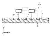
図7乃至図9は第1処理液吐出段階を示す図面である。 7 to 9 are views illustrating a first processing liquid discharge stage.
先ず、図7に示すように、インクジェットノズル310の第2方向(Y)の間隔が基板Sに形成されたパターンPの間隔と対応するように、第1ガントリー210が回転する。第1ガントリー210は、第1駆動部230と連結された一端が第1方向(X)に直線移動し、第2駆動部240と連結された他端が固定して位置し、これによって、第1ガントリー210は他端を中心として回転し、第2方向(Y)に対して所定角度(θ)傾くように配置される。また、第1駆動部230と第2駆動部240の駆動によって第1ガントリー210は第1方向(X)に直線移動する。第1ガントリー210は支持部材110の後部から前部へと直線移動する。インクジェットノズル310は基板S上部を通過する間に、第1処理液L1を基板Sに吐出する。図8のように、インクジェットノズル310の各々は基板SパターンP間の空間Aに第1処理液L1を吐出する。インクジェットノズル310はインクジェット印刷回路方式で第1処理液L1を基板Sに印刷させることができる。
First, as shown in FIG. 7, the
支持部材110の前部に移動した第1ガントリー210は図9のように、第1方向(X)に沿って支持部材110の後部に移動する。第1ガントリー210が移動する前に、インクジェットノズル310は第1ガントリー210の横方向に沿って所定距離を移動する。インクジェットノズル310は第1処理液L1が供給されない基板S領域の上部に移動する。インクジェットノズル310が移動した後、第1ガントリー210は支持部材110の後部に移動する。インクジェットノズル310は基板S上部を通過する間に、第1処理液L1を基板Sに吐出する。
The
第1ガントリー210が支持部材110の上部領域を横切って、支持部材110の前部と後部との間の区間を反復移動し、インクジェットノズル310が第1ガントリー210の横方向に沿って所定距離を移動することによって、基板Sの全体領域に第1処理液L1が吐出される。第1処理液吐出が完了した後、第1ガントリー210はベースBの後部に移動して控える。
The
第1処理液吐出段階が完了されれば、第2処理液吐出段階が順次的に、且つ連続的に進行される。 When the first treatment liquid discharge stage is completed, the second treatment liquid discharge stage proceeds sequentially and continuously.
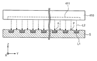
図10は第2処理液吐出段階を示す図面である。図10に示すように、第2ガントリー250が支持部材110の前部から後部に直線移動する。第2ガントリー250が基板Sの上部を通過する間に、コーティングノズル410は第1処理液が塗布された基板Sに対して第2処理液を吐出する。コーティングノズル410は基板Sの第2方向(Y)の幅に相応する吐出口411を有するので、図11のように1回の吐出で基板Sの全体領域に第2処理液L2を吐出することができる。第2ガントリー250は支持部材110の後部に移動した後、再び支持部材110の前部に復帰する。第2ガントリー250が復帰する過程で、コーティングノズル410は基板Sに再び第2処理液L2を吐出することができる。第2処理液L2は、第1処理液L1が塗布された空間Aに供給され、第1処理液L1上に塗布される。第2処理液L2は第1処理液L1が空気中に露出することを遮断する。
FIG. 10 is a diagram illustrating a second processing liquid discharge stage. As shown in FIG. 10, the
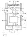
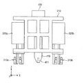
図12は本発明の他の実施形態による基板処理装置を示す斜視図であり、図13は図12の基板処理装置を示す平面図であり、図14は図12のガントリーと処理液供給部を示す正面図である。 12 is a perspective view showing a substrate processing apparatus according to another embodiment of the present invention, FIG. 13 is a plan view showing the substrate processing apparatus of FIG. 12, and FIG. 14 shows the gantry and the processing liquid supply unit of FIG. FIG.
図12乃至図14に示すように、基板処理装置は基板支持ユニット100、ガントリーユニット200、第1処理液供給ユニット300、第2処理液供給ユニット400、ビジョン検査ユニット500、及びノズル洗浄ユニット600を含む。基板支持ユニット100、ビジョン検査ユニット500、及びノズル洗浄ユニット600は図1の実施形態と同一の構造で設けられる。
12 to 14, the substrate processing apparatus includes a
ガントリーユニット200は、基板支持ユニット100に対してインクジェットノズル310とコーティングノズル410の位置が変更されるように、インクジェットノズル310とコーティングノズル410を第1方向(X)に直線移動させるものである。ガントリーユニット200はガントリー210、ガントリー駆動部230、240を含む。
The
図1の実施形態と異なり、ガントリーユニット200は単一のガントリー210を含む。ガントリー210は支持部材110の移動経路の上部に配置され、その長さ方向が第2方向(Y)と平行となるように配置される。
Unlike the embodiment of FIG. 1, the
ガントリー駆動部230、240はガントリー210を第1方向(X)に直線移動させる。ガントリー駆動部230、240は第1方向(X)に支持部材110の上部を横切って支持部材110の一側から他側へとガントリー210を移動させる。そして、ガントリー駆動部230、240はガントリー210が第2方向(Y)に対して所定角度だけ傾いて配置されるように、第1ガントリー210を回転させることができる。ガントリー駆動部230、240は図1の実施形態で説明した第1ガントリー駆動部(図1の230、240)と同一の構造で設けられる。
The
第1処理液供給ユニット300と第2処理液供給ユニット400はガントリー210に設置される。第1処理液供給ユニット300は基板Sに第1処理液を吐出する。第1処理液供給ユニット300はインクジェットノズル310、インクジェットノズル移動部320a、320b、及び第1処理液供給部330を含む。
The first processing
インクジェットノズル310はガントリー210に複数個設けられる。インクジェットノズル310は、第1方向(X)を前後方向としてガントリー210の前部と後部に各々設置される。インクジェットノズル310a、310bは第2方向(Y)に沿って一列又は複数列に配列される。同一の列に配置されたインクジェットノズル310a、310bは第2方向(Y)に沿って互いに離隔して配置される。インクジェットノズル310の底面には吐出口が各々形成される。吐出口は第1処理液を吐出する。
A plurality of
インクジェットノズル移動部320a、320bはインクジェットノズル310を第2方向(Y)へと一体に移動させる。
The inkjet
第1処理液供給部330はガントリー210に設置される。第1処理液供給部330はインクジェットノズル310の各々に第1処理液を供給する。
The first processing
第2処理液供給ユニット400は基板Sに第2処理液を吐出する。第2処理液供給ユニット400はコーティングノズル410、第2処理液供給部420、及びコーティングノズル制御部430を含む。
The second processing
コーティングノズル410はガントリー210の下部に位置し、ガントリー210に支持される。コーティングノズル410はその長さ方向がガントリー210の長さ方向と平行となるように配置される。コーティングノズル410はガントリー210の前部に位置したインクジェットノズル310aとガントリー210の後部に位置したインクジェットノズル310bとの間の領域に配置される。コーティングノズル410の底面には吐出口411が形成される。吐出口411は基板Sの第2方向(Y)の幅に相応する長さか、或いはそれより長く設けられる。吐出口411は第2処理液を吐出する。
The
第2処理液供給部420はガントリー210に設置される。第2処理液供給部420はコーティングノズル410に第2処理液を供給する。
The second processing
コーティングノズル制御部430はガントリー210に設置される。コーティングノズル制御部430はコーティングノズル410の動作を制御し、詳しくは、コーティングノズル410が吐出する第2処理液の流量及び吐出の周期等を制御することができる。
The coating
上述した基板処理装置による場合、インクジェットノズル310とコーティングノズル410とは1つのガントリー210によって移動する。ガントリー210が支持部材110の上部領域を横切って支持部材110の前部から後部に反復移動し、このとき、インクジェットノズル310とコーティングノズル410が基板Sに処理液を吐出する。インクジェットノズル310が基板Sの全体領域に第1処理液を吐出した後、順次的にコーティングノズル410が第2処理液を吐出することができる。
In the case of the substrate processing apparatus described above, the
図15は本発明のその他の実施形態による基板処理装置を示す図面である。図15に示すように、図13の実施形態と異なり、コーティングノズル410の第2方向(Y)の長さはインクジェットノズル310が第2方向(Y)に配列された幅W1と相応する長さに設けられる。コーティングノズル410には、吐出口411が第2方向(Y)に長く形成される。吐出口411はインクジェットノズル310が1回に処理液を吐出できる領域の第2方向(Y)の幅に相応する長さを有する。コーティングノズル410はコーティングノズル移動部によって、ガントリー210の長さ方向に移動することができる。コーティングノズル410はインクジェットノズル310と一体に移動するように設けてもよい。コーティングノズル移動部はガントリー210に設置される。
FIG. 15 is a view showing a substrate processing apparatus according to another embodiment of the present invention. As shown in FIG. 15, unlike the embodiment of FIG. 13, the length of the
ガントリー210が支持部材110の上部領域を移動する間に、コーティングノズル410とインクジェットノズル310とは図16のように、第1処理液L1と第2処理液L2を同時に基板Sに吐出することができる。ガントリー210が支持部材110の後部から前部に移動する間に、ガントリー210の前部に位置したインクジェットノズル310aが基板Sに第1処理液L1を吐出する。これと反対に、ガントリー210が支持部材110の前部から後部に移動する間に、ガントリー210の後部に位置したインクジェットノズル310bが基板Sに第1処理液を吐出する。基板Sに形成されたパターン間の空間には第1処理液L1が塗布された後、第2処理液L2が塗布される。コーティングノズル410とインクジェットノズル310a、310bは第1方向(X)への処理液吐出を完了した後、第2方向(Y)に所定距離だけ移動して、処理液が吐出されない基板S領域に第1及び第2処理液を順次的に吐出する。
While the
図16の実施形態による場合、ガントリー210の1回移動に第1及び第2処理液L1、L2が吐出できるので、図13の実施形態よりガントリー210の第1方向(X)への移動回数を減少させることができる。
If according to the embodiment of FIG. 16, the first and second treatment liquid L1, L2 in a single movement of the
以上の説明は、本発明の技術思想を例示的に説明するものに過ぎず、当業者であれば、本発明の本質的な特性を逸脱しない範囲で多様な修正及び変形が可能である。つまり、本発明の上述の実施形態は本発明の技術思想を限定するものではなく、単に説明するためのものであり、これらの実施形態によって本発明の技術思想の範囲は限定されない。本発明の保護範囲は特許請求の範囲によって解釈され、それと同等な範囲内にある全て技術思想は本発明の権利範囲に含まれる。 The above description is merely illustrative of the technical idea of the present invention, and various modifications and variations can be made by those skilled in the art without departing from the essential characteristics of the present invention. In other words, the above-described embodiments of the present invention are not intended to limit the technical idea of the present invention, but merely for explanation, and the scope of the technical idea of the present invention is not limited by these embodiments. The protection scope of the present invention is construed by the claims, and all technical ideas within the scope equivalent thereto are included in the scope of the right of the present invention.
10 基板処理装置
100 基板支持ユニット
200 ガントリーユニット
300 第1処理液供給ユニット
400 第2処理液供給ユニット
500 ビジョン検査ユニット
600 ノズル洗浄ユニット
DESCRIPTION OF
Claims (8)
前記基板に第1処理液を吐出するインクジェットノズルと、
前記基板に第1処理液と異なる第2処理液を吐出するコーティングノズルと、
前記基板支持ユニットに対して前記インクジェットノズルと前記コーティングノズルの位置が変更されるように前記インクジェットノズルと前記コーティングノズルとを第1方向に直線移動させるガントリーユニットと、を含み、
前記ガントリーユニットは、
前記インクジェットノズルを支持し、前記基板支持ユニットの上部を横切って前記基板支持ユニットの一側から他側へと前記第1方向に直線移動する第1ガントリーと、
前記コーティングノズルを支持し、前記基板支持ユニットの上部を横切って前記基板支持ユニットの一側から他側へと前記第1方向に直線移動する第2ガントリーと、
上部からみたとき、前記第1方向と垂直になる第2方向に対して前記第1ガントリーの長さ方向が所定角度だけ傾いて配置されるように前記第1ガントリーを回転させるガントリー駆動部と、を含むことを特徴とする基板処理装置。 A substrate support unit for supporting the substrate;
An inkjet nozzle for discharging a first treatment liquid onto the substrate;
A coating nozzle for discharging a second processing liquid different from the first processing liquid to the substrate;
See containing and a gantry unit for linearly moving the ink jet nozzles and said coating nozzle in a first direction so that the position of the coating nozzle and the jet nozzle is changed relative to the substrate supporting unit,
The gantry unit is
A first gantry that supports the inkjet nozzle and moves linearly in the first direction from one side of the substrate support unit to the other side across the top of the substrate support unit;
A second gantry that supports the coating nozzle and moves linearly in the first direction from one side of the substrate support unit to the other side across the top of the substrate support unit;
A gantry driving unit that rotates the first gantry so that a length direction of the first gantry is inclined by a predetermined angle with respect to a second direction perpendicular to the first direction when viewed from above; a substrate processing apparatus which comprises a.
前記インクジェットノズルは、上部からみたとき、前記第1方向と垂直になる第2方向に配列され、 The inkjet nozzles are arranged in a second direction perpendicular to the first direction when viewed from above,
前記第1ガントリーに対する前記インクジェットノズルの相対位置が変更されるように前記インクジェットノズルを前記第2方向に直線移動させるインクジェットノズル移動部をさらに含むことを特徴とする請求項1に記載の基板処理装置。 The substrate processing apparatus according to claim 1, further comprising an inkjet nozzle moving unit that linearly moves the inkjet nozzle in the second direction so that a relative position of the inkjet nozzle with respect to the first gantry is changed. .
前記インクジェットノズルの列は少なくとも2つ以上設けられることを特徴とする請求項4に記載の基板処理装置。 The substrate processing apparatus according to claim 4, wherein at least two rows of the inkjet nozzles are provided.
前記第1ガントリーの一端を回転中心として前記第1ガントリーの他端を回転させることを特徴とする請求項1に記載の基板処理装置。 The substrate processing apparatus according to claim 1, wherein the other end of the first gantry is rotated with one end of the first gantry as a rotation center.
前記基板に第1処理液を吐出するインクジェットノズルと、 An inkjet nozzle for discharging a first treatment liquid onto the substrate;
前記基板に第1処理液と異なる第2処理液を吐出するコーティングノズルと、 A coating nozzle for discharging a second processing liquid different from the first processing liquid to the substrate;
前記基板支持ユニットに対して前記インクジェットノズルと前記コーティングノズルの位置が変更されるように前記インクジェットノズルと前記コーティングノズルとを第1方向に直線移動させるガントリーユニットと、を含み、 A gantry unit that linearly moves the inkjet nozzle and the coating nozzle in a first direction so that the positions of the inkjet nozzle and the coating nozzle are changed with respect to the substrate support unit,
前記ガントリーユニットは、 The gantry unit is
前記コーティングノズルを支持し、前記基板支持ユニットの上部を横切って前記基板支持ユニットの一側から他側へと前記第1方向に直線移動するガントリーを含み、 A gantry that supports the coating nozzle and moves linearly in the first direction from one side of the substrate support unit to the other side across the top of the substrate support unit;
前記コーティングノズルは、上部からみたとき、前記第1方向と垂直になる第2方向にその長さ方向が配置され、底面には前記第2処理液を吐出するスリットホールが前記第2方向に長く形成され、 The coating nozzle has a length direction arranged in a second direction perpendicular to the first direction when viewed from above, and a slit hole for discharging the second treatment liquid is long in the second direction on the bottom surface. Formed,
前記第1方向に沿って前記コーティングノズルの前方と後方の各々の位置に、複数個の前記インクジェットノズルが前記第2方向に配列されることを特徴とする基板処理装置。 A substrate processing apparatus, wherein a plurality of the ink jet nozzles are arranged in the second direction at respective positions in front of and behind the coating nozzle along the first direction.
前記基板支持ユニットの上部をコーティングノズルが第1方向に直線移動し、前記第1処理液と異なる第2処理液を前記基板に吐出する第2処理液吐出段階と、を含み、 A second processing liquid discharge stage in which a coating nozzle moves linearly in a first direction above the substrate support unit and discharges a second processing liquid different from the first processing liquid onto the substrate;
前記第1処理液吐出段階と前記第2処理液吐出段階とは順次的に、且つ連続的に行われ、 The first treatment liquid discharge step and the second treatment liquid discharge step are performed sequentially and continuously,
前記インクジェットノズルは、前記第1方向に直線移動できる第1ガントリーに支持されて移動し、 The inkjet nozzle is supported and moved by a first gantry that can move linearly in the first direction,
前記コーティングノズルは、前記第1ガントリーと並んで配置され、前記第1方向に直線移動できる第2ガントリーに支持されて移動し、 The coating nozzle is arranged side by side with the first gantry and is supported and moved by a second gantry that can move linearly in the first direction.
前記インクジェットノズルは、上部からみたとき、前記第1方向と垂直になる第2方向に沿って複数個が一列に配列され、隣接する前記インクジェットノズルの間隔が固定され、 The inkjet nozzles are arranged in a line along a second direction perpendicular to the first direction when viewed from above, and the interval between the adjacent inkjet nozzles is fixed,
前記第1ガントリーを所定角度回転させることで、前記第2方向の前記インクジェットノズルの間隔を変更させることを特徴とする基板処理方法。 A substrate processing method, wherein the interval between the inkjet nozzles in the second direction is changed by rotating the first gantry by a predetermined angle.
Applications Claiming Priority (4)
| Application Number | Priority Date | Filing Date | Title |
|---|---|---|---|
| KR20110075771 | 2011-07-29 | ||
| KR10-2011-0075771 | 2011-07-29 | ||
| KR10-2011-0104761 | 2011-10-13 | ||
| KR1020110104761A KR101223037B1 (en) | 2011-07-29 | 2011-10-13 | Apparatus and method for treating substrate |
Publications (2)
| Publication Number | Publication Date |
|---|---|
| JP2013031840A JP2013031840A (en) | 2013-02-14 |
| JP5578377B2 true JP5578377B2 (en) | 2014-08-27 |
Family
ID=47570560
Family Applications (1)
| Application Number | Title | Priority Date | Filing Date |
|---|---|---|---|
| JP2012166684A Active JP5578377B2 (en) | 2011-07-29 | 2012-07-27 | Substrate processing apparatus and method |
Country Status (2)
| Country | Link |
|---|---|
| JP (1) | JP5578377B2 (en) |
| CN (1) | CN102898032B (en) |
Families Citing this family (4)
| Publication number | Priority date | Publication date | Assignee | Title |
|---|---|---|---|---|
| CN104722444B (en) * | 2013-12-23 | 2017-03-29 | 昆山国显光电有限公司 | A kind of apparatus for coating |
| CN109116596B (en) * | 2018-09-06 | 2024-04-05 | 武汉精测电子集团股份有限公司 | Semi-automatic reverse folding tool and equipment for connecting T-FPC and main FPC on display panel |
| CN109759278B (en) * | 2019-01-29 | 2021-02-26 | 苏州威格尔纳米科技有限公司 | Extrusion type slit coating packaging equipment |
| CN115921168B (en) * | 2023-02-10 | 2023-10-03 | 东莞市华纬涂装设备有限公司 | Multi-station spraying manipulator |
Family Cites Families (7)
| Publication number | Priority date | Publication date | Assignee | Title |
|---|---|---|---|---|
| JP3236703B2 (en) * | 1993-05-31 | 2001-12-10 | 平田機工株式会社 | Fluid coating device |
| DE10224128A1 (en) * | 2002-05-29 | 2003-12-18 | Schmid Rhyner Ag Adliswil | Method of applying coatings to surfaces |
| JP4679895B2 (en) * | 2003-12-17 | 2011-05-11 | 大日本印刷株式会社 | Pattern forming device, head unit |
| JP4573645B2 (en) * | 2004-12-27 | 2010-11-04 | 大日本スクリーン製造株式会社 | Coating device |
| JP4980644B2 (en) * | 2005-05-30 | 2012-07-18 | 東京エレクトロン株式会社 | Coating method and coating apparatus |
| KR100889308B1 (en) * | 2007-11-21 | 2009-03-18 | 세메스 주식회사 | Scribing apparatus and method, apparatus for cutting substrate using the scribing apparatus |
| JP5417186B2 (en) * | 2010-01-08 | 2014-02-12 | 大日本スクリーン製造株式会社 | Substrate processing equipment |
-
2012
- 2012-07-27 JP JP2012166684A patent/JP5578377B2/en active Active
- 2012-07-30 CN CN201210265320.0A patent/CN102898032B/en active Active
Also Published As
| Publication number | Publication date |
|---|---|
| CN102898032B (en) | 2016-04-27 |
| JP2013031840A (en) | 2013-02-14 |
| CN102898032A (en) | 2013-01-30 |
Similar Documents
| Publication | Publication Date | Title |
|---|---|---|
| JP5423741B2 (en) | Processing liquid discharge apparatus, cleaning unit, and cleaning method | |
| JP5578377B2 (en) | Substrate processing apparatus and method | |
| JP4980644B2 (en) | Coating method and coating apparatus | |
| JP5430697B2 (en) | Coating method and coating apparatus | |
| US7681986B2 (en) | Methods and apparatus for depositing ink onto substrates | |
| JP2010005619A (en) | Apparatus and method for application of solution | |
| TWI457184B (en) | Ink jet coating apparatus and method | |
| KR101801139B1 (en) | Apparatus and method for treating substrate | |
| JP5809114B2 (en) | Coating processing apparatus and coating processing method | |
| KR101223037B1 (en) | Apparatus and method for treating substrate | |
| JP2005296854A (en) | Membrane formation apparatus and membrane formation method | |
| JP4259107B2 (en) | Droplet discharge head cleaning device, droplet discharge head cleaning method, and droplet discharge device | |
| KR101827364B1 (en) | Apparatus and method for treating substrate | |
| JP5303231B2 (en) | Coating device | |
| KR101768462B1 (en) | Apparatus and Method for treating substrate | |
| KR101955598B1 (en) | Apparatus and method fdr treating substrates | |
| KR101136847B1 (en) | Chemical supplyer and chemical coating apparatus with it | |
| KR20160107034A (en) | Detecting mehtod and Apparatus for treating substrate | |
| KR101688958B1 (en) | Head assembly and Apparatus for treating substrate with the assembly | |
| KR102178802B1 (en) | Ink-jet head unit and coating method thereof | |
| KR101726832B1 (en) | Chemical discharging unit and Apparatus for treating substrate with the unit | |
| KR101041454B1 (en) | Chemical cleaning apparatus and chemical coating apparatus with it | |
| KR20230063482A (en) | Apparatus for supporting substrate and apparatus for treating substrate | |
| KR101839075B1 (en) | Head cleaning unit and apparatus for treating substrate including the same | |
| KR102297379B1 (en) | Head assembly and Apparatus for treating substrate with the assembly |
Legal Events
| Date | Code | Title | Description |
|---|---|---|---|
| A977 | Report on retrieval |
Free format text: JAPANESE INTERMEDIATE CODE: A971007 Effective date: 20131031 |
|
| A131 | Notification of reasons for refusal |
Free format text: JAPANESE INTERMEDIATE CODE: A131 Effective date: 20131105 |
|
| A521 | Request for written amendment filed |
Free format text: JAPANESE INTERMEDIATE CODE: A523 Effective date: 20140203 |
|
| TRDD | Decision of grant or rejection written | ||
| A01 | Written decision to grant a patent or to grant a registration (utility model) |
Free format text: JAPANESE INTERMEDIATE CODE: A01 Effective date: 20140527 |
|
| A61 | First payment of annual fees (during grant procedure) |
Free format text: JAPANESE INTERMEDIATE CODE: A61 Effective date: 20140625 |
|
| R150 | Certificate of patent or registration of utility model |
Ref document number: 5578377 Country of ref document: JP Free format text: JAPANESE INTERMEDIATE CODE: R150 |
|
| R250 | Receipt of annual fees |
Free format text: JAPANESE INTERMEDIATE CODE: R250 |
|
| R250 | Receipt of annual fees |
Free format text: JAPANESE INTERMEDIATE CODE: R250 |
|
| R250 | Receipt of annual fees |
Free format text: JAPANESE INTERMEDIATE CODE: R250 |
|
| R250 | Receipt of annual fees |
Free format text: JAPANESE INTERMEDIATE CODE: R250 |
|
| R250 | Receipt of annual fees |
Free format text: JAPANESE INTERMEDIATE CODE: R250 |
|
| R250 | Receipt of annual fees |
Free format text: JAPANESE INTERMEDIATE CODE: R250 |
|
| R250 | Receipt of annual fees |
Free format text: JAPANESE INTERMEDIATE CODE: R250 |