JP5574841B2 - Turbofan and air conditioner using the same - Google Patents
Turbofan and air conditioner using the same Download PDFInfo
- Publication number
- JP5574841B2 JP5574841B2 JP2010139301A JP2010139301A JP5574841B2 JP 5574841 B2 JP5574841 B2 JP 5574841B2 JP 2010139301 A JP2010139301 A JP 2010139301A JP 2010139301 A JP2010139301 A JP 2010139301A JP 5574841 B2 JP5574841 B2 JP 5574841B2
- Authority
- JP
- Japan
- Prior art keywords
- shroud
- louver
- turbofan
- blade
- air
- Prior art date
- Legal status (The legal status is an assumption and is not a legal conclusion. Google has not performed a legal analysis and makes no representation as to the accuracy of the status listed.)
- Active
Links
Images


Description
本発明は、空気調和機に適用して好適なターボファンおよびそれを用いた空気調和機に関するものである。 The present invention relates to a turbo fan suitable for application to an air conditioner and an air conditioner using the same.
従来から、天井埋込み型空気調和機、床置き型空気調和機等においては、ファンケースを必要としないターボファンが用いられている。ターボファンは、通常、中心部に回転軸を固定するハブが設けられている主板と、この主板に対向配設されている流体流路を形成するシュラウドと、該シュラウドと主板との間に配設されている複数枚のブレードとを備えており、空気等の流体を吸入側に設けられるベルマウスを経てシュラウドにより形成されている流体流路に軸方向から吸込み、複数枚のブレードを介してラジアル方向に吹出すように構成されている。 Conventionally, a turbo fan that does not require a fan case has been used in a ceiling-embedded air conditioner, a floor-standing air conditioner, or the like. In general, a turbofan is provided with a main plate provided with a hub for fixing a rotating shaft at the center, a shroud that forms a fluid flow path disposed opposite to the main plate, and the shroud and the main plate. A plurality of blades provided, and a fluid such as air is sucked from the axial direction into a fluid flow path formed by a shroud through a bell mouth provided on the suction side, and the plurality of blades are It is configured to blow in the radial direction.
かかるターボファンを用いた天井埋込み型空気調和機では、ターボファンの外周側に該ターボファンを取り囲むように熱交換器が配設され、ターボファンから吹出された空気を熱交換器で加熱または冷却した後、室内へと吹出すようにしている。しかるに、ターボファンでは、一般に、ブレードのシュラウド側から吹出される吹出風の流速が遅く、風速分布が不均一となる傾向があり、上記熱交換器の下方部分で通過風速が遅くなり、圧力損失が大きくなって送風動力が増加したり、熱交換器性能がユニット搭載時に単体性能よりも低下したり、熱交換器通過時の空力騒音が増大したりする等の問題があった。 In such a ceiling-embedded air conditioner using a turbo fan, a heat exchanger is disposed on the outer peripheral side of the turbo fan so as to surround the turbo fan, and the air blown from the turbo fan is heated or cooled by the heat exchanger. After that, it blows out into the room. However, in a turbo fan, generally, the flow rate of the blown air blown from the shroud side of the blade is slow, and the wind speed distribution tends to be non-uniform, and the passing wind speed is slow in the lower part of the heat exchanger, causing pressure loss. As a result, the blast power increases, the heat exchanger performance is lower than the unit performance when the unit is mounted, and the aerodynamic noise when passing through the heat exchanger increases.
また、ターボファンでは、吹出幅(ブレードの高さ方向幅)が大きくなるに連れ、シュラウド内面で流れが剥離し易くなり、空力騒音が増大する傾向があった。更に、ターボファンから吹出した後、ベルマウスの裏面に沿って循環され、ベルマウスとシュラウドとのオーバーラップ部の隙間から流体流路のシュラウド内面側に再循環される空気流は、シュラウド内面での剥離の抑制に繋がる一方で、熱交換器に吹出風を供給するという本来の役割に供されないことから、無駄な動力消費や異音(NZ音)発生の原因ともなっていた。 Further, in the turbofan, as the blowing width (width in the height direction of the blade) increases, the flow tends to separate on the inner surface of the shroud, and aerodynamic noise tends to increase. Further, after blowing out from the turbo fan, the air flow that circulates along the back surface of the bell mouth and is recirculated from the gap between the bell mouth and the shroud to the shroud inner surface side of the fluid flow path is generated on the shroud inner surface. On the other hand, since it does not serve the original role of supplying blown air to the heat exchanger, it causes unnecessary power consumption and generation of abnormal noise (NZ sound).
そこで、ファン吹出口における羽根高さ方向の風速分布を均一化して運転音を低減するため、シュラウドの裏面に、ファン運転時、シュラウド裏面に沿ってシュラウドの中心から外周に向かう空気流を形成する突部又は凹部(例えばリブ状突部)を設けた構成のターボファンおよびそれを用いた空気調和機が提供されている(特許文献1参照)。また、主板とシュラウドとの間に仕切板を設け、ターボファンを上下2段構成とし、風速分布の均一化と騒音の低減を図ったものが提供されている(例えば、特許文献2参照)。 Therefore, in order to equalize the wind speed distribution in the blade height direction at the fan outlet and reduce operating noise, an air flow is formed on the back surface of the shroud from the center of the shroud to the outer periphery along the back surface of the shroud during fan operation. There has been provided a turbofan having a structure provided with a protrusion or a recess (for example, a rib-shaped protrusion) and an air conditioner using the turbofan (see Patent Document 1). In addition, a partition plate is provided between the main plate and the shroud, and the turbo fan is configured in two upper and lower stages to provide a uniform wind speed distribution and reduce noise (see, for example, Patent Document 2).
特許文献1に示されたものは、シュラウドの裏面に設けたリブ状突部又は凹部でシュラウド裏面に沿う流れを生起して吹出風を誘引し、再循環流を増加することにより、シュラウド内面での剥離を抑制し、運転音を低減するとともに、ファン吹出口での羽根高さ方向の風速分布を均一化している。しかしながら、この突部又は凹部だけでは、再循環流およびシュラウド内面での剥離を十分に制御、抑制するのは難しいと考えられる。特に、再循環流を徒に増加させることは、無駄な動力消費や異音の発生に繋がることから決して望ましいこととは云えなかった。
In
また、特許文献2に示されたものは、上下2段構成とすることにより、風速分布のピークが2つになるようにし、風速分布の均一化を図ったものであるが、主板とシュラウドとの間に仕切板が設けられた構成となるため、ターボファンをシュラウドと主板およびブレードとの2部品により形成することは困難となり、部品数が増加し、組み立て工数が増えることから、重量の増加や製造コストが高くなることは避けられなかった。
In addition, the one disclosed in
本発明は、このような事情に鑑みてなされたものであって、再循環流を減少しつつシュラウド内面での剥離を抑制し、騒音低減と風速分布の均一化を達成することができるターボファンおよびそれを用いた空気調和機を提供することを目的とする。 The present invention has been made in view of such circumstances, and is a turbofan capable of suppressing noise separation and uniform wind speed distribution by suppressing separation on the inner surface of the shroud while reducing recirculation flow. And it aims at providing the air conditioner using the same.
上記した課題を解決するために、本発明のターボファンおよびそれを用いた空気調和機は、以下の手段を採用する。
すなわち、本発明にかかるターボファンは、中心部に回転軸を固定するハブが設けられている主板と、該主板に対向配設されている流体流路を形成するシュラウドと、該シュラウドと前記主板との間に配設されている複数枚のブレードとを備えたターボファンにおいて、前記シュラウドの前記複数枚のブレード間におけるシュラウド面に、中心側から外周側に向うスリット状の貫通部が設けられ、該貫通部に前記シュラウドの内面側から裏面側にかけて前記シュラウド面に対して傾斜角度を持ち、前記シュラウドの内面側から空気流を誘引して裏面側のラジアル方向に吹出すルーバが設けられていることを特徴とする。
In order to solve the above problems, the turbo fan of the present invention and the air conditioner using the same employ the following means.
That is, a turbofan according to the present invention includes a main plate provided with a hub for fixing a rotation shaft at the center, a shroud that forms a fluid flow path disposed opposite to the main plate, and the shroud and the main plate. In the turbofan including a plurality of blades disposed between the slits, a shroud surface between the plurality of blades of the shroud is provided with a slit-like through portion from the center side toward the outer peripheral side. , Chi lifting the inclination angle with respect to the shroud surface toward the back side from the inner surface side of the shroud to the penetrating portion, the louvers blown in the radial direction of the back side is provided to attract the air flow from the inner surface of the shroud It is characterized by.
本発明によれば、シュラウドの複数枚のブレード間におけるシュラウド面に、中心側から外周側に向うスリット状の貫通部が設けられ、該貫通部にシュラウドの内面側から裏面側にかけてシュラウド面に対して傾斜角度を持ち、シュラウドの内面側から空気流を誘引して裏面側のラジアル方向に吹出すルーバが設けられているため、シュラウドの貫通部に設けられているルーバが軸流ファン的な役割を担い、シュラウドの内面に沿う流れを吸引してその空気流を増加することにより、シュラウド内面での流れの剥離を抑制することができる。また、ルーバの軸流ファン的な作用により貫通部を通して一部の空気流が遠心力でラジアル方向に吹出される結果、シュラウド内面に沿う空気流の増加と相俟ってブレードのシュラウド側からの吹出風量を増加し、吹出幅方向の風速分布を均一化することができる。その結果、ターボファンにおいて、シュラウド内面での剥離抑制による騒音の低減と吹出風の風速分布の均一化を図ることができると同時に、ルーバからのラジアル方向への吹出風で再循環流を抑えることによって、再循環流を低減し、無駄な動力消費や異音(NZ音)の発生をも抑制することができる。 According to the present invention, a slit-shaped through portion extending from the center side to the outer peripheral side is provided on the shroud surface between the plurality of blades of the shroud, and the through portion is formed with respect to the shroud surface from the inner surface side to the back surface side of the shroud. Chi lifting angle of inclination Te, because it attracts the airflow from the inner surface of the shroud louvers blown in the radial direction of the back side is provided, louvers are provided in the through portion of the shroud is an axial flow fan manner By taking a role and suctioning the flow along the inner surface of the shroud to increase the air flow, separation of the flow on the inner surface of the shroud can be suppressed. In addition, as a result of the axial flow fan action of the louver, a part of the air flow is blown out in the radial direction through centrifugal force, and as a result, the air flow along the inner surface of the shroud increases and the blades are shunted from the shroud side. The amount of blowing air can be increased, and the wind speed distribution in the blowing width direction can be made uniform. As a result, in the turbo fan, noise can be reduced by suppressing separation on the inner surface of the shroud and the wind speed distribution of the blown air can be made uniform, and at the same time, the recirculation flow can be suppressed by the blown air in the radial direction from the louver. Therefore, it is possible to reduce the recirculation flow and to suppress unnecessary power consumption and generation of abnormal noise (NZ sound).
さらに、本発明のターボファンは、上記のターボファンにおいて、前記ルーバは、前記スリット状の貫通部内に前記シュラウドと一体成形により設けられていることを特徴とする。 Furthermore, the turbofan of the present invention is characterized in that in the above turbofan, the louver is provided integrally with the shroud in the slit-like through portion.
本発明によれば、ルーバが、スリット状の貫通部内にシュラウドと一体成形により設けられているため、シュラウドの成形時に、シュラウド面にスリット状の貫通部およびルーバを同時に一体成形することができる。これによって、部品数や組み立て工数の増加を抑えることができ、騒音低減や風速分布の改善対策での重量増加やコストアップ要因を排除することができる。 According to the present invention, since the louver is provided integrally with the shroud in the slit-like through portion, the slit-like through portion and the louver can be integrally formed on the shroud surface simultaneously when the shroud is formed. As a result, an increase in the number of parts and assembly man-hours can be suppressed, and an increase in weight and an increase in cost due to noise reduction and wind speed distribution improvement measures can be eliminated.
さらに、本発明のターボファンは、上述のいずれかのターボファンにおいて、前記ルーバの傾斜角度は、該ルーバの回転方向上流側端が前記シュラウドの内面側に入り込み、回転方向下流側端が前記シュラウドの裏面側に突出される大きさの角度とされていることを特徴とする。 Furthermore, the turbo fan of the present invention is the turbo fan according to any one of the above-mentioned turbo fans, wherein the louver has an inclination angle such that the upstream end in the rotational direction of the louver enters the inner surface side of the shroud, and the downstream end in the rotational direction is the shroud. It is set as the angle of the magnitude | size projected on the back surface side.
本発明によれば、ルーバの傾斜角度が、該ルーバの回転方向上流側端がシュラウドの内面側に入り込み、回転方向下流側端がシュラウドの裏面側に突出される大きさの角度とされているため、ルーバのシュラウド内面側に入り込んでいる回転方向上流側端によってシュラウド内面に沿う流れを確実に貫通部に誘引し、その流れをシュラウド裏面側に突出されている回転方向下流側端によってラジアル方向に吹出すことができる。従って、シュラウド内面に沿う空気流を増加し、シュラウド内面側での流れの剥離を確実に抑制することができるとともに、シュラウド側からの吹出風量を増加し、吹出幅方向の風速分布を均一化することができる。 According to the present invention, the inclination angle of the louver is such that the upstream end in the rotational direction of the louver enters the inner surface side of the shroud and the downstream end in the rotational direction protrudes to the back side of the shroud. Therefore, the flow along the shroud inner surface is surely attracted to the through portion by the rotation direction upstream end entering the shroud inner surface side of the louver, and the flow is radially directed by the rotation direction downstream end protruding to the shroud back surface side. Can be blown out. Therefore, the air flow along the inner surface of the shroud can be increased, the separation of the flow on the inner surface side of the shroud can be surely suppressed, the amount of blowing air from the shroud side can be increased, and the wind speed distribution in the blowing width direction can be made uniform. be able to.
さらに、本発明のターボファンは、上述のいずれかのターボファンにおいて、前記ルーバの傾斜角度は、外周端側が最も大きく、中心側に向うに従って漸次小さくされていることを特徴とする。 Furthermore, the turbo fan of the present invention is characterized in that, in any one of the above-described turbo fans, the inclination angle of the louver is largest on the outer peripheral end side and gradually decreases toward the center side.
本発明によれば、ルーバの傾斜角度が、外周端側が最も大きく、中心側に向うに従って漸次小さくされているため、周方向速度が速くなる外周端側での傾斜角度を最も大きくすることによって、シュラウド内面に沿う流れを効率的に貫通部に誘引し、シュラウド裏面側より遠心作用でラジアル方向に吹出すことができる。従って、ルーバによる剥離抑制および風速分布の均一化効果を最大限発揮させることができるとともに、シュラウドとの一体成形をし易くすることができる。 According to the present invention, since the inclination angle of the louver is the largest on the outer peripheral end side and gradually decreased toward the center side, by increasing the inclination angle on the outer peripheral end side where the circumferential speed becomes faster, The flow along the inner surface of the shroud can be efficiently attracted to the penetrating portion, and blown out in the radial direction by centrifugal action from the rear surface side of the shroud. Therefore, it is possible to maximize the effects of suppressing the peeling by the louver and uniforming the wind speed distribution, and facilitate the integral molding with the shroud.
さらに、本発明のターボファンは、上述のいずれかのターボファンにおいて、前記ルーバの取付け角は、前記ブレードの取付け角よりも大きくされていることを特徴とする。 Furthermore, the turbo fan of the present invention is characterized in that, in any of the above turbo fans, the mounting angle of the louver is made larger than the mounting angle of the blade.
本発明によれば、ルーバの取付け角が、ブレードの取付け角よりも大きくされているため、ブレードの負圧面側に沿う空気流を取付け角が大きくされているルーバにより掬いあげるようにして貫通部に効果的に誘引することができる。これによって、シュラウドの内面側に沿う流れを増加し、シュラウド内面での流れの剥離を抑制することができるとともに、吹出幅方向の風速分布を均一化することができる。なお、ここでの取付け角とは、ルーバおよびブレードの半径方向に対する傾き角と、シュラウド外周に対する接線とがなす角度を意味し、ルーバの方がブレードよりも半径方向に立っていることとなる。 According to the present invention, since the mounting angle of the louver is made larger than the mounting angle of the blade, the air flow along the suction surface side of the blade is swept up by the louver having a large mounting angle, so that the through portion Can be effectively attracted to. Thereby, the flow along the inner surface side of the shroud can be increased, separation of the flow on the inner surface of the shroud can be suppressed, and the wind speed distribution in the blowing width direction can be made uniform. Here, the mounting angle means an angle formed by an inclination angle of the louver and the blade with respect to the radial direction and a tangent to the outer periphery of the shroud, and the louver stands more in the radial direction than the blade.
さらに、本発明のターボファンは、上述のいずれかのターボファンにおいて、前記ルーバは、断面が翼型形状とされていることを特徴とする。 Furthermore, the turbo fan of the present invention is characterized in that, in any of the above-described turbo fans, the louver has a wing shape in cross section.
本発明によれば、ルーバが、断面が翼型形状とされているため、ルーバ自身による回転時の風切り音を低減することができる。これによって、より一層の低騒音化を図ることができる。 According to the present invention, since the cross section of the louver has an airfoil shape, wind noise during rotation by the louver itself can be reduced. As a result, further noise reduction can be achieved.
さらに、本発明のターボファンは、上述のいずれかのターボファンにおいて、前記ルーバと前記ブレードとの間の距離が、各ブレード間において不揃いとされていることを特徴とする。 Furthermore, the turbo fan of the present invention is characterized in that, in any of the above-described turbo fans, the distance between the louver and the blade is uneven between the blades.
本発明によれば、ルーバとブレードとの間の距離が、各ブレード間において不揃いとされているため、ブレード間毎に流れのパターンを変化させることができる。従って、ブレードを不等ピッチにした場合と同様、N/60×Z(N;回転数、Z;ブレード枚数の周波数音)で表されるNZ音を低減することができる。 According to the present invention, since the distance between the louver and the blade is uneven among the blades, the flow pattern can be changed between the blades. Accordingly, the NZ sound represented by N / 60 × Z (N: rotation speed, Z: frequency sound of the number of blades) can be reduced, as in the case where the blades are set at unequal pitches.
さらに、本発明のターボファンは、上述のいずれかのターボファンにおいて、前記スリット状貫通部の回転方向下流側における前記シュラウド裏面に、サブブレードが立設されていることを特徴とする。 Furthermore, the turbo fan of the present invention is characterized in that, in any one of the above-described turbo fans, a sub blade is erected on the back surface of the shroud on the downstream side in the rotation direction of the slit-shaped through portion.
本発明によれば、スリット状貫通部の回転方向下流側におけるシュラウド裏面に、サブブレードが立設されているため、ルーバにより貫通部に誘引された流れに対し、更にサブブレードによってラジアル方向の速度成分を与えることができる。これによって、再循環流を抑え、その流量を更に低減して無駄な動力消費や異音の発生を抑制することができるとともに、吹出幅方向の風速分布をより均一化することができる。 According to the present invention, since the sub blade is erected on the back surface of the shroud on the downstream side in the rotation direction of the slit-shaped through portion, the radial velocity is further increased by the sub blade against the flow attracted to the through portion by the louver. Ingredients can be given. As a result, the recirculation flow can be suppressed, the flow rate can be further reduced to prevent unnecessary power consumption and noise generation, and the wind speed distribution in the blowing width direction can be made more uniform.
さらに、本発明のターボファンは、上記のターボファンにおいて、前記サブブレードは、前記シュラウドの裏面から一体に立ち上げられていることを特徴とする。 Furthermore, the turbofan of the present invention is characterized in that in the above turbofan, the sub-blade is integrally raised from the back surface of the shroud.
本発明によれば、サブブレードが、シュラウドの裏面から一体に立ち上げられているため、シュラウドの成形時にスリット状貫通部およびルーバの下流側にシュラウド裏面からサブブレードを立ち上げて一体に成形することができる。これによって、部品数や組み立て工数の増加を抑えることができ、騒音低減や風速分布の改善対策でのコストアップ要因を排除することができる。 According to the present invention, since the sub blade is integrally raised from the rear surface of the shroud, the sub blade is raised from the rear surface of the shroud to the downstream side of the slit-like through portion and the louver when the shroud is formed and integrally molded. be able to. As a result, an increase in the number of parts and assembly man-hours can be suppressed, and cost increase factors in noise reduction and wind speed distribution improvement measures can be eliminated.
さらに、本発明にかかる空気調和機は、上述のいずれかのターボファンが搭載されていることを特徴とする。 Furthermore, an air conditioner according to the present invention is characterized in that any one of the above-described turbofans is mounted.
本発明によれば、上述のいずれかのターボファンが搭載されているため、空気調和機でのファン騒音を低減することができるとともに、熱交換器に対して風速分布を均一化することにより、該熱交換器での熱交換性能を高めることができる。従って、空気調和機の一層の低騒音化、高性能化を図ることができる。 According to the present invention, since any one of the above-described turbofans is mounted, it is possible to reduce fan noise in the air conditioner and to make the wind speed distribution uniform with respect to the heat exchanger, The heat exchange performance in the heat exchanger can be enhanced. Therefore, further reduction in noise and performance of the air conditioner can be achieved.
さらに、本発明の空気調和機は、上記の空気調和機において、前記ターボファンの前記シュラウド側に、空気吸込口が形成されているベルマウスの一部が前記シュラウドの内面側と所定の隙間を介してオーバーラップされていることを特徴とする。 Furthermore, in the air conditioner of the present invention, in the above air conditioner, a part of the bell mouth in which an air suction port is formed on the shroud side of the turbofan has a predetermined gap with the inner surface side of the shroud. It is characterized by being overlapped.
本発明によれば、ターボファンのシュラウド側に、空気吸込口が形成されているベルマウスの一部が前記シュラウドの内面側と所定の隙間を介してオーバーラップされているため、ターボファンの吹出風の一部がベルマウスの裏面に沿ってベルマウスとシュラウドとのオーバーラップ部の隙間からシュラウド内面側に再循環されるが、この再循環流をシュラウドの裏面に設けられたルーバおよび/またはサブブレードを介してラジアル方向に吹出される吹出風によって抑えることができる。従って、再循環流の流量を適正量にコントロールし、シュラウド内面での剥離抑制に寄与させることができると同時に、無駄な動力消費や異音の発生を抑制することができる。 According to the present invention, since a part of the bell mouth in which the air suction port is formed is overlapped with the inner surface side of the shroud through the predetermined gap on the shroud side of the turbofan, A part of the wind is recirculated along the back surface of the bell mouth to the inner surface side of the shroud through the gap between the overlapping portions of the bell mouth and the shroud, and this recirculation flow is applied to the louver provided on the back surface of the shroud and / or It can suppress by the blowing wind which blows off in a radial direction via a subblade. Therefore, it is possible to control the flow rate of the recirculation flow to an appropriate amount and contribute to suppression of separation on the inner surface of the shroud, and at the same time, it is possible to suppress unnecessary power consumption and generation of abnormal noise.
さらに、本発明の空気調和機は、上述のいずれかの空気調和機において、前記ターボファンの外周側に、該ターボファンを取り囲むように熱交換器が配設されていることを特徴とする。 Furthermore, the air conditioner of the present invention is characterized in that, in any of the air conditioners described above, a heat exchanger is disposed on the outer peripheral side of the turbofan so as to surround the turbofan.
本発明によれば、ターボファンの外周側に、該ターボファンを取り囲むように熱交換器が配設されているため、熱交換器におけるターボファンの特にシュラウド側に対向する部分での風速分布を均一化し、熱交換器の全面積を有効活用して熱交換性能を改善することができる。従って、熱交換器のユニット搭載時の能力低下を抑制し、空気調和機を高性能化することができる。 According to the present invention, since the heat exchanger is disposed on the outer peripheral side of the turbo fan so as to surround the turbo fan, the wind speed distribution in the portion of the heat exchanger facing the shroud side of the turbo fan in particular is obtained. It is possible to improve the heat exchange performance by making uniform use of the entire area of the heat exchanger. Therefore, it is possible to suppress the performance deterioration when the heat exchanger is mounted and to improve the performance of the air conditioner.
本発明のターボファンによると、シュラウドの貫通部に設けられ、シュラウドの内面側から空気流を誘引して裏面側のラジアル方向に吹出すルーバが、軸流ファン的な役割を担い、シュラウドの内面に沿う流れを吸引してその空気流を増加することにより、シュラウド内面での流れの剥離を抑制することができ、また、ルーバの軸流ファン的な作用により貫通部を通して一部の空気流が遠心力でラジアル方向に吹出される結果、シュラウド内面に沿う空気流の増加と相俟ってブレードのシュラウド側からの吹出風量を増加し、吹出幅方向の風速分布を均一化することができるため、ターボファンにおける騒音の低減および風速分布の均一化を図ることができると同時に、ルーバからのラジアル方向への吹出風で再循環流を抑えることによって、再循環流を低減し、無駄な動力消費や異音(NZ音)の発生をも抑制することができる。
According to the turbofan of the present invention, are we provided in the through portion of the shroud, louvers blowing from the inner side of the shroud in the radial direction of attract airflow back surface side, responsible for axial fan role, the shroud by increasing the air flow by sucking the flow along the inner surface, Ki out to suppress flow separation at the shroud inner surface, also part of the air through the through portion by axial fan action of louvers As a result of the flow being blown out in the radial direction by centrifugal force, combined with the increase in the air flow along the inner surface of the shroud, the amount of blown air from the shroud side of the blade can be increased, and the air velocity distribution in the blowing width direction can be made uniform Therefore, it is possible to reduce the noise in the turbo fan and make the wind speed distribution uniform, and at the same time, by suppressing the recirculation flow with the blowing air from the louver in the radial direction. Reducing the recycle stream, it can be suppressed the occurrence of wasteful power consumption and noise (NZ sound).
本発明の空気調和機によると、空気調和機でのファン騒音を低減することができるとともに、熱交換器に対して風速分布を均一化することにより、該熱交換器での熱交換性能を高めることができるため、空気調和機の一層の低騒音化、高性能化を図ることができる。 According to the air conditioner of the present invention, it is possible to reduce fan noise in the air conditioner and to improve the heat exchange performance in the heat exchanger by making the wind speed distribution uniform with respect to the heat exchanger. Therefore, further reduction in noise and performance of the air conditioner can be achieved.
以下に、本発明にかかる実施形態について、図面を参照して説明する。
[第1実施形態]
以下、本発明の第1実施形態について、図1ないし図5を用いて説明する。
図1には、本発明の第1実施形態に係るターボファンが適用された天井埋込み型空気調和機の斜視図が示され、図2には、その縦断面図が示されている。ここでは、室外機2に対して1台の室内機3が接続された天井埋込み型空気調和機1の例が示されている。
Embodiments according to the present invention will be described below with reference to the drawings.
[First Embodiment]
Hereinafter, a first embodiment of the present invention will be described with reference to FIGS. 1 to 5.
FIG. 1 is a perspective view of a ceiling-embedded air conditioner to which a turbofan according to the first embodiment of the present invention is applied, and FIG. 2 is a longitudinal sectional view thereof. Here, an example of a ceiling-embedded
この天井埋込み型空気調和機1は、室内機3が室内の天井等に吊下げ設置され、冷媒配管4および電気配線5を介して屋外の設置された室外機2と接続されて使用されるものである。室外機2には、冷媒圧縮機6、室外熱交換器7、室外ファン8、コントロールボックス9、図示省略の四方切換弁等の機器類が設置されている。この室外機2は、室内機3側に設けられる後述の室内熱交換器17と共に冷凍サイクルを構成し、室内機3に供給する冷媒の調整機能を担うものである。
The ceiling-embedded
室内機3は、下方部が開口されているキャビネット10と、このキャビネット10の下方部位に取り付けられる略四角形状の天井パネル11とを備えている。キャビネット10内の下方部位には、空気吸込口12を形成するベルマウス13と、ドレンパン14とが設置されており、ドレンパン14の一部により風路15が形成されている。また、キャビネット10の天板中央部位には、ファンモータ16により回転駆動されるターボファン17が設置されており、このターボファン17の外周を取り囲むように、四角形状に折り曲げ形成されている室内熱交換器18が図示省略のブラケットを介して天板側に固定設置されている。
The
これによって、キャビネット10内には、空気吸込口12を形成するベルマウス13を介してターボファン17に室内空気を導き、該ターボファン17により昇圧されてラジアル方向に吹出された空気を、その外周を取り囲むように配設されている室内熱交換器18を通して、キャビネット10の内面とドレンパン14の外周面とで形成される風路15へと流通させる空気流通路19が構成されている。
As a result, the room air is introduced into the
さらに、四方形状の天井パネル11には、その四辺に沿って空調風を吹出す長方形状の空気吹出口20が風路15と連通すように設けられているとともに、中央部に室内空気を吸込むための開口21が設けられている。この開口21には、エアフィルタ22等を設置した吸込グリル23が、図1に示されるように、ワイヤ24等を介して昇降自在に設けられている。また、各空気吹出口20には、該吹出口20から吹出される空調風の風向を調整するための風向調整ルーバ25が、それぞれ個別にスイング可能に設置されている。
Further, the
上記ターボファン17は、中心部にファンモータ16の回転軸16Aを固定するためのハブ26が設けられている主板27と、該主板27に対向配設されている流体流路28を形成するためのシュラウド29と、該シュラウド29と主板27との間に配設されている複数枚のブレード30とから構成されている。このターボファン17は、シュラウド29側がベルマウス13の空気吸込口12に対向配置されており、ベルマウス13の一部がシュラウド29の内周にオーバーラップされ、その間にターボファン17の吹出風の一部をベルマウス13の裏面に沿ってベルマウス13とシュラウド29とのオーバーラップ部の隙間からシュラウド29の内面29A側に循環させる再循環路31が形成されている。
The
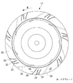
本実施形態では、かかる構成のターボファン17において、図3および図4に示されるように、シュラウド29の複数枚のブレード30間におけるシュラウド面に、中心側から外周側に向う複数のスリット状の貫通部32が設けられ、この貫通部32にそれぞれシュラウド29の内面側から裏面側にかけてシュラウド面に対して傾斜角度θを持ったルーバ33が設けられた構成とされている。
In the present embodiment, in the
このルーバ33は、シュラウド29から切り起こされるように該シュラウド29と一体に成形されており、その傾斜角度θは、図4に示されるように、ルーバ33の回転方向上流側端33Aがシュラウド29の内面29A側に入り込み、回転方向下流側端33Bがシュラウド29の裏面29B側に突出される大きさの角度とされている。また、傾斜角度θは、ルーバ33の外周端側において最も大きくされ、外周側から中心側に向って漸次小さくされており、中心側の端部でシュラウド面と同一面とされている。
The
さらに、ルーバ33は、ルーバ33の半径方向に対する傾き角と、シュラウド29外周に対する接線とがなす角度をルーバ取付け角αとしたとき、ブレード30における同様の取付け角βに対して、α>βとされており、図3からも明らかな通り、ルーバ33の方がブレード30よりも半径方向に立っている状態で設けられている。
なお、上記ターボファン17は、樹脂材製であり、主板27とブレード30とを一体で成形し、これに対して別体で成形されたシュラウド29を超音波溶着することによって製造されるものである。
Further, the
The
以上に説明の構成により、本実施形態によれば、以下の作用効果を奏する。
ターボファン17がファンモータ16により駆動され、N方向(図3参照)に回転されると、室内空気は、図2に示す白抜き矢印の如く、吸込グリル23からエアフィルタ22を介して室内機3内に吸込まれ、更にベルマウス13の空気吸込口12からターボファン17の流体流路28へと吸込まれる。この空気流は、ブレード30により昇圧され、ブレード30の高さ方向に沿ってその外周端(後縁)からラジアル方向に吹出された後、熱交換器18で加熱または冷却される。熱交換器18で温度調整された空気は、風路15を経て吹出口20から室内へと吹出され、室内の暖房または冷房に供される。
With the configuration described above, according to the present embodiment, the following operational effects can be obtained.
When the
上記室内機3では、ターボファン17の外周を取り囲むように配置されている熱交換器18に対して、その高さ方向の風速分布を均一にして空気流を流通させることが、熱交換器18の全面積を有効活用して熱交換性能を高め、空気調和機1の性能を向上させることに繋がる。そのために、ターボファン17からの吹出風の吹出幅(ブレード30の高さ方向幅)方向の風速分布を均一化し、特にターボファン17のシュラウド29側から吹出される吹出風の風量を増加し、熱交換器18の下方部分に向う風量を如何に増加するかが課題となる。
In the
しかるに、本実施形態にかかるターボファン17は、シュラウド29の複数枚のブレード30間におけるシュラウド面に、それぞれ中心側から外周側に向うスリット状の貫通部32が設けられており、この貫通部32にシュラウド29の内面29A側から裏面29B側にかけてシュラウド面に対して傾斜角度θを持ったルーバ33が設けられた構成とされている。このルーバ33は、軸流ファンとしての役割を担い、図5(A)に示されるように、シュラウド29の内面29Aに沿う空気流S1を吸引してその空気流を増加することにより、シュラウド内面29Aでの流れの剥離を抑制することができる。
However, in the
また、ルーバ33の軸流ファン的な作用によって、図5(A)に示されるように、貫通部32を通して一部の空気流S2が遠心力でラジアル方向に吹出される結果、シュラウド29の内面29Aに沿う空気流S1の増加と相俟ってブレード30のシュラウド29側からの吹出風量を増加し、図5(B)に示される従来例に対して、吹出幅方向の風速分布を均一化することができる。
Further, due to the axial fan action of the
その結果、ターボファン17において、シュラウド内面29Aでの剥離抑制による騒音の低減と吹出風の風速分布の均一化を図ることができる。また、これによって、熱交換器18の下方部分への吹出風量を増加して熱交換性能を高め、空気調和機1の能力向上および低騒音化を図ることができる。同時に、ルーバ33から吹出されるラジアル方向への吹出風(空気流S2)によって、ベルマウス13とシュラウド29との間の再循環路31への再循環流S3を抑え込み、その流量を低減して適正量にコントロールできるため、シュラウド29の内面29Aでの剥離抑制に寄与させながら、無駄な動力消費やNZ音等の異音発生をも抑制することができる。
As a result, in the
また、ルーバ33は、スリット状の貫通部32内にシュラウド29と一体成形されることにより設けられているため、シュラウド29の成形時に、シュラウド面にスリット状の貫通部32およびルーバ33を同時に一体成形することができる。従って、部品数や組み立て工数の増加を抑えることができ、騒音低減や風速分布の改善対策での重量増加やコストアップ要因を排除することができる。
Further, since the
また、ルーバ33は、傾斜角度θが該ルーバ33の回転方向上流側端33Aがシュラウド29の内面29A側に入り込み、回転方向下流側端33Bがシュラウド29の裏面29B側に突出される大きさの角度θとされている。このため、ルーバ33のシュラウド内面29A側に入り込んでいる回転方向上流側端33Aによってシュラウド内面29Aに沿う空気流S1を確実に貫通部32に誘引(図4(A)の矢印S4)し、その流れをシュラウド裏面29B側に突出されている回転方向下流側端33Bの遠心作用によってラジアル方向に空気流S2の如く吹出すことができる。従って、シュラウド内面29Aに沿う空気流S1を増加し、シュラウド内面29A側での流れの剥離を確実に抑制することができるとともに、シュラウド29側からの吹出風量を増加し、吹出幅方向の風速分布を均一化することができる。
Further, the
また、ルーバ33の傾斜角度θは、外周端側が最も大きく、中心側に向うに従い漸次小さくされているため、周方向速度が速くなる外周端側での傾斜角度θを最も大きくすることによって、シュラウド内面29Aに沿う空気流S1を効率的に貫通部32に誘引(図4(A)の矢印S4)し、図5(A)に示されるように、シュラウド裏面29B側より遠心作用でラジアル方向に空気流S2の如く吹出すことができる。従って、ルーバ33による剥離抑制および風速分布の均一化効果を最大限発揮させることができるとともに、シュラウド29との一体成形をし易くすることができる。
Further, the inclination angle θ of the
さらに、本実施形態では、ルーバ33の取付け角αが、ブレード30の取付け角βよりも大きく、α>βとされており、ブレード30の負圧面側に沿う空気流を取付け角αが大きくされているルーバ33により掬いあげるようにして貫通部32に効果的に誘引(図4(A)の矢印S4)することができる。このため、シュラウド29の内面29A側に沿う空気流S1を増加し、シュラウド内面29Aでの流れの剥離を抑制することができるとともに、吹出幅方向の風速分布を均一化することができる。
Furthermore, in this embodiment, the mounting angle α of the
[第2実施形態]
次に、本発明の第2実施形態について、図6を用いて説明する。
本実施形態は、上記した第1実施形態に対して、ルーバ33を翼型断面形状としている点が異なる。その他の点については、第1実施形態と同様であるので説明は省略する。
本実施形態においては、シュラウド29の貫通部32に設けられているルーバ33の断面形状が、図6に示されるように、翼型形状33Cとされている。
このように、ルーバ33の断面形状を翼型形状33Cとすることによって、ルーバ33自身による回転時の風切り音を低減することができる。このため、ターボファン17の一層の低騒音化を図ることができる。
[Second Embodiment]
Next, a second embodiment of the present invention will be described with reference to FIG.
This embodiment is different from the first embodiment described above in that the
In this embodiment, the cross-sectional shape of the
Thus, by setting the cross-sectional shape of the
[第3実施形態]
次に、本発明の第3実施形態について、図7を用いて説明する。
本実施形態は、上記した第1および第2実施形態に対して、複数枚のブレード30間に設けられているルーバ33と各ブレード30との間の距離γが不揃いとされている点が異なる。その他の点については、第1,第2実施形態と同様であるので説明は省略する。
本実施形態においては、図7に示されるように、複数枚のブレード30間において、シュラウド29の貫通部32に設けられている各ルーバ33と各ブレード30との間の距離γが、それぞれγ1≠γ2≠・・・γNとされ、各ブレード30間において不揃いとされている。
[Third Embodiment]
Next, a third embodiment of the present invention will be described with reference to FIG.
This embodiment is different from the first and second embodiments described above in that the distance γ between the
In the present embodiment, as shown in FIG. 7, the distance γ between each
このように、各ルーバ33と各ブレード30との間の距離γを、各ブレード30間において不揃いとすることによって、ブレード30間毎に流れのパターンを変化させることができる。このため、ブレード30を不等ピッチにした場合と同様、N/60×Z(N;回転数、Z;ブレード枚数の周波数音)で表されるNZ音を低減することができ、ターボファン17の更なる低騒音化を図ることができる。
Thus, by making the distances γ between the
[第4実施形態]
次に、本発明の第4実施形態について、図8および図9を用いて説明する。
本実施形態は、上記した第1ないし第3実施形態に対して、貫通部32の回転方向下流側におけるシュラウド裏面29Bに、サブブレード34を設けている点が異なる。その他の点については、第1ないし第3実施形態と同様であるので説明は省略する。
本実施形態においては、図8、図9に示されるように、シュラウド29の複数枚のブレード30間において、スリット状貫通部32の回転方向下流側におけるシュラウド裏面29Bに、軸方向に立設されたサブブレード34が設けられた構成とされている。
[Fourth Embodiment]
Next, a fourth embodiment of the present invention will be described with reference to FIGS.
This embodiment is different from the first to third embodiments described above in that a
In this embodiment, as shown in FIGS. 8 and 9, between the plurality of
上記したように、スリット状貫通部32の回転方向下流側におけるシュラウド裏面29Bに、サブブレード34を立設した構成とすることにより、ルーバ33により貫通部32に誘引された空気流S4に対し、更にサブブレード34によってラジアル方向の速度成分を与えることができる。これによって、再循環流S3を抑え、その流量を更に低減して無駄な動力消費や異音の発生を抑制することができるとともに、吹出幅方向の風速分布をより均一化することができる。
As described above, by adopting a configuration in which the sub-blade 34 is erected on the shroud back
なお、本発明は、上記実施形態にかかる発明に限定されるものではなく、その要旨を逸脱しない範囲において、適宜変形が可能である。例えば、上記実施形態では、複数枚のブレード30間において、スリット状貫通部32およびルーバ33を1組設けた例について説明したが、各ブレード30間に、スリット状貫通部32およびルーバ33を複数組設けた構成としてもよい。
In addition, this invention is not limited to the invention concerning the said embodiment, In the range which does not deviate from the summary, it can change suitably. For example, in the above-described embodiment, an example in which one set of slit-like through
また、空気調和機1としては、図1に示される天井埋込み型空気調和機1に限らず、床置き型空気調和機等、他形式の空気調和機にも同様に適用することができることはもちろんである。さらに、ターボファン17については、空気調和機以外の用途にも適用できることは云うまでもない。
Further, the
1 天井埋込み型空気調和機
12 空気吸込口
13 ベルマウス
17 ターボファン
18 熱交換器
26 ハブ
27 主板
28 流体流路
29 シュラウド
29A シュラウドの内面
29B シュラウドの裏面
30 ブレード
32 スリット状の貫通部
33 ルーバ
33A ルーバの回転方向上流側端
33B ルーバの回転方向下流側端
33C 翼型形状
34 サブブレード
θ ルーバの傾斜角度
α ルーバの取付け角
β ブレードの取付け角
γ1,γ2 ルーバとブレード間の距離
DESCRIPTION OF
Claims (12)
前記シュラウドの前記複数枚のブレード間におけるシュラウド面に、中心側から外周側に向うスリット状の貫通部が設けられ、該貫通部に前記シュラウドの内面側から裏面側にかけて前記シュラウド面に対して傾斜角度を持ち、前記シュラウドの内面側から空気流を誘引して裏面側のラジアル方向に吹出すルーバが設けられていることを特徴とするターボファン。 A main plate provided with a hub for fixing the rotation shaft at the center, a shroud forming a fluid flow path disposed opposite to the main plate, and a plurality of plates disposed between the shroud and the main plate In a turbofan with a single blade,
The shroud surface between the plurality of blades of the shroud is provided with a slit-like through portion from the center side toward the outer peripheral side, and the through portion is inclined with respect to the shroud surface from the inner surface side to the back surface side of the shroud. Chi lifting angle, turbofan, characterized in that to attract the air flow louvers blown in the radial direction of the back side are provided from the inner surface side of the shroud.
The air conditioner according to claim 10 or 11, wherein a heat exchanger is disposed on an outer peripheral side of the turbo fan so as to surround the turbo fan.
Priority Applications (1)
| Application Number | Priority Date | Filing Date | Title |
|---|---|---|---|
| JP2010139301A JP5574841B2 (en) | 2010-06-18 | 2010-06-18 | Turbofan and air conditioner using the same |
Applications Claiming Priority (1)
| Application Number | Priority Date | Filing Date | Title |
|---|---|---|---|
| JP2010139301A JP5574841B2 (en) | 2010-06-18 | 2010-06-18 | Turbofan and air conditioner using the same |
Publications (2)
| Publication Number | Publication Date |
|---|---|
| JP2012002165A JP2012002165A (en) | 2012-01-05 |
| JP5574841B2 true JP5574841B2 (en) | 2014-08-20 |
Family
ID=45534419
Family Applications (1)
| Application Number | Title | Priority Date | Filing Date |
|---|---|---|---|
| JP2010139301A Active JP5574841B2 (en) | 2010-06-18 | 2010-06-18 | Turbofan and air conditioner using the same |
Country Status (1)
| Country | Link |
|---|---|
| JP (1) | JP5574841B2 (en) |
Families Citing this family (4)
| Publication number | Priority date | Publication date | Assignee | Title |
|---|---|---|---|---|
| JPWO2016013096A1 (en) * | 2014-07-25 | 2017-04-27 | ジョンソンコントロールズ ヒタチ エア コンディショニング テクノロジー(ホンコン)リミテッド | Blower and air conditioner |
| JP6369684B2 (en) | 2014-10-10 | 2018-08-08 | 株式会社富士通ゼネラル | Embedded ceiling air conditioner |
| JP6554790B2 (en) * | 2014-12-15 | 2019-08-07 | 日本電産株式会社 | Fan device |
| CN111845995A (en) * | 2020-08-28 | 2020-10-30 | 广东省智能制造研究所 | Low-noise negative-pressure wall-climbing robot |
Family Cites Families (5)
| Publication number | Priority date | Publication date | Assignee | Title |
|---|---|---|---|---|
| JPS5777846A (en) * | 1980-10-30 | 1982-05-15 | Matsushita Electric Works Ltd | Manufacture of louver |
| JPH02119998U (en) * | 1989-03-15 | 1990-09-27 | ||
| JP3371861B2 (en) * | 1999-08-25 | 2003-01-27 | ダイキン工業株式会社 | Centrifugal blower and air conditioner provided with the centrifugal blower |
| JP2007040617A (en) * | 2005-08-03 | 2007-02-15 | Hitachi Ltd | Air conditioning indoor unit |
| JP4816045B2 (en) * | 2005-12-09 | 2011-11-16 | 株式会社富士通ゼネラル | Turbofan and air conditioner using the same |
-
2010
- 2010-06-18 JP JP2010139301A patent/JP5574841B2/en active Active
Also Published As
| Publication number | Publication date |
|---|---|
| JP2012002165A (en) | 2012-01-05 |
Similar Documents
| Publication | Publication Date | Title |
|---|---|---|
| WO2009139422A1 (en) | Centrifugal fan | |
| JP6324316B2 (en) | Air conditioner indoor unit | |
| CN110325745B (en) | Propeller fan, blower, and air conditioner | |
| JP2007170331A (en) | Turbofan and indoor unit of air conditioner using it | |
| JP2010078274A (en) | Indoor unit for floor setting type air conditioner | |
| WO2016071948A1 (en) | Propeller fan, propeller fan device, and outdoor equipment for air-conditioning device | |
| JP5574841B2 (en) | Turbofan and air conditioner using the same | |
| KR20080054153A (en) | Turbo fan and air-conditioner having the same | |
| JP6120203B2 (en) | Centrifugal blower | |
| JP2007205268A (en) | Centrifugal fan | |
| JP4644903B2 (en) | Centrifugal turbo air machine impeller, centrifugal turbo air machine, and air conditioner | |
| WO2018029877A1 (en) | Indoor unit and air-conditioning device | |
| JP2007040617A (en) | Air conditioning indoor unit | |
| JP2007154685A (en) | Turbo fan and air conditioner using the same | |
| JP2004353510A (en) | Centrifugal fan, and air-conditioner having the same | |
| JP6135125B2 (en) | Indoor unit | |
| JP2016160905A (en) | Centrifugal fan | |
| JP2016188578A (en) | Air blower | |
| JP7086229B2 (en) | Blower, indoor unit and air conditioner | |
| JP2007051790A (en) | Air-conditioning indoor unit | |
| WO2018029878A1 (en) | Indoor unit and air-conditioning device | |
| JP6615379B2 (en) | Propeller fan, outdoor unit and refrigeration cycle equipment | |
| JP2007170771A (en) | Turbofan and indoor unit of air conditioner using the same | |
| AU2018402616B2 (en) | Air conditioner | |
| KR101468739B1 (en) | Air conditioner and Fan assembly thereof |
Legal Events
| Date | Code | Title | Description |
|---|---|---|---|
| A621 | Written request for application examination |
Free format text: JAPANESE INTERMEDIATE CODE: A621 Effective date: 20130522 |
|
| A977 | Report on retrieval |
Free format text: JAPANESE INTERMEDIATE CODE: A971007 Effective date: 20140129 |
|
| A131 | Notification of reasons for refusal |
Free format text: JAPANESE INTERMEDIATE CODE: A131 Effective date: 20140204 |
|
| A521 | Written amendment |
Free format text: JAPANESE INTERMEDIATE CODE: A523 Effective date: 20140407 |
|
| TRDD | Decision of grant or rejection written | ||
| A01 | Written decision to grant a patent or to grant a registration (utility model) |
Free format text: JAPANESE INTERMEDIATE CODE: A01 Effective date: 20140603 |
|
| A61 | First payment of annual fees (during grant procedure) |
Free format text: JAPANESE INTERMEDIATE CODE: A61 Effective date: 20140701 |
|
| R151 | Written notification of patent or utility model registration |
Ref document number: 5574841 Country of ref document: JP Free format text: JAPANESE INTERMEDIATE CODE: R151 |
|
| R250 | Receipt of annual fees |
Free format text: JAPANESE INTERMEDIATE CODE: R250 |