JP5572974B2 - Manufacturing method of solid secondary battery - Google Patents
Manufacturing method of solid secondary battery Download PDFInfo
- Publication number
- JP5572974B2 JP5572974B2 JP2009071814A JP2009071814A JP5572974B2 JP 5572974 B2 JP5572974 B2 JP 5572974B2 JP 2009071814 A JP2009071814 A JP 2009071814A JP 2009071814 A JP2009071814 A JP 2009071814A JP 5572974 B2 JP5572974 B2 JP 5572974B2
- Authority
- JP
- Japan
- Prior art keywords
- active material
- holes
- material layer
- solid electrolyte
- secondary battery
- Prior art date
- Legal status (The legal status is an assumption and is not a legal conclusion. Google has not performed a legal analysis and makes no representation as to the accuracy of the status listed.)
- Expired - Fee Related
Links
- 239000007787 solid Substances 0.000 title claims description 62
- 238000004519 manufacturing process Methods 0.000 title claims description 48
- 239000011149 active material Substances 0.000 claims description 167
- 239000007784 solid electrolyte Substances 0.000 claims description 114
- 238000000034 method Methods 0.000 claims description 90
- 239000011344 liquid material Substances 0.000 claims description 26
- 238000010438 heat treatment Methods 0.000 claims description 14
- 238000003980 solgel method Methods 0.000 claims description 11
- 239000011347 resin Substances 0.000 claims description 8
- 229920005989 resin Polymers 0.000 claims description 8
- 238000007740 vapor deposition Methods 0.000 claims description 6
- 239000007774 positive electrode material Substances 0.000 description 33
- 239000007773 negative electrode material Substances 0.000 description 31
- 239000010409 thin film Substances 0.000 description 31
- QTBSBXVTEAMEQO-UHFFFAOYSA-N Acetic acid Chemical compound CC(O)=O QTBSBXVTEAMEQO-UHFFFAOYSA-N 0.000 description 18
- KFZMGEQAYNKOFK-UHFFFAOYSA-N Isopropanol Chemical compound CC(C)O KFZMGEQAYNKOFK-UHFFFAOYSA-N 0.000 description 18
- WMFOQBRAJBCJND-UHFFFAOYSA-M Lithium hydroxide Chemical compound [Li+].[OH-] WMFOQBRAJBCJND-UHFFFAOYSA-M 0.000 description 18
- OKKJLVBELUTLKV-UHFFFAOYSA-N Methanol Chemical compound OC OKKJLVBELUTLKV-UHFFFAOYSA-N 0.000 description 18
- WHXSMMKQMYFTQS-UHFFFAOYSA-N Lithium Chemical compound [Li] WHXSMMKQMYFTQS-UHFFFAOYSA-N 0.000 description 13
- 229910052744 lithium Inorganic materials 0.000 description 13
- LFQSCWFLJHTTHZ-UHFFFAOYSA-N Ethanol Chemical compound CCO LFQSCWFLJHTTHZ-UHFFFAOYSA-N 0.000 description 12
- 239000000463 material Substances 0.000 description 11
- 239000007788 liquid Substances 0.000 description 7
- XIXADJRWDQXREU-UHFFFAOYSA-M lithium acetate Chemical compound [Li+].CC([O-])=O XIXADJRWDQXREU-UHFFFAOYSA-M 0.000 description 6
- 229920003229 poly(methyl methacrylate) Polymers 0.000 description 6
- 239000004926 polymethyl methacrylate Substances 0.000 description 6
- 239000002994 raw material Substances 0.000 description 6
- RTAQQCXQSZGOHL-UHFFFAOYSA-N Titanium Chemical compound [Ti] RTAQQCXQSZGOHL-UHFFFAOYSA-N 0.000 description 5
- 229910052751 metal Inorganic materials 0.000 description 5
- 239000002184 metal Substances 0.000 description 5
- 239000000843 powder Substances 0.000 description 5
- 238000004904 shortening Methods 0.000 description 5
- 238000005229 chemical vapour deposition Methods 0.000 description 3
- KRKNYBCHXYNGOX-UHFFFAOYSA-N citric acid Chemical compound OC(=O)CC(O)(C(O)=O)CC(O)=O KRKNYBCHXYNGOX-UHFFFAOYSA-N 0.000 description 3
- QHGJSLXSVXVKHZ-UHFFFAOYSA-N dilithium;dioxido(dioxo)manganese Chemical compound [Li+].[Li+].[O-][Mn]([O-])(=O)=O QHGJSLXSVXVKHZ-UHFFFAOYSA-N 0.000 description 3
- 230000005469 synchrotron radiation Effects 0.000 description 3
- VXUYXOFXAQZZMF-UHFFFAOYSA-N titanium(IV) isopropoxide Chemical compound CC(C)O[Ti](OC(C)C)(OC(C)C)OC(C)C VXUYXOFXAQZZMF-UHFFFAOYSA-N 0.000 description 3
- 229910020731 Li0.35La0.55TiO3 Inorganic materials 0.000 description 2
- 229910012851 LiCoO 2 Inorganic materials 0.000 description 2
- 229910015643 LiMn 2 O 4 Inorganic materials 0.000 description 2
- 229910013290 LiNiO 2 Inorganic materials 0.000 description 2
- HBBGRARXTFLTSG-UHFFFAOYSA-N Lithium ion Chemical compound [Li+] HBBGRARXTFLTSG-UHFFFAOYSA-N 0.000 description 2
- PXHVJJICTQNCMI-UHFFFAOYSA-N Nickel Chemical compound [Ni] PXHVJJICTQNCMI-UHFFFAOYSA-N 0.000 description 2
- 239000006096 absorbing agent Substances 0.000 description 2
- 230000000694 effects Effects 0.000 description 2
- 239000007772 electrode material Substances 0.000 description 2
- 238000005323 electroforming Methods 0.000 description 2
- 239000003792 electrolyte Substances 0.000 description 2
- 150000002500 ions Chemical class 0.000 description 2
- 229910001416 lithium ion Inorganic materials 0.000 description 2
- 230000008018 melting Effects 0.000 description 2
- 238000002844 melting Methods 0.000 description 2
- 238000000465 moulding Methods 0.000 description 2
- 239000005486 organic electrolyte Substances 0.000 description 2
- 238000007086 side reaction Methods 0.000 description 2
- ATJFFYVFTNAWJD-UHFFFAOYSA-N Tin Chemical compound [Sn] ATJFFYVFTNAWJD-UHFFFAOYSA-N 0.000 description 1
- 238000001015 X-ray lithography Methods 0.000 description 1
- MQRWBMAEBQOWAF-UHFFFAOYSA-N acetic acid;nickel Chemical compound [Ni].CC(O)=O.CC(O)=O MQRWBMAEBQOWAF-UHFFFAOYSA-N 0.000 description 1
- 238000006243 chemical reaction Methods 0.000 description 1
- 229940011182 cobalt acetate Drugs 0.000 description 1
- QAHREYKOYSIQPH-UHFFFAOYSA-L cobalt(II) acetate Chemical compound [Co+2].CC([O-])=O.CC([O-])=O QAHREYKOYSIQPH-UHFFFAOYSA-L 0.000 description 1
- 239000010408 film Substances 0.000 description 1
- 229910052738 indium Inorganic materials 0.000 description 1
- APFVFJFRJDLVQX-UHFFFAOYSA-N indium atom Chemical compound [In] APFVFJFRJDLVQX-UHFFFAOYSA-N 0.000 description 1
- 238000010030 laminating Methods 0.000 description 1
- JLRJWBUSTKIQQH-UHFFFAOYSA-K lanthanum(3+);triacetate Chemical compound [La+3].CC([O-])=O.CC([O-])=O.CC([O-])=O JLRJWBUSTKIQQH-UHFFFAOYSA-K 0.000 description 1
- 229940071125 manganese acetate Drugs 0.000 description 1
- UOGMEBQRZBEZQT-UHFFFAOYSA-L manganese(2+);diacetate Chemical compound [Mn+2].CC([O-])=O.CC([O-])=O UOGMEBQRZBEZQT-UHFFFAOYSA-L 0.000 description 1
- 229910052759 nickel Inorganic materials 0.000 description 1
- 229940078494 nickel acetate Drugs 0.000 description 1
- 238000007747 plating Methods 0.000 description 1
- 229920000642 polymer Polymers 0.000 description 1
- 238000007789 sealing Methods 0.000 description 1
- 238000000926 separation method Methods 0.000 description 1
- 238000004544 sputter deposition Methods 0.000 description 1
- 239000000758 substrate Substances 0.000 description 1
- 238000007736 thin film deposition technique Methods 0.000 description 1
- 229910052718 tin Inorganic materials 0.000 description 1
- 239000012808 vapor phase Substances 0.000 description 1
- 229910000634 wood's metal Inorganic materials 0.000 description 1
Images


Classifications
-
- Y—GENERAL TAGGING OF NEW TECHNOLOGICAL DEVELOPMENTS; GENERAL TAGGING OF CROSS-SECTIONAL TECHNOLOGIES SPANNING OVER SEVERAL SECTIONS OF THE IPC; TECHNICAL SUBJECTS COVERED BY FORMER USPC CROSS-REFERENCE ART COLLECTIONS [XRACs] AND DIGESTS
- Y02—TECHNOLOGIES OR APPLICATIONS FOR MITIGATION OR ADAPTATION AGAINST CLIMATE CHANGE
- Y02E—REDUCTION OF GREENHOUSE GAS [GHG] EMISSIONS, RELATED TO ENERGY GENERATION, TRANSMISSION OR DISTRIBUTION
- Y02E60/00—Enabling technologies; Technologies with a potential or indirect contribution to GHG emissions mitigation
- Y02E60/10—Energy storage using batteries
-
- Y—GENERAL TAGGING OF NEW TECHNOLOGICAL DEVELOPMENTS; GENERAL TAGGING OF CROSS-SECTIONAL TECHNOLOGIES SPANNING OVER SEVERAL SECTIONS OF THE IPC; TECHNICAL SUBJECTS COVERED BY FORMER USPC CROSS-REFERENCE ART COLLECTIONS [XRACs] AND DIGESTS
- Y02—TECHNOLOGIES OR APPLICATIONS FOR MITIGATION OR ADAPTATION AGAINST CLIMATE CHANGE
- Y02P—CLIMATE CHANGE MITIGATION TECHNOLOGIES IN THE PRODUCTION OR PROCESSING OF GOODS
- Y02P70/00—Climate change mitigation technologies in the production process for final industrial or consumer products
- Y02P70/50—Manufacturing or production processes characterised by the final manufactured product
Landscapes
- Moulds For Moulding Plastics Or The Like (AREA)
- Secondary Cells (AREA)
- Battery Electrode And Active Subsutance (AREA)
Description
本発明は、固体二次電池の製造方法に関するものである。 The present invention relates to a manufacturing method of the solid-body rechargeable battery.
携帯電話機やモバイルコンピューター等の電源として、繰り返し充電が可能な二次電池の開発が進められている。このような二次電池の中には、有機電解液を用いたものが知られているが、有機電解液を用いた二次電池は、副反応が多く、また、液漏れや発火の危険性があり、安全面への配慮が必要とされていた。 Development of a secondary battery that can be repeatedly charged as a power source for a mobile phone or a mobile computer has been underway. Among these secondary batteries, those using organic electrolytes are known, but secondary batteries using organic electrolytes have many side reactions, and there is a risk of liquid leakage and ignition. There was a need for safety considerations.
脱電解液化の試みとして、固体電解質を用いた二次電池(固体二次電池)が報告されている(例えば、特許文献1,2)。例えば、固体電解質を用いたリチウムイオン二次電池の場合、電池反応によって電解質中を移動するイオンがリチウムイオンだけになるので、副反応が殆どなく、可燃性の有機溶液を含まず、さらに、液封止構造が必要ないので、小型・薄型化が可能となる。 A secondary battery using a solid electrolyte (solid secondary battery) has been reported as an attempt to remove the electrolyte (for example, Patent Documents 1 and 2). For example, in the case of a lithium ion secondary battery using a solid electrolyte, the ions that move in the electrolyte by the battery reaction are only lithium ions, so there are almost no side reactions, no flammable organic solution is contained, Since a sealing structure is not required, it is possible to reduce the size and thickness.
しかしながら、特許文献1の固体二次電池のように、固体電解質粉を電極活物質粉とともに圧粉成形する方法では、固体電解質粉と電極活物質粉との界面や固体電解質粉同士の界面で界面接触が不十分となり、高い電池出力が得られいという問題があった。また、充放電サイクルに伴う体積変化によって界面接触が不安定になり、サイクル寿命が劣化するという問題もあった。 However, in the method of compacting the solid electrolyte powder together with the electrode active material powder as in the solid secondary battery of Patent Document 1, the interface between the solid electrolyte powder and the electrode active material powder or the interface between the solid electrolyte powders is an interface. There was a problem that contact was insufficient and high battery output could not be obtained. In addition, there is a problem that the interface contact becomes unstable due to the volume change accompanying the charge / discharge cycle, and the cycle life is deteriorated.
一方、特許文献2の固体二次電池のように、スパッタリングなどの気相薄膜堆積法を用いて正極薄膜と固体電解質薄膜と負極薄膜とを順次積層するものも報告されている。このように薄膜を積層する方法では、電極と固体電解質との界面接触が良好であり、且つ、活物質層や固体電解質層の厚さを小さくすることができるので、高い電池出力と良好なサイクル寿命特性が得られる。
On the other hand, as in the solid secondary battery of
しかしながら、この方法では、各層の膜厚が小さくなるので、単位面積当たりの活物質層の総厚が小さくなり、容量の大きな二次電池を提供することができなかった。 However, in this method, since the film thickness of each layer is small, the total thickness of the active material layer per unit area is small, and a secondary battery having a large capacity cannot be provided.
本発明はこのような事情に鑑みてなされたものであって、高出力で大容量な固体二次電池及びその製造方法を提供することを目的とする。 This invention is made | formed in view of such a situation, Comprising: It aims at providing the high output and large capacity solid secondary battery, and its manufacturing method.
上記の課題を解決するため、本発明は、固体二次電池であって、複数の穴が形成された第1活物質層と、前記複数の穴の内部に形成された固体電解質層と、前記固体電解質層に接して形成された第2活物質層と、を備え、前記第1活物質層と前記第2活物質層との間に前記固体電解質層を有することを特徴とする固体二次電池である。
前記複数の穴は複数の縦穴であり、前記固体電解質層は前記複数の縦穴の底面及び内壁面に接して形成され、前記第1活物質層及び前記第2活物質層の一方は前記固体二次電池の正極側の活物質として機能し、前記第1活物質層及び前記第2活物質層の他方は前記固体二次電池の負極側の活物質として機能し、前記第1活物質層と前記第2活物質層とは接しないこととしてもよい。
前記第2活物質層は、前記固体電解質層を介して、前記複数の穴の各々の内部を埋めるように充填されていてもよい。
前記第1活物質層と平行な面内における互いに直交する2方向をX方向およびY方向とし、前記X方向および前記Y方向と直交する方向をZ方向としたときに、前記複数の穴は前記X方向と前記Y方向にそれぞれ一定の間隔で周期的に配置され、前記Z方向から見た前記複数の穴の各々の平面形状は円形であり、前記複数の穴の直径は互いに等しく、前記複数の穴の配置間隔は、前記穴の直径の1.5〜2倍であってもよい。
本発明は、固体二次電池であって、複数の第1の穴と複数の第2の穴とを有する固体電解質層と、前記複数の第1の穴の内部に形成された第1活物質層と、前記複数の第2の穴の内部に形成された第2活物質層と、を備え、前記複数の第1の穴のいずれかと前記複数の第2の穴のいずれかとは前記固体電解質層を介して配置されていることを特徴とする固体二次電池である。
前記複数の第1の穴は複数の縦穴であり、前記複数の第2の穴は複数の縦穴であり、前記第1活物質層は、前記複数の第1の穴の表面に接して形成され、前記第2活物質層は、前記複数の第2の穴の表面に接して形成され、前記第1活物質層及び前記第2活物質層のうちの一方は前記固体二次電池の正極側の活物質として機能し、前記第1活物質層及び前記第2活物質層のうちの他方は負極側の活物質として機能し、前記複数の第1の穴のいずれかと前記複数の第2の穴のいずれかとは、前記固体電解質層を介して隣りあうように配置されていてもよい。
前記第1活物質層は、前記複数の第1の穴の各々の内部全体に充填され、前記第2活物質層は、前記複数の第2の穴の各々の内部全体に充填されていてもよい。
前記複数の第1の穴の各々と前記複数の第2の穴の各々とが交互に、かつ、周期的に配置されていてもよい。
前記固体電解質層と平行な面内における互いに直交する2方向をX方向およびY方向とし、前記X方向および前記Y方向と直交する方向をZ方向としたときに、前記複数の第1の穴および前記複数の第2の穴を含む複数の穴は前記X方向と前記Y方向にそれぞれ一定の間隔で周期的に配置され、前記Z方向から見た前記複数の穴の各々の平面形状は円形であり、前記複数の穴の直径は互いに等しく、前記複数の穴の配置間隔は、前記穴の直径の1.5〜2倍であってもよい。
本発明は、固体二次電池の製造方法であって、複数の穴を有する第1活物質層を形成する第1の工程と、前記複数の穴の表面及び前記第1活物質層の表面に固体電解質層を形成する第2の工程と、前記固体電解質層の表面に第2活物質層を形成する第3の工程と、を備え、前記第1の工程は、表面に複数の突起が形成された成形型に、前記第1活物質層を形成するための第1の液体材料を塗布する第1の副工程と、前記第1の液体材料を固化し、前記第1活物質層とする第2の副工程と、前記第1活物質層と前記成形型とを分離する第3の副工程と、を含むことを特徴とする固体二次電池の製造方法である。
前記第1活物質層及び前記第2活物質層のうち一方は正極側の活物質として機能し、前記第1活物質層及び前記第2活物質層のうち他方は負極側の活物質として機能し、前記複数の穴は複数の縦穴であってもよい。
前記成形型は、LIGA(Lithographie Galvanoformung Abformung)法を用いて形成されたものであってもよい。
前記第2の副工程に熱処理を行う工程を含み、前記成形型を樹脂で形成し、前記熱処理で前記成形型を焼散させることで、前記第2の副工程と前記第3の副工程とを1つの工程として行ってもよい。
前記第2の工程において、前記固体電解質層は、気相堆積法又はゾルゲル法によって形成されてもよい。
前記第3の工程は、前記第2活物質層を形成するための第2の液体材料を、前記固体電解質薄層の表面に塗布する第4の副工程を含んでもよい。
前記固体電解質層は前記複数の縦穴の底面及び内壁面に接して形成されていてもよい。
前記第2活物質層は、前記固体電解質層を介して、前記複数の穴の各々の内部を埋めるように充填されていてもよい。
前記第1活物質層と平行な面内における互いに直交する2方向をX方向およびY方向とし、前記X方向および前記Y方向と直交する方向をZ方向としたときに、前記複数の穴は前記X方向と前記Y方向にそれぞれ一定の間隔で周期的に配置され、前記Z方向から見た前記複数の穴の各々の平面形状は円形であり、前記複数の穴の直径は互いに等しく、前記複数の穴の配置間隔は、前記穴の直径の1.5〜2倍であってもよい。
本発明は、固体二次電池の製造方法であって、複数の第1の穴及び複数の第2の穴が形成された固体電解質層を形成する第1の工程と、前記複数の第1の穴の内部に第1活物質層を形成する第2の工程と、前記複数の第2の穴の内部に第2活物質層を形成する第3の工程と、を備え、前記第1の工程は、表面に複数の突起が形成された成形型に前記固体電解質層の第1の液体材料を塗布する第1の副工程と、前記第1の液体材料を固化し、前記固体電解質層とする第2の副工程と、前記固体電解質層と前記成形型とを分離する第3の副工程と、を含み、前記複数の第1の穴のいずれかと前記複数の第2の穴のいずれかとは前記固体電解質層を介して配置されていることを特徴とする固体二次電池の製造方法である。
前記第1活物質層及び前記第2活物質層のうちの一方は正極側の活物質として機能し、前記第1活物質層及び前記第2活物質層のうちの他方は負極側の活物質として機能し、前記複数の第1の穴の各々は縦穴であり、前記複数の第2の穴の各々は縦穴であり、前記第2の工程は、前記複数の第1の穴の表面に接するように前記第1活物質層を形成し、前記第3の工程は、前記複数の第2の穴の表面に接するように前記第2活物質層を形成し、前記複数の第1の穴のいずれかと前記複数の第2の穴のいずれかとが前記固体電解質層を介して隣りあうように配置されてもよい。
前記成形型は、LIGA(Lithographie Galvanoformung Abformung)法を用いて形成されたものであってもよい。
前記第2の副工程に熱処理を行う工程を含み、前記成形型を樹脂で形成し、前記熱処理で前記成形型を焼散させることで、前記第2の副工程と前記第3の副工程を1つの工程として行ってもよい。
前記第2の工程は、前記第1活物質層を形成する液体材料を前記第1の穴の内部に充填する第4の副工程を含み、前記第3の工程は、前記第2活物質層を形成する液体材料を前記第2の穴の内部に充填する第5の副工程を含んでもよい。
前記第4の副工程及び前記第5の副工程において、インクジェット法を用いてもよい。
前記第1活物質層は、前記複数の第1の穴の各々の内部全体に充填され、前記第2活物質層は、前記複数の第2の穴の各々の内部全体に充填されていてもよい。
前記複数の第1の穴の各々と前記複数の第2の穴の各々とが交互に、かつ、周期的に配置されていてもよい。
前記固体電解質層と平行な面内における互いに直交する2方向をX方向およびY方向とし、前記X方向および前記Y方向と直交する方向をZ方向としたときに、前記複数の第1の穴および前記複数の第2の穴を含む複数の穴は前記X方向と前記Y方向にそれぞれ一定の間隔で周期的に配置され、前記Z方向から見た前記複数の穴の各々の平面形状は円形であり、前記複数の穴の直径は互いに等しく、前記複数の穴の配置間隔は、前記穴の直径の1.5〜2倍であってもよい。
本発明の第1の形態の固体二次電池は、一面上に複数の縦穴が形成された第1活物質層と、前記第1活物質層に形成された複数の前記縦穴の底面及び内壁面に接して形成された固体電解質層と、前記固体電解質層に接して形成された第2活物質層と、を備え、前記第1活物質層及び前記第2活物質層のいずれか一方は前記固体二次電池の正極側の活物質として機能し、いずれか他方は負極側の活物質として機能し、前記第1活物質層と前記第2活物質層とは接することなく、前記1活物質層と前記第2活物質層との間に前記固体電解質層を有することを特徴とする。
In order to solve the above problems, the present invention is a solid secondary battery, wherein a first active material layer in which a plurality of holes are formed, a solid electrolyte layer formed in the plurality of holes, A second active material layer formed in contact with the solid electrolyte layer, and having the solid electrolyte layer between the first active material layer and the second active material layer It is a battery.
The plurality of holes are a plurality of vertical holes, the solid electrolyte layer is formed in contact with a bottom surface and an inner wall surface of the plurality of vertical holes, and one of the first active material layer and the second active material layer is the solid second layer. The second active material layer functions as an active material on the positive electrode side of the secondary battery, and the other of the first active material layer and the second active material layer functions as an active material on the negative electrode side of the solid secondary battery, It is good also as not contacting the said 2nd active material layer.
The second active material layer may be filled so as to fill the interior of each of the plurality of holes via the solid electrolyte layer.
When two directions orthogonal to each other in a plane parallel to the first active material layer are defined as an X direction and a Y direction, and a direction orthogonal to the X direction and the Y direction is defined as a Z direction, the plurality of holes are The plurality of holes are periodically arranged in the X direction and the Y direction at regular intervals, the planar shape of each of the plurality of holes viewed from the Z direction is circular, and the diameters of the plurality of holes are equal to each other. The arrangement interval of the holes may be 1.5 to 2 times the diameter of the holes.
The present invention relates to a solid secondary battery, a solid electrolyte layer having a plurality of first holes and a plurality of second holes, and a first active material formed inside the plurality of first holes. And a second active material layer formed inside the plurality of second holes, wherein one of the plurality of first holes and one of the plurality of second holes is the solid electrolyte. It is a solid secondary battery characterized by being arrange | positioned through a layer.
The plurality of first holes are a plurality of vertical holes, the plurality of second holes are a plurality of vertical holes, and the first active material layer is formed in contact with the surfaces of the plurality of first holes. The second active material layer is formed in contact with the surfaces of the plurality of second holes, and one of the first active material layer and the second active material layer is a positive electrode side of the solid secondary battery. The other of the first active material layer and the second active material layer functions as an active material on the negative electrode side, and one of the plurality of first holes and the plurality of second materials. It may be arranged so as to be adjacent to any of the holes with the solid electrolyte layer interposed therebetween.
The first active material layer may fill the entire interior of each of the plurality of first holes, and the second active material layer may fill the entire interior of each of the plurality of second holes. Good.
Each of the plurality of first holes and each of the plurality of second holes may be alternately and periodically arranged.
When the two directions perpendicular to each other in a plane parallel to the solid electrolyte layer are defined as an X direction and a Y direction, and the direction perpendicular to the X direction and the Y direction is defined as a Z direction, the plurality of first holes and The plurality of holes including the plurality of second holes are periodically arranged at regular intervals in the X direction and the Y direction, and the planar shape of each of the plurality of holes viewed from the Z direction is circular. The diameters of the plurality of holes may be equal to each other, and the arrangement interval of the plurality of holes may be 1.5 to 2 times the diameter of the holes.
The present invention is a method for manufacturing a solid secondary battery, wherein a first step of forming a first active material layer having a plurality of holes, a surface of the plurality of holes, and a surface of the first active material layer are provided. A second step of forming a solid electrolyte layer; and a third step of forming a second active material layer on the surface of the solid electrolyte layer, wherein the first step forms a plurality of protrusions on the surface. A first sub-step of applying a first liquid material for forming the first active material layer to the formed mold, and solidifying the first liquid material to form the first active material layer A method for producing a solid secondary battery, comprising: a second sub-step; and a third sub-step for separating the first active material layer and the mold.
One of the first active material layer and the second active material layer functions as an active material on the positive electrode side, and the other of the first active material layer and the second active material layer functions as an active material on the negative electrode side. The plurality of holes may be a plurality of vertical holes.
The mold may be formed using a LIGA (Lithographie Galvanoformung Abformung) method.
The second sub-process includes a step of performing a heat treatment, the mold is formed of resin, and the mold is burned by the heat treatment, whereby the second sub-process and the third sub-process May be performed as one step.
In the second step, the solid electrolyte layer may be formed by a vapor deposition method or a sol-gel method.
The third step may include a fourth sub-step of applying a second liquid material for forming the second active material layer on the surface of the solid electrolyte thin layer.
The solid electrolyte layer may be formed in contact with the bottom surfaces and inner wall surfaces of the plurality of vertical holes.
The second active material layer may be filled so as to fill the interior of each of the plurality of holes via the solid electrolyte layer.
When two directions orthogonal to each other in a plane parallel to the first active material layer are defined as an X direction and a Y direction, and a direction orthogonal to the X direction and the Y direction is defined as a Z direction, the plurality of holes are The plurality of holes are periodically arranged in the X direction and the Y direction at regular intervals, the planar shape of each of the plurality of holes viewed from the Z direction is circular, and the diameters of the plurality of holes are equal to each other. The arrangement interval of the holes may be 1.5 to 2 times the diameter of the holes.
The present invention is a method for manufacturing a solid secondary battery, wherein the first step of forming a solid electrolyte layer in which a plurality of first holes and a plurality of second holes are formed; A second step of forming a first active material layer inside the hole, and a third step of forming a second active material layer inside the plurality of second holes, the first step Includes a first sub-step of applying the first liquid material of the solid electrolyte layer to a mold having a plurality of protrusions formed on the surface, and solidifying the first liquid material to form the solid electrolyte layer A second sub-process, and a third sub-process for separating the solid electrolyte layer and the mold, and any of the plurality of first holes and any of the plurality of second holes A method for producing a solid secondary battery, wherein the solid electrolyte layer is disposed via the solid electrolyte layer.
One of the first active material layer and the second active material layer functions as an active material on the positive electrode side, and the other of the first active material layer and the second active material layer is an active material on the negative electrode side. Each of the plurality of first holes is a vertical hole, each of the plurality of second holes is a vertical hole, and the second step is in contact with a surface of the plurality of first holes. The first active material layer is formed as described above, and in the third step, the second active material layer is formed so as to be in contact with the surfaces of the plurality of second holes, and the plurality of first holes are formed. Any one of the plurality of second holes may be disposed adjacent to each other via the solid electrolyte layer.
The mold may be formed using a LIGA (Lithographie Galvanoformung Abformung) method.
The second sub-process includes a step of performing a heat treatment, the mold is formed of resin, and the mold is burned by the heat treatment, whereby the second sub-process and the third sub-process are performed. You may carry out as one process.
The second step includes a fourth sub-step of filling the first hole with a liquid material that forms the first active material layer, and the third step includes the second active material layer. A fifth sub-process may be included in which the second hole is filled with a liquid material that forms the first and second holes.
In the fourth sub-process and the fifth sub-process, an inkjet method may be used.
The first active material layer may fill the entire interior of each of the plurality of first holes, and the second active material layer may fill the entire interior of each of the plurality of second holes. Good.
Each of the plurality of first holes and each of the plurality of second holes may be alternately and periodically arranged.
When the two directions perpendicular to each other in a plane parallel to the solid electrolyte layer are defined as an X direction and a Y direction, and the direction perpendicular to the X direction and the Y direction is defined as a Z direction, the plurality of first holes and The plurality of holes including the plurality of second holes are periodically arranged at regular intervals in the X direction and the Y direction, and the planar shape of each of the plurality of holes viewed from the Z direction is circular. The diameters of the plurality of holes may be equal to each other, and the arrangement interval of the plurality of holes may be 1.5 to 2 times the diameter of the holes.
The solid secondary battery according to the first aspect of the present invention includes a first active material layer having a plurality of vertical holes formed on one surface, and bottom surfaces and inner wall surfaces of the plurality of vertical holes formed in the first active material layer. A solid electrolyte layer formed in contact with the solid electrolyte layer, and a second active material layer formed in contact with the solid electrolyte layer, wherein one of the first active material layer and the second active material layer is the The first active material functions as an active material on the positive electrode side of the solid secondary battery, and either one functions as an active material on the negative electrode side, and the first active material layer and the second active material layer are not in contact with each other. The solid electrolyte layer is provided between the layer and the second active material layer.
この構成によれば、縦穴の底面及び内壁面に活物質と固体電解質の界面が形成されるため、特許文献2のように、単に平面上に正極薄膜、固体電解質薄膜、負極薄膜を積層していく場合に比べて、単位面積当たりの電池容量を飛躍的に向上させることができる。また、固体電解質は縦穴の底面及び内壁面に沿って薄膜状に形成されるため、活物質と固体電解質との界面接触が良好であり、且つ、固体電解質層の厚さを小さくすることができるので、高い電池出力と良好なサイクル寿命特性が得られる。
According to this configuration, since the interface between the active material and the solid electrolyte is formed on the bottom surface and the inner wall surface of the vertical hole, a positive electrode thin film, a solid electrolyte thin film, and a negative electrode thin film are simply laminated on a flat surface as in
本発明の第1の形態の固体二次電池において、前記第2活物質層は、前記固体電解質層を介して、前記複数の縦穴の各々の内部を埋めるように充填されていることが望ましい。 In the solid secondary battery according to the first aspect of the present invention, it is desirable that the second active material layer is filled so as to fill the interior of each of the plurality of vertical holes via the solid electrolyte layer.
この構成によれば、第2活物質層が、縦穴を埋めるように縦穴の内部全体に形成されるので、高い電池出力が得られる。 According to this configuration, since the second active material layer is formed in the entire interior of the vertical hole so as to fill the vertical hole, a high battery output can be obtained.
本発明の第2の形態の固体二次電池は、一面上に複数の第1の縦穴と複数の第2の縦穴を有する固体電解質層と、前記複数の第1の縦穴の内部表面に接して形成された第1活物質層と、前記複数の第2の縦穴の内部表面に接して形成された第2活物質層と、を備え、前記第1活物質層及び前記第2活物質層のうちのいずれか一方は前記固体二次電池の正極側の活物質として機能し、いずれか他方は負極側の活物質として機能し、前記複数の第1の縦穴と前記複数の第2の縦穴とは、隣接して配置されていることを特徴とする。 The solid secondary battery according to the second aspect of the present invention is in contact with a solid electrolyte layer having a plurality of first vertical holes and a plurality of second vertical holes on one surface, and an inner surface of the plurality of first vertical holes. A first active material layer formed; and a second active material layer formed in contact with an inner surface of the plurality of second vertical holes, wherein the first active material layer and the second active material layer Any one of them functions as an active material on the positive electrode side of the solid secondary battery, and either one functions as an active material on the negative electrode side, and the plurality of first vertical holes and the plurality of second vertical holes Are arranged adjacent to each other.
この構成によれば、縦穴の底面及び内壁面に活物質と固体電解質の界面が形成されるため、特許文献2のように、単に平面上に正極薄膜、固体電解質薄膜、負極薄膜を積層していく場合に比べて、単位面積当たりの電池容量を飛躍的に向上させることができる。また、電池として機能する部分の固体電解質の厚みは、隣接する活物質層間の距離によって決まるため、この距離を短くすることで、高い電池出力と良好なサイクル寿命特性が得られる。
According to this configuration, since the interface between the active material and the solid electrolyte is formed on the bottom surface and the inner wall surface of the vertical hole, a positive electrode thin film, a solid electrolyte thin film, and a negative electrode thin film are simply laminated on a flat surface as in
本発明の第2の形態の固体二次電池において、前記第1活物質層は、前記複数の第1の縦穴の各々の内部全体に充填され、前記第2活物質層は、前記複数の第2の縦穴の各々の内部全体に充填されていることが望ましい。 In the solid state secondary battery according to the second aspect of the present invention, the first active material layer is filled in the entire interior of each of the plurality of first vertical holes, and the second active material layer includes the plurality of first active material layers. It is desirable to fill the entire inside of each of the two vertical holes.
この構成によれば、第1活物質層と第2活物質層が、それぞれ縦穴を埋めるように縦穴の内部全体に形成されるため、高い電池出力が得られる。 According to this configuration, since the first active material layer and the second active material layer are formed on the entire inside of the vertical hole so as to fill the vertical hole, high battery output can be obtained.
本発明の第2の形態の固体二次電池において、前記一面上の第1方向と、前記一面上の前記第1方向と交差する第2の方向において、前記複数の第1の縦穴の各々と前記複数の第2の縦穴の各々とが交互に、かつ、周期的に配置されていることが望ましい。 In the solid state secondary battery of the second aspect of the present invention, each of the plurality of first vertical holes in the first direction on the one surface and the second direction intersecting the first direction on the one surface It is desirable that each of the plurality of second vertical holes is alternately and periodically disposed.
この構成によれば、1つの第1活物質層(又は第2活物質層)の周囲に多くの第2活物質僧(又は第1活物質層)を配置することができる。そのため、単位面積当たりの電池容量を向上することができ、高出力な固体二次電池が提供できる。 According to this configuration, many second active material monks (or first active material layers) can be arranged around one first active material layer (or second active material layer). Therefore, the battery capacity per unit area can be improved, and a high-power solid secondary battery can be provided.
本発明の第1の形態の固体二次電池の製造方法は、第1活物質層と第2活物質層とを有し、前記第1活物質層及び前記第2活物質層のうちいずれか一方は正極側の活物質として機能し、いずれか他方は負極側の活物質として機能する固体二次電池の製造方法であって、一面上に複数の縦穴を有する前記第1活物質層を形成する第1の工程と、前記複数の縦穴の各々の内側の表面及び前記一面の表面に固体電解質層を形成する第2の工程と、前記固体電解質層の表面に前記第2活物質層を形成する第3の工程と、を備え、前記第1の工程は、表面に複数の突起が形成された成形型に、前記第1活物質層を形成するための第1の液体材料を塗布する第1の副工程と、前記第1の液体材料を固化し、前記第1活物質層とする第2の副工程と、前記第1活物質層と前記成形型とを分離する第3の副工程と、
を含むことを特徴とする。
The manufacturing method of the solid secondary battery of the 1st form of this invention has a 1st active material layer and a 2nd active material layer, and either one of the said 1st active material layer and the said 2nd active material layer One is a method for producing a solid secondary battery that functions as an active material on the positive electrode side, and the other functions as an active material on the negative electrode side, and forms the first active material layer having a plurality of vertical holes on one surface. A first step, a second step of forming a solid electrolyte layer on the inner surface of each of the plurality of vertical holes and the one surface, and forming the second active material layer on the surface of the solid electrolyte layer A first step of applying a first liquid material for forming the first active material layer to a mold having a plurality of protrusions formed on the surface thereof. A first sub-process, a second sub-process that solidifies the first liquid material to form the first active material layer, and the first sub-process, A third sub-step of separating the active material layer and said mold,
It is characterized by including.
この方法によれば、縦穴の底面及び内壁面に活物質と固体電解質の界面が形成されるため、特許文献2のように、単に平面上に正極薄膜、固体電解質薄膜、負極薄膜を積層していく場合に比べて、単位面積当たりの電池容量を飛躍的に向上させることができる。また、固体電解質は縦穴の底面及び内壁面に沿って薄膜状に形成されるため、活物質と固体電解質との界面接触が良好であり、且つ、固体電解質薄膜の厚さを小さくすることができるので、高い電池出力と良好なサイクル寿命特性が得られる。
According to this method, since the interface between the active material and the solid electrolyte is formed on the bottom surface and the inner wall surface of the vertical hole, a positive electrode thin film, a solid electrolyte thin film, and a negative electrode thin film are simply laminated on a flat surface as in
本発明の第1の形態の固体二次電池の製造方法において、前記成形型は、LIGA(Lithographie Galvanoformung Abformung)法を用いて形成されたものであることが望ましい。 In the method for manufacturing a solid secondary battery according to the first aspect of the present invention, the mold is preferably formed using a LIGA (Lithographie Galvanoformung Abformung) method.
この方法によれば、高いアスペクト比の縦穴を形成することができるため、単位面積当たりの電池容量を飛躍的に向上させることができる。また、成形型を用いて縦穴を形成するため、同一の性能を持った固体二次電池を再現性良く作製することができる。 According to this method, since a vertical hole having a high aspect ratio can be formed, the battery capacity per unit area can be dramatically improved. Further, since the vertical holes are formed using the mold, a solid secondary battery having the same performance can be manufactured with good reproducibility.
本発明の第1の形態の固体二次電池の製造方法において、前記第2の副工程を熱処理で行う場合、前記成形型を樹脂で形成し、前記熱処理で前記成形型を焼散させることで、前記第2の副工程と前記第3の副工程とを1つの工程として行うことが望ましい。 In the method for manufacturing a solid secondary battery according to the first aspect of the present invention, when the second sub-step is performed by heat treatment, the mold is formed of a resin, and the mold is burned by the heat treatment. It is desirable that the second sub-process and the third sub-process are performed as one process.
この方法によれば、第1の液体材料の固化と成形型の除去を同時に行うことができるので、製造プロセスが簡略化される。 According to this method, the first liquid material can be solidified and the mold can be removed at the same time, so that the manufacturing process is simplified.
本発明の第1の形態の固体二次電池の製造方法において、前記第2の工程において、前記固体電解質層は、気相堆積法又はゾルゲル法によって形成されることが望ましい。 In the method for manufacturing a solid secondary battery according to the first aspect of the present invention, in the second step, the solid electrolyte layer is preferably formed by a vapor deposition method or a sol-gel method.
この方法によれば、固体電解質層と第1活物質層との界面接触を良好なものとすることができる。また、固体電解質層をサブミクロンレベルまで薄くすることができるので、固体電解質層におけるイオン伝導による抵抗を大幅に減少させることができ、高出力化が図られる。 According to this method, the interface contact between the solid electrolyte layer and the first active material layer can be improved. In addition, since the solid electrolyte layer can be thinned to a submicron level, resistance due to ion conduction in the solid electrolyte layer can be greatly reduced, and high output can be achieved.
本発明の第1の形態の固体二次電池の製造方法において、前記第3の工程は、前記第2活物質層を形成するための第2の液体材料を、前記固体電解質薄層の表面に塗布する第4の副工程を含むことが望ましい。 In the method for manufacturing a solid secondary battery according to the first aspect of the present invention, the third step is to apply a second liquid material for forming the second active material layer on the surface of the solid electrolyte thin layer. It is desirable to include the 4th subprocess to apply.
この方法によれば、第2活物質層を、縦穴を埋めるように縦穴の内部全体に形成することができるため、高い電池出力が得られる。 According to this method, since the second active material layer can be formed in the entire interior of the vertical hole so as to fill the vertical hole, a high battery output can be obtained.
本発明の第2の形態の固体二次電池の製造方法は、第1活物質層と第2活物質層とを有し、前記第1活物質層及び前記第2活物質層のうちいずれか一方は正極側の活物質として機能し、いずれか他方は負極側の活物質として機能する固体二次電池の製造方法であって、一面上に複数の縦穴が形成された固体電解質層を形成する第1の工程と、前記複数の縦穴の各々を第1の縦穴又は第2の縦穴のいずれかに分別し、複数の前記第1の縦穴の各々において内部表面に接するように第1活物質層を形成する第2の工程と、複数の前記第2の縦穴の各々において内部表面に接するように第2活物質層を形成する第3の工程と、を備え、前記第1の工程は、表面に複数の突起が形成された成形型に前記固体電解質層の第1の液体材料を塗布する第1の副工程と、前記第1の液体材料を固化し、前記固体電解質層とする第2の副工程と、前記固体電解質層と前記成形型とを分離する第3の副工程と、を含み、前記第2の工程における前記複数の縦穴の各々の分別は、前記第1の縦穴と前記第2の縦穴とが隣接するようになされることを特徴とする。
The manufacturing method of the solid secondary battery of the 2nd form of this invention has a 1st active material layer and a 2nd active material layer, and either one of the said 1st active material layer and the said 2nd active material layer One is a method for manufacturing a solid secondary battery that functions as an active material on the positive electrode side, and the other functions as an active material on the negative electrode side, and forms a solid electrolyte layer having a plurality of vertical holes formed on one surface. A first active material layer that separates each of the plurality of vertical holes into either a first vertical hole or a second vertical hole and is in contact with the inner surface of each of the plurality of first vertical holes; And a third step of forming a second active material layer so as to be in contact with the inner surface in each of the plurality of second vertical holes, wherein the first step comprises a surface Applying a first liquid material of the solid electrolyte layer to a mold having a plurality of protrusions formed thereon A second substep for solidifying the first liquid material to form the solid electrolyte layer, and a third substep for separating the solid electrolyte layer and the mold. The separation of each of the plurality of vertical holes in the
この方法によれば、縦穴の底面及び内壁面に活物質と固体電解質の界面が形成されるため、特許文献2のように、単に平面上に正極薄膜、固体電解質薄膜、負極薄膜を積層していく場合に比べて、単位面積当たりの電池容量を飛躍的に向上させることができる。また、電池として機能する部分の固体電解質の厚みは、隣接する活物質層間の距離によって決まるため、この距離を短くすることで、高い電池出力と良好なサイクル寿命特性が得られる。
According to this method, since the interface between the active material and the solid electrolyte is formed on the bottom surface and the inner wall surface of the vertical hole, a positive electrode thin film, a solid electrolyte thin film, and a negative electrode thin film are simply laminated on a flat surface as in
本発明の第2の形態の固体二次電池の製造方法において、前記成形型は、LIGA(Lithographie Galvanoformung Abformung)法を用いて形成されたものであることが望ましい。 In the method for manufacturing a solid secondary battery according to the second aspect of the present invention, the mold is preferably formed using a LIGA (Lithographie Galvanoformung Abformung) method.
この方法によれば、高いアスペクト比の縦穴を形成することができるため、単位面積当たりの電池容量を飛躍的に向上させることができる。また、成形型を用いて縦穴を形成するため、同一の性能を持った固体二次電池を再現性良く作製することができる。 According to this method, since a vertical hole having a high aspect ratio can be formed, the battery capacity per unit area can be dramatically improved. Further, since the vertical holes are formed using the mold, a solid secondary battery having the same performance can be manufactured with good reproducibility.
本発明の第2の形態の固体二次電池の製造方法において、前記第2の副工程を熱処理で行う場合、前記成形型を樹脂で形成し、前記熱処理で前記成形型を焼散させることで、前記第2の副工程と前記第3の副工程を1つの工程として行うことが望ましい。 In the method for manufacturing a solid secondary battery according to the second aspect of the present invention, when the second sub-step is performed by heat treatment, the mold is formed of a resin, and the mold is burned by the heat treatment. It is desirable that the second sub-process and the third sub-process are performed as one process.
この方法によれば、第1の液体材料の固化と成形型の除去を同時に行うことができるので、製造プロセスが簡略化される。 According to this method, the first liquid material can be solidified and the mold can be removed at the same time, so that the manufacturing process is simplified.
本発明の第2の形態の固体二次電池の製造方法において、前記第2の工程は、前記第1活物質層を形成する液体材料を前記第1の縦穴の内部に充填する第4の副工程を含み、前記第3の工程は、前記第2活物質層を形成する液体材料を前記第2の縦穴の内部に充填する第5の副工程を含むことが望ましい。 In the method for manufacturing a solid secondary battery according to the second aspect of the present invention, the second step includes a fourth sub-filling of the liquid material forming the first active material layer into the first vertical hole. Preferably, the third step includes a fifth sub-step of filling the second vertical hole with a liquid material forming the second active material layer.
この方法によれば、第1活物質層と第2活物質層を、それぞれ縦穴を埋めるように縦穴の内部全体に形成することができるため、高い電池出力が得られる。 According to this method, since the first active material layer and the second active material layer can be formed in the entire interior of the vertical hole so as to fill the vertical hole, high battery output can be obtained.
本発明の第2の形態の固体二次電池の製造方法において、前記第4の副工程及び前記第5の副工程において、インクジェット法を用いることが望ましい。 In the method for manufacturing a solid secondary battery according to the second aspect of the present invention, it is desirable to use an inkjet method in the fourth sub-step and the fifth sub-step.
この方法によれば、縦穴の直径が数十μm程度のものでも選択的に且つ効率的に液体材料を充填することができる。 According to this method, even when the diameter of the vertical hole is about several tens of μm, the liquid material can be selectively and efficiently filled.
以下、図面を参照して、本発明の実施の形態を説明する。以下の説明においては、XYZ直交座標系を設定し、このXYZ直交座標系を参照しつつ各部材の位置関係を説明する。水平面内の所定方向をX軸方向、水平面内においてX軸方向と直交する方向をY軸方向、X軸方向及びY軸方向のそれぞれに直交する方向(すなわち鉛直方向)をZ軸方向とする。 Embodiments of the present invention will be described below with reference to the drawings. In the following description, an XYZ orthogonal coordinate system is set, and the positional relationship of each member will be described with reference to this XYZ orthogonal coordinate system. A predetermined direction in the horizontal plane is defined as the X-axis direction, a direction orthogonal to the X-axis direction in the horizontal plane is defined as the Y-axis direction, and a direction orthogonal to the X-axis direction and the Y-axis direction (that is, the vertical direction) is defined as the Z-axis direction.
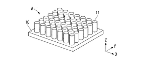
図1〜図6は、本発明の第1実施形態の固体二次電池の製造方法の説明図である。本実施形態では、まず、図1に示すように、基材10の表面に複数の柱状の突起11が形成された成形型Aを用意する。成形型Aは、例えば、板状の基材10上に板面と垂直な複数の円柱状の突起11を備えたものである。突起11は、X方向及びY方向にそれぞれ一定の間隔で周期的に配置されている。本実施形態の場合、突起11の高さは1200μmであり、突起11の直径は120μmであり、突起11の間隔(円柱の中心同士の間隔)は180μmである。
1-6 is explanatory drawing of the manufacturing method of the solid secondary battery of 1st Embodiment of this invention. In the present embodiment, first, as shown in FIG. 1, a mold A in which a plurality of
成形型Aは、例えばLIGA(Lithographie Galvanoformung Abformung)法を用いて形成される。LIGA法は、X線リソグラフィと電鋳およびモールディングを組み合わせ、アスペクト比の大きな微細な形状を作製する方法である。具体的には、厚さ100μm以上のレジストに直進性の良いシンクロトロン放射光装置から発生するX線を照射し、X線マスクを介してパターンを転写することにより、100μm以上の深さ(高さ)で横方向に任意の形状を持った超精密部品を製造するものである。シンクロトロン放射光の代わりに、紫外光でレジストパターンを形成するUV−LIGA法も知られており、LIGA法やUV−LIGA法で作製された形状を原型として複製型を作製し、電鋳物を形成する方法も知られている。 The mold A is formed using, for example, a LIGA (Lithographie Galvanoformung Abformung) method. The LIGA method is a method for producing a fine shape having a large aspect ratio by combining X-ray lithography, electroforming, and molding. Specifically, a resist having a thickness of 100 μm or more is irradiated with X-rays generated from a synchrotron radiation apparatus having good straightness, and a pattern is transferred through an X-ray mask to obtain a depth (higher than 100 μm). In this way, ultra-precision parts having an arbitrary shape in the lateral direction are manufactured. A UV-LIGA method for forming a resist pattern with ultraviolet light instead of synchrotron radiation is also known. A replica mold is produced using a shape produced by the LIGA method or UV-LIGA method as a prototype, and an electroformed product is produced. Methods of forming are also known.
LIGA法で成形型Aを作成する場合、例えば、金属基板上に厚さ1200μmのレジスト層(ポリメチルメタクリレート(PMMA))を形成し、シンクロトロン放射光(X線)を照射し、マスク上のX線吸収体のパターンをレジスト層に転写する。レジスト層のX線露光部分は、高分子の連鎖が切れて分子量が減少し現像液に溶解する。未露光部分は変化せずにそのまま残る。この結果、X線吸収体のパターンと同一形状のレジストの微細構造体が形成される。 When forming the mold A by the LIGA method, for example, a resist layer (polymethyl methacrylate (PMMA)) having a thickness of 1200 μm is formed on a metal substrate, irradiated with synchrotron radiation (X-rays), and then on the mask. The pattern of the X-ray absorber is transferred to the resist layer. In the X-ray exposed portion of the resist layer, the polymer chain is broken, the molecular weight is reduced, and the resist layer is dissolved in the developer. The unexposed part remains unchanged. As a result, a resist fine structure having the same shape as the pattern of the X-ray absorber is formed.
次に、めっきによって、レジスト層の溶解した部分に金属(例えば、ニッケル)を堆積させ金属構造体を作製する(電鋳)。そして、未露光部分のレジスト層を除去し、前記金属構造体からなる金型(モールド)を作製する。この金型は、成形型Aの突起11に対応した高アスペクト比の縦穴を有する板状体である。この金型に樹脂を鋳込み、成形型Aを作製する。
Next, metal (for example, nickel) is deposited on the dissolved portion of the resist layer by plating to produce a metal structure (electroforming). Then, the unexposed portion of the resist layer is removed to produce a mold (mold) made of the metal structure. This mold is a plate-like body having a high aspect ratio vertical hole corresponding to the
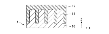
成形型Aを作製したら、図2に示すように、成形型Aの突起11が形成された面に正極活物質のゾルを塗布し、該ゾルを固化して成形型Aを除去する(ゾルゲル法)。これにより、正極活物質からなる板状の正極活物質層(第1活物質層)12が得られる。
After forming the mold A, as shown in FIG. 2, a positive electrode active material sol is applied to the surface of the mold A on which the
なお、成形型Aとして、ポリメチルメタクリレート(PMMA)等の樹脂を用いた場合、ゾルを固化するための高温の熱処理によって成形型Aは焼散するので、成形型Aを除去するための新たな工程は不要である。 When a resin such as polymethyl methacrylate (PMMA) is used as the mold A, the mold A is burned out by a high-temperature heat treatment for solidifying the sol, so that a new mold for removing the mold A can be obtained. No process is required.
正極活物質としては、コバルト酸リチウム(LiCoO2)、ニッケル酸リチウム(LiNiO2)、マンガン酸リチウム(LiMn2O4)、チタン酸リチウム(Li4Ti5O12)等を用いることができる。例えば、正極活物質としてコバルト酸リチウムを用いた場合には、ゾル原料として、水酸化リチウム(または酢酸リチウム)、酢酸コバルト、酢酸をイソプロピルアルコール(またはメタノール、エタノール)に溶解させた溶液を用いることができる。正極活物質としてニッケル酸リチウムを用いた場合には、ゾル原料として、水酸化リチウム(または酢酸リチウム)、酢酸ニッケル、酢酸をイソプロピルアルコール(またはメタノール、エタノール)に溶解させた溶液を用いることができる。正極活物質としてマンガン酸リチウムを用いた場合には、ゾル原料として、水酸化リチウム(または酢酸リチウム)、酢酸マンガン、酢酸、クエン酸をイソプロピルアルコール(またはメタノール、エタノール)に溶解させた溶液を用いることができる。正極活物質としてチタン酸リチウムを用いた場合には、ゾル原料として、水酸化リチウム(または酢酸リチウム)、チタン酸イソプロピル、酢酸をイソプロピルアルコール(またはメタノール、エタノール)に溶解させた溶液を用いることができる。 As the positive electrode active material, lithium cobaltate (LiCoO 2 ), lithium nickelate (LiNiO 2 ), lithium manganate (LiMn 2 O 4 ), lithium titanate (Li 4 Ti 5 O 12 ), or the like can be used. For example, when lithium cobaltate is used as the positive electrode active material, a solution in which lithium hydroxide (or lithium acetate), cobalt acetate, and acetic acid are dissolved in isopropyl alcohol (or methanol, ethanol) is used as the sol raw material. Can do. When lithium nickelate is used as the positive electrode active material, a solution in which lithium hydroxide (or lithium acetate), nickel acetate, and acetic acid are dissolved in isopropyl alcohol (or methanol, ethanol) can be used as the sol raw material. . When lithium manganate is used as the positive electrode active material, a solution in which lithium hydroxide (or lithium acetate), manganese acetate, acetic acid, and citric acid are dissolved in isopropyl alcohol (or methanol, ethanol) is used as the sol raw material. be able to. When lithium titanate is used as the positive electrode active material, a solution in which lithium hydroxide (or lithium acetate), isopropyl titanate, and acetic acid are dissolved in isopropyl alcohol (or methanol or ethanol) is used as the sol raw material. it can.
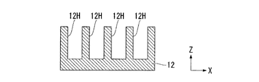
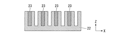
図3は、成形型Aを除去した後の正極活物質層12の断面図である。正極活物質層12は、表面に成形型Aの複数の突起11に対応した複数の縦穴12Hを有する。縦穴12Hは、X方向及びY方向に一定の間隔で周期的に配置されている。
FIG. 3 is a cross-sectional view of the positive electrode
正極活物質層12を作製したら、図4に示すように、正極活物質層12の縦穴12Hが形成された面に接して固体電解質を配置し、正極活物質層12の上面12a、縦穴12Hの底面12b及び内壁面12cを覆う薄膜状の固体電解質層13を形成する。
When the positive electrode
固体電解質層13の形成方法としては高アスペクト比の縦穴12Hの底面及び内壁面に均一な厚みの薄膜を形成できるものであれば、どのようなものでも良い。例えば、CVD法等の気相堆積法やゾルゲル法などを用いることができる。ゾルゲル法で形成する場合には固体電解質としてLi0.35La0.55TiO3を用いることができる。ゾル原料としては、水酸化リチウム(または酢酸リチウム)、酢酸ランタン、チタン酸イソプロピル、酢酸をイソプロピルアルコール(またはメタノール、エタノール)に溶解させた溶液を用いることができる。
The
固体電解質層13は、厚みが例えば100nm〜1μmの薄膜状に形成される。そのため、固体電解質層13によって縦穴12Hが埋没することはない。
The
固体電解質層13を形成したら、図5に示すように、固体電解質層13の正極活物質層12上で露出する部位をと接して負極活物質層(第2活物質層)14を形成する。負極活物質層14は、縦穴12Hの底面及び内壁面に形成された固体電解質層13を覆って、正極活物質層12の上面全体を覆うように形成される。負極活物質層14と正極活物質層12とは互いに接することなく、負極活物質層14と正極活物質層12との間に固体電解質層13を挟持する。
After the
負極活物質層14の形成方法としては、高アスペクト比の縦穴12Hの底面及び内壁面に負極活物質を配置できるものであれば、どのようなものでも良い。例えば、CVD法等の気相堆積法や、ゾルゲル法或いはインクジェット法等の液体プロセスを用いることができる。液体プロセスを用いた場合には、縦穴12Hの内部を埋めるように厚い負極活物質層を形成できるので、望ましい。
The negative electrode
液体プロセスで負極活物質層14を形成する場合には、負極活物質として、リチウムや、リチウムを固溶しかつ低融点の金属(インジウム、スズ、ウッドメタルなど)を用いることができる。これらの材料は融点が低いので、溶融して液体材料としてから固体電解質層13上に塗布することができる。
When the negative electrode
負極活物質としては、チタン酸リチウム(Li4Ti5O12)を用いることもできる。この場合、ゾルゲル法で形成することになるが、ゾル原料としては、水酸化リチウム(または酢酸リチウム)、チタン酸イソプロピル、酢酸をイソプロピルアルコール(またはメタノール、エタノール)に溶解させた溶液を用いることができる。この材料は標準電極電位が低いので、負極としても使えるというメリットがある。 As the negative electrode active material, lithium titanate (Li 4 Ti 5 O 12 ) can also be used. In this case, it is formed by a sol-gel method. As the sol raw material, a solution in which lithium hydroxide (or lithium acetate), isopropyl titanate, and acetic acid are dissolved in isopropyl alcohol (or methanol, ethanol) is used. it can. Since this material has a low standard electrode potential, it can be used as a negative electrode.
液体プロセスで負極活物質層14を形成した場合、負極活物質層14は縦穴12Hの内部を埋めるように形成される。そのため、負極活物質層14は、固体電解質を介して縦穴12Hの内部に埋め込まれた柱状の構造体を有するものとなる。
When the negative electrode
負極活物質層14を形成したら、図6に示すように、必要に応じて、正極活物質層12の裏面(縦穴12Hが形成された面とは反対側の面)に正極集電層15と正極配線層(図示略)を形成し、負極活物質層14の表面(固体電解質層13と接する面とは反対側の面)に負極集電層16と負極配線層(図示略)を形成する。これにより、固体二次電池1が完成する。
When the negative electrode
本実施形態の固体二次電池1によれば、縦穴12Hの底面12b及び内壁面12cに活物質と固体電解質の界面が形成されるため、特許文献2のように、単に平面上に正極薄膜、固体電解質薄膜、負極薄膜を積層していく場合に比べて、単位面積当たりの電池容量を飛躍的に向上させることができる。また、固体電解質は縦穴の底面及び内壁面に沿って薄膜状に形成されるため、活物質と固体電解質との界面接触が良好であり、且つ、固体電解質の厚さを小さくすることができるので、高い電池出力と良好なサイクル寿命特性が得られる。
According to the solid secondary battery 1 of the present embodiment, since the interface between the active material and the solid electrolyte is formed on the
なお、本実施形態の固体二次電池1では、縦穴12HのZ方向から見た平面形状を円形とし、縦穴12HをX方向とY方向に周期的に配置したが、縦穴12Hの平面形状はこれに限らず、種々の形状をとることができる。例えば、縦穴12Hの平面形状を正方形とし、隣接する縦穴同士の間隔を可能な範囲で短くすることで、縦穴の内壁面の面積を最大限広げることもできる。この場合、固体電解質と活物質との接触界面が大きくなるので、大容量の固体二次電池が提供できる。また、縦穴12Hの平面形状を正六角形とし、六角柱状の縦穴12Hが正極活物質層12の表面に最密充填されるようにしても良い。この場合も、同じような効果が得られる。
In the solid secondary battery 1 of the present embodiment, the planar shape of the
また、本実施形態の固体二次電池1では、正極活物質を活物質層12の材料として用いたが、負極活物質を活物質層12の材料として用いることもできる。この場合、負極活物質のゾルを成形型Aに塗布し、該ゾルを固化して負極活物質層を形成する。そして、負極活物質層に形成された縦穴の底面及び内壁面を覆って薄膜状の固体電解質層を形成し、固体電解質層の負極活物質層上で露出する部位を覆って正極活物質層を形成する。正極活物質層は、薄膜状に形成しても良いし、縦穴の内部を埋めるように、固体電解質層を介して縦穴の内部全体に充填されても良い。この構成によっても、固体電解質と活物質との接触界面を大きくすることができるので、大容量且つ高出力の固体二次電池がえられる。
Further, in the solid secondary battery 1 of the present embodiment, the positive electrode active material is used as the material of the
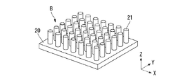
図7〜図12は、本発明の第2実施形態の固体二次電池の製造方法の説明図である。本実施形態では、まず、図7に示すように、基材20の表面に複数の柱状の突起21が形成された成形型Bを用意する。成形型Bは、例えば、板状の基材20上に板面と垂直な複数の円柱状の突起21を備えたものである。突起21は、X方向及びY方向にそれぞれ一定の間隔で周期的に配置されている。本実施形態の場合、突起21の高さは1200μmであり、突起21の直径は60μmであり、突起21の間隔(円柱の中心同士の間隔)は120μmである。成形型Bは、例えばLIGA法を用いて形成される。
7-12 is explanatory drawing of the manufacturing method of the solid secondary battery of 2nd Embodiment of this invention. In the present embodiment, first, as shown in FIG. 7, a forming die B in which a plurality of
そして、図8に示すように、成形型Bの突起21が形成された面に固体電解質のゾルを塗布し、該ゾルを固化して成形型Bを除去する(ゾルゲル法)。これにより、固体電解質からなる板状の固体電解質層22が得られる。固体電解質としては、前述したLi0.35La0.55TiO3等を用いることができる。
Then, as shown in FIG. 8, a solid electrolyte sol is applied to the surface of the mold B on which the
なお、成形型Bとして、ポリメチルメタクリレート(PMMA)等の樹脂を用いた場合、ゾルを固化するための高温の熱処理によって成形型Bは焼散するので、成形型Bを除去するための新たな工程は不要である。 When a resin such as polymethyl methacrylate (PMMA) is used as the mold B, the mold B is burned out by a high-temperature heat treatment for solidifying the sol, so that a new mold for removing the mold B can be obtained. No process is required.
図9は、成形型Bを除去した後の固体電解質層22の断面図である。固体電解質層22は、表面に成形型Bの複数の突起21に対応して形成された複数の縦穴22Hを有する。縦穴22Hは、X方向及びY方向に一定の間隔で周期的に配置されている。
FIG. 9 is a cross-sectional view of the
固体電解質層22を作製したら、図10に示すように、複数の縦穴22Hのうちの一部の縦穴に正極活物質を配置し、該縦穴22Hの底面及び内壁面に接して正極活物質層(第1活物質層)23を形成する。また、図11に示すように、負極活物質層23が形成された縦穴以外の縦穴22Hに負極活物質を配置し、該縦穴22Hの底面及び内壁面に接して負極活物質層(第2活物質層)24を形成する。
When the
活物質層23,24の形成方法としては、高アスペクト比の縦穴22Hの底面及び内壁面に活物質を配置できるものであれば、どのようなものでも良い。例えば、CVD法等の気相堆積法や、ゾルゲル法或いはインクジェット法等の液体プロセスを用いることができる。液体プロセスを用いた場合には、縦穴22Hの内部を埋めるように厚い活物質層を形成できるので、望ましい。特にインクジェット法を用いた場合には、吐出する液体材料の位置や量を精密に制御することができるため、正極活物質と負極活物質の塗りわけを確実に行うことができる。
The active material layers 23 and 24 may be formed by any method as long as the active material can be disposed on the bottom surface and the inner wall surface of the high aspect ratio
ゾルゲル法で活物質層23を形成する場合には、正極活物質及び負極活物質として、前述のものを用いることができる。すなわち、正極活物質としては、コバルト酸リチウム(LiCoO2)、ニッケル酸リチウム(LiNiO2)、マンガン酸リチウム(LiMn2O4)、チタン酸リチウム(Li4Ti5O12)等を用いることができ、負極活物質としては、チタン酸リチウム(Li4Ti5O12)等を用いることができる。
When the
正極活物質層23と負極活物質層24は、どちらを先に形成してもよく、両方同時に形成することもできる。正極活物質層23と負極活物質層34は、X方向とY方向の双方において交互に且つ周期的に配置される。
Either the positive electrode
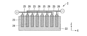
正極活物質層23と負極活物質層24を形成したら、図12に示すように、必要に応じて、正極活物層23の縦穴22Hから露出する部分に正極集電層25と正極配線層(図示略)を形成し、負極活物質層14の縦穴22Hから露出する部分に負極集電層26と負極配線層(図示略)を形成する。これにより、固体二次電池2が完成する。
When the positive electrode
本実施形態の固体二次電池2によれば、縦穴22Hの底面及び内壁面に活物質と固体電解質の界面が形成されるため、特許文献2のように、単に平面上に正極薄膜、固体電解質薄膜、負極薄膜を積層していく場合に比べて、単位面積当たりの電池容量を飛躍的に向上させることができる。また、電池として機能する部分の固体電解質の厚みは、隣接する活物質層間の距離によって決まるため、この距離を短くすることで、高い電池出力と良好なサイクル寿命特性が得られる。
According to the solid
なお、本実施形態の固体二次電池2では、縦穴22HのZ方向から見た平面形状を円形とし、縦穴22HをX方向とY方向に周期的に配置したが、縦穴22Hの平面形状はこれに限らず、種々の形状をとることができる。例えば、縦穴22Hの平面形状を正方形とし、隣接する縦穴同士の間隔を可能な範囲で短くすることで、縦穴の内壁面の面積を最大限広げることもできる。この場合、固体電解質と活物質との接触界面が大きくなるので、大容量の固体二次電池が提供できる。また、縦穴22Hの平面形状を正六角形とし、六角柱状の縦穴22Hが固体電解質層22の表面に最密充填されるようにしても良い。この場合も、同じような効果が得られる。
In the solid
1,2…固体二次電池、11…突起、12…正極活物質層(第1活物質層)、12H…縦穴、13…固体電解質層、14…負極活物質層(第2活物質層)、21…突起、22…固体電解質層、22H…縦穴、23…正極活物質層(第1活物質層)、24…負極活物質層(第2活物質層)、A,B…成形型
DESCRIPTION OF
Claims (10)
複数の穴を有する第1活物質層を形成する第1の工程と、
前記複数の穴の表面及び前記第1活物質層の表面に固体電解質層を形成する第2の工程と、
前記固体電解質層の表面に第2活物質層を形成する第3の工程と、
を備え、
前記第1の工程は、
表面に複数の突起が形成された成形型に、前記第1活物質層を形成するための第1の液体材料を塗布する第1の副工程と、
前記第1の液体材料を固化し、前記第1活物質層とする第2の副工程と、
前記第1活物質層と前記成形型とを分離する第3の副工程と、
を含み、
前記第1活物質層及び前記第2活物質層のうち一方は正極側の活物質として機能し、前記第1活物質層及び前記第2活物質層のうち他方は負極側の活物質として機能し、
前記複数の穴は複数の縦穴であり、
前記固体電解質層は前記複数の縦穴の底面及び内壁面に接して形成され、
前記第2活物質層は、前記固体電解質層を介して、前記複数の穴の各々の内部を埋めるように充填され、
前記第1活物質層と平行な面内における互いに直交する2方向をX方向およびY方向とし、前記X方向および前記Y方向と直交する方向をZ方向としたときに、前記複数の穴は前記X方向と前記Y方向にそれぞれ一定の間隔で周期的に配置され、前記Z方向から見た前記複数の穴の各々の平面形状は円形であり、前記複数の穴の直径は互いに等しく、前記複数の穴の配置間隔は、前記穴の直径の1.5〜2倍であることを特徴とする固体二次電池の製造方法。 A method for manufacturing a solid secondary battery, comprising:
A first step of forming a first active material layer having a plurality of holes;
A second step of forming a solid electrolyte layer on the surface of the plurality of holes and the surface of the first active material layer;
A third step of forming a second active material layer on the surface of the solid electrolyte layer;
With
The first step includes
A first sub-step of applying a first liquid material for forming the first active material layer to a mold having a plurality of protrusions formed on the surface;
A second sub-step of solidifying the first liquid material to form the first active material layer;
A third sub-process for separating the first active material layer and the mold;
Including
One of the first active material layer and the second active material layer functions as an active material on the positive electrode side, and the other of the first active material layer and the second active material layer functions as an active material on the negative electrode side. And
The plurality of holes are a plurality of vertical holes;
The solid electrolyte layer is formed in contact with the bottom and inner wall surfaces of the plurality of vertical holes,
The second active material layer is filled through the solid electrolyte layer so as to fill each of the plurality of holes,
When two directions orthogonal to each other in a plane parallel to the first active material layer are defined as an X direction and a Y direction, and a direction orthogonal to the X direction and the Y direction is defined as a Z direction, the plurality of holes are The plurality of holes are periodically arranged in the X direction and the Y direction at regular intervals, the planar shape of each of the plurality of holes viewed from the Z direction is circular, and the diameters of the plurality of holes are equal to each other. The method of manufacturing a solid secondary battery according to claim 1, wherein an interval between the holes is 1.5 to 2 times a diameter of the holes.
前記成形型を樹脂で形成し、前記熱処理で前記成形型を焼散させることで、前記第2の副工程と前記第3の副工程とを1つの工程として行うことを特徴とする請求項1または2に記載の固体二次電池の製造方法。 A step of performing a heat treatment in the second sub-step;
Said mold is formed of resin, the mold that causes Shochi in the heat treatment, claim 1, characterized in that the second sub-step and said third sub-step as one step or a method for manufacturing a solid-state secondary battery according to 2.
複数の第1の穴及び複数の第2の穴が形成された固体電解質層を形成する第1の工程と、
前記複数の第1の穴の内部に第1活物質層を形成する第2の工程と、
前記複数の第2の穴の内部に第2活物質層を形成する第3の工程と、
を備え、
前記第1の工程は、
表面に複数の突起が形成された成形型に前記固体電解質層の第1の液体材料を塗布する第1の副工程と、
前記第1の液体材料を固化し、前記固体電解質層とする第2の副工程と、
前記固体電解質層と前記成形型とを分離する第3の副工程と、
を含み、
前記複数の第1の穴のいずれかと前記複数の第2の穴のいずれかとは前記固体電解質層を介して配置され、
前記第1活物質層及び前記第2活物質層のうちの一方は正極側の活物質として機能し、前記第1活物質層及び前記第2活物質層のうちの他方は負極側の活物質として機能し、
前記複数の第1の穴の各々は縦穴であり、前記複数の第2の穴の各々は縦穴であり、
前記第2の工程は、前記複数の第1の穴の表面に接するように前記第1活物質層を形成し、
前記第3の工程は、前記複数の第2の穴の表面に接するように前記第2活物質層を形成し、
前記複数の第1の穴のいずれかと前記複数の第2の穴のいずれかとが前記固体電解質層を介して隣りあうように配置され、
前記第1活物質層は、前記複数の第1の穴の各々の内部全体に充填され、
前記第2活物質層は、前記複数の第2の穴の各々の内部全体に充填され、
前記複数の第1の穴の各々と前記複数の第2の穴の各々とが交互に、かつ、周期的に配置され、
前記固体電解質層と平行な面内における互いに直交する2方向をX方向およびY方向とし、前記X方向および前記Y方向と直交する方向をZ方向としたときに、前記複数の第1の穴および前記複数の第2の穴を含む複数の穴は前記X方向と前記Y方向にそれぞれ一定の間隔で周期的に配置され、前記Z方向から見た前記複数の穴の各々の平面形状は円形であり、前記複数の穴の直径は互いに等しく、前記複数の穴の配置間隔は、前記穴の直径の1.5〜2倍であることを特徴とする固体二次電池の製造方法。 A method for manufacturing a solid secondary battery, comprising:
A first step of forming a solid electrolyte layer in which a plurality of first holes and a plurality of second holes are formed;
A second step of forming a first active material layer inside the plurality of first holes;
A third step of forming a second active material layer inside the plurality of second holes;
With
The first step includes
A first sub-step of applying a first liquid material of the solid electrolyte layer to a mold having a plurality of protrusions formed on the surface;
A second sub-step of solidifying the first liquid material into the solid electrolyte layer;
A third sub-process for separating the solid electrolyte layer and the mold;
Including
One of the plurality of first holes and one of the plurality of second holes are arranged via the solid electrolyte layer,
One of the first active material layer and the second active material layer functions as an active material on the positive electrode side, and the other of the first active material layer and the second active material layer is an active material on the negative electrode side. Function as
Each of the plurality of first holes is a vertical hole, and each of the plurality of second holes is a vertical hole,
In the second step, the first active material layer is formed in contact with the surfaces of the plurality of first holes,
In the third step, the second active material layer is formed in contact with the surfaces of the plurality of second holes,
Any one of the plurality of first holes and any one of the plurality of second holes are arranged so as to be adjacent to each other via the solid electrolyte layer,
The first active material layer is filled in the entire interior of each of the plurality of first holes,
The second active material layer is filled in the entire interior of each of the plurality of second holes,
Each of the plurality of first holes and each of the plurality of second holes are alternately and periodically disposed,
When the two directions perpendicular to each other in a plane parallel to the solid electrolyte layer are defined as an X direction and a Y direction, and the direction perpendicular to the X direction and the Y direction is defined as a Z direction, the plurality of first holes and The plurality of holes including the plurality of second holes are periodically arranged at regular intervals in the X direction and the Y direction, and the planar shape of each of the plurality of holes viewed from the Z direction is circular. The method of manufacturing a solid secondary battery, wherein the diameters of the plurality of holes are equal to each other, and the arrangement interval of the plurality of holes is 1.5 to 2 times the diameter of the holes.
前記成形型を樹脂で形成し、前記熱処理で前記成形型を焼散させることで、前記第2の副工程と前記第3の副工程を1つの工程として行うことを特徴とする請求項6または7に記載の固体二次電池の製造方法。 A step of performing a heat treatment in the second sub-step;
Said mold is formed of resin, the mold that causes Shochi in the heat treatment according to claim 6, characterized in that the second sub-step and the third sub-step as one step or A method for producing the solid secondary battery according to claim 7 .
前記第3の工程は、前記第2活物質層を形成する液体材料を前記第2の穴の内部に充填する第5の副工程を含むことを特徴とする請求項6乃至8のいずれかに記載の固体二次電池の製造方法。 The second step includes a fourth sub-step of filling the first hole with a liquid material that forms the first active material layer,
The third step, in any one of claims 6 to 8, characterized in that it comprises a fifth sub-step of filling a liquid material for forming the second active material layer inside the second hole The manufacturing method of the solid secondary battery as described.
Priority Applications (1)
| Application Number | Priority Date | Filing Date | Title |
|---|---|---|---|
| JP2009071814A JP5572974B2 (en) | 2009-03-24 | 2009-03-24 | Manufacturing method of solid secondary battery |
Applications Claiming Priority (1)
| Application Number | Priority Date | Filing Date | Title |
|---|---|---|---|
| JP2009071814A JP5572974B2 (en) | 2009-03-24 | 2009-03-24 | Manufacturing method of solid secondary battery |
Related Child Applications (1)
| Application Number | Title | Priority Date | Filing Date |
|---|---|---|---|
| JP2014098105A Division JP5817885B2 (en) | 2014-05-09 | 2014-05-09 | Solid secondary battery |
Publications (3)
| Publication Number | Publication Date |
|---|---|
| JP2010225432A JP2010225432A (en) | 2010-10-07 |
| JP2010225432A5 JP2010225432A5 (en) | 2012-04-12 |
| JP5572974B2 true JP5572974B2 (en) | 2014-08-20 |
Family
ID=43042408
Family Applications (1)
| Application Number | Title | Priority Date | Filing Date |
|---|---|---|---|
| JP2009071814A Expired - Fee Related JP5572974B2 (en) | 2009-03-24 | 2009-03-24 | Manufacturing method of solid secondary battery |
Country Status (1)
| Country | Link |
|---|---|
| JP (1) | JP5572974B2 (en) |
Cited By (2)
| Publication number | Priority date | Publication date | Assignee | Title |
|---|---|---|---|---|
| WO2018038479A1 (en) * | 2016-08-25 | 2018-03-01 | 주식회사 엘지화학 | Electrode for secondary battery comprising fine holes |
| US10818929B2 (en) | 2016-08-25 | 2020-10-27 | Lg Chem, Ltd. | Electrode for secondary battery having fine holes |
Families Citing this family (15)
| Publication number | Priority date | Publication date | Assignee | Title |
|---|---|---|---|---|
| JP5734790B2 (en) * | 2011-08-23 | 2015-06-17 | 株式会社Screenホールディングス | Method for manufacturing battery electrode |
| US10515768B2 (en) * | 2012-04-04 | 2019-12-24 | Lyten, Inc. | Apparatus and associated methods |
| US9324995B2 (en) | 2012-04-04 | 2016-04-26 | Nokia Technologies Oy | Apparatus and associated methods |
| US9362565B2 (en) | 2012-04-04 | 2016-06-07 | Nokia Technologies Oy | Apparatus and associated methods |
| JP5918019B2 (en) | 2012-05-18 | 2016-05-18 | 株式会社オハラ | All solid state secondary battery |
| KR102081102B1 (en) * | 2012-05-24 | 2020-02-25 | 엘지디스플레이 주식회사 | Touch panel integrated display having thin film battery and method for fabricating of thin film battery |
| JP5678928B2 (en) * | 2012-07-31 | 2015-03-04 | トヨタ自動車株式会社 | All-solid battery and method for manufacturing the same |
| JP2014175155A (en) * | 2013-03-08 | 2014-09-22 | Toppan Printing Co Ltd | Electrode for nonaqueous electrolyte secondary battery, method for manufacturing the same, and nonaqueous electrolyte secondary battery |
| JP6432722B2 (en) * | 2013-07-30 | 2018-12-05 | 俊 保坂 | Semiconductor sensor device and manufacturing method thereof |
| JP6536515B2 (en) * | 2016-08-15 | 2019-07-03 | トヨタ自動車株式会社 | Lithium ion battery and method of manufacturing lithium ion battery |
| JP6738706B2 (en) * | 2016-09-29 | 2020-08-12 | 三洋化成工業株式会社 | Lithium ion battery |
| WO2018144808A1 (en) * | 2017-02-02 | 2018-08-09 | Weimin Li | High power lithium ion battery and the method to form |
| KR102939239B1 (en) * | 2020-12-23 | 2026-03-13 | 주식회사 엘지에너지솔루션 | ELECTRODE ASSEMBLY, SECONDARY BATTERY AND MANUFACTURING METHOD of ELECTRODE ASSEMBLY |
| CN114267876B (en) * | 2021-12-20 | 2024-07-16 | 上海科技大学 | An integrated electrode-electrolyte structure and preparation method thereof and all-solid-state battery |
| JP7827490B2 (en) * | 2022-03-03 | 2026-03-10 | セイコーインスツル株式会社 | Method for manufacturing an electrochemical cell |
Family Cites Families (9)
| Publication number | Priority date | Publication date | Assignee | Title |
|---|---|---|---|---|
| JPH05109429A (en) * | 1991-10-14 | 1993-04-30 | Ricoh Co Ltd | Laminated body having electron conductor layer and ion conductor layer and its manufacture |
| US7553584B2 (en) * | 2000-10-20 | 2009-06-30 | Massachusetts Institute Of Technology | Reticulated and controlled porosity battery structures |
| JP4920169B2 (en) * | 2003-10-06 | 2012-04-18 | 日産自動車株式会社 | Battery and vehicle equipped with this battery |
| KR101161197B1 (en) * | 2004-06-08 | 2012-06-29 | 도꾸리쯔교세이호징 리가가쿠 겐큐소 | Method of forming a nano-structure and the nano-structure |
| CN101069310A (en) * | 2004-11-26 | 2007-11-07 | 皇家飞利浦电子股份有限公司 | Electrochemical energy source, electronic module, electronic device and method for producing said energy source |
| FR2880197B1 (en) * | 2004-12-23 | 2007-02-02 | Commissariat Energie Atomique | ELECTROLYTE STRUCTURE FOR MICROBATTERY |
| JP5181413B2 (en) * | 2005-09-13 | 2013-04-10 | 日立電線株式会社 | Electrode for electrochemical device, solid electrolyte / electrode assembly and method for producing the same |
| JP2007273249A (en) * | 2006-03-31 | 2007-10-18 | Arisawa Mfg Co Ltd | Method for producing lithium ion secondary battery |
| JP2008078119A (en) * | 2006-08-25 | 2008-04-03 | Ngk Insulators Ltd | Totally solid storage element |
-
2009
- 2009-03-24 JP JP2009071814A patent/JP5572974B2/en not_active Expired - Fee Related
Cited By (2)
| Publication number | Priority date | Publication date | Assignee | Title |
|---|---|---|---|---|
| WO2018038479A1 (en) * | 2016-08-25 | 2018-03-01 | 주식회사 엘지화학 | Electrode for secondary battery comprising fine holes |
| US10818929B2 (en) | 2016-08-25 | 2020-10-27 | Lg Chem, Ltd. | Electrode for secondary battery having fine holes |
Also Published As
| Publication number | Publication date |
|---|---|
| JP2010225432A (en) | 2010-10-07 |
Similar Documents
| Publication | Publication Date | Title |
|---|---|---|
| JP5572974B2 (en) | Manufacturing method of solid secondary battery | |
| US12183892B2 (en) | Electrode assembly manufacture and device | |
| US8865345B1 (en) | Electrodes for three-dimensional lithium batteries and methods of manufacturing thereof | |
| JP6644373B2 (en) | Stair structure battery cell | |
| CN101584065B (en) | Three-dimensional batteries and methods of manufacturing the same | |
| Katsuyama et al. | A 3D‐Printed, Freestanding Carbon Lattice for Sodium Ion Batteries | |
| TWI745651B (en) | Separators for three-dimensional batteries | |
| KR102204304B1 (en) | Li metal secondary battery and method for fabricating the same | |
| US10381651B2 (en) | Device and method of manufacturing high-aspect ratio structures | |
| CN101517815B (en) | Method for manufacturing lithium rechargeable battery, and lithium rechargeable battery | |
| KR20080058772A (en) | Manufacturing Method of Battery Electrode | |
| JP2010135332A5 (en) | ||
| JP2015519691A (en) | Non-standard battery pack | |
| KR20140085323A (en) | Three dimensional co-extruded battery electrodes | |
| JP2009266589A (en) | Solid lithium secondary battery and method of manufacturing the same | |
| JP5787307B2 (en) | Porous electrode for secondary battery | |
| Cardenas et al. | 3D printing of ridged FeS2 cathodes for improved rate capability and custom-form lithium batteries | |
| JP6559804B2 (en) | Gas trap removal device for battery cell manufacturing using vibration | |
| JP6368044B2 (en) | Wound electrode body for galvanic element and method of manufacturing the same | |
| JP5817885B2 (en) | Solid secondary battery | |
| JP6282263B2 (en) | Nonaqueous electrolyte secondary battery | |
| TWI398031B (en) | Lithium ion battery assembly | |
| Yang et al. | Photolithographic structuring of ordered silicon micropillar electrodes for lithium-ion batteries and electrochemical performance | |
| KR101514875B1 (en) | Secondary battery | |
| JP5250365B2 (en) | Electrode plate for lithium ion secondary battery and lithium ion secondary battery |
Legal Events
| Date | Code | Title | Description |
|---|---|---|---|
| RD04 | Notification of resignation of power of attorney |
Free format text: JAPANESE INTERMEDIATE CODE: A7424 Effective date: 20120130 |
|
| A521 | Request for written amendment filed |
Free format text: JAPANESE INTERMEDIATE CODE: A523 Effective date: 20120228 |
|
| A621 | Written request for application examination |
Free format text: JAPANESE INTERMEDIATE CODE: A621 Effective date: 20120228 |
|
| A131 | Notification of reasons for refusal |
Free format text: JAPANESE INTERMEDIATE CODE: A131 Effective date: 20130423 |
|
| A977 | Report on retrieval |
Free format text: JAPANESE INTERMEDIATE CODE: A971007 Effective date: 20130424 |
|
| A131 | Notification of reasons for refusal |
Free format text: JAPANESE INTERMEDIATE CODE: A131 Effective date: 20140311 |
|
| A521 | Request for written amendment filed |
Free format text: JAPANESE INTERMEDIATE CODE: A523 Effective date: 20140509 |
|
| TRDD | Decision of grant or rejection written | ||
| A01 | Written decision to grant a patent or to grant a registration (utility model) |
Free format text: JAPANESE INTERMEDIATE CODE: A01 Effective date: 20140603 |
|
| A61 | First payment of annual fees (during grant procedure) |
Free format text: JAPANESE INTERMEDIATE CODE: A61 Effective date: 20140616 |
|
| R150 | Certificate of patent or registration of utility model |
Ref document number: 5572974 Country of ref document: JP Free format text: JAPANESE INTERMEDIATE CODE: R150 |
|
| S531 | Written request for registration of change of domicile |
Free format text: JAPANESE INTERMEDIATE CODE: R313531 |
|
| R350 | Written notification of registration of transfer |
Free format text: JAPANESE INTERMEDIATE CODE: R350 |
|
| LAPS | Cancellation because of no payment of annual fees |