JP5567936B2 - Training equipment - Google Patents
Training equipment Download PDFInfo
- Publication number
- JP5567936B2 JP5567936B2 JP2010186987A JP2010186987A JP5567936B2 JP 5567936 B2 JP5567936 B2 JP 5567936B2 JP 2010186987 A JP2010186987 A JP 2010186987A JP 2010186987 A JP2010186987 A JP 2010186987A JP 5567936 B2 JP5567936 B2 JP 5567936B2
- Authority
- JP
- Japan
- Prior art keywords
- weight
- fulcrum
- rotation
- load
- support member
- Prior art date
- Legal status (The legal status is an assumption and is not a legal conclusion. Google has not performed a legal analysis and makes no representation as to the accuracy of the status listed.)
- Active
Links
Images


Description
本発明は、使用者が負荷に抗して操作部を移動操作することにより、身体の筋肉または関節を動かすトレーニング装置に関する。 The present invention relates to a training apparatus that moves a muscle or a joint of a body by a user moving and operating an operation unit against a load.
ウェイト等の負荷に抗して可動部を移動操作することにより、身体の筋肉または関節を発達または強化するためのトレーニング装置が知られている。この種のトレーニング装置として、可動部を移動操作する間に亘ってウェイト等の負荷が作用し続けるものが一般的である。この種の負荷は、筋肉の緊張状態を維持して筋肉を強化するトレーニングに好適である。 2. Description of the Related Art Training apparatuses for developing or strengthening body muscles or joints by moving a movable part against a load such as a weight are known. As this type of training device, a device in which a load such as a weight continues to act during a moving operation of the movable part is generally used. This type of load is suitable for training to maintain muscle tension and strengthen muscles.
これに対して、初動時から負荷が漸減または減少することにより、筋肉の緊張状態の他に筋肉の弛緩状態を可能とするトレーニング装置も提案されている。このような負荷の与え方は、肥大化した筋肉の発達を目的とするのではなく、むしろ柔軟な筋肉の発達に寄与すること等を目的としている。 On the other hand, a training apparatus that enables a relaxed state of muscles in addition to a strained state of muscles by gradually decreasing or decreasing the load from the initial movement has been proposed. The method of giving such a load is not intended to develop enlarged muscles, but rather to contribute to the development of flexible muscles.
特許文献1〜7は、負荷を漸減または減少させ、あるいは負荷を解除できるトレーニング装置を提案している。また、特許文献8〜10は、トレーニング装置において、使用者によって操作される操作部の間隔を調節する技術を開示している。
特許文献1は、一定重量のウェイトに連結されたチェーンやワイヤー等が巻回されて連結されるプーリーと、そのプーリーと同軸で回転する特殊な輪郭を有するカムと、一端がカムに連結されて巻きつけられるチェーンやワイヤー等の他端が連結されるフットペダルとを有する、レッグプレス装置を提案している。フットペダルの位置に応じて、カムのモーメントアームの長さが変化して、初動時から連続性をもって負荷が漸減または漸増される。例えば、特許文献1の図2に示すように脚を伸張した初期に最大負荷(約244kg)であったのが、特許文献1の図3に示す中間屈伸状態では最小負荷(約91kg)まで漸減する。その後、特許文献1の図4に示すように、最大屈伸時には負荷が約183kgまで漸増する。
特許文献2〜4でも、特許文献1と同様な原理を用いたアームカール、アームエクステンションまたはレッグプレスのためのトレーニング装置を提案している。特許文献2〜4では、一定重量のウェイトに連結されたチェーンやワイヤー等が巻回される少なくとも1個の滑車を変形カムとして、変形カムのモーメントアームの長さが変化して、初動時から連続性をもって負荷が漸減または漸増される。
Patent Documents 2 to 4 also propose a training device for arm curl, arm extension, or leg press using the same principle as
特許文献1〜4は、作用させる負荷の大きさに従ってモーメントアームの長さが変化するように、カムの輪郭を加工形成しなくてはならない。このような特殊形状のカムは、加工が困難なことに加えて、その加工費用がトレーニング装置のコストに上乗せされてしまう。
In
特許文献5では、回転操作アームに連結されたハブと摩擦板との間に一方向クラッチを設け、ハブと摩擦板との間に生ずる摩擦力を回転操作アームに伝達し、または伝達解除する動作を、一方向クラッチを介して行っている。こうして、回転操作アームに対して、負荷を作用させ、あるいは負荷を作用させなくできる。しかし、負荷を漸減または漸増することができず、摩擦力だけでは大きな負荷は期待できない。 In Patent Document 5, a one-way clutch is provided between a hub and a friction plate connected to a rotation operation arm, and a friction force generated between the hub and the friction plate is transmitted to or released from the rotation operation arm. Through a one-way clutch. In this way, a load can be applied to the rotary operation arm or no load can be applied. However, the load cannot be gradually decreased or increased, and a large load cannot be expected only by the frictional force.
特許文献6では、弛緩動作を可能とするために、ウェイトに連結されたチェーンの長さに余裕をもたせ、あるいは負荷方向と弛緩方向とをギアやスイッチで切り替えると記載されている。しかし、それらの構造について図面での開示がなく、その構造の詳細は不明である。 Patent Document 6 describes that in order to enable a relaxing operation, there is a margin in the length of the chain connected to the weight, or the load direction and the relaxation direction are switched by a gear or a switch. However, these structures are not disclosed in the drawings, and the details of the structures are unknown.
特許文献7は、シーソーのように揺動するアームの中間支点よりも一端に操作部を設け、中間支点と操作部との間、あるいは中間支点よりも他端側にウェイトを配置している。この構成では、支点と荷重作用線との距離を変化させて負荷を増減できる。しかし、操作部と一体のアームにウェイトが支持されているので、重量の大きいウェイトを配置することは危険であり、負荷の大きさに制約が生ずる。
In
このように、従来、初動時から連続性をもって負荷の大きさを変化させるには、一定重量のウェイトと操作部とを連結するチェーンやワイヤー等が巻回されプーリーや滑車を変形カムとするしか、有効な手法が提案されていなかった。 As described above, conventionally, in order to change the magnitude of the load with continuity from the initial operation, a chain or a wire connecting a weight of a constant weight and an operation unit is wound and a pulley or pulley is used as a deformation cam. No effective method has been proposed.
また、特許文献8は、アームカールまたはアームエクステンションのためのトレーニング装置において、両手で把持される2つのグリップを操作アームに沿ってスライド可能として、2つのグリップの間隔を調整可能としている。しかし、2つのグリップの間隔は調整できても、2つのグリップの各々が独立してスライド移動するので、2つのグリップの中心位置がトレーニング装置の中心位置からずれてしまう欠点がある。この問題は、2つのグリップを支持するアームをスライド可能とした機構を有する特許文献9でも同様に生ずる。しかも、特許文献8,9では、2つのアームのスライド移動量と同じ量だけしたグリップ間隔が調整できなかった。 Japanese Patent Laid-Open No. 2004-228561 makes it possible to slide two grips gripped with both hands along the operation arm in a training device for arm curl or arm extension, and to adjust the interval between the two grips. However, even if the interval between the two grips can be adjusted, each of the two grips slides independently, so that the center position of the two grips is deviated from the center position of the training apparatus. This problem also occurs in Patent Document 9 having a mechanism that enables sliding of an arm that supports two grips. Moreover, in Patent Documents 8 and 9, the grip interval that is the same amount as the sliding movement amount of the two arms cannot be adjusted.
特許文献10は、負荷に抗して両腕によって開閉される2つのアームパッドの間隔を、無負荷状態の初期に調整できるトレーニング装置を提案している。使用者によって操作される2つのアームパッドの回転軸には、互いに噛み合う2つのセクタギアが固定され、2つのアームパッドは対称的に移動できるようになっている。 Patent Document 10 proposes a training device that can adjust the interval between two arm pads that are opened and closed by both arms against a load in the initial state of no load. Two sector gears that mesh with each other are fixed to the rotation shafts of the two arm pads operated by the user, and the two arm pads can be moved symmetrically.
このようなトレーニング装置において、2つのアームパッドの間隔を調整するために、2つのアームパッドの各々は、その回転軸に固定された水平アームに対して揺動可能に支持され、所定揺動角度を脱着ピンによって選択できるように構成されている(特許文献10の図4及び段落0013)。よって、2つのアームパッドの間隔を調整するには、2つのアームパッドが水平アームに対する揺動角度を個々に調整しなければならない。つまり、特許文献10においても特許文献8,9と同様に、2つのグリップの間隔は調整できても、2つのグリップの各々が独立して移動するので、2つのグリップの中心位置がトレーニング装置の中心位置からずれてしまう欠点がある。 In such a training apparatus, in order to adjust the interval between the two arm pads, each of the two arm pads is supported so as to be swingable with respect to a horizontal arm fixed to the rotation shaft, and has a predetermined swing angle. Can be selected by a desorption pin (FIG. 4 of Patent Document 10 and paragraph 0013). Therefore, in order to adjust the interval between the two arm pads, the swing angles of the two arm pads with respect to the horizontal arm must be individually adjusted. That is, in Patent Document 10 as well as Patent Documents 8 and 9, even though the distance between the two grips can be adjusted, each of the two grips moves independently. There is a drawback that the center position shifts.
さらに、この種のトレーニング装置は、ウェイトを用いて操作部に負荷を作用させているが、例えば特許文献6の図1〜図4に示すように、ウェイトはトレーニング装置の側面または背面にはみ出して設けられていた。この種のトレーニング装置は、今後は病院、リハビリテーション施設、さらには家庭へと普及する傾向にあり、装置の小型化が切望されていた。 Furthermore, this type of training device uses a weight to apply a load to the operation unit. For example, as shown in FIGS. 1 to 4 of Patent Document 6, the weight protrudes from the side or back of the training device. It was provided. This type of training device tends to spread to hospitals, rehabilitation facilities, and even homes in the future, and downsizing of the device has been desired.
そこで、本発明の幾つかの態様では、変形カムを用いることなく負荷の大きさを変化させることができる新規で簡易な構造のトレーニング装置を提供することを目的とする。 Accordingly, some aspects of the present invention have an object to provide a training device having a new and simple structure capable of changing the magnitude of a load without using a deformation cam.
本発明の他の幾つかの態様は、使用者により操作される2つの操作部を同期して移動させて、2つの操作部の間隔を調整する新規で簡易な構造のトレーニング装置を提供することを目的とする。 Some other aspects of the present invention provide a training device having a new and simple structure in which two operation units operated by a user are moved in synchronization to adjust an interval between the two operation units. With the goal.
本発明のさらに他の幾つかの態様は、ウェイトを用いて負荷を作用させながら、ウェイトをデッドスペースに配置してコンパクト化することができるトレーニング装置を提供することを目的とする。 Still another aspect of the present invention is to provide a training apparatus that can be made compact by placing weights in a dead space while applying a load using the weights.
本発明の一態様は、使用者が負荷に抗して操作部を移動操作することにより、身体の筋肉または関節を動かすトレーニング装置において、
前記操作部を往復移動可能に支持する支持部材と、
回動支点に回動可能に支持され、正逆方向の回動により、前記回動支点の周りのモーメントを可変する少なくとも一つウェイトと、
前記支持部材と前記ウェイトとを連結して、前記操作部の往復移動に連動させて前記ウェイトを前記正逆方向に回動させる連結部材と、
を有することを特徴とする。
One aspect of the present invention is a training apparatus that moves a muscle or a joint of a body by a user moving and operating an operation unit against a load.
A support member that supports the operation unit in a reciprocating manner;
At least one weight that is rotatably supported by the pivoting fulcrum and varies the moment around the pivoting fulcrum by forward and reverse rotation;
A connecting member that connects the support member and the weight and rotates the weight in the forward / reverse direction in conjunction with the reciprocating movement of the operation unit;
It is characterized by having.
本発明の一態様では、使用者が操作部を操作すると、支持部材及び連結部材を介して、ウェイトが回動支点の廻りで回動される。このウェイトの変位は、回動支点の廻りのモーメントを可変させるので、使用者が操作部を移動操作する時に抗すべき負荷の大きさが可変される。従って、本発明の一態様では特殊な変形カムを用いることなく、操作部の往復移動操作中に負荷の大きさを変化させることができるトレーニング装置を提供できる。 In one aspect of the present invention, when the user operates the operation unit, the weight is rotated around the rotation fulcrum via the support member and the connecting member. This displacement of the weight changes the moment around the rotation fulcrum, so that the magnitude of the load to be resisted when the user moves the operation unit is changed. Therefore, in one aspect of the present invention, it is possible to provide a training device that can change the magnitude of the load during the reciprocating operation of the operation unit without using a special deformation cam.
本発明の一態様では、一端が前記回動支点に回動自在に支持され、他端が回動半径に延びるウェイト支持部材をさらに有し、前記少なくとも一つのウェイトは前記ウェイト支持部材に取り付けられ、前記連結部材は、前記支持部材と前記ウェイト支持部材とを連結することができる。 In one aspect of the present invention, a weight support member having one end rotatably supported by the rotation fulcrum and the other end extending to a rotation radius is further provided, and the at least one weight is attached to the weight support member. The connecting member can connect the support member and the weight support member.
こうすると、ウェイト支持部材に搭載されるウェイトの数または重量を変更することで、使用者の意図に応じて負荷の大きさを変更できる。 If it carries out like this, the magnitude | size of a load can be changed according to a user's intention by changing the number or weight of the weight mounted in a weight support member.
本発明の一態様では、前記ウェイト支持部材は、前記回動支点から前記少なくとも一つのウェイトの重心までの距離を異ならせて前記少なくとも一つのウェイトを支持する複数の支持部を有することができる。 In one aspect of the present invention, the weight support member may include a plurality of support portions that support the at least one weight by varying a distance from the rotation fulcrum to the center of gravity of the at least one weight.
こうすると、少なくとも一つのウェイトを、複数の支持部の中から選択された一以上の支持部に取り付けることで、回動支点から少なくとも一つのウェイトの重心までの距離を異ならせることができる。こうして、回動支点の廻りのモーメントを変更できるので、より少ない数のウェイトを使用して負荷の可変幅を増大できる。 In this way, by attaching at least one weight to one or more support portions selected from among the plurality of support portions, the distance from the pivot point to the center of gravity of at least one weight can be made different. In this way, the moment around the rotation fulcrum can be changed, so that the variable width of the load can be increased by using a smaller number of weights.
本発明の一態様では、前記ウェイト支持部材は、前記少なくとも一つのウェイトの取り付け姿勢を異ならせることで、前記回動支点から前記少なくとも一つのウェイトの重心までの距離を異ならせて前記少なくとも一つのウェイトを支持する少なくとも一つの支持部を有することができる。 In one aspect of the present invention, the weight support member varies the distance from the rotation fulcrum to the center of gravity of the at least one weight by varying the mounting posture of the at least one weight. It can have at least one support part which supports a weight.
支持部に対して少なくとも一つのウェイトを縦方向又は横方向等のように姿勢を変えて取り付けることにより、回動支点から少なくとも一つのウェイトの重心までの距離を異ならせることができる。こうして、回動支点の廻りのモーメントを変更できるので、より少ない数のウェイトを使用して負荷の可変幅を増大できる。 By attaching at least one weight to the support portion while changing its posture in the vertical direction or the horizontal direction, the distance from the pivot point to the center of gravity of the at least one weight can be made different. In this way, the moment around the rotation fulcrum can be changed, so that the variable width of the load can be increased by using a smaller number of weights.
本発明の一態様では、前記回動支点を中心として正逆方向に回動するプーリーをさらに有し、前記ウェイトは、前記プーリーの前記回動支点から偏心した位置に重心が設けられるように前記プーリーに取り付けられ、前記連結部材は、前記プーリーに一端が固定され、前記プーリーの回動に従い前記プーリーに巻き取られる紐状部材を含むことができる。 In one aspect of the present invention, it further includes a pulley that rotates in the forward and reverse directions around the rotation fulcrum, and the weight has the center of gravity provided at a position eccentric from the rotation fulcrum of the pulley. The connection member may include a string-like member attached to a pulley and having one end fixed to the pulley and wound around the pulley according to the rotation of the pulley.
このように、プーリーの回動支点から偏心した位置にウェイトを支持しても、操作部の移動操作に連動して回動するプーリーに設けられたウェイトの重心を通るモーメントアームの長さが変化する。これにより回動支点の廻りのモーメントが変化して、負荷を変化させることができる。 As described above, even if the weight is supported at a position eccentric from the rotation fulcrum of the pulley, the length of the moment arm passing through the center of gravity of the weight provided on the pulley that rotates in conjunction with the movement operation of the operation unit changes. To do. As a result, the moment around the rotation fulcrum changes and the load can be changed.
本発明の一態様では、前記支持部材は、揺動支点と、長手方向の中間位置が前記揺動支点により揺動自在に支持され、前記長手方向の一端側に前記操作部が支持され、前記長手方向の他端側が前記連結部材と連結された揺動アームと、を含むことができる。 In one aspect of the present invention, the support member is supported by a swing fulcrum and an intermediate position in the longitudinal direction so as to be swingable by the swing fulcrum, and the operation portion is supported on one end side in the longitudinal direction, And a swing arm connected to the connecting member at the other end in the longitudinal direction.
このように揺動アームの一端の操作部が移動操作されると、揺動アームの他端が変位し、それにより連結部材を介してウェイトを回動支点の廻りで回動させることができる。 When the operating portion at one end of the swing arm is thus moved, the other end of the swing arm is displaced, and thereby the weight can be rotated around the rotation fulcrum via the connecting member.
本発明の一態様では、前記支持部材は、複数の支点と複数のリンクを含む平行リンク機構を有し、前記操作部は、前記平行リンク機構により平行移動案内され、前記連結部材は、前記平行リンク機構の前記複数のリンクの一つに、前記複数の支点とから離れた位置にて連結されてもよい。 In one aspect of the present invention, the support member includes a parallel link mechanism including a plurality of fulcrums and a plurality of links, the operation unit is guided to translate by the parallel link mechanism, and the connecting member is the parallel member. It may be connected to one of the plurality of links of the link mechanism at a position away from the plurality of fulcrums.
このようにしても、操作部が平行リンク機構に案内されて平行に移動操作されると、平行リンク機構によって連結部材を介してウェイトを回動支点の廻りで回動させることができる。 Even in this case, when the operating portion is guided and moved in parallel by the parallel link mechanism, the weight can be rotated around the rotation fulcrum via the connecting member by the parallel link mechanism.
本発明の一態様では、支柱と、前記支柱に対して昇降可能な昇降部と、前記支柱に対する前記昇降部の高さ位置を調整する高さ調整装置と、をさらに有し、前記支持部材と前記回動支点は前記昇降部に支持することができる。 In one aspect of the present invention, the support member further includes a support column, a lifting unit that can be moved up and down with respect to the support column, and a height adjustment device that adjusts a height position of the lifting unit with respect to the support column. The rotation fulcrum can be supported by the elevating part.
高さ調整装置により昇降部を昇降させると、この昇降部に支持された支持部材と回動支点とが一体で昇降される。ウェイトは回動支点に回動自在に支持され、連結部材はウェイトと支持部材とを連結するのであるので、昇降部が昇降されても、支持部材、ウェイト、連結部材の位置関係を維持でき、連結部材の長さを変更する必要がない。昇降部の昇降により、支持部材に支持された操作部の高さを、使用者の体格に合った位置に設定でき、トレーニング効果を高めることができる。 When the elevating part is raised and lowered by the height adjusting device, the support member supported by the elevating part and the rotation fulcrum are raised and lowered integrally. Since the weight is rotatably supported by the rotation fulcrum and the connecting member connects the weight and the supporting member, even if the lifting unit is raised and lowered, the positional relationship of the supporting member, the weight, and the connecting member can be maintained. There is no need to change the length of the connecting member. By raising and lowering the elevating unit, the height of the operation unit supported by the support member can be set to a position that matches the physique of the user, and the training effect can be enhanced.
本発明の他の態様は、使用者が負荷に抗して第1,第2の操作部を上下に移動操作することにより、身体の筋肉または関節を動かすトレーニング装置において、
前記負荷が作用する基台と、
軸心周りに自転可能に前記基台に支持された第1,第2の自転軸部と、
各一端が前記第1,第2の自転軸にそれぞれ固定され、各他端が前記第1,第2の操作部にそれぞれ連結された第1,第2のアームと、
前記第1,第2の自転軸部にそれぞれ固定された第1,第2の移動体と、
前記第1,第2の移動体に設けられ、前記第1,第2の自転軸を支点として、前記第1,第2の移動体を互いに逆方向に実質的に同一回転角度だけ回転同調させる同調機構と、
を有し、
前記第1,第2の自転軸のいずれか一方を支点軸として、前記支点軸に連結された前記第1,第2の操作部のいずれか一方を回転操作することで、前記第1,第2の操作部を、前記第1,第2の操作部間を2分する中心線に対して線対称で移動させて、前記第1,第2の操作部の間隔を調整することを特徴とする。
Another aspect of the present invention is a training apparatus that moves a muscle or a joint of a body by a user moving up and down the first and second operation units against a load.
A base on which the load acts;
First and second rotation shaft portions supported by the base so as to be rotatable around an axis;
First and second arms each having one end fixed to the first and second rotation shafts and each other connected to the first and second operation parts,
First and second moving bodies respectively fixed to the first and second rotation shaft portions;
Provided on the first and second moving bodies, and using the first and second rotation shafts as fulcrums, the first and second moving bodies are rotationally tuned in opposite directions by substantially the same rotation angle. A tuning mechanism;
Have
By rotating any one of the first and second operation portions connected to the fulcrum shaft with one of the first and second rotation shafts serving as a fulcrum shaft, Two operation units are moved in line symmetry with respect to a center line that bisects between the first and second operation units, and an interval between the first and second operation units is adjusted. To do.
本発明の他の態様によれば、第1,第2の操作部のいずれか一方を回転操作することで、第1,第2の操作部を中心線に対して線対称で移動させて、第1,第2の操作部の間隔を調整できる。よって、特許文献8〜10とは異なり、第1,第2の操作部の各々が独立して移動することがなく、第1,第2の操作部間の中心位置がトレーニング装置の中心位置からずれてしまうことを防止できる。また、第1,第2の操作部を上下動するトレーニング運動は、第1,第2の操作部のいずれか一方を回転操作することによる第1,第2の操作部の間隔調整を変更するものではない。 According to another aspect of the present invention, by rotating one of the first and second operation units, the first and second operation units are moved symmetrically with respect to the center line, The interval between the first and second operation units can be adjusted. Therefore, unlike Patent Documents 8 to 10, each of the first and second operation units does not move independently, and the center position between the first and second operation units is different from the center position of the training device. It can prevent shifting. Further, the training exercise for moving the first and second operation units up and down changes the interval adjustment between the first and second operation units by rotating one of the first and second operation units. It is not a thing.
本発明の他の態様では、
前記同調機構は、
前記第1の自転軸を支点とする前記第1の移動体の一方向への所定角度の回転に従い、前記第2の自転軸を支点として、前記第2の移動体を他方向に前記所定角度だけ回転させる第1の回転伝達機構と、
前記第2の自転軸を支点とする前記第2の移動体の一方向への所定角度の回転に従い、前記第1の自転軸を支点として、前記第1の移動体を他方向に前記所定角度だけ回転させる第2の回転伝達機構と、
を有し、前記同調機構は前記第1,第2の移動体自体を非係合に維持することができる。
In another aspect of the invention,
The tuning mechanism is
According to the rotation of the first movable body in one direction with the first rotation axis as a fulcrum, the second rotation body in the other direction with the second rotation axis as the predetermined angle. A first rotation transmission mechanism that rotates only by;
According to the rotation of the second moving body in one direction with the second rotation axis as a fulcrum, the first movement body in the other direction with the first rotation axis as the fulcrum A second rotation transmission mechanism that rotates only by;
And the tuning mechanism can maintain the first and second moving bodies themselves disengaged.
こうすると、第1,第2の移動体自体を非係合とできるので、同期移動させるために第1,第2の移動体として、互いに噛み合うギアを用いる必要がないので、装置をコストダウンすることができる。 In this way, the first and second moving bodies themselves can be disengaged, so that it is not necessary to use gears that mesh with each other as the first and second moving bodies in order to move synchronously, thereby reducing the cost of the apparatus. be able to.
本発明の他の態様では、
前記同調機構は、
前記第1の移動体に設けられた第1のカム及び第1のカムフォロアと、
前記第2の移動体に設けられた第2のカム及び第2のカムフォロアと、
を含み、
前記第1のカムフォロアが前記第2のカムに案内され、前記第2のカムフォロアが前記第1のカムに案内されるように構成できる。
In another aspect of the invention,
The tuning mechanism is
A first cam and a first cam follower provided in the first moving body;
A second cam and a second cam follower provided in the second moving body;
Including
The first cam follower may be guided by the second cam, and the second cam follower may be guided by the first cam.
こうすると、第1の回転伝達機構は第1のカムと第2のカムフォロアにて形成され、第2の回転伝達機構は第2のカムと第1のカムフォロアにて形成できる。この場合にも、同期移動のための高価なギアを排除できる。 In this case, the first rotation transmission mechanism can be formed by the first cam and the second cam follower, and the second rotation transmission mechanism can be formed by the second cam and the first cam follower. Also in this case, expensive gears for synchronous movement can be eliminated.
本発明の他の態様では、前記第1,第2のカムフォロアは、少なくとも表面を弾性部材にて形成することができる。 In another aspect of the present invention, at least a surface of the first and second cam followers can be formed by an elastic member.
こうすると、第1,第2のカムフォロアは第1,第2カムに対してそれぞれ弾性変形可能に圧接することができ、第1,第2の自転軸の回転に抵抗力を付加することができる。こうして、第1,第2の操作部は、間隔調整位置にて保持される。 Thus, the first and second cam followers can be pressed against the first and second cams so as to be elastically deformable, and a resistance force can be added to the rotation of the first and second rotation shafts. . Thus, the first and second operation units are held at the interval adjustment position.
本発明の他の態様では、前記第1,第2のカムフォロアの少なくとも一方が支持される前記第1,第2の移動体に長孔が形成され、前記長孔の範囲内にて前記第1,第2のカムフォロアの少なくとも一方の取り付け位置を調整することができる。 In another aspect of the present invention, a long hole is formed in the first and second moving bodies on which at least one of the first and second cam followers is supported, and the first hole is within the range of the long hole. , The mounting position of at least one of the second cam followers can be adjusted.
こうすると、第1,第2のカムフォロアが第1,第2カムに対して圧接される圧接力を調整できる。それにより、第1,第2の操作部が間隔調整位置にて保持される保持力を調整できる。 In this way, it is possible to adjust the pressing force with which the first and second cam followers are pressed against the first and second cams. Thereby, the holding force with which the first and second operation units are held at the interval adjustment position can be adjusted.
本発明の他の態様では、前記第1のカムは、前記第1の移動体の外縁面に形成された端面カムとし、前記第2のカムは、前記第2の移動体の外縁面に形成された端面カムとすることができる。 In another aspect of the invention, the first cam is an end face cam formed on an outer edge surface of the first moving body, and the second cam is formed on an outer edge surface of the second moving body. The end face cam can be made.
こうすると、第1,第2のカムは第1,第2の移動体の外縁面を加工することで形成でき、部材点数が低減されてよりコストダウンを図れる。 If it carries out like this, the 1st, 2nd cam can be formed by processing the outer edge surface of the 1st, 2nd moving body, the number of members can be reduced, and cost reduction can be aimed at more.
本発明の他の態様では、前記同調機構は、前記第1,第2の移動体に支持され、互いに交差して配置された第1,第2のリンクを有し、
前記第1の移動体には、第1,第2の支点が離間して配置され、前記第2の移動体には、第3,第4の支点が離間して配置され、
前記第1のリンクの一端が前記第1の移動体に設けられた前記第1の支点に回動自在に支持され、前記第1のリンクの他端が前記第2の移動体に設けられた前記第4の支点に回動自在に支持され、
前記第2のリンクの一端が前記第2の移動体に設けられた前記第3の支点に回動自在に支持され、前記第2のリンクの他端が前記第1の移動体に設けられた前記第2の支点に回動自在に支持され、
前記第1,第2の自転軸部が互いに逆方向となる第1自転対方向に自転された時に、前記第1の支点と前記第3の支点との間の距離が減少し、前記第2の支点と前記第4の支点との間の距離が増大し、前記第1,第2の軸部が前記第1自転対方向とは逆の第2自転対方向に自転された時に、前記第1の支点と前記第3の支点との間の距離が増大し、前記第2の支点と前記第4の支点との間の距離が減少して、前記第1,第2の操作部を前記中心線に対して線対称で移動させて前記第1,第2の操作部の間隔を可変とすることができる。
In another aspect of the present invention, the tuning mechanism includes first and second links that are supported by the first and second movable bodies and are arranged to cross each other.
In the first moving body, the first and second fulcrums are spaced apart, and in the second moving body, the third and fourth fulcrums are spaced apart,
One end of the first link is rotatably supported by the first fulcrum provided on the first moving body, and the other end of the first link is provided on the second moving body. Rotatably supported by the fourth fulcrum,
One end of the second link is rotatably supported by the third fulcrum provided on the second moving body, and the other end of the second link is provided on the first moving body. Rotatably supported by the second fulcrum,
When the first and second rotation shaft portions are rotated in the first rotation direction opposite to each other, the distance between the first fulcrum and the third fulcrum decreases, and the second When the distance between the fulcrum and the fourth fulcrum increases, and the first and second shafts rotate in the second rotation direction opposite to the first rotation direction. The distance between the first fulcrum and the third fulcrum is increased, the distance between the second fulcrum and the fourth fulcrum is decreased, and the first and second operating portions are The distance between the first and second operation portions can be made variable by moving symmetrically with respect to the center line.
この場合、第1の回転伝達機構が第1のリンクであり、第2の回転伝達機構が第2のリンクとなる。第1,第2の操作部を第1,第2の自転軸部を中心として第1自転対方向またはそれとは逆方向の第2の自転対方向に回動させると、第1,第2の操作部の間隔を変更できる。この際、第1,第2の操作部を中心線に対して非対称に移動させようとしても、第1,第2のリンクによって第1,第2の移動体を同期回転させることができるので、第1,第2の操作部は中心線に対して線対称に移動して、その間隔を変更できる。しかも、同期移動させるのにギアを用いないので、装置をコストダウンすることができる。 In this case, the first rotation transmission mechanism is the first link, and the second rotation transmission mechanism is the second link. When the first and second operation portions are rotated in the first rotation direction or the second rotation direction opposite to the first rotation direction around the first and second rotation shaft portions, the first and second rotation portions The interval of the operation unit can be changed. At this time, even if the first and second operation parts are moved asymmetrically with respect to the center line, the first and second moving bodies can be synchronously rotated by the first and second links. The first and second operation units move in line symmetry with respect to the center line, and the interval can be changed. In addition, since no gear is used for synchronous movement, the cost of the apparatus can be reduced.
本発明のさらに他の態様は、使用者が負荷に抗して操作部を移動操作することにより、身体の筋肉または関節を動かすトレーニング装置において、
前記操作部を往復移動可能に支持する支持部材と、
前記操作部の往復移動と連動して変位されるウェイトと、
前記支持部材と前記ウェイトとを連結する連結部材と、
床側に配置される下方フレームと、
前記下方フレームの上方にて対向する上方フレームと、
を有し、
前記支持部材は、前記下方フレームまたは前記上方フレームに支持され、
前記ウェイトは、前記下方フレームと前記上方フレームとの間で変位可能に案内支持されていることを特徴とする。
Still another aspect of the present invention provides a training apparatus in which a user moves a muscle or a joint of a body by moving and operating an operation unit against a load.
A support member that supports the operation unit in a reciprocating manner;
A weight displaced in conjunction with the reciprocating movement of the operation unit;
A connecting member for connecting the support member and the weight;
A lower frame arranged on the floor side;
An upper frame facing above the lower frame;
Have
The support member is supported by the lower frame or the upper frame,
The weight is guided and supported so as to be displaceable between the lower frame and the upper frame.
本発明のさらに他の態様によれば、下方フレームと上方フレームとの間のデッドスペースにてウェイトが変位可能に案内支持されているので、装置を大幅に小型化できる。 According to still another aspect of the present invention, since the weight is guided and supported so as to be displaceable in the dead space between the lower frame and the upper frame, the apparatus can be greatly reduced in size.
以下、本発明の好適な実施の形態について詳細に説明する。なお以下に説明する本実施形態は特許請求の範囲に記載された本発明の内容を不当に限定するものではなく、本実施形態で説明される構成の全てが本発明の解決手段として必須であるとは限らない。 Hereinafter, preferred embodiments of the present invention will be described in detail. The present embodiment described below does not unduly limit the contents of the present invention described in the claims, and all the configurations described in the present embodiment are indispensable as means for solving the present invention. Not necessarily.
1.第1実施形態
本発明をディッピング装置に適用した第1実施形態について説明する。このディッピング装置は、両肩を支点として両肘を上下動させることで大胸筋、広背筋、僧帽筋下部、三角筋前部、上腕三頭筋、肩甲挙筋、僧帽筋上部、菱形筋、三角筋後部、上腕二頭筋などの筋肉を動かして、凝り固まった筋肉をほぐすのに効果的な装置である。
1. First Embodiment A first embodiment in which the present invention is applied to a dipping apparatus will be described. This dipping device moves both elbows up and down with both shoulders as fulcrums, so that the pectoralis major muscle, latissimus dorsi muscle, lower trapezius muscle, anterior part of the deltoid muscle, triceps, levator levator muscle, upper trapezius muscle, It is an effective device for relaxing stiff muscles by moving muscles such as rhomboid, back of deltoid, and biceps.
1.1.ディッピング装置の概要
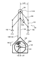
図1は、本発明の第1実施形態に係るディッピング装置10の概略斜視図であり、図2はディッピング装置10の使用形態を示している。このディッピング装置10は、使用者が負荷に抗して両手で操作する操作部例えば2つのグリップ12,12を、図2に示すように上下方向Aに往復移動させることで、上述した筋肉を動かしてトレーニングする装置である。
1.1. Overview of Dipping Device FIG. 1 is a schematic perspective view of a dipping device 10 according to a first embodiment of the present invention, and FIG. 2 shows a usage pattern of the dipping device 10. The dipping device 10 moves the above-described muscles by reciprocating an operation unit, for example, two
ディッピング装置10には、例えばT字型のベース基盤20に脚部22が垂直に立設され、脚部22に対して昇降可能な昇降部24を介して着座部26が固定されている。昇降部24は、着座部26の高さ位置を多段階または無段階で調整可能である。脚部22に対する昇降部24の高さ位置を調整する着座高さ調整装置として、例えば操作ピン23を昇降部24の図示しない係合孔に対して挿脱することにより高さを調整できる。
In the dipping device 10, for example, a
ベース基盤20上には、脚部22と離間した位置に支柱28が立設されている。この支柱28の頂部には、2つのグリップ12,12を、図2の上下方向に往復移動可能に支持する支持部材30が設けられている。
A
支持部材30は、支柱28の頂部に支持された揺動支点32(第1支点O1ともいう)を有する。支持部材30はさらに、長手方向の中間位置が揺動支点32により揺動自在に支持された揺動アーム34を含んでいる。
The
この揺動アーム34は、揺動支点32を備えた基部34Aと、基部34Aから二股に分かれて延在され、その自由端部に2つのグリップ12,12が支持された2つのアーム34B,34Bと、2つのアーム34B,34Bとは逆方向に基部34Aから延びるテール部34Cを含んでいる。つまり、2つのグリップ12,12は、揺動支点32を中心として、アーム34B,34Bにより揺動することで、図2の上下方向Bに移動操作可能である。なお、2つのグリップ12,12は、アーム34B,34Bに軸支されて、アーム34B,34Bに対して回動自在とすることができる。
The
この2つのグリップ12,12は負荷に抗して操作されるようになっていて、2つのグリップ12,12に負荷を作用させるためのウェイトが設けられている。本実施形態では、第1,第2のウェイト50,60が設けられている。
The two
第2のウェイト60は、テール部34Cの自由端側に配置される。この第2のウェイト60は、長さ調整装置62を介してテール部34Cに設けることができる。長さ調整装置62は、テール部34Cの自由端から第2のウェイト60までの長さを多段階または無段階で調整可能であり、周知の係合手段が採用される。また、第2のウェイト60自体の重量を変更可能としても良い。
The
第1のウェイト50は、例えば支柱28に設けられた回動支点52(第2支点O2ともいう)に回動可能に支持されている。第1のウェイト50は、回動支点52の周りで正逆方向の回動にされることで、回動支点52の周りのモーメントを可変する。
For example, the
第1のウェイト50自体を回動支点52に支持しても良いが、本実施形態では、一端が回動支点52に回動自在に支持され、他端が回動半径方向に延びるウェイト支持部材54をさらに有し、第1のウェイト50はウェイト支持部材54に取り付けることができる。また、第1のウェイト50は、ウェイト支持部材54に搭載される枚数を変更できる1または複数の単位重量プレート50Aとすることができる。なお、ウェイト支持部材54も荷重として機能する点では、単位重量プレート50Aと変わりはない。
Although the
この第1ウェイト50(またはウェイト支持部材54)を支持部材30に連結する連結部材40が設けられている。この連結部材40は、支持部材40と、第1のウェイト50またはウェイト支持部材54とを連結することで、2つのグリップ12,12の往復移動に連動させて、第1のウェイト50を正逆方向に回動させるものである。
A connecting
連結部材40は、揺動アーム34のテール部34Cに設けられた連結支点42と、連結支点42に回動自在に支持された連結金具44と、一端が連結金具44に連結され、他端が第1のウェイト50またはウェイト支持部材54に連結された紐状部材例えばワイヤー46とを含むことができる。なお、連結金具44はワイヤー46の長さを調整できる機能を有する。
The connecting
1.2.負荷可変動作
次に、図1に示すディッピング装置10において、2つのグリップ12,12の移動位置に従い負荷が可変される動作について、図3〜図5を参照して説明する。図3は、2つのグリップ12,12が上死点にある状態を示している。この上死点位置は、図示しないストッパにより設定される。2つのグリップ12,12が上死点にあるとき、2つのグリップ12,12は最大負荷(例えば15kg)に抗して移動操作される。図4は、図2に示すように、トレーニング中に使用者によって2つのグリップ12,12が例えば最高高さ位置に設定された時の状態を示している。このとき、2つのグリップ12,12は中間負荷(例えば7kg)に抗して移動操作される。図5は、トレーニング中に使用者によって2つのグリップ12,12が例えば最低高さ位置に設定された時の状態を示している。このとき、2つのグリップ12,12は最小負荷(例えば3kg)に抗して移動操作される。
1.2. Load Variable Operation Next, an operation in which the load is varied according to the movement positions of the two
これらのことを、図3〜図5中に示す力F、距離L、重量W及びモーメントMにより説明する。ただし、第1,第2のウェイト50,60の重量以外は無視するものとする。
These will be described with reference to force F, distance L, weight W and moment M shown in FIGS. However, the weights other than the weights of the first and
1.3.図3に示す状態での最大負荷
先ず、第1のウェイト50により、揺動アーム34を、第1支点O1を中心として時計廻り方向に回転させるモーメントM11は、第1のウェイト50の重量をW1とし、第2支点O2から第1のウェイト50の重心を通る荷重作用線(鉛直線)までの距離をL21とすると、M11=W1×L21となる。第1支点O1で支持された揺動アーム34と第1のウェイト50とは連結部材40で連結されているので、第1のウェイト50によるモーメントM11が揺動アーム34に作用する。
1.3. Maximum load in the state shown in FIG. 3 First, the moment M11 that rotates the
また、第2のウェイト60により、揺動アーム34を、第1支点O1を中心として時計廻り方向に回転させるモーメントM21は、第2のウェイト50の重量をW2とし、第1支点O1から第2のウェイト60の重心を通る荷重作用線(鉛直線)までの距離をL31とすると、M21=W2×L31となる。
The moment M21 that causes the
従って、第1,第2のウェイト50,60により、揺動アーム34を、第1支点O1を中心として時計廻り方向に回転させるトータルモーメントは、M11+M21となる。
Therefore, the total moment for rotating the
第1支点O1の一端側にこのトータルモーメント(M11+M21)が作用する揺動アーム34は、その他端側の2つのグリップ12,12を、そのトータルモーメント(M11+M21)の負荷に抗して押し下げるのに力F11(2つのグリップ12,12に作用するトータル力)を要する。この力F11は、第1支点O1から各グリップ12への力F11の作用線(鉛直線)までの距離をL11とすると、
F11=(M11+M21)/L11……(1)
となる。
The
F11 = (M11 + M21) / L11 (1)
It becomes.
ここで、図3では第1のウェイト50がほぼ水平に設定されるので、第2支点O2から第1のウェイト50の重心を通る荷重作用線(鉛直線)までの距離L21は最長に近い値となる。よって、第1のウェイト50に基づくモーメントM11は、最大に近い値となり、図4及び図5の後述するモーメントM12,M13よりも大きくなっている。
Here, in FIG. 3, since the
さらに、第1支点O1から第2のウェイト60の重心を通る荷重作用線(鉛直線)までの距離L31は、図4及び図5にて対応する距離L32,L33よりも大きい。よって、第2ウェイト60に基づくモーメントM21は、図4及び図5の後述するモーメントM222,M23よりも大きくなっている。
Furthermore, the distance L31 from the first fulcrum O1 to the load action line (vertical line) passing through the center of gravity of the
さらに、第1支点O1から2つのグリップ12,12までの距離L11は、図4及び図5に比べて短い。
Furthermore, the distance L11 from the first fulcrum O1 to the two
従って、上述の式(1)は、分母(M11+M21)が図4及び図5の場合よりも大きく、その分子(L11)が図4及び図5よりも小さいことから、力F11が最大になることは明らかである。 Therefore, the above formula (1) shows that the force F11 is maximized because the denominator (M11 + M21) is larger than those in FIGS. 4 and 5 and the numerator (L11) is smaller than those in FIGS. Is clear.
1.4.図4に示す状態での中間負荷
第1のウェイト50により、揺動アーム34を、第1支点O1を中心として時計廻り方向に回転させるモーメントM12は、第2支点O2から第1のウェイト50の重心を通る荷重作用線(鉛直線)までの距離をL22とすると、M12=W1×L22となる。
1.4. Intermediate load in the state shown in FIG. 4 The
また、第2のウェイト60により、揺動アーム34を、第1支点O1を中心として時計廻り方向に回転させるモーメントM22は、第1支点O1から第2のウェイト60の重心を通る荷重作用線(鉛直線)までの距離をL32とすると、M22=W2×L32となる。
In addition, the moment M22 that rotates the
第1支点O1の一端側にこのトータルモーメント(M12+M22)が作用する揺動アーム34は、その他端側の2つのグリップ12,12を、そのトータルモーメント(M12+M22)の負荷に抗して押し下げるのに力F12を要する。この力F12は、第1支点O1から各グリップ12への力F12の作用線までの距離をL12とすると、
F12=(M12+M22)/L12……(2)
となる。
The
F12 = (M12 + M22) / L12 (2)
It becomes.
ここで、図3と図4との比較から明らかなように、L12<L11であるからM12<M11となり、L22<L21であるからM22<M21となり、さらにL12>L11である。このため、式(2)は式(1)よりも分母が小さく分子が大きくなり、F12<F11となる。このように、図4に示す状態にて負荷に抗して2つのグリップ12,12を押し下げる力F12は、図3に示す状態での力F11よりも小さくなる。
Here, as apparent from the comparison between FIG. 3 and FIG. 4, since L12 <L11, M12 <M11, L22 <L21, M22 <M21, and L12> L11. Therefore, Formula (2) has a smaller denominator and a larger numerator than Formula (1), and F12 <F11. Thus, the force F12 that pushes down the two
1.5.図5に示す状態での最小負荷
第1のウェイト50により、揺動アーム34を、第1支点O1を中心として時計廻り方向に回転させるモーメントM13は、第2支点O2から第1のウェイト50の重心を通る荷重作用線(鉛直線)までの距離をL23とすると、M13=W1×L23となる。
1.5. The minimum load in the state shown in FIG. 5 With the
また、第2のウェイト60により、揺動アーム34を、第1支点O1を中心として時計廻り方向に回転させるモーメントM23は、第1支点O1から第2のウェイト60の重心を通る荷重作用線(鉛直線)までの距離をL33とすると、M23=W2×L33となる。
Further, the moment M23 that causes the
第1支点O1の一端側にこのトータルモーメント(M13+M23)が作用する揺動アーム34は、その他端側の2つのグリップ12,12を、そのトータルモーメント(M13+M23)の負荷に抗して押し下げるのに力F13を要する。この力F13は、第1支点O1から各グリップ12への力F12の作用線までの距離をL13とすると、
F13=(M13+M23)/L13……(3)
となる。
The
F13 = (M13 + M23) / L13 (3)
It becomes.
ここで、図4と図5との比較から明らかなように、L23<L22であるからM13<M12となり、L33<L32であるからM23<M22となる。また、図5の長さL13は図4の長さL12に比べて僅かに短くなるが、図5の長さL23,L33が図4の長さL22,L32よりも短くなる寸法差と比較すると充分に小さく、L13≒L12とみなすことができる。このため、式(3)は式(2)よりも分母が小さく分子はほぼ等しくなり、F13<F12<F11となる。このように、図5に示す状態にて負荷に抗して2つのグリップ12,12を押し下げる力F13は、図3及び図4に示す状態での力F11,F12よりも小さくなる。
Here, as apparent from the comparison between FIG. 4 and FIG. 5, since L23 <L22, M13 <M12, and since L33 <L32, M23 <M22. Further, the length L13 in FIG. 5 is slightly shorter than the length L12 in FIG. 4, but compared with the dimensional difference in which the lengths L23 and L33 in FIG. 5 are shorter than the lengths L22 and L32 in FIG. It is sufficiently small and can be regarded as L13≈L12. Therefore, Equation (3) has a smaller denominator than Equation (2), and the numerators are almost equal, and F13 <F12 <F11. Thus, the force F13 that pushes down the two
1.6.ディッピング装置の作用・効果
図2に示すように、2つのグリップ12,12を握った使用者がひじを上げる方向(図2参照)に操作すると、図5に示す状態から図4に示す状態に移行することになり、負荷は漸増することになる。つまり、図2に示す状態は、肩甲挙筋、僧帽筋上部、菱形筋、三角筋後部、上腕二頭筋などの筋肉を短縮または弛緩させ、かつ、大胸筋、広背筋、僧帽筋下部、三角筋前部、上腕三頭筋などの筋肉を伸張する方向に負荷が作用することになる。
1.6. Action and Effect of Dipping Device As shown in FIG. 2, when the user holding the two
これとは逆に、2つのグリップ12,12を握った使用者がひじを下げる方向に操作すると、図4に示す状態から図5に示す状態に移行することになり、負荷は漸減することになる。この状態では、図2に示す状態で短縮または弛緩した筋肉が伸張され、図2に示す状態で伸張された筋肉が短縮または弛緩される。従って、図4と図5の状態を交互に繰り返してトレーニングをする際に、上述した筋肉を効果的にほぐすことができる。しかも、使用者は図2に示す状態に設定するために負荷を利用しながら、図2に示す状態を解除するには負荷を少なくして、使用者への負担を軽減できる。従って、使用者は継続してこのトレーニングを行うことができる。
On the contrary, when the user holding the two
2.第2実施形態
本発明をハイプーリー装置に適用した第2実施形態について説明する。このハイプーリー装置は、上方に伸ばした両腕を屈伸させることで、大胸筋、広背筋、僧帽筋下部、三角筋後部、前鋸筋、菱形筋、三角筋、僧帽筋上部、肩甲挙筋などの筋肉を動かして、凝り固まった筋肉をほぐすのに効果的な装置である。
2. Second Embodiment A second embodiment in which the present invention is applied to a high pulley apparatus will be described. This high pulley device flexes and stretches both arms extended upwards, and the great pectoral muscle, latissimus dorsi, lower trapezius, posterior deltoid muscle, anterior sawtooth, rhomboid, deltoid, upper trapezius, shoulder It is an effective device to move the muscles such as the levator muscles and loosen the stiff muscles.
2.1.ハイプーリー装置の概要
図6及び図7は、本発明の第2実施形態に係るハイプーリー装置100の概略斜視図である。このハイプーリー装置100は、使用者が負荷に抗して両手で操作する操作部例えば2つのグリップ102,102を、図6に示す上死点と図7に示す下死点との間の使用可能範囲内で上下に往復移動させることで、上述した筋肉を動かしてトレーニングする装置である。
2.1. Overview of High Pulley Device FIGS. 6 and 7 are schematic perspective views of a
このハイプーリー装置100では、図示していないが、着座部と、着座部に着座された使用者の膝を押さえる膝押え部を有し、着座部に着座した使用者により2つのグリップ102,102が上下に操作される。なお、着座部及膝押さえ部の高さも、使用者に応じて調整可能である。
Although not shown in the drawings, the
図6及び図7は、負荷可変動作に必要な部材のみを示し、他の部材は省略されている。図6及び図7において、ハイプーリー装置100は、操作部である2つのグリップ102,102を往復移動可能に支持する支持部材110と、回動支点122に回動可能に支持され、正逆方向の回動により回動支点122の周りのモーメントを可変するウェイト120と、支持部材110とウェイト120とを連結して、2つのグリップ102,102の往復移動に連動させてウェイト120を正逆方向に回動させる連結部材130とを有する。
6 and 7 show only members necessary for the load variable operation, and other members are omitted. 6 and 7, the
支持部材110は、図6に示すように、複数例えば6つの支点112A〜112Fと、複数例えば6本のリンク114A〜114Fを含む平行リンク機構116を、支柱104の上端部に有する。なお、本実施形態の平行リンク機構116は、2つの4節回転連鎖を含んでいる。つまり、支柱104に固定された固定リンク104Aの両端の支点112A,112Bを中心として、第1のリンク対114A,114B及び第2のリンク対114D,114Eが、リンク114C,114Fにより規制されながら平行移動する。2つのグリップ102,102は、平行リンク機構116に直接取り付けても良いが、これに限らず、平行リンク機構116により案内される水平バー(図示せず)に取り付けられても良い。こうすると、2つのグリップ102,102が一体として、平行リンク機構116により平行移動案内される。
As shown in FIG. 6, the
ハイプーリー装置100の下部には、回動支点122を中心として正逆方向に回動する第1のプーリー124をさらに有する。そして、本実施形態では、ウェイト120は第1のプーリー124の回動支点122から偏心した位置に重心が設けられるように、第1のプーリー124に例えばスポーク120Aを介して取り付けられている。
The lower portion of the
連結部材130は、下端が第1のプーリー124に連結固定されて、第1のプーリーの回動に従い第1のプーリーに巻き取られる紐状部材例えばワイヤー132を含む。このワイヤー132の上端は、例えば支点112Bと同軸で配置された第2のプーリー138に巻回されて、平行リンク機構116の複数のリンク114A〜114Fの一つである例えばリンク114Aに連結されている。ワイヤー132がリンク114Aに連結される位置は、複数の支点112A〜122Fから離れた位置である。より詳しくは、リンク114Aに連結支点134を介して回動自在な連結金具136に、ワイヤー132の上端が連結されている。
The connecting
2.2.負荷可変動作
図6において、プーリー124をウェイト120により反時計廻り方向に回動させるように作用するモーメントM11は、回動支点122からウェイト120の重心を通る荷重作用線(鉛直線)までの距離をL21とすると、M11=W×L21となる。このモーメントM11は、連結部材110を介して平行リンク機構116に作用する。よって、モーメントM11は、平行リンク機構116に支持された2つのグリップ102,102を下方向に移動するのに抗する負荷となる。
2.2. In FIG. 6, the moment M11 that acts to rotate the
図7でも同様に、プーリー124をウェイト120により反時計廻り方向に回動させるように作用するモーメントM12は、回動支点122からウェイト120の重心を通る荷重作用線(鉛直線)までの距離をL22とすると、M12=W×L22となる。このモーメントM12もまた、平行リンク機構116に支持された2つのグリップ102,102を下方向に移動するのに抗する負荷となる。
Similarly in FIG. 7, the moment M12 that acts to rotate the
このように、2つのグリップ102,102の操作位置に応じて、回動支点122からウェイト120の重心を通る荷重作用線(鉛直線)までの距離が変化されて、2つのグリップ102,102を下方向に移動するのに抗する負荷が可変されることが分かる。
As described above, the distance from the
この可変モーメントは、支点122から半径方向に延びてプーリー124にウェイト120を保持するスポーク120Aが水平となった時である。このとき、回動支点122からウェイト120の重心を通る荷重作用線(鉛直線)までの距離が最大となるからである。このモーメントが最大となる位置は、図6に示すグリップ102の上死点と図7に示すグリップ102の下死点との間に存在する。
This variable moment is when the
一方、図6において、2つのグリップ102,102を、モーメントM11の負荷に抗して押し下げるのに力F11(2つの2つのグリップ102,102に作用するトータル力)を要する。この力F11は、支点112A,112Bを通る鉛直線から各グリップ102への力F11の作用線までの距離をL11とすると、
F11=M11/L11……(4)
となる。
On the other hand, in FIG. 6, a force F11 (total force acting on the two two
F11 = M11 / L11 (4)
It becomes.
同様に、図7において、2つのグリップ102,102を、モーメントM12の負荷に抗して押し下げるのに力F12は、支点112A,112Bを通る鉛直線から各グリップ102への力F12の作用線までの距離をL12とすると、
F12=M12/L12……(5)
となる。
Similarly, in FIG. 7, the force F <b> 12 for pushing down the two
F12 = M12 / L12 (5)
It becomes.
ここで、図6及び図7に示す装置を簡易モデル化した図8を参照して、負荷可変動作について説明する。図8には、2つのグリップ102,102の高さ位置が異なる3つの位置H1,H2,H3に設定された状態が示されている。図8の実線で示す位置H1は図6に近い位置であり、使用者の腕が伸びきった状態での操作位置である。この位置H1から位置H2に2つのグリップ102,102を引き下げると、ウェイト120によるモーメントは漸増し、ウェイト120を保持するスポーク120Aがほぼ水平となる最大モーメント発生位置付近となる。図8の簡易モデルでは、位置H1での負荷に対して、位置H2での負荷は50%ほど重くなった。ただし、位置H1では、使用者の腕はほぼ直角に曲がり、最も力を発揮できる状態であるので、使用者への負担は少ない。
Here, the variable load operation will be described with reference to FIG. 8 which is a simplified model of the apparatus shown in FIGS. FIG. 8 shows a state in which the height positions of the two
この位置H2から位置H3に2つのグリップ102,102をさらに引き下げると、ウェイト120よるモーメントは漸減する。よって、位置H2を境にして、2つのグリップ102,102を引き下げても引き上げても負荷が漸減する。
When the two
腕が伸びきった位置H1では、三角筋、僧帽筋上部、肩甲挙筋などの筋肉を充分に短縮または弛緩させることができ、かつ、大胸筋、広背筋、僧帽筋下部、三角筋後部、前鋸筋、菱形筋などの筋肉を伸張させることができる。一方、腕が縮まった位置H3では、位置H1の状態で短縮または弛緩した筋肉が伸張され、位置H1の状態で伸張された筋肉が短縮または弛緩される。よって、この動作を繰り返し行うことで、上述した筋肉が充分にほぐされる。 In the position H1 where the arm is fully extended, muscles such as the deltoid muscle, the upper part of the trapezius, and the levator scapula can be sufficiently shortened or relaxed, and the greater pectoral muscle, the latissimus dorsi, the lower part of the trapezius, the triangle Muscles such as the posterior muscle, the front saw blade, and the rhomboid can be stretched. On the other hand, at the position H3 where the arm is contracted, the muscle shortened or relaxed in the state of the position H1 is stretched, and the muscle stretched in the state of the position H1 is shortened or relaxed. Therefore, by repeating this operation, the muscles described above are sufficiently loosened.
ここで、距離L11,L12等の距離Lは、2つのグリップ102,102の位置に応じて平行リンク機構116に従って可変される。2つのグリップ102,102を押し下げる力Fは、モーメントMが仮に一定であれば、距離Lが大きくなるほど小さくて済む。本実施形態では、距離Lは小さくなればモーメントMも小さくなり、モーメントMが大きくなれば距離Lも大きくなるので、2つのグリップ102,102を押し下げるのに要する負荷が過大に増大することはない。
Here, the distance L such as the distances L11 and L12 is varied according to the parallel link mechanism 116 in accordance with the positions of the two
3.第3実施形態
本発明をプルオーバー装置に適用した第3実施形態について説明する。このプルオーバー装置は、上方に伸ばした両腕を前後に移動させることで三角筋、僧帽筋、菱形筋、大胸筋、前鋸筋、三角筋前部、腹直筋、外腹斜筋などの筋肉や肩関節を動かして、凝り固まった筋肉や間接をほぐすのに効果的な装置である。
3. Third Embodiment A third embodiment in which the present invention is applied to a pullover device will be described. This pullover device moves the upper and lower arms back and forth to move the deltoid, trapezius, rhomboid, pectoralis, anterior saw, the anterior abdominis, rectus abdominis, and external obliques It is an effective device to loosen up stiff muscles and indirects by moving the muscles and shoulder joints.
3.1.プルオーバー装置の概要
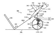
図9及び図10は、本発明の第3実施形態に係るプルオーバー装置200の概略斜視図である。このプルオーバー装置200は、使用者が負荷に抗して両腕の前腕部分で操作する操作部例えば操作バー202を、図9及び図10に示す使用可能範囲内で前後に往復移動させることで、上述した筋肉や肩関節を動かしてトレーニングする装置である。
3.1. Outline of Pullover Device FIGS. 9 and 10 are schematic perspective views of a
プルオーバー装置200は、前端が上方を向くように傾斜した着座部204と、この着座部204より斜め上方に延びる背もたれ部206を有する。使用者は、着座部204に着座すると共に、背もたれ部206に背中を合わせて、仰向けにて傾斜状態で着座する。着座部204及び背もたれ部206を挟んだ両側には、2本の支柱(図では1本のみ図示)210が設けられている。
The
操作部である操作バー202を前後方向に往復移動可能に支持する支持部材220が設けられている。この支持部材220は、2本の支柱210,210(図では1本のみ図示)の上端にそれぞれ設けられた2つの揺動支点222(図では1つのみ図示)と、この2つの揺動支点222を中心として回動する2本のアーム224(図では1本のみ図示)とを含む。操作バー202は2本のアーム224間に連結され、この各部材202,224,224が全体としてコ字型(チャネル型)をなしている。
A
プルオーバー装置200はさらに、回動支点232に回動可能に支持され、正逆方向の回動により、回動支点232の周りのモーメントを可変するウェイト230を備えている。本実施形態でも、第2実施形態と同様に、プルオーバー装置200の下部には、回動支点232を中心として正逆方向に回動する第1のプーリー234を有する。そして、本実施形態では、ウェイト230は第1のプーリー234の回動支点232から偏心した位置に重心が設けられるように、第1のプーリー234にスポーク230Aを介して取り付けられている。
The
プルオーバー装置200はさらに、支持部材220とウェイト230とを連結して、操作部バー202の往復移動に連動させてウェイト230を正逆方向に回動させる連結部材240を備えている。この連結部材240は、下端が第1のプーリー234に連結固定されて、第1のプーリー234の回動に従い第1のプーリー234に巻き取られる紐状部材例えばワイヤー242を含む。このワイヤー242の上端は、第2のプーリー250に巻回されて、支持部材220の一方のアーム224に連結されている。ワイヤー242は、支柱210の上端の支点222から離れた位置にて、アーム224に連結されている。
The
3.2.負荷可変動作
図9において、プーリー234をウェイト230により時計廻り方向に回動させるように作用するモーメントM11は、回動支点232からウェイト230の重心を通る荷重作用線(鉛直線)までの距離をL21とすると、M11=W×L21となる。このモーメントM11は、連結部材240を介してアーム224に作用する。よって、モーメントM11は、アーム224に支持された操作バー202を図示左側に移動するのに抗する負荷となる。
3.2. In FIG. 9, the moment M <b> 11 that acts to rotate the
図10でも同様に、プーリー234をウェイト230により時計廻り方向に回動させるように作用するモーメントM22は、回動支点232からウェイト230の重心を通る荷重作用線(鉛直線)までの距離をL22とすると、M12=W×L22となる。このモーメントM12もまた、アーム224に支持された操作バー202を図示左側に移動するのに抗する負荷となる。
Similarly in FIG. 10, the moment M22 that acts to rotate the
このように、操作バー202の操作位置に応じて、回動支点232からウェイト230の重心を通る荷重作用線(鉛直線)までの距離が変化されて、操作バー202を図示左側に移動するのに抗する負荷が可変されることが分かる。
As described above, the distance from the
この可変モーメントは、支点232から半径方向に延びてプーリー234にウェイト230を保持するスポーク230Aが水平に近い時(図10)ほど大きい。このとき、回動支点232からウェイト230の重心を通る荷重作用線(鉛直線)までの距離が増大するからである。よって、M12>M11となる。
This variable moment increases as the
図9の状態から図10に示す状態に向けて使用者が両腕を背中方向に後退させる際には、モーメントMによる負荷が漸増され、図10に示す位置にて大きなモーメントが発生する。よって、図10に示す位置にて位置付近では、負荷を利用して筋肉や肩関節をほぐすことが可能となる。つまり、図10に示す位置付近では、三角筋、僧帽筋、菱形などの筋肉が短縮または弛緩され、大胸筋、前鋸筋、三角筋前部、腹直筋、外腹斜筋などの筋肉が伸張される。一方、操作バー202を負荷に抗して力F11,F12等の力Fで押し戻すときには、モーメントMは漸減するので、負荷も漸減する。よって、操作バー202を前後動させる操作を繰り返し行なう際に、操作バー202を押し戻す時の負荷が漸減されるので、使用者の負担を軽減できる。
When the user retreats both arms in the back direction from the state of FIG. 9 to the state shown in FIG. 10, the load due to the moment M is gradually increased, and a large moment is generated at the position shown in FIG. Therefore, in the vicinity of the position at the position shown in FIG. 10, it is possible to loosen muscles and shoulder joints using the load. That is, in the vicinity of the position shown in FIG. 10, muscles such as the deltoid, trapezius, and rhombus are shortened or relaxed, such as the pectoralis major muscle, the anterior sawtooth, the anterior part of the deltoid, the rectus abdominis, and the external oblique muscle. Muscles are stretched. On the other hand, when the
図9において、操作バー202を、モーメントM11の負荷に抗して移動させるのに力F11を要する。この力F11は、揺動支点222を通る水平線から操作バー202への力F11の作用線までの距離をL11とすると、上述の式(4)の通りとなる。
In FIG. 9, force F11 is required to move the
同様に、図7において、操作バー202をモーメントM12の負荷に抗して移動させるのに力F12は、揺動支点222を通る水平線から操作バー202への力F12の作用線までの距離をL12とすると、上述の式(5)の通りとなる。
Similarly, in FIG. 7, the force F <b> 12 moves the
距離L11,L12等の距離Lは、アーム224が垂直になった時に最大となる。図10の状態からアーム224が垂直となるまでは、モーメントMは漸減し距離Lが漸増するので、力Fも漸減する。アーム224が垂直となる位置から図9に示す状態に移行するには、距離Lは漸増するがモーメントMが漸減するので、力Fが増大することはない。
The distance L such as the distances L11 and L12 becomes maximum when the
4.第4実施形態
本発明をレッグプレス装置に適用した第4実施形態について説明する。このレッグプレス装置は、斜め上方に伸ばした両脚を屈伸させることで大腰筋、内転筋群、大腿四頭筋、二頭筋、大腿筋膜腸筋、大殿筋などの筋肉を動かして、凝り固まった筋肉をほぐすのに効果的なトレーニング装置である。
4). Fourth Embodiment A fourth embodiment in which the present invention is applied to a leg press apparatus will be described. This leg press device moves muscles such as the psoas major, adductor muscles, quadriceps, biceps, femoral fascia, and gluteal muscles by flexing and stretching both legs extended obliquely upward, It is an effective training device for relaxing stiff muscles.
4.1.レッグプレス装置の概要
図11及び図12は、本発明の第4実施形態に係るレッグプレス装置300の概略斜視図である。このレッグプレス装置300は、使用者が負荷に抗して両脚で操作する操作部例えばフットペダル302を、図11及び図12に示す使用可能範囲内で上下に往復移動させることで、上述した筋肉を動かしてトレーニングする装置である。
4.1. Outline of Leg Press Device FIGS. 11 and 12 are schematic perspective views of a
このレッグプレス装置300には、前端が上方を向くように傾斜した着座部304と、この着座部304より斜め上方に延びる背もたれ部306を有する。使用者は、着座部304に着座すると共に、背もたれ部306に背中を合わせ、フットペダル302に足の裏をつけて、仰向けにて傾斜状態で着座する。着座部304及び背もたれ部306は、例えば直角三角形のフレーム308の斜辺308Aに支持されている。
The
図11及び図12において、レッグプレス装置300は、操作部であるフットペダル302を往復移動可能に支持する支持部材310と、回動支点322に回動可能に支持され、正逆方向の回動により回動支点322の周りのモーメントが可変されるウェイト320と、支持部材310とウェイト320とを連結して、フットペダル302の往復移動に連動させてウェイト320を正逆方向に回動させる連結部材330とを有する。
11 and 12, the
支持部材310は、複数例えば4つの支点312A〜312Dと、複数例えば3本のリンク314A〜314Cを含む平行リンク機構316を有する。この平行リンク機構316は、例えばフレーム308の斜辺308A等の固定部に設けた2つの支点312A,312Bを中心にリンク314A,314Bがリンク314Cに規制されながら平行移動する4節回転連鎖を含んでいる。
The
フットペダル302は、リンク314Cに対して直角になるように、フレーム318に支持され、平行に移動案内される。
The
フレーム308は、回動支点322を中心として正逆方向に回動するプーリー324をさらに有する。そして、本実施形態では、ウェイト320はプーリー324の回動支点322から偏心した位置に重心が設けられるように、プーリー324に例えばスポーク320Aを介して取り付けられている。
The
連結部材330は、下端がプーリー324に連結固定されて、第1のプーリーの回動に従いプーリー324に巻き取られる紐状部材例えばワイヤー332を含む。このワイヤー332の上端は、リンク314Bと一体で支点312Bの廻りで回動するリンク314Dの自由端側にて回動自在に取り付けられた連結金具334に連結されている。
The connecting
4.2.負荷変動動作
図11に示す状態での発生モーメントM11=W×L21であり、図12に示す状態での発生モーメントM12=W×L22であり、L21<L22であるからM11<M12となることは、図9及び図10と同様である。
4.2. Load fluctuation operation The generated moment M11 = W × L21 in the state shown in FIG. 11, the generated moment M12 = W × L22 in the state shown in FIG. 12, and L21 <L22, so that M11 <M12. 9 and 10 are the same.
図11の状態から図12に示す状態に向けて移行するように使用者が両脚を曲げる際には、モーメントMによる負荷が漸増され、図12に示す位置にて大きなモーメントが発生する。よって、図12に示す位置にて位置付近では、負荷を利用して筋肉や肩関節をほぐすことが可能となる。つまり、図12に示す位置付近では、大腰筋、内転筋群が短縮または弛緩され、大腿四頭筋、二頭筋、大腿筋膜腸筋、大殿筋が伸張される。 When the user bends both legs so as to shift from the state of FIG. 11 to the state shown in FIG. 12, the load due to the moment M is gradually increased, and a large moment is generated at the position shown in FIG. Therefore, in the vicinity of the position at the position shown in FIG. 12, it is possible to loosen muscles and shoulder joints using the load. That is, in the vicinity of the position shown in FIG. 12, the psoas major and adductor muscles are shortened or relaxed, and the quadriceps, biceps, femoral fascia, and gluteal muscles are stretched.
一方、フットペダル302を負荷に抗して力F11,F12等の力Fで押し戻すときには、モーメントMは漸減するので、負荷も漸減する。よって、フットペダル302を前後動させる操作を繰り返し行なう際に、フットペダル302を押し戻す時の負荷が漸減されるので、使用者の負担を軽減できる。
On the other hand, when the
図11において、フットペダル302を、モーメントM11の負荷に抗して移動させるのに力F11は上述の式(4)の通りとなる。図12において、フットペダル302を、モーメントM12の負荷に抗して移動させるのに力F12は上述の式(5)の通りとなる。
In FIG. 11, the force F11 is as shown in the above-described equation (4) for moving the
ここで、距離L11,L12等の距離Lは、フットペダル302の位置に応じて平行リンク機構316に従って可変される。フットペダル302を押し上げる力Fは、モーメントMが仮に一定であれば、距離Lが大きくなるほど小さくて済む。本実施形態では、距離Lは小さくなればモーメントMも小さくなり、モーメントMが大きくなれば距離Lも大きくなるので、フットペダル302を押し上げるのに要する負荷が過大に増大することはない。
Here, the distance L such as the distances L11 and L12 is varied according to the
なお、本実施形態では、距離L11,L12等の距離Lは、フットペダル302の高さ位置を設定することになる。この際、使用者が脚を伸ばした時のフットペダル302の位置は低い一方で、使用者が脚を曲げた時のフットペダル302の位置は高くなる。この高低位置は、人間の脚の自然な動きにフィットしたものとなる。よって、レッグプレス装置300の支持部材310として平行リンク機構316を採用することは、使用者の動きに合わせてフットペダル302の高さを調整できる点でも効果がある。
In the present embodiment, the distance L such as the distances L11 and L12 sets the height position of the
5.第5実施形態
本発明をディッピング装置に適用した第5実施形態について説明する。このディッピング装置は、上述した負荷可変機能に加えて、操作部の高さ位置調整機能と操作部である第1,第2のグリップ間隔を可変する機能を有する。
5. Fifth Embodiment A fifth embodiment in which the present invention is applied to a dipping apparatus will be described. In addition to the load variable function described above, this dipping device has a function of adjusting the height position adjusting function of the operation unit and a function of changing the first and second grip intervals as the operation unit.
5.1.ディッピング装置の概要
図13は、本発明の第5実施形態に係るディッピング装置400の概略説明図であり、同図において図1に示す装置と同一機能を有する部材については、図1と同一符号を付してその説明を省略する。
5.1. Outline of Dipping Device FIG. 13 is a schematic explanatory view of a dipping device 400 according to a fifth embodiment of the present invention. In FIG. 13, members having the same functions as those shown in FIG. A description thereof will be omitted.
図13において、このディッピング装置400も、操作部である2つのグリップ12を往復移動可能に支持する支持部材40と、回動支点52に回動可能に支持され、正逆方向の回動により、回動支点の周りのモーメントを可変する少なくとも一つウェイト420と、支持部材30とウェイト420とを連結して、グリップ12の往復移動に連動させてウェイト420を正逆方向に回動させる連結部材40とを備えている点で、図1のディッピング装置10と共通している。図13では、回動支点52に回動自在なウェイト支持部材410を有し、ウェイト420が搭載されたウェイト支持部材410が連結部材40と連結されている。
In FIG. 13, this dipping device 400 is also rotatably supported by a
図14及び図15は、2つのグリップ12が上死点及び下死点となる状態のウェイト420の周辺部を図示している。2つのグリップ12が上死点付近では、図14に示すように、ウェイト420はほぼ水平状態となり、回動支点52の周りのモーメントが最大となり、2つのグリップ12を押し下げる時の負荷も最大となる。一方、2つのグリップ12が下死点付近では、図15に示すように、ウェイト420はほぼ垂直状態となり、回動支点52の周りのモーメントが最小となり、2つのグリップ12を押し下げる時の負荷も最小となる。このようにすると、少なくとも一つのウェイト420を用いながら負荷の可変範囲が拡大される。
14 and 15 illustrate the peripheral portion of the
5.2.グリップ高さ調整
図13において、このディッピング装置400は、グリップ高さ調整装置29が設けられている。図1のディッピング装置10の支柱28は、図13のディッピング装置400では、支柱28Aと、支柱28Aに対して昇降可能な昇降部28Bとに分離されている。そして、支柱28Aに対する昇降部28Bの高さ位置を調整するグリップ高さ調整装置29は、上方付勢手段としての例えば油圧シリンダー29Aと、操作ピン29Bと、操作ピン29Bが挿入される複数の係合孔29C(図13では一つのみ図示)とを含む。油圧シリンダー29Aは、一端がフレームに固定されたロッド29A1を駆動するシリンダー29A2が、昇降部28Bに固定され、昇降部28Bを常時上昇方向に移動付勢している。ロッド29A1が挿脱されることで、支柱28Aに対して昇降部28Bが昇降可能され、かつ、操作ピン29Bをいずれかの係合孔29Cに挿通させることで、昇降部28Bの高さ位置が決まる。
5.2. Grip Height Adjustment In FIG. 13, the dipping device 400 is provided with a grip
ここで、本実施形態では、揺動支点32、支持部材30及び回動支点52は、昇降部28Bに支持されている。回動支点52には、ウェイト420を搭載するウェイト支持部材410が支持され、このウェイト支持部材410は連結部材40により支持部材30に連結されているので、これらの各部材30,32,40,52,410,420は、その位置関係を維持したまま昇降部28Bと共に昇降されることになる。従って、グリップ高さ調整装置29により昇降部28Bを昇降させても、他を調整する必要はない。
Here, in this embodiment, the
本実施形態では、着座部26が着座高さ調整装置23にて調整されると共に、グリップ12がグリップ高さ調整装置29により調整されるので、使用者は、着座位置とグリップ位置との双方の高さを調整して、使用者個々の体格にフィットした姿勢でトレーニングを行うことができる。これにより、トレーニング効果を増大させることができる。
In this embodiment, the
これに対して、支柱に支持されたプーリーを介して、フレームに昇降自在に案内されたウェイトを移動させる従来のトレーニング装置では、プーリーを昇降させてもウェイトは移動しない。よって、プーリーを昇降させると、ワイヤーが緩み、または緊張されてしまう。このため、この種の装置では高さ調整を行うとワイヤー長さを調整する必要がある。本実施形態のように、ウェイト420を昇降部28Bに回動自在に支持することで、グリップ12の高さ地位も調整できるようになった。
On the other hand, in the conventional training apparatus that moves the weight guided so as to be movable up and down through the pulley supported by the support column, the weight does not move even when the pulley is moved up and down. Therefore, when the pulley is raised and lowered, the wire is loosened or strained. For this reason, in this type of apparatus, it is necessary to adjust the wire length when the height is adjusted. As in the present embodiment, the height position of the
なお、操作部の高さ調整は、ディッピング装置に限らず、支持部材とウェイトの回動支点とを昇降部に支持させた構造であれば、他のトレーニング装置にも同様に適用可能である。 The height adjustment of the operation unit is not limited to the dipping device, but can be applied to other training devices as long as the support member and the pivot point of the weight are supported by the lifting unit.
5.3.ウェイトの支持構造
図13〜図15に示すウェイト支持部材410に搭載されるウェイト420の一例を図16(A)(B)に示す。図16(A)に示すように、平面視で例えば四角形状のウェイト420にはスリット状の切欠部424が形成されると共に、ウェイト支持部材410に対する被支持部422が切欠部424により細幅状に確保されている。被支持部422は、図16(B)に示すように縦断面が回転対象形である例えば正方形となっている。
5.3. Weight Support Structure An example of the
一方、図13〜図15に示すウェイト支持部材410には、図17及び図18に示すように、少なくとも一つ例えば3つのウェイト支持部410A〜410Cが形成されている。3つのウェイト支持部410A〜410Cは、ウェイト420の被支持部422を支持可能なように、例えば溝形状に形成されている。
On the other hand, as shown in FIGS. 17 and 18, at least one, for example, three
ここで、ウェイト420の被支持部422の縦断面が正方形であることから、3つのウェイト支持部410A〜410Cのいずれに対しても、図17に示すようにウェイト420を縦方向に向けて搭載することと、図18に示すようにウェイト420を横方向に向けて搭載することとを選択できる。このように、一つのウェイト支持部に対してウェイト420の姿勢を異ならせて搭載することで、ウェイト420の重心位置が異なるため、回動支点52の周りのモーメントを変更でき、それにより負荷を変更できる。
Here, since the longitudinal section of the supported
さらに、複数のウェイト支持部410A〜410Cの中から一以上を用いて選択的にウェイト420を搭載することによっても、ウェイト420の重心位置が異なるため、回動支点52の周りのモーメントを変更でき、それにより負荷を変更できる。こうして、ウェイト420の取り付け姿勢、取り付け位置、取り付け個数を選択することで、負荷可変範囲が飛躍的に増大する。
Further, by selectively mounting one or
さらに、ウェイト420には、図16(A)に示すように切欠部424が形成されており、この切欠部424は昇降部28B(もしくは図1の支柱28)とは干渉しない逃げ部として機能する。従って、側面視において、ウェイト420の回動軌跡が昇降部28Bと干渉するような場合でも、ウェイト420は切欠部424によって昇降部28Bと干渉することがない。このことは、ウェイト420の回動半径を小さくしてトレーニング装置を小型化させるのに大いに寄与する。
Further, the
図19は、図13〜図19に示す実施形態のうち、ウェイト支持部材及びウェイトを変更した変形例を示している。図19に示す実施形態では、回動支点52に回動自在な例えば一対のウェイト支持部材412,412を有し、この一対のウェイト支持部材412,412にはウェイト支持棒414,414が固定されている。ウェイト426は、各ウェイト支持棒414に挿通可能な孔を有するリング形状に形成されている。
FIG. 19 shows a modified example in which the weight support member and the weight are changed in the embodiment shown in FIGS. In the embodiment shown in FIG. 19, for example, a pair of
このウェイト支持部材412,412が回動支点52の廻りで回動しても、ウェイト支持部材412,412よりも外側にそれぞれ設けられたウェイト支持棒414,414に搭載されたウェイト426,426は、昇降部28B(もしくは図1の支柱28)と干渉することはない。しかも、ウェイト支持棒414,414に支持されるウェイト426の数を変更することで、重量及び重心位置が変更され、回動支点52の廻りの負荷モーメントを変更できる。
Even if the
なお、図19では、連結部材40が図1及び図13に示すワイヤーや連結金具ではなく、少なくとも1本(図19では2本)のリンク40A,40Bで形成されている。このように、プーリー等を用いない第1,第5実施形態等では、ウェイトまたはウェイト支持部材と支持部材40を連結する連結部材40としては、両端が回動自在なリンクとしても良い。
In FIG. 19, the connecting
5.4.グリップ間隔可変
図13に示すディッピング装置400は、グリップ間隔調整装置430A(430B)を有する。このグリップ間隔調整装置430A(430B)は、使用者が負荷に抗して2つのグリップ(広義には第1,第2の操作部)を移動操作することにより、身体の筋肉または関節を動かすトレーニング装置に有効である。間隔が調整される2つの操作部とは、上述した第1,第2実施形態に示すものの他、負荷に抗して両脚を開脚するインナーサイ装置等にも適用できる。
5.4. Grip Interval Variable A dipping device 400 shown in FIG. 13 includes a grip
図20(A)(B)はグリップ間隔調整装置430Aがそれぞれ狭い間隔W1及び広い間隔W2に調整した状態をそれぞれ平面視で示し、図21はグリップ間隔調整装置430Aの側面図である。このグリップ間隔調整装置430Aは、2つのグリップ12,12がそれぞれ固定され、軸心周りに自転可能に支持された第1,第2の自転軸部432A,432Bと、第1,第2の自転軸部432A,432Bにそれぞれ固定された第1,第2の移動体434A,434Bと、第1,第2の移動体434A,434Bに設けられ、第1,第2の自転軸432A,432Bを支点として、第1,第2の移動体434A,434Bを互いに逆方向に実質的に同一回転角度だけ回転同調させる同調機構460と、を有する。
FIGS. 20A and 20B show the state in which the grip
グリップ間隔調整装置430Aは、第1,第2の自転軸432A,432Bのいずれか一方を支点軸として、その支点軸に連結された一方のグリップ12を回転操作することで、2つのグリップ12,12を、2つのグリップ12,12間を2分する中心線Lに対して線対称で移動させて、2つのグリップ12,12の間隔を調整するものである。
The grip
同調機構260は、第1,第2の移動体434A,434Bに支持されて交差して配置された第1,第2のリンク446A,446Bを有する。なお、第1,第2の自転軸部432A,432Bは、図21に示すように、支持部材30の基部34A上に固定された固定板34Dに自転可能に支持されている。
The tuning mechanism 260 includes first and
第1の移動体434Aには、第1,第2の支点450,452が離間して配置され、第2の移動体434Bには、第3,第4の支点454,456が離間して配置されている。第1のリンク446Aの一端が第1の移動体434Aに設けられた第1の支点450に回動自在に支持され、第1のリンク446Aの他端が第2の移動体434Bに設けられた第4の支点456に回動自在に支持されている。同様に、第2のリンク446Bの一端が第2の移動体434Aに設けられた第3の支点に回動自在に支持され、第2のリンク446Bの他端が第1の移動体434Aに設けられた第2の支点452に回動自在に支持されている。
First and
まず、2つのグリップ12,12の間隔が、図20(B)に示すように広い間隔W2から図20(A)に示す狭い間隔W1になるように調整する動作について説明する。このとき、第1の自転軸部432AがA2方向に、第2の自転軸部432BがA2方向とは逆のB2方向に自転される。この一対の自転方向A2,B2を第2自転対方向と称する。この自転操作は、2つのグリップ12,12を第1,第2の自転軸部432A,432Bを中心として第2自転対方向A2,B2に回動させればよい。
First, an operation for adjusting the distance between the two
こうすると、第1の支点450と第3の支点454との間の距離が増大し、第2の支点452と第4の支点456との間の距離が減少して、2つのグリップ12,12の間隔が広い間隔W2から狭い間隔W1に向いて可変される。
As a result, the distance between the
しかも、2つのグリップ12,12の回動量が異なるか、あるいは2つのグリップ12,12の一方のみが回動されたときでも、このグリップ間隔調整装置430Aは、2つのグリップ12,12を線対象で移動させることができる。仮に、図20(B)の右側のグリップ12のみがA2方向に回動されたとする。こうすると、第1の自転軸部432A、第1の移動体434A、第1,第2のリンク446A,446B、第1,第3の支点450,452が一体で回動される。
Moreover, even when the rotation amounts of the two
そうすると、第1のリンク446Aは第4の支点456を引っ張り、第2のリンク446Bは第3の支点454を押動するので、第2の移動体434Bが第2の軸部432BをB2方向に回動させることになる。このため、2つのグリップ12,12は線対象で移動される。
Then, since the
次に、2つのグリップ12,12の間隔が、図20(A)に示すように狭い間隔W1から図20(B)に示す広い間隔W2になるように調整する動作について説明する。このとき、第1の自転軸部432AがA1方向に、第2の自転軸部432BがA1方向とは逆のB1方向に自転される。この一対の自転方向A1,B1を第1自転対方向と称する。この自転操作は、2つのグリップ12,12を第1,第2の自転軸部432A,432Bを中心として第1自転対方向A1,B1に回動させればよい。
Next, an operation for adjusting the distance between the two
こうすると、第1の支点450と第3の支点454との間の距離が減少し、第2の支点452と第4の支点456との間の距離が増大して、2つのグリップ12,12の間隔が狭い間隔W1から広い間隔W2に向いて可変される。しかも、2つのグリップ12,12の回動量が異なるか、あるいは2つのグリップ12,12の一方のみが回動されたときでも、このグリップ間隔調整装置430Aは、2つのグリップ12,12を中心線Lに対して線対象で移動させることができる。
As a result, the distance between the
なお、2つのグリップ12,12を第1,第2の自転軸部432A,432Bの廻りに回動させるには、第1,第2の自転軸部432A,432B、第1,第2の移動体434A,434B及び第1,第2のリンク446A,446Bが一体で回動されることになる。これらが一体で回動するには摩擦抵抗力が作用するので、この摩擦抵抗力を利用して2つのグリップ12,12は所望の間隔幅にて摩擦力で保持でき、無段階で間隔幅を調整できる。これに代えて、2つのグリップ12,12の間隔幅を複数段階の各可変幅位置で保持する周知の係合手段を付加してもよい。
In order to rotate the two
5.5.グリップ間隔可変の他の例
図22(A)(B)は、図20(A)(B)とは異なるグリップ間隔調整装置430Bを示している。なお、図22(A)(B)おいて、図20(A)(B)に示す部材と同一機能を有する部材には図20(A)(B)と同一符号を付してその詳細な説明を省略する。
5.5. Other Examples of Variable Grip Interval FIGS. 22A and 22B show a grip
図22(A)(B)に示す同調機構470は、図20(A)(B)に示すリンク機構に代えてカム機構を採用している。この同調機構470は、第1の移動体434Aの例えば外縁面に形成された端面カムである第1のカム472Aと、第1の移動体434Aの例えば裏面に設けられた第1のカムフォロア474Aとを有する。同調機構470はさらに、第2の移動体434Bの例えば外縁面に形成された端面カムである第2のカム472Bと、第2の移動体434Aの例えば表面に設けられた第2のカムフォロア474Bとを有する。第1のカムフォロア474Aが第2のカム472Bに案内され、第2のカムフォロア474Bが第1のカム472Aに案内される。
A
図22(A)は2つのグリップ12,12間の間隔W1が狭く調整された例を示し、図22(B)は2つのグリップ12,12間の間隔W1が狭く調整された例を示している。2つのグリップ12,12は、図20(A)(B)に示す第1,第2のリンク446A,446Bに代わるカム機構472A,472B,474A,474Bにより、中心線Lに対して線対象で移動されて、グリップ間隔を調整することができる。
22A shows an example in which the interval W1 between the two
なお、第1のリンク446Aや、第1のカム472A及び第2のカムフォロア474Bは、第1の自転軸432Aを支点とする第1の移動体434Aの一方向への所定角度の回転に従い、第2の自転軸432Bを支点として、第2の移動体434Bを他方向に所定角度だけ回転させる第1の回転伝達機構として機能する。
The
同様に、第2のリンク446Bや、第2のカム472B及び第1のカムフォロア474Aは、第2の自転軸432Bを支点とする第2の移動体434Bの一方向への所定角度の回転に従い、第1の自転軸432Aを支点として、第1の移動体434Aを他方向に所定角度だけ回転させる第2の回転伝達機構として機能する。
Similarly, the
このように、同調機構260,270は第1,第2の移動体434A,434B自体を非係合(または非噛合)に維持することができる。よって、第1,第2の移動体434A,434Bを互いに噛み合い可能な高価なギアとする必要がない。ただし、第1,第2の移動体434A,434Bの外周に、互いに噛み合うギアを形成して同調機構としても良い。
Thus, the tuning mechanisms 260 and 270 can maintain the first and second moving
図23は、第1,第2のカムフェロア474A,474Bの取り付けの一例を示している。第1,第2のカムフォロア474A,474Bは共に、ボルト480、筒状のカラー482、2つのワッシャー484,486及びナット488を用いて、第1,第2の移動体434A,434Bに取り付けられる。第1,第2のカムフェロア474A,474Bの厚さは、カラー482の高さよりも小さいので、第1,第2のカムフェロア474A,474Bはボルト480を軸心として回転可能に支持される。なお、第1,第2のカムフォロア474A,474Bの取り付けはこれに限定されず、ベアリング等を用いて回転自在に支持されても良い。
FIG. 23 shows an example of attachment of the first and
ここで、第1,第2のカムフォロア474A,474Bは、少なくとも表面を弾性部材、例えばゴムにて形成することができる。こうすると、第1,第2のカムフォロア474A,474Bは第1,第2カム472A,472Bに対してそれぞれ弾性変形可能に圧接することができ、第1,第2の自転軸432A,432B(図22)の回転に抵抗力を付加することができる。こうして、2つのグリップ12,12は、間隔調整位置にて保持される。
Here, at least surfaces of the first and
また、第1,第2のカムフォロア484A,484Bの少なくとも一方、例えば第1のカムフォロア474Aが支持される第1の移動体434Aに、ボルト480の軸が挿通される長孔490を形成することができる。長孔490の短手方向の幅はボルト480が挿通で着る程度の幅とし、長手方向の長さがそれよりも長い。こうして、長孔490の長手方向の範囲内にてボルト480を移動させることで、第12のカムフォロア474Aの取り付け位置を調整することができる。こうすると、第1,第2のカムフォロア474A,47Bの少なくとも一方が第1,第2カム472A,472Bの少なくとも一方に対して圧接される圧接力を調整できる。こうして、2つのグリップ12,12が間隔調整位置にて保持される保持力を調整できる。
In addition, a long hole 490 through which the shaft of the
6.第6実施形態
図24は、ウェイトをデッドスペースに配置して装置を小型化した本発明の第6実施形態を示す概略斜視図である。図24に示すトレーニング装置500は、使用者が負荷に抗して操作部を移動操作することにより、身体の筋肉または関節を動かすトレーニング装置であり、たとえばディッピング装置である。なお、図24に示す部材のうち、図1に示す部材と同一機能を有する部材については、図1と同一符号を用いてその詳細な説明を省略する。また、図24に示す装置に、図20(A)(B)〜図22(A)(B)な示すグリップ間隔調整装置430A,430Bを採用しても良い。
6). 6th Embodiment FIG. 24: is a schematic perspective view which shows 6th Embodiment of this invention which has arrange | positioned a weight in dead space and reduced the apparatus. A
このディッピング装置500は、操作部である例えば2つのグリップ12,12を往復移動可能に支持する支持部材30と、2つのグリップ12,12の往復移動と連動して昇降されるウェイト550と、支持部材30とウェイト550とを連結する連結部材530,532,540と、床側に配置される下方フレーム512と、下方フレーム512の上方にて対向する上方フレーム514と、を有している。なお、本実施形態では、下方フレーム512及び上方フレーム514は、これらを連結する2本の垂直フレーム516,518を備えたフレーム枠体510の一部として形成されている。フレーム枠体510には着座部26を取り付けることができる。
The
支持部材30は、下方フレーム512または上方フレーム514に支持することができる。本実施形態では、上方プレート514から延長された部位に揺動支点32を設けている。これに代えて、支持部材30は図1と同様にして、下方フレーム512から上方に延びる別個の支柱に支持しても良い。
The
本実施形態では、ウェイト550は、下方フレーム512と上方フレーム514との間の空間に位置するデッドスペースにて、変位可能に案内支持されている。なお、本実施形態では、ウェイト550は、下方フレーム512と上方フレーム514との間に垂直に延びる複数の案内軸520,520に挿通されて昇降可能に支持されている。これに限らず、図1または図13のように、ウェイト550を回動支点の廻りに回動自在に支持しても良い。ウェイト550を回動支点の廻りに回動自在に支持すれば、本発明の第1,第5実施形態と同様にして負荷を可変することができる。
In the present embodiment, the
本実施形態のようにウェイト550を昇降案内するだけでも、「てこ」の原理で負荷を可変することができる。つまり、図24において、揺動アームである支持部材30の揺動中心32(支点)からグリップ12の鉛直方向の荷重作用線(力点)までの距離L1と、揺動中心32からテール部34Cの鉛直方向の荷重作用線(作用点)までの距離L2の比率L1/L2が、グリップ12の位置によって変化するからである。第1,第5実施形態とは異なり、ウェイト550を昇降案内するとテール部34Cの荷重作用線に作用するモーメントはほぼ一定であるが、比率L1/L2が大きければグリップ12を押し下げる力は小さくて済む。図24に示す状態からグリップ12を押し下げると、グリップ12を支持するアーム34Bが水平になるまで距離L1は大きくなり、逆に距離L2は小さくなるので、負荷が漸減するように可変されることになる。
The load can be varied on the principle of “leverage” simply by lifting and lowering the
ウェイト550を例えば昇降自在に案内する本実施形態では、連結部材は、上方フレーム512に支持される少なくとも一つ例えば2つのプーリー530,532と、一端が支持部材30に連結され、他端が2つのプーリー530,532を介してウェイト550に連結された紐状部材例えばワイヤー540とを含んでいる。なお、昇降可能なウェイト550にワイヤー540を連結するには、最低1個のプーリー530で足り、必ずしも複数個のプーリーを要さない。また、ウェイト550を回動支点の廻りで回動可能に支持する場合には、連結部材は上述のプーリーとワイヤーを用いるものの他、両端がウェイト550と支持部材30に回動自在なリンクとすることができる。
In this embodiment in which the
本実施形態では、下方フレーム512と上方フレーム514との間のデッドスペースにて、ウェイト550を操作部の操作と連動して変位可能に案内支持したので、トレーニング装置を大幅に小型化できる。
In the present embodiment, the
なお、上記のように本実施形態について詳細に説明したが、本発明の新規事項および効果から実体的に逸脱しない多くの変形が可能であることは当業者には容易に理解できるものである。従って、このような変形例はすべて本発明の範囲に含まれるものとする。例えば、明細書又は図面において、少なくとも一度、より広義または同義な異なる用語と共に記載された用語は、明細書又は図面のいかなる箇所においても、その異なる用語に置き換えることができる。 Although the present embodiment has been described in detail as described above, those skilled in the art can easily understand that many modifications can be made without departing from the novel matters and effects of the present invention. Accordingly, all such modifications are intended to be included in the scope of the present invention. For example, a term described at least once together with a different term having a broader meaning or the same meaning in the specification or the drawings can be replaced with the different term in any part of the specification or the drawings.
例えば、上述した実施形態は、ディッピング装置、ハイプーリー装置、プルオーバー装置、レッグプレス装置を例に挙げたが、これらに限定されるものではないことは言うまでもない。本発明は、使用者が負荷に抗して一つまたは二つの操作部を移動操作することにより、身体の筋肉または関節を動かす各種のトレーニング装置に適用可能である。 For example, although the above-described embodiment has exemplified the dipping device, the high pulley device, the pullover device, and the leg press device, it is needless to say that the embodiment is not limited thereto. The present invention can be applied to various types of training devices that move a muscle or a joint of a body by a user moving one or two operation units against a load.
10 ディッピング装置、12 グリップ(操作部)、20 基盤、22 脚部、23操作ピン(着座高さ調整装置)、24 昇降部、26 着座部、28,28A 支柱、28B 昇降部、29 グリップ高さ調整装置、29A 駆動シリンダー、29A1 ロッド、29A2 シリンダー、29B 操作ピン、29C 係合孔、30 支持部材、32 揺動支点、34 揺動アーム、34A 基部、34B アーム、34C テール部、34D 固定板、40 連結部材、40A,40B リンク、42 連結支点、44 連結金具、46 ワイヤー(紐状部材)、50 ウェイト(第1のウェイト)、50A 単位重量プレート、52 回動支点、54 ウェイト支持部材、60 第2のウェイト、62 長さ調整装置、100 ハイプーリー装置、102 グリップ(操作部)、104 支柱、110 支持部材、112A〜112F 支点、114A〜114F リンク、116 平行リンク機構、120 ウェイト、122 回動支点、124 第1のプーリー(プーリー)、130 連結部材、132 ワイヤー(紐状部材)、134 連結支点、136 連結金具、200 プルオーバー装置、202 操作部(操作バー)、204 着座部、206 背もたれ部、210 支柱、220 支持部材、222 揺動支点、224 アーム、230 ウェイト、232 回動支点、234 プーリー、240 連結部材、242 ワイヤー(紐状部材)、250 プーリー、300 レッグプレス装置、302 フットペダル(操作部)、304 着座部、306 背もたれ部、308 フレーム、310 支持部材、312A〜312D 支点、314A〜314D リンク、316 平行リンク機構、318 フレーム、320 ウェイト、322 回動支点、324 プーリー、330 連結部材、332 ワイヤー(紐状部材)、334 連結金具、400 ディッピング装置、410 ウェイト支持部材、410A〜410C 支持部、412 ウェイト支持部材、414 支持棒、420 ウェイト、422 被支持部、424 切欠部、426 リング型ウェイト、430A,430B グリップ間隔調整装置、432A,432B 第1,第2の自転軸部、434A,434B 第1,第2の移動体、446A,446B 第1,第2のリンク、450〜456 第1〜第4の支点、460,470 グリップ間隔調整装置、472A 第1のカム、472B 第2のカム、474A 第1のカムフォロア、474B 第2のカムフォロア、490 長孔、500 ディッピング装置、510 フレーム枠体、512 下方フレーム、514 上方フレーム、516,518 垂直フレーム、520 案内軸、530,532,540 連結部材、550 ウェイト 10 Dipping device, 12 Grip (operation part), 20 Base, 22 Leg part, 23 Operation pin (Sitting height adjusting device), 24 Lifting part, 26 Seating part, 28, 28A Strut, 28B Lifting part, 29 Grip height Adjustment device, 29A drive cylinder, 29A1 rod, 29A2 cylinder, 29B operation pin, 29C engagement hole, 30 support member, 32 rocking fulcrum, 34 rocking arm, 34A base, 34B arm, 34C tail, 34D fixing plate, 40 connecting member, 40A, 40B link, 42 connecting fulcrum, 44 connecting bracket, 46 wire (string member), 50 weight (first weight), 50A unit weight plate, 52 rotating fulcrum, 54 weight supporting member, 60 Second weight, 62 length adjusting device, 100 high pulley device, 102 Lip (operation part), 104 strut, 110 support member, 112A to 112F fulcrum, 114A to 114F link, 116 parallel link mechanism, 120 weight, 122 rotation fulcrum, 124 first pulley (pulley), 130 connecting member, 132 Wire (string-like member), 134 connection fulcrum, 136 connection bracket, 200 pullover device, 202 operation part (operation bar), 204 seating part, 206 backrest part, 210 strut, 220 support member, 222 swing fulcrum, 224 arm , 230 weight, 232 pivot point, 234 pulley, 240 connecting member, 242 wire (string member), 250 pulley, 300 leg press device, 302 foot pedal (operation part), 304 seating part, 306 backrest part, 308 frame 310 support part 312A to 312D fulcrum, 314A to 314D link, 316 parallel link mechanism, 318 frame, 320 weight, 322 rotation fulcrum, 324 pulley, 330 connecting member, 332 wire (string member), 334 connecting bracket, 400 dipping device, 410 weight support member, 410A to 410C support part, 412 weight support member, 414 support rod, 420 weight, 422 supported part, 424 notch part, 426 ring type weight, 430A, 430B grip interval adjustment device, 432A, 432B first , Second rotation shaft portion, 434A, 434B, first and second moving bodies, 446A, 446B, first and second links, 450-456, first to fourth fulcrum, 460, 470 grip interval adjusting device, 472A first cam, 472 Second cam, 474A First cam follower, 474B Second cam follower, 490 long hole, 500 dipping device, 510 frame frame, 512 lower frame, 514 upper frame, 516, 518 vertical frame, 520 guide shaft, 530, 532,540 Connecting member, 550 weight
Claims (7)
前記操作部を往復移動可能に支持する支持部材と、
一端が回動支点に回動自在に支持され、他端が回動半径に延びるウェイト支持部材と、
前記ウェイト支持部材に取り付けられ、前記ウェイト支持部材の正逆方向の回動により、前記回動支点の周りのモーメントを可変する少なくとも一つのウェイトと、
前記支持部材と前記ウェイト支持部材とを連結して、前記操作部の往復移動に連動させて前記ウェイト支持部材を前記正逆方向に回動させる連結部材と、
を有することを特徴とするトレーニング装置。 In the training device that moves the muscles or joints of the body by the user moving the operation unit against the load,
A support member that supports the operation unit in a reciprocating manner;
A weight support member, one end of which is rotatably supported by a rotation fulcrum and the other end of which extends to the rotation radius;
Wherein mounted on the weight support member, the forward and reverse directions of rotation of the counterweight holding member, and at least one weight for varying the moment about said pivot point,
A connecting member that connects the supporting member and the weight supporting member and rotates the weight supporting member in the forward and reverse directions in conjunction with the reciprocating movement of the operation unit;
A training apparatus comprising:
前記ウェイト支持部材は、前記回動支点から前記少なくとも一つのウェイトの重心までの距離を異ならせて前記少なくとも一つのウェイトを支持する複数の支持部を有することを特徴とするトレーニング装置。 In claim 1 ,
The training apparatus according to claim 1, wherein the weight support member includes a plurality of support portions that support the at least one weight with different distances from the rotation fulcrum to the center of gravity of the at least one weight.
前記ウェイト支持部材は、前記少なくとも一つのウェイトの取り付け姿勢を異ならせることで、前記回動支点から前記少なくとも一つのウェイトの重心までの距離を異ならせて前記少なくとも一つのウェイトを支持する少なくとも一つの支持部を有することを特徴とするトレーニング装置。 In claim 1 ,
The weight support member is configured to support at least one weight by changing a distance from the rotation fulcrum to a center of gravity of the at least one weight by changing an attachment posture of the at least one weight. A training apparatus having a support portion.
前記操作部を往復移動可能に支持する支持部材と、
回動支点に回動可能に支持され、正逆方向の回動により、前記回動支点の周りのモーメントを可変する少なくとも一つのウェイトと、
前記支持部材と前記少なくとも一つのウェイトとを連結して、前記操作部の往復移動に連動させて前記少なくとも一つのウェイトを前記正逆方向に回動させる連結部材と、
前記回動支点を中心として正逆方向に回動するプーリーと、
を有し、
前記少なくとも一つのウェイトは、前記プーリーの前記回動支点から偏心した位置に重心が設けられるように前記プーリーに取り付けられ、
前記連結部材は、前記プーリーに一端が固定され、前記プーリーの回動に従い前記プーリーに巻き取られる紐状部材を含むことを特徴とするトレーニング装置。 In the training device that moves the muscles or joints of the body by the user moving the operation unit against the load,
A support member that supports the operation unit in a reciprocating manner;
At least one weight that is rotatably supported by the pivot fulcrum, and that varies the moment about the pivot fulcrum by forward and reverse rotation;
A connecting member that connects the support member and the at least one weight, and rotates the at least one weight in the forward / reverse direction in conjunction with the reciprocating movement of the operation unit;
A pulley that rotates in the forward and reverse directions around the rotation fulcrum ;
I have a,
The at least one weight is attached to the pulley so that a center of gravity is provided at a position eccentric from the rotation fulcrum of the pulley,
The connection device includes a string-like member having one end fixed to the pulley and wound around the pulley according to the rotation of the pulley.
前記操作部を往復移動可能に支持する支持部材と、
回動支点に回動可能に支持され、正逆方向の回動により、前記回動支点の周りのモーメントを可変する少なくとも一つのウェイトと、
前記支持部材と前記少なくとも一つのウェイトとを連結して、前記操作部の往復移動に連動させて前記少なくとも一つのウェイトを前記正逆方向に回動させる連結部材と、
を有し、
前記支持部材は、
揺動支点と、
長手方向の中間位置が前記揺動支点により揺動自在に支持され、前記長手方向の一端側に前記操作部が支持され、前記長手方向の他端側が前記連結部材と連結された揺動アームと、
を含むことを特徴とするトレーニング装置。 In the training device that moves the muscles or joints of the body by the user moving the operation unit against the load,
A support member that supports the operation unit in a reciprocating manner;
At least one weight that is rotatably supported by the pivot fulcrum, and that varies the moment about the pivot fulcrum by forward and reverse rotation;
A connecting member that connects the support member and the at least one weight, and rotates the at least one weight in the forward / reverse direction in conjunction with the reciprocating movement of the operation unit;
Have
The support member is
A swing fulcrum,
A swing arm in which an intermediate position in the longitudinal direction is swingably supported by the swing support point, the operating portion is supported on one end side in the longitudinal direction, and a swing arm in which the other end side in the longitudinal direction is connected to the connecting member; ,
A training apparatus comprising:
前記操作部を往復移動可能に支持する支持部材と、
回動支点に回動可能に支持され、正逆方向の回動により、前記回動支点の周りのモーメントを可変する少なくとも一つのウェイトと、
前記支持部材と前記少なくとも一つのウェイトとを連結して、前記操作部の往復移動に連動させて前記少なくとも一つのウェイトを前記正逆方向に回動させる連結部材と、
を有し、
前記支持部材は、複数の支点と複数のリンクを含む平行リンク機構を有し、
前記操作部は、前記平行リンク機構により平行移動案内され、
前記連結部材は、前記平行リンク機構の前記複数のリンクの一つに、前記複数の支点とから離れた位置にて連結されていることを特徴とするトレーニング装置。 In the training device that moves the muscles or joints of the body by the user moving the operation unit against the load,
A support member that supports the operation unit in a reciprocating manner;
At least one weight that is rotatably supported by the pivot fulcrum, and that varies the moment about the pivot fulcrum by forward and reverse rotation;
A connecting member that connects the support member and the at least one weight, and rotates the at least one weight in the forward / reverse direction in conjunction with the reciprocating movement of the operation unit;
Have
The support member has a parallel link mechanism including a plurality of fulcrums and a plurality of links,
The operation unit is guided in parallel movement by the parallel link mechanism,
The training apparatus, wherein the connecting member is connected to one of the plurality of links of the parallel link mechanism at a position away from the plurality of fulcrums.
支柱と、
前記支柱に対して昇降可能な昇降部と、
前記支柱に対する前記昇降部の高さ位置を調整する高さ調整装置と、
をさらに有し、
前記支持部材と前記回動支点は前記昇降部に支持されていることを特徴とするトレーニング装置。 In any one of Claims 1 thru | or 6 .
Struts,
An elevating part that can be raised and lowered with respect to the support;
A height adjusting device for adjusting the height position of the elevating unit with respect to the support;
Further comprising
The training apparatus, wherein the support member and the rotation fulcrum are supported by the elevating unit.
Priority Applications (1)
| Application Number | Priority Date | Filing Date | Title |
|---|---|---|---|
| JP2010186987A JP5567936B2 (en) | 2009-08-24 | 2010-08-24 | Training equipment |
Applications Claiming Priority (3)
| Application Number | Priority Date | Filing Date | Title |
|---|---|---|---|
| JP2009192948 | 2009-08-24 | ||
| JP2009192948 | 2009-08-24 | ||
| JP2010186987A JP5567936B2 (en) | 2009-08-24 | 2010-08-24 | Training equipment |
Related Child Applications (2)
| Application Number | Title | Priority Date | Filing Date |
|---|---|---|---|
| JP2014127215A Division JP5876539B2 (en) | 2009-08-24 | 2014-06-20 | Training equipment |
| JP2014127216A Division JP5990222B2 (en) | 2009-08-24 | 2014-06-20 | Training equipment |
Publications (3)
| Publication Number | Publication Date |
|---|---|
| JP2011067612A JP2011067612A (en) | 2011-04-07 |
| JP2011067612A5 JP2011067612A5 (en) | 2013-08-22 |
| JP5567936B2 true JP5567936B2 (en) | 2014-08-06 |
Family
ID=44013496
Family Applications (4)
| Application Number | Title | Priority Date | Filing Date |
|---|---|---|---|
| JP2010186987A Active JP5567936B2 (en) | 2009-08-24 | 2010-08-24 | Training equipment |
| JP2014127215A Active JP5876539B2 (en) | 2009-08-24 | 2014-06-20 | Training equipment |
| JP2014127216A Active JP5990222B2 (en) | 2009-08-24 | 2014-06-20 | Training equipment |
| JP2016009679A Active JP6110966B2 (en) | 2009-08-24 | 2016-01-21 | Tuning device |
Family Applications After (3)
| Application Number | Title | Priority Date | Filing Date |
|---|---|---|---|
| JP2014127215A Active JP5876539B2 (en) | 2009-08-24 | 2014-06-20 | Training equipment |
| JP2014127216A Active JP5990222B2 (en) | 2009-08-24 | 2014-06-20 | Training equipment |
| JP2016009679A Active JP6110966B2 (en) | 2009-08-24 | 2016-01-21 | Tuning device |
Country Status (1)
| Country | Link |
|---|---|
| JP (4) | JP5567936B2 (en) |
Families Citing this family (3)
| Publication number | Priority date | Publication date | Assignee | Title |
|---|---|---|---|---|
| US10512811B2 (en) | 2015-01-13 | 2019-12-24 | Matthew Barber | Fitness training equipment and method of use |
| JP7328819B2 (en) * | 2019-07-29 | 2023-08-17 | 株式会社フジ医療器 | chair exercise equipment |
| CN114225331B (en) * | 2021-11-04 | 2022-08-23 | 绍兴文理学院元培学院 | Anti-tumble fitness device |
Family Cites Families (15)
| Publication number | Priority date | Publication date | Assignee | Title |
|---|---|---|---|---|
| US4623144A (en) * | 1985-01-31 | 1986-11-18 | Diversified Products Corporation | Weight lifting type abdominal/back exercising apparatus |
| JPS63151165U (en) * | 1987-03-25 | 1988-10-04 | ||
| JPH0292376A (en) * | 1988-09-29 | 1990-04-03 | Tokyo Shiyouketsu Kinzoku Kk | Rowing machine |
| NO173216C (en) * | 1991-09-09 | 1993-11-17 | Hans Gunnari | EXERCISE DEVICE |
| US5620402A (en) * | 1995-03-01 | 1997-04-15 | Cybex International, Inc. | Rear deltoid and rowing exercise machine and method of exercising |
| JP2873437B2 (en) * | 1995-07-07 | 1999-03-24 | 株式会社能率技術研究所 | Training equipment |
| US6270447B1 (en) * | 1999-12-20 | 2001-08-07 | Jack La Placa | Exercise device and method of use |
| US6302833B1 (en) * | 2000-01-31 | 2001-10-16 | Northland Industries, Inc. | Multi-function exercise machine |
| US6579213B1 (en) * | 2000-02-29 | 2003-06-17 | Hoist Fitness Systems | Exercise arm assembly for exercise machine |
| JP2002017891A (en) * | 2000-07-10 | 2002-01-22 | Toshio Shimizu | Muscular force strengthening device for arm wrestling |
| US7361125B2 (en) * | 2003-11-03 | 2008-04-22 | Hoist Fitness Systems, Inc. | Rigid arm pull down exercise machine |
| WO2005077473A1 (en) * | 2004-02-18 | 2005-08-25 | Bruce William Ross | Physical training apparatus |
| JP2007089609A (en) * | 2005-09-26 | 2007-04-12 | Tanren:Kk | Training machine |
| US20070093364A1 (en) * | 2005-10-20 | 2007-04-26 | Roger Batca | Exercise machine with adjustable arms rotatable about three axes |
| US7837598B1 (en) * | 2009-09-17 | 2010-11-23 | Boozel Jr Leroy J | Exercise bar with adjustable angle handles |
-
2010
- 2010-08-24 JP JP2010186987A patent/JP5567936B2/en active Active
-
2014
- 2014-06-20 JP JP2014127215A patent/JP5876539B2/en active Active
- 2014-06-20 JP JP2014127216A patent/JP5990222B2/en active Active
-
2016
- 2016-01-21 JP JP2016009679A patent/JP6110966B2/en active Active
Also Published As
| Publication number | Publication date |
|---|---|
| JP2016104215A (en) | 2016-06-09 |
| JP6110966B2 (en) | 2017-04-05 |
| JP5876539B2 (en) | 2016-03-02 |
| JP2014193413A (en) | 2014-10-09 |
| JP2011067612A (en) | 2011-04-07 |
| JP2014195724A (en) | 2014-10-16 |
| JP5990222B2 (en) | 2016-09-07 |
Similar Documents
| Publication | Publication Date | Title |
|---|---|---|
| CN104519968B (en) | hybrid resistance system | |
| US5263914A (en) | Weight machine | |
| JP6110966B2 (en) | Tuning device | |
| US9776034B2 (en) | Exercise apparatus | |
| US8047973B2 (en) | Weightlifting apparatus for pronation and supination exercises | |
| CN100546682C (en) | Reciprocating motion facility for foot | |
| US7775946B2 (en) | Multifunctional trainer for strength training | |
| CN105013139A (en) | Selectable stride elliptical | |
| US8216116B2 (en) | Machine for gymnastic exercises, particularly for muscle stretching | |
| EP2313164A2 (en) | Multifunctional training apparatus for the lower limb muscles | |
| KR100651259B1 (en) | Multi-functional weight training device | |
| CN101622037B (en) | Convertible gym training device and corresponding weight-training bench | |
| KR100274582B1 (en) | The physical exercise device | |
| JP5473687B2 (en) | Training equipment | |
| US10434360B1 (en) | Multi-joint exercise machine | |
| WO2019210700A1 (en) | Sports equipment having left and right pedal cranks and related comovement structures thereof driven in parallel or alternately | |
| JP2007044392A (en) | Exercise apparatus |
Legal Events
| Date | Code | Title | Description |
|---|---|---|---|
| A521 | Request for written amendment filed |
Free format text: JAPANESE INTERMEDIATE CODE: A523 Effective date: 20130709 |
|
| A621 | Written request for application examination |
Free format text: JAPANESE INTERMEDIATE CODE: A621 Effective date: 20130709 |
|
| A977 | Report on retrieval |
Free format text: JAPANESE INTERMEDIATE CODE: A971007 Effective date: 20140221 |
|
| A131 | Notification of reasons for refusal |
Free format text: JAPANESE INTERMEDIATE CODE: A131 Effective date: 20140311 |
|
| A521 | Request for written amendment filed |
Free format text: JAPANESE INTERMEDIATE CODE: A523 Effective date: 20140509 |
|
| TRDD | Decision of grant or rejection written | ||
| A01 | Written decision to grant a patent or to grant a registration (utility model) |
Free format text: JAPANESE INTERMEDIATE CODE: A01 Effective date: 20140527 |
|
| A61 | First payment of annual fees (during grant procedure) |
Free format text: JAPANESE INTERMEDIATE CODE: A61 Effective date: 20140620 |
|
| R150 | Certificate of patent or registration of utility model |
Ref document number: 5567936 Country of ref document: JP Free format text: JAPANESE INTERMEDIATE CODE: R150 |
|
| R250 | Receipt of annual fees |
Free format text: JAPANESE INTERMEDIATE CODE: R250 |
|
| S533 | Written request for registration of change of name |
Free format text: JAPANESE INTERMEDIATE CODE: R313533 |
|
| R350 | Written notification of registration of transfer |
Free format text: JAPANESE INTERMEDIATE CODE: R350 |
|
| R250 | Receipt of annual fees |
Free format text: JAPANESE INTERMEDIATE CODE: R250 |
|
| S111 | Request for change of ownership or part of ownership |
Free format text: JAPANESE INTERMEDIATE CODE: R313113 |
|
| R350 | Written notification of registration of transfer |
Free format text: JAPANESE INTERMEDIATE CODE: R350 |
|
| R250 | Receipt of annual fees |
Free format text: JAPANESE INTERMEDIATE CODE: R250 |