JP5566287B2 - Bone marrow rod with pivotable fastener and method of use - Google Patents
Bone marrow rod with pivotable fastener and method of use Download PDFInfo
- Publication number
- JP5566287B2 JP5566287B2 JP2010513479A JP2010513479A JP5566287B2 JP 5566287 B2 JP5566287 B2 JP 5566287B2 JP 2010513479 A JP2010513479 A JP 2010513479A JP 2010513479 A JP2010513479 A JP 2010513479A JP 5566287 B2 JP5566287 B2 JP 5566287B2
- Authority
- JP
- Japan
- Prior art keywords
- head
- fastener
- intramedullary rod
- axis
- rod
- Prior art date
- Legal status (The legal status is an assumption and is not a legal conclusion. Google has not performed a legal analysis and makes no representation as to the accuracy of the status listed.)
- Expired - Fee Related
Links
- 238000000034 method Methods 0.000 title description 7
- 210000001185 bone marrow Anatomy 0.000 title description 3
- 210000000078 claw Anatomy 0.000 claims description 15
- 230000008439 repair process Effects 0.000 claims description 9
- 210000000988 bone and bone Anatomy 0.000 claims description 5
- 230000007246 mechanism Effects 0.000 description 22
- 210000000689 upper leg Anatomy 0.000 description 22
- 206010017076 Fracture Diseases 0.000 description 7
- 206010020100 Hip fracture Diseases 0.000 description 7
- 208000010392 Bone Fractures Diseases 0.000 description 5
- 208000008924 Femoral Fractures Diseases 0.000 description 5
- 208000020089 femoral neck fracture Diseases 0.000 description 4
- 239000000463 material Substances 0.000 description 4
- 210000000527 greater trochanter Anatomy 0.000 description 3
- 239000010935 stainless steel Substances 0.000 description 3
- 229910001220 stainless steel Inorganic materials 0.000 description 3
- 230000008859 change Effects 0.000 description 2
- 230000006835 compression Effects 0.000 description 2
- 238000007906 compression Methods 0.000 description 2
- 238000003780 insertion Methods 0.000 description 2
- 230000037431 insertion Effects 0.000 description 2
- 230000000284 resting effect Effects 0.000 description 2
- KDIAMAVWIJYWHN-UHFFFAOYSA-N CCCC1CCCC1 Chemical compound CCCC1CCCC1 KDIAMAVWIJYWHN-UHFFFAOYSA-N 0.000 description 1
- 208000032170 Congenital Abnormalities Diseases 0.000 description 1
- 206010061619 Deformity Diseases 0.000 description 1
- 241000124008 Mammalia Species 0.000 description 1
- RTAQQCXQSZGOHL-UHFFFAOYSA-N Titanium Chemical compound [Ti] RTAQQCXQSZGOHL-UHFFFAOYSA-N 0.000 description 1
- 229910045601 alloy Inorganic materials 0.000 description 1
- 239000000956 alloy Substances 0.000 description 1
- 230000008878 coupling Effects 0.000 description 1
- 238000010168 coupling process Methods 0.000 description 1
- 238000005859 coupling reaction Methods 0.000 description 1
- 230000009977 dual effect Effects 0.000 description 1
- 230000002349 favourable effect Effects 0.000 description 1
- 210000002436 femur neck Anatomy 0.000 description 1
- 239000006260 foam Substances 0.000 description 1
- -1 for example Substances 0.000 description 1
- 230000035876 healing Effects 0.000 description 1
- 238000002513 implantation Methods 0.000 description 1
- 230000001788 irregular Effects 0.000 description 1
- 230000000399 orthopedic effect Effects 0.000 description 1
- 229910052719 titanium Inorganic materials 0.000 description 1
- 239000010936 titanium Substances 0.000 description 1
Images


Classifications
-
- A—HUMAN NECESSITIES
- A61—MEDICAL OR VETERINARY SCIENCE; HYGIENE
- A61B—DIAGNOSIS; SURGERY; IDENTIFICATION
- A61B17/00—Surgical instruments, devices or methods, e.g. tourniquets
- A61B17/56—Surgical instruments or methods for treatment of bones or joints; Devices specially adapted therefor
- A61B17/58—Surgical instruments or methods for treatment of bones or joints; Devices specially adapted therefor for osteosynthesis, e.g. bone plates, screws, setting implements or the like
- A61B17/68—Internal fixation devices, including fasteners and spinal fixators, even if a part thereof projects from the skin
- A61B17/72—Intramedullary pins, nails or other devices
- A61B17/7233—Intramedullary pins, nails or other devices with special means of locking the nail to the bone
- A61B17/7241—Intramedullary pins, nails or other devices with special means of locking the nail to the bone the nail having separate elements through which screws pass
-
- A—HUMAN NECESSITIES
- A61—MEDICAL OR VETERINARY SCIENCE; HYGIENE
- A61B—DIAGNOSIS; SURGERY; IDENTIFICATION
- A61B17/00—Surgical instruments, devices or methods, e.g. tourniquets
- A61B17/56—Surgical instruments or methods for treatment of bones or joints; Devices specially adapted therefor
- A61B17/58—Surgical instruments or methods for treatment of bones or joints; Devices specially adapted therefor for osteosynthesis, e.g. bone plates, screws, setting implements or the like
- A61B17/68—Internal fixation devices, including fasteners and spinal fixators, even if a part thereof projects from the skin
- A61B17/74—Devices for the head or neck or trochanter of the femur
- A61B17/742—Devices for the head or neck or trochanter of the femur having one or more longitudinal elements oriented along or parallel to the axis of the neck
- A61B17/744—Devices for the head or neck or trochanter of the femur having one or more longitudinal elements oriented along or parallel to the axis of the neck the longitudinal elements coupled to an intramedullary nail
-
- A—HUMAN NECESSITIES
- A61—MEDICAL OR VETERINARY SCIENCE; HYGIENE
- A61B—DIAGNOSIS; SURGERY; IDENTIFICATION
- A61B17/00—Surgical instruments, devices or methods, e.g. tourniquets
- A61B17/56—Surgical instruments or methods for treatment of bones or joints; Devices specially adapted therefor
- A61B17/58—Surgical instruments or methods for treatment of bones or joints; Devices specially adapted therefor for osteosynthesis, e.g. bone plates, screws, setting implements or the like
- A61B17/68—Internal fixation devices, including fasteners and spinal fixators, even if a part thereof projects from the skin
- A61B17/74—Devices for the head or neck or trochanter of the femur
- A61B17/742—Devices for the head or neck or trochanter of the femur having one or more longitudinal elements oriented along or parallel to the axis of the neck
- A61B17/748—Devices for the head or neck or trochanter of the femur having one or more longitudinal elements oriented along or parallel to the axis of the neck with means for adapting the angle between the longitudinal elements and the shaft axis of the femur
-
- A—HUMAN NECESSITIES
- A61—MEDICAL OR VETERINARY SCIENCE; HYGIENE
- A61B—DIAGNOSIS; SURGERY; IDENTIFICATION
- A61B17/00—Surgical instruments, devices or methods, e.g. tourniquets
- A61B17/56—Surgical instruments or methods for treatment of bones or joints; Devices specially adapted therefor
- A61B17/58—Surgical instruments or methods for treatment of bones or joints; Devices specially adapted therefor for osteosynthesis, e.g. bone plates, screws, setting implements or the like
- A61B17/68—Internal fixation devices, including fasteners and spinal fixators, even if a part thereof projects from the skin
- A61B17/72—Intramedullary pins, nails or other devices
- A61B17/7233—Intramedullary pins, nails or other devices with special means of locking the nail to the bone
- A61B17/725—Intramedullary pins, nails or other devices with special means of locking the nail to the bone with locking pins or screws of special form
Description
本発明は骨を治療する装置に関し、より詳しくは、大腿骨折を治療する骨髄内ロッドに関する。 The present invention relates to a device for treating bone, and more particularly to an intramedullary rod for treating a femoral fracture.
種々の器具が大腿骨折の治療に使用されている。大腿の転子周囲骨折(peritrochanteric fracture)は、例えば、大腿の骨折部分を癒合させるべく大腿管内に挿入される大腿ロッド組立体を用いて治療されてきた。1つまたは2つの傾斜交差爪またはロックねじが大腿および骨髄内ロッドの近位端を通して挿入される。
現在入手できる爪には、大腿爪を横断して大腿骨頭内に充分な固定強度を達成する静止傾斜ねじが設けられている。また、爪には、オーバースリーブを用いて(または用いることなく)、転子下領域およびこの下の骨折部位の制御された(または制御されない)動的圧縮を可能にするスロットが設けられている。しばしば、大腿骨頸骨折、転子間骨折および転子下骨折の治療器具は爪の種々の静止角を有し、このため、これらの静止角に適合するための多数の在庫を必要とする。
Various instruments have been used to treat femoral fractures. Peritrochanteric fractures of the femur have been treated using, for example, a femoral rod assembly that is inserted into the femoral canal to fuse the fractured portion of the femur. One or two inclined cross claws or locking screws are inserted through the proximal end of the femur and intramedullary rod.
Currently available nails are provided with stationary tilt screws that cross the thigh nails and achieve sufficient fixation strength in the femoral head. The nail is also provided with a slot that allows controlled (or uncontrolled) dynamic compression of the subtrochanteric region and the underlying fracture site with (or without) an oversleeve. . Often, treatment devices for femoral neck fractures, intertrochanteric fractures and subtrochanteric fractures have various resting angles of the nail, and thus require a large inventory to accommodate these resting angles.
大腿を修復するファスナに使用する骨髄内ロッドを提供する。本発明の骨髄内ロッドは、長手方向軸線に沿って延びかつステムおよびヘッドを備えた細長爪を有している。ヘッドには、ファスナを受入れるための、前記長手方向軸線に対して傾斜して一軸線に沿って延びている孔が設けられている。ヘッドには、前記孔の軸線を、ヘッドに対する第1傾斜位置からヘッドに対する第2傾斜位置までピボット回転させる機構が支持されている。前記ロッドおよびファスナを使用する方法も提供される。
添付図面は例示のみを目的とするものであって、いかなる意味においても本発明の開示範囲を制限するものではない。
An intramedullary rod for use in a fastener to repair a thigh is provided. The intramedullary rod of the present invention has an elongated nail that extends along the longitudinal axis and includes a stem and a head. The head is provided with a hole for receiving the fastener, which is inclined with respect to the longitudinal axis and extends along one axis. The head supports a mechanism for pivoting the axis of the hole from a first inclined position with respect to the head to a second inclined position with respect to the head. A method of using the rod and fastener is also provided.
The accompanying drawings are for illustrative purposes only and are not intended to limit the scope of the present disclosure in any way.
概していえば、本発明によれば、哺乳綱の身体の大腿または他の骨の骨折、偽関節または変形治癒を治療する装置または器具が提供され、これらの装置または器具は、骨髄内ロッドまたは爪および該ロッドにより支持された少なくとも1つのファスナを有している。装置のヘッドには少なくとも1つの開口が設けられており、該開口は1つ以上のファスナを摺動可能に受入れて、装置のヘッドに対してファスナ(単一または複数)がピボット回転することを許容する。 Broadly speaking, according to the present invention, there is provided a device or instrument for treating fractures, false joints or deformity healing of a mammal's body femur or other bone, which device or instrument comprises an intramedullary rod or nail. And at least one fastener supported by the rod. At least one opening is provided in the head of the device, the opening slidably receiving one or more fasteners to allow the fastener (s) to pivot relative to the head of the device. Allow.
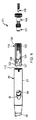
好ましい一実施形態では、本発明の装置61は、骨髄内ロッド62と、該ロッド62の近位側部分によりピボット回転可能に支持された近位側ファスナ63とを有している。近位側ファスナ63は、固定ねじ、ねじ、ペグ、ヘリカルブレードまたは他の任意の固定具を含む任意の適当な形式のものでよく、本明細書では簡単に固定ねじと呼ぶことにする。大腿爪すなわちロッド62は、長手方向軸線66に沿って延びる細長ボディ64を有し、該細長ボディ64は、近位側部分すなわちヘッド67と、中央部分すなわちネック68と、遠位側チップ71に終端する遠位側部分すなわちシャフト69とで構成される。細長ボディ64は、ロッド62が大腿内に挿入されたときに大腿の細い管の長さに沿ってロッド62を整合させるため、シャフトすなわちステム69の少なくとも一部を湾曲させることができる。細長ボディ64は、ステンレス鋼、チタンまたは他の合金等の任意の適当な材料から作ることができ、またロッド62が使用される長さに基いて180−500cmの範囲の長さにすることができる。爪62のヘッド67の長さは4−15cm、好ましくは8−12cm、直径は8−20mmにすることができる。
In a preferred embodiment, the
図3、図4および図9、図10に部分的に示すように、長手方向に延びる通路すなわちボア76がを設けることができる。該ボア76は、ヘッド67の近位側開口77からステムのチップの開口78まで延び、ロッドを大腿内に挿入するときにガイドワイヤに沿ってロッドをスライドできるようになっている。長手方向軸線66の湾曲したがってロッド62のステム69の湾曲は、単一平面を通る湾曲でも、多平面を通る湾曲でもよい。図8、図10、図12および図13に示すように、爪62の図示の実施形態では、ボディ64の湾曲は多平面を通って延びている。一実施形態では、ステム69のテーパ状チップ71に隣接するステム69の遠位端部分に、長手方向軸線66に垂直に延びる第1および第2ボア81が設けられている。ボアは、固定ねじ、ねじ、ペグ、ヘリカルブレードまたは他の任意の適当な固定具等のそれぞれの遠位側ファスナを受入れることができるサイズを有し、一実施形態では、このような遠位側ファスナは、ステム69に対して直角に固定される固定ねじまたはねじの形態をなしている。図示の実施形態では、図1、図2および図7−図9に示すように、最も遠位側のボア81は、ステム69の長手方向軸線66に平行な横断方向(transverse direction)に細長く、下に横たわる大腿の部分にファスナまたはねじを締付ける前に、それぞれの遠位側ファスナまたは固定ねじ82に対してステムを長手方向に移動させることができる。
A longitudinally extending passage or bore 76 can be provided, as shown in part in FIGS. 3, 4 and 9, 10. The
ロッド62のヘッド67を貫通して少なくとも1つの横断孔すなわち開口91が設けられており、該開口91は、一実施形態では長手方向軸線66に対してロッドの近位端の方向に傾斜して近位側固定ねじすなわち固定ねじ63を受入れることができる。より詳しくは、1つ以上の横断孔すなわち孔91の各々が固定ねじ63を受入れて、ねじ63と爪62との間の角度を変えることができる。このような孔すなわち第1孔の各々は、ロッドが大腿の細い管内に配置されるときに開口の軸線92が大腿のヘッドの方向を向くように、長手方向軸線66に対して傾斜した方向にヘッド67を通って延びるように形成される(図13参照)。図5、図6および図10−図13から明らかなように、ヘッド67の横断孔すなわち孔92は、それぞれ固定ねじが挿通される第1開口すなわち横方向横断開口(lateral transverse opening)93と、ねじの遠位側部分が突出する反対側の開口すなわち中間横断開口(medial transverse opening)94とに連通できる。図5、図8、図11および図13に示すように、中間横断開口94は、近位側固定ねじ63の遠位側部分がピボット回転できるように、横断方向に細長く、すなわちヘッド67およびボディ64の長手方向に平行に形成されている。
At least one transverse hole or
ロッド62のヘッド67には、横断孔91内で近位側固定ねじ63を選択的にピボット回転させる作動機構すなわち調節機構または組立体101を設けることができる(図4−図31参照)。この点を更に説明するならば、爪62の中央通路76の近位側部分は中空にして、ヘッドの近位側開口103に連通する長手方向に延びる近位側凹部102をヘッドに形成できる。図12および図13に示すように、凹部102は、近位側開口103に隣接する近位側部分102aと、セグメント化された円形部分102bとを有している。セグメント化された円形部分102bは、その断面で見て、中間横断開口94に隣接するヘッド67の内面に沿って任意の適当な角度(図12では約240°の角度が示されているが、好ましくは180−240°)に亘って延びている。近位側部分102aには、雌ねじ104を設けることができる。凹部102のセグメント化された円形部分すなわち
セグメント形部分102bは、内側弧状面105から形成できる。凹部102の他の側すなわちセグメント形部分102bとは反対側には、第1棚部107、第2棚部108および第3棚部109を形成できる。各棚部は、セグメント形部分102bの内側弧状面105よりも半径方向内方に位置し、長手方向軸線66に対して徐々に小さい半径を有する(図11−図13参照)。図4、図9および図10に示すように、任意であるが、第1棚部107の近位側部分には雌ねじ111を設けることができる。第1棚部107から第2棚部108へと半径方向内方に延びる肩部112を形成できる(図13参照)。図11に示すように、第3棚部は横方向横断開口93に当接できる。ヘッド67の近位端の近位側開口103には横断方向に整合したスロット110が設けられている。これらのスロット110は、目標骨内に爪62を配置するときまたは爪を操作するときに、爪62と、挿入ジグ標的器具または他の適当な器具とを整合させるためのものである。
The
近位側固定ねじ63をピボット回転させる作動機構101は任意の適当な形式のもので構成できるが、一実施形態では、作動機構101は、図5および図6の分解図および図4の組立て図に示すように、インサートすなわちスリーブ116と、スピンドル117と、端ナットすなわち安全ナット118と、整合ねじすなわち止めねじ119とからなる。これらのコンポーネンツの各々は、例えばステンレス鋼のような任意の適当な材料で作ることができる。
The
図14−図17に示すように、細長インサートすなわちスリーブ116は、近位側部分122と、遠位側部分123と、一側を貫通している長手方向開口124とを備えた管状部材121で形成できる。スリーブ116は円筒状の形状を有し、その一側に沿って設けられた細長切欠部126と、反対側の開口124とを備え、該開口124は、近位側端部すなわち頂端部128から遠位側端部すなわち底端部129まで貫通して延びる長手方向ボア127に連通している。平らな頂端部128および底端部129は互いに平行に形成できる。したがって、スリーブ116は、図16に示すように、その長手方向軸線に沿う端部から見たときにセグメント形円形すなわちC形の形状を有している。スリーブ116のこのような横断面形状は、ヘッド67のセグメント形円形部分102bの横断面形状に近似するのが好ましく、100−360°、好ましくは190−240°および図16に示すように約240°の弧状範囲に亘って形成できる。細長横断開口124はインサートの中央に形成できる。このような開口124は、爪62のヘッド67に設けられた中間横断開口94より小さい細長形状に形成できる。インサート116には、この近位側部分122に、ボア127を通って延びる雌ねじ131が設けられ、該雌ねじ131は、図14および図17に示すように、インサート116の頂端部すなわち近位側端部128に隣接している。インサート116は、30−110mmの長さおよび爪62のヘッド67内に嵌合できる外径サイズを有している。内部ボア127の遠位側部分すなわちボアの遠位側横断開口124の部分は、ボアの近位側部分の内径より小さい内径を有している。
As shown in FIGS. 14-17, the elongated insert or
スピンドル117は、一定半径の遠位側部分137が設けられた円筒状ボディ136から形成され、かつ滑らかな円筒状外面138と、遠位側部分137に隣接しかつ遠位側部分に対して半径方向外方に延びている雄ねじ141を備えた中央部分139と、該中央部分139に隣接する近位側部分すなわちネック部分142とを有している(図18−図22参照)。ネック部分142には、近位側フランジ143と、該フランジ143とスピンドル117の中央部分139との間に配置された環状凹部144とを設けることができる。図22に示すように、円筒状ボディ136には更に、近位側端部すなわち頂端部147と、遠位側端部すなわち底端部148とを設けることができる。スピンドル117を貫通する中央通路すなわちボア151を設けることができる。中央通路151の遠位側部分には雌ねじ152が設けられ、中央通路151の近位側部分には、駆動ソケット153として機能する任意の適当な横断面形状を形成できる。スピンドル117の長さは、5−50mmの範囲、好ましくは約15mmにすることができる。
The
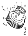
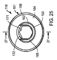
端ナット118は円筒状ボディ161から形成でき、ボディ161には、一定半径の滑らかな外面163を備えた遠位側部分162と、該遠位側部分162に隣接しかつ遠位側部分162に対して半径方向外方に延びている雄ねじ166を備えた近位側部分164とを有している(図23−図27参照)。図27に示すように、円筒状ボディ161には更に、近位側端部すなわち頂端部167と、遠位側端部すなわち底端部168とを設けることができる。平らな両端部167、158は互いに平行に形成できる。両端部167、168の間で端ナット118を長手方向に貫通して中央通路すなわち中央ボア171が延びており、ボア171の少なくとも近位側部分には、駆動ソケットとして機能する任意の適当な横断面形状を形成できる。端ナット118の遠位側端部168には凹部すなわちソケット172が設けられ、該ソケット172は、ボア171に連通しかつ遠位側部分162の円筒状外面163上に開口する側面を有している。ソケット172は、スピンドル117のネック部分142を協働的に受入れるサイズをもつように構成され、かつ図24に最も明瞭に示すように一部が環状でスピンドル117の環状凹部144内に一部が座合するように半径方向内方に延びたフランジ173と、スピンドル117の近位側環状フランジ143の一部を受入れるべく、フランジ173に対して半径方向外方に延びている一部が環状の凹部174とを有している。端ナット118の長さは、5−50mmの範囲内、好ましくは約15mmにすることができる。
The
止めねじ119は円筒状ボディ181から形成され、一定半径の滑らかな外面183を備えた遠位側部分182と、該遠位側部分182に隣接しかつこれに対して半径方向外方に延びている雄ねじ186を備えた近位側部分184とを有している(図28−図31)。図29に示すように、円筒状ボディ181には更に、近位側端部すなわち頂端部187と、遠位側端部すなわち底端部188とが設けられている。任意の適当な横断面形状を有する駆動ソケット191が、円筒状ボディ181の少なくとも一部に亘って長手方向に延びかつボディ181の頂端部187に開口している。ボディ181の底端部188は丸められている。止めねじ119の長さは、5−60mmの範囲内、好ましくは約20mmにすることができる。
The
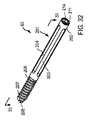
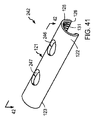
骨髄内ロッド62のヘッド67に使用する近位側ファスナ63は任意の適当な形式で作ることができ、一実施形態では、40−200mmの範囲内の長さおよび2−20mmの範囲内の直径を有する細長円筒状ボディ201またはスパイラルブレード(図示せず)から作られる(図32−図35参照)。図示の実施形態では、ファスナは、ねじ山付き部分および滑らかな部分を備えたボディから形成された固定ねじである。細長ボディ201はステンレス鋼のような任意の適当な材料から形成できかつ任意の外径または不規則形状の表面203を備えた近位側部分202を有している。近位側部分202には、軸線方向に延びる複数(図示の実施形態では4つ)のスロット204が設けられ、これらのスロット204は、周方向に間隔を隔てた位置で表面203の全体に配置されている。ボディ201の遠位側部分206には雄ねじ207が形成されており、該雄ねじ207は、ボディの尖鋭遠位端すなわちチップ208まで延びている。或いは、ボディ207の遠位側部分206は、不規則形状または平坦(図示せず)にすることもできる。ボディ201は更に近位端211を有し、かつボディを通って近位端211から遠位端208まで長手方向に延びている中央ボア212が設けられている。中央ボア212の近位端には雌ねじ213が設けられ、かつ該ねじ213を任意の適当な形式の駆動ツールに容易に連結できるようにする任意の適当な形式の駆動ソケット214が形成されている。
The
作動組立体すなわち作動機構101は、任意の適当な方法で爪62のヘッド67内に装着できる。一組立て方法では、インサートすなわちスリーブ116がヘッド67の近位側開口103を通してスライド可能に挿入されかつヘッド67内の凹部102のセグメント化された円形部分102b内にスライド可能に座合される。インサート116の横断開口124が、ヘッド67の中間横断開口94と全体的に整合される。スピンドル117の近位側部分142すなわちネック部分142が、端ナット118の遠位側部分162に形成されたソケット172内に座合され、これにより端ナット118とスピンドル117とがこれらの長手方向中心軸線に沿って同心状に配置される。スピンドル117とナット118との結合組立体は、スピンドルの遠位側部分137をヘッド67の近位側開口103内に導入することによりヘッド67内に装着される。中央ボア171の駆動ソケットを端ナットの近位側部分に係合させ、ヘッドの近位側開口103に隣接する雌ねじ104内で端ナットを回転させるのに適当な駆動ツール(図示せず)が使用され、これにより、端ナット118および該端ナットにより細くされたスピンドル117は、スピンドル117が、第1棚部107と第2棚部108との間で延びている肩部112に座合するまで、ヘッドの凹部102内で長手方向に移動される。スピンドル117がヘッド67の凹部102内で遠位側に移動されると、スピンドルの雄ねじ141が、インサート116の近位側部分122の雌ねじ131と係合する。スピンドル117は、この近位側部分すなわちネック部分142の駆動ソケット153と適当な駆動ツールとを係合させかつヘッド67の凹部102内でスピンドルを時計回り方向に回転させることにより、長手方向に移動されかつインサートとねじ係合される。
The actuation assembly or
次に、止めねじ119は、該止めねじの近位側端部184に設けられた雄ねじ186がスピンドルの遠位側部分137内に形成された雌ねじ152と係合するまで、端ナット118の中央ボア171を通してスピンドル117の中央ボア151内に導入される。適当な駆動ツールを用いて止めねじ119の近位側部分184の駆動ソケット191と係合させ、止めねじ119の雄ねじ186をスピンドルの雌ねじ152と回転係合させることにより止めねじをスピンドル117に対して遠位側に移動させる。これにより、止めねじの遠位側部分182はスピンドル117の遠位側に移動され、爪62のヘッド67の横断孔91内に入る。
Next, the
近位側固定ねじ63がヘッド67の横断孔91内に挿入されると、固定ねじ63は、インサート116の横断開口を通って、ヘッドの横断軸線の回りで、爪62に対して70°好ましくは約30°の角度に亘ってピボット回転できる。図示の一実施形態では、固定ねじ63は、爪のステム69に対して約115°の角度αで延びる第1位置216(図36)と、爪のステムに対して約145°の角度αで延びる第2位置(図37)との間でピボット回転できる。固定ねじは、爪のステムに対して約130°の角度αで延びる中間位置218(図36)にあるところが示されている。1つの手術で固定ねじをこのようにピボット回転させるには、医者は、例えばスピンドルのネック部分142内の駆動ソケット153と適当な駆動ツールとを係合させることにより、ヘッド67内でスピンドル117を回転させる。これにより、インサート116内の雌ねじ131と係合するスピンドルの中央部分139の雄ねじ141により、インサートが、ヘッド内で、セグメント化された円形部分内の第1位置すなわち遠位側位置(図示せず)から、セグメント化された円形部分内の第2位置すなわち近位側位置(図37)まで近位側に移動される。インサート116の横断開口124の遠位側端部は、ヘッド67内のインサートの近位側への移動中に固定ねじと係合して、該固定ねじを、ヘッドの横断孔91の横方向横断開口93内でピボット回転させる。スピンドル117は、図37に示すヘッド67内の作動位置にあるとき、ヘッドおよび端キャップ118に対して自由に回転できる。止めねじ119はスピンドル117により遠位側に回転され、これにより、止めねじの丸められた端部166が、固定ねじ63の近位側部分202に形成された長手方向スロットの1つ内に座合して、骨髄内ロッド62のヘッド67に対して固定ねじを回転可能にロックし、これにより、ねじ63がロッド62に対して更に好ましくなく前進することすなわち引出されることが防止される。
When the
爪62内に配置された長手方向に移動可能なインサートすなわちスリーブ116を備えた骨髄内ロッド62の作動機構101を示しかつ説明したが、爪62の外部にスライド可能に配置されたインサートすなわちスリーブを設けて、爪に対して固定ねじ62をピボット回転させることができる。
While the
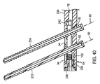
また、本発明の骨髄内ロッドの他の実施形態、例えばピボット回転可能な複数のファスナを備えた実施形態を提供できることは理解されよう。図38−図52には他の装置231が示されており、この装置231は、ロッド62と実質的に同じ骨髄内ロッド232を有している。ロッド62、232と同じコンポーネンツは、同じ参照番号を用いて説明する。骨髄内ロッド232は、第1および第2近位側固定ねじ233、234として示された任意の適当な第1および第2近位側ファスナを有し、これらの各ファスナは、横断孔91と実質的に同じでありかつそれぞれの軸線92に沿って延びている第1および第2横断孔236、237内にピボット回転可能に受入れられた近位側固定ねじ63と実質的に同じである。第1および第2ファスナ233、234は互いに平行に延びており、これらの長さおよび形式は同じでも、異なっていてもよい。例えば第1ファスナ233はねじとし、第2ファスナ234をペグまたはブレードとすることもできる。孔236、237は、ヘッド67と実質的に同様に、ロッド232のヘッド239に設けることができる。
It will also be appreciated that other embodiments of the intramedullary rod of the present invention can be provided, such as embodiments with multiple pivotable fasteners. 38-52 shows another
作動機構すなわち作動組立体241は、作動機構101と実質的に同様に、ロッド232のヘッド239に設けることができる。作動機構241(図40には、作動機構が組立てられた位置にあるところが示されている)はインサートすなわちスリーブ242を有している。このインサートすなわちスリーブ242は、機構101のインサート116と実質的に同じであるが、スリーブ116の横断孔91と同様な第1および第2横断孔246、247を備え、これらの横断孔246、247は、第1および第2固定ねじ233、234をそれぞれ受入れかつピボット回転させることができるように、爪の長手方向軸線に対して或る角度で延びている(図41−図44)。第1および第2横断孔246、247の軸線92は、互いに平行に形成することができるが、平行でなくてもよい。インサート242は、20−120mmの長さ、および爪232のヘッド239内に嵌合できるサイズの外径を有している。スピンドル256はスピンドル117と実質的に同様に形成できるが、スピンドル117の遠位側部分137は除去して形成できる(図45−図48参照)。その代わりに、図38−図52の二重固定ねじロッド232のスピンドル256は、スピンドル117の中央部分139と実質的に同様な近位側部分すなわちネック部分142および遠位側部分257を有している。スピンドル256は、5−30mmの範囲内の長さを有している。ナット118と実質的に同じであるが、長さの短い端キャップすなわち端ナット266を更に設けることができる(図49−図51参照)。端キャップ266は、3−30mmの範囲内の長さを有している。スピンドル256の近位側部分142は、図52では端ナット266の遠位側部分162のソケット172内に捕捉されすなわち座合しており、このため、スピンドルおよび端キャップが、互いにこれらの作動位置に同心状に整合しているところが示されている。
An actuation mechanism or actuation assembly 241 can be provided on the
作動組立体241のコンポーネンツは二重固定ねじロッド232のヘッド239内に装着され、装置61に関して上述したのと実質的に同じ方法で、第1および第2近位側固定ねじ233、234に対してヘッド239内で作動される。図40には、スリーブ242がその遠位側位置にあるところが示されている。装置241に第2固定ねじ234を設けることにより、止めねじ119のような止めねじの必要性を最小にでき、このような止めねじの必要性は無くすことが好ましい。この点について更に説明すると、第2近位側固定ねじは、ロッド232の使用中の第1近位側固定ねじ233に対する大腿骨頭の回転を防止すべく、ロッド232の手段すなわち機構内に設けられる。第1固定ねじに対する大腿骨頭の回転を防止するため、爪、ペグ、ブレードまたはボルト等の他の手段を本発明の骨髄内ロッド内に設けることは明らかである。任意であるが、第2孔237および第2近位側固定ねじ234がスライディング圧縮できるようにして、このような回転を防止しかつ装置または器具を種々の用途に適合させることができる。
The components of the actuating assembly 241 are mounted within the
本発明のピボット回転可能なファスナを備えた骨髄内ロッドの他の実施形態が図53に示されており、この実施形態では、装置61、231と実質的に同じ装置271が提供される。装置61、231、271の同じコンポーネンツは同じ参照番号を用いて説明する。装置271の骨髄内ロッドすなわち爪272はロッド62、232と実質的に同じであり、第1および第2近位側固定ねじ233、234として示された任意の適当な第1および第2近位側ファスナを有している。第1ねじ233は、軸線92に沿って延びている第1横断孔236内にピボット回転可能に受入れられる。第2ねじ234は、軸線274に沿って延びている第2横断孔273内にピボット回転可能に受入れられる。孔273は、第2横断孔273の軸線274が第1横断孔236の軸線92に対して平行でない点を除き、横断孔236と実質的に同じ構成にすることができる。第1および第2ファスナ233、234は互いに平行ではなく、また両ファスナの長さおよび形式は同じでも、異なるものでもよい。孔236、273は、ロッド232のヘッド239に実質的に同じであるロッド272のヘッド276内に設けられる。作動機構241と実質的に同じであるが、孔236、273の非平行位置を得るべく変更された作動機構すなわち組立体(図示せず)が提供される。
Another embodiment of an intramedullary rod with a pivotable fastener of the present invention is shown in FIG. 53, in which a
図54には、他の実施形態によるフォームまたは装置281が示されており、該装置281は、ロッド62、232と実質的に同じ骨髄内ロッド282を有している。ロッド62、232、282の同じコンポーネンツを説明するのに同じ参照番号が使用されている。骨髄内ロッド282は、第1、第2および第3近位側固定ねじ233、234、283として示されかつそれぞれ第1、第2および第3横断孔236、237、286内にピボット回転可能に受入れられた任意の適当な第1、第2および第3近位側ファスナを有している。第3近位側固定ねじ283は、第1および第2近位側固定ねじ233、234の一方または両方と同じに構成でき、第3横断孔286は第1および第2横断孔236、237の一方または両方と同じに構成できる。第1、第2および第3ファスナ233、234、283は互いに平行ではなく、また両ファスナの長さおよび形式は同じでも、異なるものでもよい。図示の実施形態では、ファスナ233、234、283は互いに平行に延びている。孔236、237、286は、ロッド232のヘッド239と実質的に同じロッド282のヘッド287内に形成される。作動機構241と実質的に同じであるが、第3横断孔286について変更されている作動機構すなわち組立体(図示せず)を設けることができる。
FIG. 54 shows a foam or device 281 according to another embodiment, which has an
図55および図56には、本発明のピボット回転可能なファスナを備えた骨髄内ロッドの更に別の実施形態が示されており、この実施形態では、装置61、231と実質的に同じ装置296が提供される。装置61、231、296と同じコンポーネンツは、同じ参照番号を用いて説明する。装置296の骨髄内ロッドすなわち爪297はロッド62、232と実質的に同じであり、第1および第2近位側固定ねじ233、234として示された任意の適当な第1および第2近位側ファスナを有している。第1ねじ233は、軸線92に沿って延びる第1横断孔236内にピボット回転可能に受入れられている。第2ねじ234は、軸線299に沿って延びる第2横断孔298内にピボット回転可能に受入れられている。第2横断孔298は、該横断孔298の軸線299が第1横断孔236の軸線92に対して平行でない点を除き、第1横断孔236と実質的に同じである。より詳しくは、軸線299は、図56に角度θで示すように、軸線92に対してロッド297の長手方向軸線66の回りで周方向に傾斜している。角度θは、任意の適当な数値である。軸線92、299は、図38に示すように、ロッド232の軸線92のような長手方向軸線66に対して同じ角度で延びるように構成するか、図53に示すように、ロッド272の軸線92、274のような長手方向軸線66に対して異なる角度で延びるように構成できる。第1および第2ファスナ233、234の長さおよび形式は、同じでもよいし、異ならせることもできる。孔236、298は、ロッド232のヘッド239と実質的に同じであるロッド297のヘッド301に設けられる。作動機構241と実質的に同じであるが、孔236、298の異なる周方向整合が得られるように変更された作動機構すなわち組立体(図示せず)が提供される。
55 and 56 illustrate yet another embodiment of an intramedullary rod with a pivotable fastener of the present invention, in which
本発明のピボット回転可能なファスナを備えた骨髄内ロッドの上記種々の実施形態から、このようなファスナの個数は任意の適当数に定めることができることは理解されよう。多数のファスナが設けられる場合には、ファスナは、互いに平行に配置するか、または長手方向軸線に対してまたは爪の長手方向軸線の回りで互いに種々の角度で配置することができる。図示の装置から、例えば、3つの非平行ファスナが設けられたもの、多数のファスナが、ロッドの長手方向軸線の回りで互いに周方向に整合しているが、ロッドの近位端から等距離の間隔を隔てて配置されたもの、または2つ以上第1ファスナがこのような長手方向軸線に対して周方向に整合しておりかつ1つ以上の第2ファスナが第1ファスナに対してこのような長手方向軸線の回りで周方向に間隔を隔てているものを推測できるであろう。 From the various embodiments of the intramedullary rod with pivotable fasteners of the present invention, it will be appreciated that the number of such fasteners can be any suitable number. Where multiple fasteners are provided, the fasteners can be arranged parallel to each other or at various angles with respect to the longitudinal axis or about the longitudinal axis of the nail. From the illustrated apparatus, for example, provided with three non-parallel fasteners, a number of fasteners are circumferentially aligned with each other about the longitudinal axis of the rod, but equidistant from the proximal end of the rod. Spatially spaced, or two or more first fasteners are circumferentially aligned with such a longitudinal axis and one or more second fasteners are thus relative to the first fastener. One could guess that there is a circumferential spacing around a long longitudinal axis.
本発明の装置は、各ファスナのロッドに別々の横断孔が設けられたものを図示したが、多数のファスナを、単一の孔にピボット回転可能に通すことを考えることもできる。単一の横断孔が2つのファスナを受入れる構成のこのような一実施形態では、ロッドの孔の1つまたは両方および作動機構の孔は、このような孔の2つの端部の間の幅が細くなっている構造を有し、このため、このような孔のそれぞれの端部を通って延びる2つのファスナは、ロッドおよび/または作動機構の細い材料により互いに分離される。 Although the device of the present invention is illustrated with a separate transverse hole in each fastener rod, it is also conceivable to pass a number of fasteners pivotably through a single hole. In such an embodiment in which a single transverse hole receives two fasteners, one or both of the rod holes and the hole of the actuation mechanism have a width between the two ends of such holes. The two fasteners having a narrowing structure and thus extending through the respective ends of such holes are separated from each other by the rod and / or the thin material of the actuation mechanism.
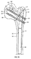
本発明のピボット回転可能な固定ねじを備えた骨髄内ロッドを用いる幾つかの手術方法が図57−図59に示されており、ここには、二重固定ねじロッド232を備えた装置231を用いて大腿311の転子周囲骨折を修復する方法が示されている。より詳しくは、図57−図59のそれぞれには、大腿骨頸骨折316の修復、転子間骨折317の修復および転子下骨折318の修復を行っているロッド232が示されている。本発明の手術方法の実施に先立ち、ロッド233が、大転子321を通して、大腿骨幹323の骨髄管322内に導入された。第1および第2固定ねじ233、234を、ロッドのヘッド239のそれぞれ第1および第2横断孔236、237の横方向横断開口93内に挿入できるようにするため、大転子の側部に適当な孔324が形成された。次に、固定ねじが大腿311の骨頭326内にねじ込まれた。しかしながら、各場合に、骨折が整復されないこと、大転子のロッドへの入口点が非常に横方向に位置すること、またはこれらを組合せた理由から、大腿骨頭の更なる調節が必要になることがある。本発明の一手術方法では、スピンドル256のネック部分142の駆動ソケット153内に座合させるため、適当な駆動要素(図示せず)が、大腿の入口点327を通して、爪232のヘッド239の近位側開口103内に導入される。スピンドル256は、駆動要素により例えば時計回り方向に回転され、これにより、スピンドルの雄ねじ141がインサートすなわちスリーブ242の近位側部分122の雌ねじと係合して、インサート242をヘッド239内で近位側にスライドすなわち移動させ、これにより、骨折が整復されかつ大腿311の骨頭326が図57−図59において仮想線で示すように内反され、したがって大腿の残部に対して適正に位置決めされるまで、第1および第2近位側固定ねじ233、234の各々を、ロッドのヘッド239に向けて上方(図57−図59で見て時計回り方向)にピボット回転させる。第1および第2近位側固定ねじは、これらのねじが、ロッド232のヘッド239に向かって上方にピボット回転される第2位置にあるときには図57−図59において参照番号233′、234′として示されている。
Several surgical methods using an intramedullary rod with a pivotable fixation screw of the present invention are shown in FIGS. 57-59, which include a
端ナット266のソケット172内のスピンドル256のネック部分142を捕捉することにより、スピンドル256がヘッド239の長手方向軸線と同心状位置から移動することが抑制され、これにより、ロッドのヘッド239内でのスピンドル256のこのような不整合から生じるインサート242の好ましくない移動、およびインサートにより所定位置に保持された第1および第2固定ねじ233、234の好ましくない移動が抑制される。第2固定ねじ234は、第1固定ねじ233に対する大腿骨頭326の回転を防止できないまでも抑制する。
Capturing the
本発明の装置には、大腿骨頭326または他の任意の適当な骨の一部を固定するのに2つ以上の近位側ファスナを設けることができ、これも本発明の範囲内にある。
上記説明から理解されようが、骨髄内爪の固定特性とスライド圧縮ねじの利益とを結合した、大腿骨折を治療する装置が提供される。本発明の装置は、これまで2つ以上の器具を必要とした種々の大腿骨折を治療する単一器具を提供する。この器具は、種々の大腿骨折および大腿骨切り部の治療に使用でき、かつ病院および製造業者が整形外科器具の種々の在庫を低減することを可能にし、したがってコストを低減させることを可能にする。本発明の器具は、医者が、移植後に骨折または骨切り部をより好ましい位置に移動させることを可能にし、例えば、大腿骨頸または転子間骨折部のスライド圧縮することを可能にする。本発明の装置は、医者が、大腿骨頭内に延びる近位側固定ねじの角度を変えることを可能にし、これは、大腿骨髄内管内への大腿ロッドの挿入の前または後に行うことができる。
The device of the present invention may be provided with more than one proximal fastener to secure the
As will be appreciated from the above description, an apparatus for treating a femoral fracture is provided that combines the fixation characteristics of an intramedullary nail and the benefits of a slide compression screw. The device of the present invention provides a single instrument for treating various femoral fractures that previously required more than one instrument. This instrument can be used to treat various femoral fractures and cuts, and allows hospitals and manufacturers to reduce various stocks of orthopedic instruments, thus reducing costs. . The device of the present invention allows the physician to move the fracture or osteotomy to a more favorable position after implantation, for example, to slide compress the femoral neck or intertrochanteric fracture. The device of the present invention allows the physician to change the angle of the proximal fixation screw that extends into the femoral head, which can be done before or after insertion of the femoral rod into the femoral intramedullary canal.
62 骨髄内ロッド(大腿爪、爪)
63 近位側ファスナ
64 細長ボディ
67 近位側部分(ヘッド)
68 中央部分(ネック)
69 遠位側部分(シャフト、ステム)
82 ねじ
101 作動機構
116 インサート(スリーブ)
117 スピンドル
118 端ナット(安全ナット)
119 整合ねじ(止めねじ)
62 Bone marrow rod (thigh nails, nails)
63
68 Center part (neck)
69 Distal part (shaft, stem)
82
117
119 Alignment screw (set screw)
Claims (7)
中央長手方向軸線(66)に沿って延びかつステム(69)およびヘッド(67)を備えた細長爪(62)を有し、該ヘッドには、前記中央長手方向軸線に対して傾斜して延びておりかつファスナを受入れることができる孔(91,236)が設けられ、
該孔(91,236)は、前記中央長手方向軸線から間隔をおいた第1及び第2の側部分及び前記ファスナを前記第1側部分に係合させるためのヘッドによって支持された長手方向へ移動可能なインサート(116)を有し、前記ファスナを、前記ヘッドに対する第1傾斜位置から前記ヘッドに対する第2傾斜位置まで前記中央長手方向軸線から間隔を置いた横断軸線の回りで適所にピボット回転させることを特徴とする骨髄内ロッド。 In an intramedullary rod for use in fasteners (63,233) to repair bones in the mammalian body,
Extending along a central longitudinal axis (66) and having an elongated claw (62) with a stem (69) and a head (67), the head extends at an angle to the central longitudinal axis. And holes (91, 236) are provided for receiving fasteners,
The holes (91,236) is the first and second side portions and a longitudinal direction and is supported by a head for engaging the fastener to the first portion spaced from the central longitudinal axis Having a movable insert (116) and pivoting the fastener in place about a transverse axis spaced from the central longitudinal axis from a first inclined position relative to the head to a second inclined position relative to the head; An intramedullary rod characterized in that
Applications Claiming Priority (3)
| Application Number | Priority Date | Filing Date | Title |
|---|---|---|---|
| US93688707P | 2007-06-22 | 2007-06-22 | |
| US60/936,887 | 2007-06-22 | ||
| PCT/US2008/067818 WO2009002890A1 (en) | 2007-06-22 | 2008-06-22 | Intramedullary rod with pivotable fastener and method for using same |
Publications (3)
| Publication Number | Publication Date |
|---|---|
| JP2010530791A JP2010530791A (en) | 2010-09-16 |
| JP2010530791A5 JP2010530791A5 (en) | 2011-08-11 |
| JP5566287B2 true JP5566287B2 (en) | 2014-08-06 |
Family
ID=40186001
Family Applications (1)
| Application Number | Title | Priority Date | Filing Date |
|---|---|---|---|
| JP2010513479A Expired - Fee Related JP5566287B2 (en) | 2007-06-22 | 2008-06-22 | Bone marrow rod with pivotable fastener and method of use |
Country Status (10)
| Country | Link |
|---|---|
| US (4) | US8906023B2 (en) |
| EP (2) | EP3153119B1 (en) |
| JP (1) | JP5566287B2 (en) |
| KR (1) | KR101503665B1 (en) |
| CN (1) | CN101754723B (en) |
| AU (1) | AU2008268507C1 (en) |
| BR (1) | BRPI0813156A2 (en) |
| CA (1) | CA2690786C (en) |
| ES (1) | ES2595308T3 (en) |
| WO (1) | WO2009002890A1 (en) |
Families Citing this family (62)
| Publication number | Priority date | Publication date | Assignee | Title |
|---|---|---|---|---|
| US9320551B2 (en) | 2007-01-26 | 2016-04-26 | Biomet Manufacturing, Llc | Lockable intramedullary fixation device |
| US9308031B2 (en) | 2007-01-26 | 2016-04-12 | Biomet Manufacturing, Llc | Lockable intramedullary fixation device |
| US8157802B2 (en) * | 2007-01-26 | 2012-04-17 | Ebi, Llc | Intramedullary implant with locking and compression devices |
| US8303590B2 (en) * | 2007-01-26 | 2012-11-06 | Ebi, Llc | Lockable intramedullary fixation device |
| EP3153119B1 (en) | 2007-06-22 | 2020-05-06 | Epix Orthopaedics, Inc. | Intramedullary rod with mechanism actuatable at proximal end for pivoting fastener |
| CN101827560A (en) | 2007-10-16 | 2010-09-08 | Ebi有限责任公司 | Method and apparatus for orthopedic fixation |
| US9044282B2 (en) * | 2008-06-24 | 2015-06-02 | Extremity Medical Llc | Intraosseous intramedullary fixation assembly and method of use |
| US8313487B2 (en) * | 2008-06-24 | 2012-11-20 | Extremity Medical Llc | Fixation system, an intramedullary fixation assembly and method of use |
| US20110230884A1 (en) * | 2008-06-24 | 2011-09-22 | Adam Mantzaris | Hybrid intramedullary fixation assembly and method of use |
| US8303589B2 (en) | 2008-06-24 | 2012-11-06 | Extremity Medical Llc | Fixation system, an intramedullary fixation assembly and method of use |
| US8343199B2 (en) * | 2008-06-24 | 2013-01-01 | Extremity Medical, Llc | Intramedullary fixation screw, a fixation system, and method of fixation of the subtalar joint |
| US8328806B2 (en) | 2008-06-24 | 2012-12-11 | Extremity Medical, Llc | Fixation system, an intramedullary fixation assembly and method of use |
| US9017329B2 (en) * | 2008-06-24 | 2015-04-28 | Extremity Medical, Llc | Intramedullary fixation assembly and method of use |
| US9289220B2 (en) * | 2008-06-24 | 2016-03-22 | Extremity Medical Llc | Intramedullary fixation assembly and method of use |
| WO2010042767A1 (en) * | 2008-10-11 | 2010-04-15 | Anthem Orthopaedics Van, Llc | Intramedullary rod with pivotable and fixed fasteners and method for using same |
| CN102176873A (en) * | 2008-10-15 | 2011-09-07 | 捷迈有限公司 | Intramedullary nail |
| EP3042621B1 (en) | 2009-01-16 | 2017-08-09 | Carbofix Orthopedics Ltd. | Composite material bone implant |
| US9295504B2 (en) * | 2009-03-31 | 2016-03-29 | Biomet C.V. | Intramedullary nail with locking key |
| WO2011018778A1 (en) * | 2009-08-13 | 2011-02-17 | Cork Institute Of Technology | Intramedullary nails for long bone fracture setting |
| EP2575656B1 (en) | 2010-06-07 | 2019-04-10 | Carbofix Orthopedics Ltd. | Composite material bone implant |
| US10154867B2 (en) | 2010-06-07 | 2018-12-18 | Carbofix In Orthopedics Llc | Multi-layer composite material bone screw |
| HUE026086T2 (en) | 2010-07-09 | 2016-05-30 | Synthes Gmbh | Intramedullary nail |
| FR2965471B1 (en) * | 2010-09-30 | 2013-07-26 | Christian Cuny | INTRAMEDULAR FASTENING ASSEMBLY |
| ES2551874T3 (en) | 2011-02-08 | 2015-11-24 | Stryker Trauma Gmbh | Bone fixation implant system |
| CA2826703C (en) * | 2011-02-14 | 2019-06-25 | DePuy Synthes Products, LLC | Intramedullary nail having self-retaining compression slot |
| TWI434667B (en) * | 2011-03-30 | 2014-04-21 | Metal Ind Res & Dev Ct | Medical instrument with three dimensional fixation shape memory intramedullary nail |
| US9220544B2 (en) * | 2011-12-15 | 2015-12-29 | Epix Orthopaedics, Inc. | Implantable device with locking adjustment mechanism and method for using same |
| US9526549B2 (en) | 2012-01-16 | 2016-12-27 | Carbofix Orthopedics Ltd. | Bone screw with insert |
| CN107184248B (en) * | 2012-02-08 | 2020-02-21 | Epix整形外科股份有限公司 | Implant insertion device |
| CN104411259B (en) * | 2012-02-08 | 2017-06-13 | Epix整形外科股份有限公司 | The implant insertion apparatus of the aiming component with continuously adjustable |
| US9017055B2 (en) * | 2012-07-12 | 2015-04-28 | Biomet Manufacturing, Llc | Device for coating intramedullary rods with cement |
| EP2916742B1 (en) | 2012-11-12 | 2018-08-29 | Ziran, Navid | Dynamic axial nail for intramedullary treatment of long bone fractures |
| US10123828B2 (en) * | 2013-03-15 | 2018-11-13 | Epix Orthopaedics, Inc. | Implantable device with pivotable fastener and self-adjusting set screw |
| US9468478B2 (en) | 2013-07-24 | 2016-10-18 | Sreevathsa Boraiah | Interlocking intramedullary rod assembly for proximal femoral fractures, including unstable hip fractures |
| US9757169B2 (en) * | 2013-07-24 | 2017-09-12 | Sreevathsa Boraiah | Interlocking intramedullary rod assembly for proximal femoral fractures, including unstable hip fractures |
| US9433451B2 (en) | 2013-12-09 | 2016-09-06 | Acumed Llc | Hip fixation system with a compliant fixation element |
| US10080596B2 (en) | 2013-12-09 | 2018-09-25 | Acumed Llc | Hip fixation with load-controlled dynamization |
| US9526542B2 (en) * | 2014-05-07 | 2016-12-27 | Acumed Llc | Hip fixation with load-controlled dynamization |
| EP3756596A1 (en) | 2013-12-09 | 2020-12-30 | Acumed LLC | Nail-based compliant hip fixation system |
| US9463055B2 (en) | 2013-12-09 | 2016-10-11 | Acumed Llc | Plate-based compliant hip fixation system |
| JP6562596B2 (en) * | 2014-05-21 | 2019-08-21 | ディトマール・ヴォルター | Osteosynthesis system for multi-directional, angle-stable treatment of tubular fractures with intramedullary nails and bone screws |
| JP6562595B2 (en) * | 2014-05-21 | 2019-08-21 | ディトマール・ヴォルター | Osteosynthesis system for multi-directional, angle-stable treatment of tubular fractures with intramedullary nails and bone screws |
| ES2737225T3 (en) | 2015-05-22 | 2020-01-10 | Stryker European Holdings I Llc | Bone fixation implant system |
| US10617458B2 (en) | 2015-12-23 | 2020-04-14 | Carbofix In Orthopedics Llc | Multi-layer composite material bone screw |
| UY37137A (en) | 2016-02-24 | 2017-09-29 | Merial Inc | ANTIPARASITARY COMPOUNDS OF ISOXAZOLINE, INJECTABLE FORMULATIONS OF PROLONGED ACTION THAT INCLUDE THEM, METHODS AND USES OF THE SAME |
| US10219846B2 (en) * | 2016-03-04 | 2019-03-05 | Nail Kinetics, LLC | Interlocking intramedullary rod assembly for treating proximal tibial fractures |
| WO2018042595A1 (en) * | 2016-09-01 | 2018-03-08 | 株式会社オーミック | Thighbone fixing tool |
| US10492803B2 (en) | 2016-09-22 | 2019-12-03 | Globus Medical, Inc. | Systems and methods for intramedullary nail implantation |
| US10299847B2 (en) * | 2016-09-22 | 2019-05-28 | Globus Medical, Inc. | Systems and methods for intramedullary nail implantation |
| US11083503B2 (en) | 2016-09-22 | 2021-08-10 | Globus Medical, Inc. | Systems and methods for intramedullary nail implantation |
| US11471201B2 (en) * | 2016-10-10 | 2022-10-18 | Francisco FERRERO MANZANAL | Cephalomedullary nailing system of variable angle to treat femur fractures and the utensils used to place the system |
| US10716682B2 (en) | 2017-07-19 | 2020-07-21 | Acumed Llc | Orthopedic alignment guide |
| US10952774B2 (en) * | 2017-08-07 | 2021-03-23 | The Solsidan Group, LLC | Orthopaedic fixation assembly, system, and method of use |
| EP3466357B1 (en) * | 2017-10-09 | 2022-01-05 | Globus Medical, Inc. | Systems intramedullary nail implantation |
| US11446072B2 (en) | 2017-10-10 | 2022-09-20 | DePuy Synthes Products, Inc. | Self-retaining nail to insertion handle interface |
| US10932828B2 (en) * | 2018-01-25 | 2021-03-02 | Advanced Orthopaedic Solutions, Inc. | Bone nail |
| CN109394325A (en) * | 2018-10-26 | 2019-03-01 | 大博医疗科技股份有限公司 | A kind of adjustable intramedullary nail and medical embedded fixed system |
| US10856916B2 (en) * | 2018-11-15 | 2020-12-08 | DePuy Synthes Products, Inc. | Flexible shaft guide tube |
| US11633219B2 (en) | 2019-06-26 | 2023-04-25 | Globus Medical, Inc. | Fenestrated pedicle nail |
| CN110811802B (en) * | 2019-09-11 | 2020-11-20 | 杭州辰昀企业管理有限公司 | Reduction support assembly for treating femoral fracture |
| US11857228B2 (en) | 2020-03-06 | 2024-01-02 | Stryker European Operations Limited | Set screw for femoral nail |
| WO2021240242A1 (en) | 2020-05-29 | 2021-12-02 | Stryker European Operations Limited | Funnel hole for intramedullary nail |
Family Cites Families (109)
| Publication number | Priority date | Publication date | Assignee | Title |
|---|---|---|---|---|
| US2181746A (en) | 1939-02-04 | 1939-11-28 | John R Siebrandt | Combination bone clamp and adjustable drill guide |
| US2441765A (en) * | 1945-04-28 | 1948-05-18 | Surgical Specialties Corp | Surgical device |
| US3308812A (en) * | 1964-05-27 | 1967-03-14 | Gidlund Ake Samuel | Device for osteosynthesis |
| US3783860A (en) * | 1972-10-27 | 1974-01-08 | Sampson Corp | Intramedullary rod |
| US4519100A (en) * | 1982-09-30 | 1985-05-28 | Orthopedic Equipment Co. Inc. | Distal locking intramedullary nail |
| US4657001A (en) * | 1984-07-25 | 1987-04-14 | Fixel Irving E | Antirotational hip screw |
| CH666176A5 (en) | 1984-11-30 | 1988-07-15 | Straumann Inst Ag | DEVICE FOR TREATING A BONE AND NAIL FOR SUCH A DEVICE. |
| US4622959A (en) * | 1985-03-05 | 1986-11-18 | Marcus Randall E | Multi-use femoral intramedullary nail |
| US4653487A (en) * | 1986-01-29 | 1987-03-31 | Maale Gerhard E | Intramedullary rod assembly for cement injection system |
| US4733654A (en) * | 1986-05-29 | 1988-03-29 | Marino James F | Intramedullar nailing assembly |
| US5190544A (en) * | 1986-06-23 | 1993-03-02 | Pfizer Hospital Products Group, Inc. | Modular femoral fixation system |
| US4776330A (en) * | 1986-06-23 | 1988-10-11 | Pfizer Hospital Products Group, Inc. | Modular femoral fixation system |
| US5167663A (en) * | 1986-12-30 | 1992-12-01 | Smith & Nephew Richards Inc. | Femoral fracture device |
| US4827917A (en) * | 1986-12-30 | 1989-05-09 | Richards Medical Company | Fermoral fracture device |
| US4846162A (en) * | 1987-09-14 | 1989-07-11 | Moehring H David | Orthopedic nail and method of bone fracture fixation |
| US5176681A (en) * | 1987-12-14 | 1993-01-05 | Howmedica International Inc. | Intramedullary intertrochanteric fracture fixation appliance and fitting device |
| US4881535A (en) * | 1988-09-06 | 1989-11-21 | Sohngen Gary W | Intramedullary rod targeting device |
| US5032125A (en) * | 1990-02-06 | 1991-07-16 | Smith & Nephew Richards Inc. | Intramedullary hip screw |
| US5047034A (en) * | 1990-05-29 | 1991-09-10 | Ace Orthopedic Manufacturing | Intramedullary rod screw guide |
| US5248313A (en) * | 1991-04-17 | 1993-09-28 | Greene Bruce L | Fibular intramedullary rod |
| US5127913A (en) * | 1991-04-22 | 1992-07-07 | Thomas Jr Charles B | Apparatus and method for implanting an intramedullary rod |
| CH685851A5 (en) | 1991-05-24 | 1995-10-31 | Synthes Ag | A surgical instrument for positioning osteosynthetic fasteners |
| GB9113578D0 (en) * | 1991-06-24 | 1991-08-14 | Howmedica | Intramedullary intertrochanteric fracture fixation appliance |
| US5429640A (en) * | 1992-11-27 | 1995-07-04 | Clemson University | Intramedullary rod for fracture fixation of femoral shaft independent of ipsilateral femoral neck fracture fixation |
| US5514137A (en) * | 1993-12-06 | 1996-05-07 | Coutts; Richard D. | Fixation of orthopedic devices |
| DE9412873U1 (en) | 1994-08-10 | 1994-10-13 | Howmedica Gmbh | Device for stabilizing long bones, especially for osteotomy |
| US5545813A (en) * | 1995-01-31 | 1996-08-13 | Pioneer Hi-Bred International, Inc. | Inbred maize line PHRF5 |
| US5776194A (en) | 1996-04-25 | 1998-07-07 | Nuvana Medical Innovations, Llc | Intermedullary rod apparatus and methods of repairing proximal humerus fractures |
| DE29620327U1 (en) | 1996-11-22 | 1998-03-26 | Howmedica Gmbh | Locking nail with adjustable openings for locking screws |
| IT1293934B1 (en) * | 1997-01-21 | 1999-03-11 | Orthofix Srl | ENDOMIDOLLAR NAIL FOR THE TREATMENT OF HIP FRACTURES |
| EP1342453B1 (en) * | 1997-03-19 | 2005-08-24 | Stryker Trauma GmbH | Modular intramedullary nail |
| US6985207B2 (en) * | 1997-07-15 | 2006-01-10 | Silverbrook Research Pty Ltd | Photographic prints having magnetically recordable media |
| US5935127A (en) * | 1997-12-17 | 1999-08-10 | Biomet, Inc. | Apparatus and method for treatment of a fracture in a long bone |
| US6129729A (en) * | 1998-11-11 | 2000-10-10 | Snyder; Samuel J. | Apparatus and method for targeting and/or installing fasteners into an intramedullary nail |
| US6120504A (en) * | 1998-12-10 | 2000-09-19 | Biomet Inc. | Intramedullary nail having dual distal bore formation |
| US6123708A (en) * | 1999-02-03 | 2000-09-26 | Pioneer Laboratories, Inc. | Intramedullary bone fixation rod |
| US6783529B2 (en) * | 1999-04-09 | 2004-08-31 | Depuy Orthopaedics, Inc. | Non-metal inserts for bone support assembly |
| US7008425B2 (en) * | 1999-05-27 | 2006-03-07 | Jonathan Phillips | Pediatric intramedullary nail and method |
| US7018380B2 (en) * | 1999-06-10 | 2006-03-28 | Cole J Dean | Femoral intramedullary rod system |
| US6221074B1 (en) * | 1999-06-10 | 2001-04-24 | Orthodyne, Inc. | Femoral intramedullary rod system |
| DE59911776D1 (en) * | 1999-07-07 | 2005-04-21 | Synthes Ag | ANGLE ADJUSTABLE BONE SCREW AND DEVICE FOR OSTEOSYNTHETIC BONE FIXATION |
| US6926719B2 (en) * | 1999-10-21 | 2005-08-09 | Gary W. Sohngen | Modular intramedullary nail |
| AU2001231272A1 (en) * | 2000-02-02 | 2001-08-14 | Owen A. Nelson | An orthopedic implant used to repair intertrochanteric fractures and a method for inserting the same |
| US6235031B1 (en) * | 2000-02-04 | 2001-05-22 | Encore Medical Corporation | Intramedullary fracture fixation device |
| JP4278289B2 (en) * | 2000-07-27 | 2009-06-10 | 有限会社ケイオーアイ | Intramedullary nail |
| US6648889B2 (en) * | 2001-04-24 | 2003-11-18 | Dale G. Bramlet | Intramedullary hip nail with bifurcated lock |
| US6443954B1 (en) * | 2001-04-24 | 2002-09-03 | Dale G. Bramlet | Femoral nail intramedullary system |
| US6488684B2 (en) * | 2001-04-25 | 2002-12-03 | Dale G. Bramlet | Intramedullary nail |
| EP1260188B1 (en) * | 2001-05-25 | 2014-09-17 | Zimmer GmbH | Femoral bone nail for implantation in the knee |
| US6860691B2 (en) * | 2001-06-18 | 2005-03-01 | John Duncan Unsworth | Self adjusting, high strength, screw system |
| DE10164464A1 (en) | 2001-12-20 | 2003-07-03 | Merete Medical Gmbh | Modular bone nail |
| GB2387112A (en) | 2002-02-23 | 2003-10-08 | Odathurai Nallasam Paramasivan | Bone fracture compression assembly |
| ITBO20020200A1 (en) | 2002-04-15 | 2003-10-15 | Hit Medica Srl | DEVICE FOR THE POSITIONING OF A SCREW TO BE ASSOCIATED AND AN ENDOMIDULAR NAIL FIXED IN THE FEMORE MEDILLARY CHANNEL |
| US7780710B2 (en) * | 2004-01-23 | 2010-08-24 | Depuy Products, Inc. | System for stabilization of fractures of convex articular bone surfaces including subchondral support structure |
| US7001386B2 (en) * | 2002-07-23 | 2006-02-21 | Advanced Orthopaedic Solutions, Inc. | Intramedullary nail for long bone fractures |
| WO2004096067A2 (en) | 2003-04-29 | 2004-11-11 | Grampian University Hospitals Nhs Trust | Bone fixture apparatus |
| ATE533419T1 (en) * | 2003-05-17 | 2011-12-15 | Depuy Int Ltd | INTEGRAL NAIL SYSTEM |
| US7951176B2 (en) * | 2003-05-30 | 2011-05-31 | Synthes Usa, Llc | Bone plate |
| US20050055024A1 (en) * | 2003-09-08 | 2005-03-10 | James Anthony H. | Orthopaedic implant and screw assembly |
| US7799030B2 (en) * | 2003-09-08 | 2010-09-21 | Smith & Nephew, Inc. | Orthopaedic plate and screw assembly |
| US7267678B2 (en) * | 2003-09-30 | 2007-09-11 | Robert J. Medoff | Intramedullary implant for fracture fixation |
| US7699879B2 (en) * | 2003-10-21 | 2010-04-20 | Warsaw Orthopedic, Inc. | Apparatus and method for providing dynamizable translations to orthopedic implants |
| US6925719B2 (en) * | 2003-12-01 | 2005-08-09 | Lars Callne | Powered coping saw |
| US7601153B2 (en) * | 2003-12-25 | 2009-10-13 | Homs Engineering Inc. | Intramedullary nail |
| US7947043B2 (en) | 2004-01-20 | 2011-05-24 | Depuy Products, Inc. | Intramedullary nail and associated method |
| ES2400720T3 (en) * | 2004-01-23 | 2013-04-11 | Depuy Products, Inc. | System for stabilizing fractures of convex joint bone surfaces that include subcartilaginous support structures |
| WO2005079676A1 (en) * | 2004-02-23 | 2005-09-01 | Synthes Ag Chur | Intramedullary nail |
| WO2005092219A1 (en) | 2004-03-26 | 2005-10-06 | Hirotaka Shimizu | Bone connecting tool |
| WO2005094707A2 (en) | 2004-03-26 | 2005-10-13 | Smith & Nephew, Inc. | Methods for treating fractures of the femur and femoral fracture devices |
| JP3609825B1 (en) | 2004-03-26 | 2005-01-12 | 弘毅 清水 | Osteosynthesis device |
| US7771428B2 (en) * | 2004-06-11 | 2010-08-10 | Synthes Usa, Llc | Intramedullary rod with spiraling flutes |
| US20060015101A1 (en) * | 2004-07-15 | 2006-01-19 | Wright Medical Technology, Inc. | Intramedullary fixation assembly and devices and methods for installing the same |
| US7918896B2 (en) * | 2004-09-15 | 2011-04-05 | Wright Medical Technology, Inc. | Unitary acetabular cup prosthesis with extension for deficient acetabulum |
| ATE395871T1 (en) * | 2004-09-27 | 2008-06-15 | Orthofix Srl | INTEGRAL NAIL FOR THE TREATMENT OF PROXIMAL FEMUR Fractures |
| US7621916B2 (en) * | 2004-11-18 | 2009-11-24 | Depuy Spine, Inc. | Cervical bone preparation tool and implant guide systems |
| JP4289342B2 (en) * | 2004-11-22 | 2009-07-01 | 日本ビクター株式会社 | Optical disc and manufacturing method thereof |
| WO2006066440A2 (en) | 2004-12-23 | 2006-06-29 | Staeubli Hans Ulrich | Bone fixing device |
| EP1850763B1 (en) | 2005-02-22 | 2016-09-07 | Smith & Nephew, Inc. | Instrument for targeting blocking screws |
| SG157353A1 (en) | 2005-04-05 | 2009-12-29 | Orthopaedic Int Inc | Intramedullary nail distal targeting device |
| US20070049939A1 (en) * | 2005-08-31 | 2007-03-01 | Wallace Matthew S | Intramedullary nail assembly with sleeve and screw for use therewith |
| US20070049940A1 (en) * | 2005-08-31 | 2007-03-01 | Wallace Matthew S | Intramedullary nail assembly with fixed securement and associated method |
| US20070049938A1 (en) * | 2005-08-31 | 2007-03-01 | Wallace Matthew S | Intramedullary nail assembly with locking component, locking component and nail for use therewith |
| AU2006304847B2 (en) * | 2005-10-21 | 2011-09-15 | Acumed Llc | Orthopedic rod with locking aperture |
| CN101296663B (en) * | 2005-10-25 | 2011-05-25 | 圣歌整形外科有限责任公司 | Bone fastening assembly and bushing and screw for use therewith |
| US20070123876A1 (en) | 2005-10-31 | 2007-05-31 | Czartoski Timothy J | Multiple purpose nail, nail assembly and associated method |
| US20070123873A1 (en) * | 2005-10-31 | 2007-05-31 | Czartoski Timothy J | Intramedullary nail with oblique openings |
| JP4224053B2 (en) * | 2005-11-29 | 2009-02-12 | 哲雄 中野 | Fracture adjustment joint |
| JP2009524494A (en) * | 2006-01-27 | 2009-07-02 | スミス アンド ネフュー インコーポレーテッド | Fracture reduction assembly |
| US11049117B2 (en) * | 2006-02-02 | 2021-06-29 | Verizon Media Inc. | Syndicated ratings and reviews |
| US7967820B2 (en) * | 2006-02-07 | 2011-06-28 | P Tech, Llc. | Methods and devices for trauma welding |
| US20070233102A1 (en) * | 2006-03-31 | 2007-10-04 | Metzinger Anthony J | Variable angle fixture, kit and method of presetting a nail assembly |
| US20070233101A1 (en) * | 2006-03-31 | 2007-10-04 | Metzinger Anthony J | Variable angle intramedullary nail, assembly and method |
| US20070233100A1 (en) * | 2006-03-31 | 2007-10-04 | Metzinger Anthony J | Variable angle intramedullary nail |
| US20070270846A1 (en) * | 2006-03-31 | 2007-11-22 | Metzinger Anthony J | Fixture, intramedullary nail kit and method of presetting a nail assembly |
| US20070233104A1 (en) * | 2006-03-31 | 2007-10-04 | Metzinger Anthony J | Intramedullary nail implant assembly, kit and method |
| AU2007323566A1 (en) * | 2006-11-22 | 2008-05-29 | Sonoma Orthopedic Products, Inc. | Fracture fixation device, tools and methods |
| US20080140077A1 (en) * | 2006-12-09 | 2008-06-12 | Adel Kebaish | Femoral Universal Nail |
| US20080147066A1 (en) * | 2006-12-19 | 2008-06-19 | Zimmer Technology, Inc. | Bone fixing system |
| US8961568B2 (en) | 2007-01-12 | 2015-02-24 | Lanx, Inc. | Bone fastener assembly |
| US20080287949A1 (en) * | 2007-05-15 | 2008-11-20 | Zimmer, Inc. | Method and apparatus for securing a bone screw to an intramedullary nail |
| DE102007051136A1 (en) | 2007-05-23 | 2009-04-30 | Eichhorn, Stefan, Dipl.-Ing. | Lockable intramedullary nail and fixation device |
| ITUD20070099A1 (en) | 2007-05-31 | 2008-12-01 | Enzo Scaglia | SURGICAL DEVICE |
| EP3153119B1 (en) | 2007-06-22 | 2020-05-06 | Epix Orthopaedics, Inc. | Intramedullary rod with mechanism actuatable at proximal end for pivoting fastener |
| US8641740B2 (en) * | 2007-09-26 | 2014-02-04 | Zimmer, Gmbh | Bone anchoring device for the operative repair of fractures |
| US8100911B2 (en) * | 2008-06-30 | 2012-01-24 | Depuy Products, Inc. | Fracture fixation apparatus |
| WO2010042767A1 (en) | 2008-10-11 | 2010-04-15 | Anthem Orthopaedics Van, Llc | Intramedullary rod with pivotable and fixed fasteners and method for using same |
| WO2010091242A1 (en) * | 2009-02-05 | 2010-08-12 | Novalign Orthopaedics, Inc. | Proximal femur fixation apparatus, systems and methods with angled elongate elements |
| US8926611B2 (en) * | 2009-09-14 | 2015-01-06 | Zimmer Gmbh | Angular lag implant for intramedullary nails |
| CN103189006B (en) * | 2010-10-27 | 2016-09-21 | 新特斯有限责任公司 | Bone implantation piece |
-
2008
- 2008-06-22 EP EP16189449.8A patent/EP3153119B1/en active Active
- 2008-06-22 CA CA2690786A patent/CA2690786C/en active Active
- 2008-06-22 EP EP08780913.3A patent/EP2166970B1/en active Active
- 2008-06-22 US US12/143,798 patent/US8906023B2/en active Active
- 2008-06-22 WO PCT/US2008/067818 patent/WO2009002890A1/en active Application Filing
- 2008-06-22 BR BRPI0813156-2A2A patent/BRPI0813156A2/en not_active Application Discontinuation
- 2008-06-22 JP JP2010513479A patent/JP5566287B2/en not_active Expired - Fee Related
- 2008-06-22 CN CN2008800252861A patent/CN101754723B/en active Active
- 2008-06-22 ES ES08780913.3T patent/ES2595308T3/en active Active
- 2008-06-22 KR KR1020107001583A patent/KR101503665B1/en active IP Right Grant
- 2008-06-22 AU AU2008268507A patent/AU2008268507C1/en active Active
-
2014
- 2014-11-26 US US14/555,232 patent/US9861403B2/en active Active
-
2018
- 2018-01-08 US US15/864,360 patent/US10687871B2/en active Active
-
2020
- 2020-06-22 US US16/908,649 patent/US20200315673A1/en not_active Abandoned
Also Published As
| Publication number | Publication date |
|---|---|
| US20090048600A1 (en) | 2009-02-19 |
| CA2690786C (en) | 2015-12-15 |
| US8906023B2 (en) | 2014-12-09 |
| AU2008268507A1 (en) | 2008-12-31 |
| CA2690786A1 (en) | 2008-12-31 |
| AU2008268507C1 (en) | 2014-11-13 |
| US20180125546A1 (en) | 2018-05-10 |
| EP2166970A4 (en) | 2013-07-24 |
| KR101503665B1 (en) | 2015-03-18 |
| AU2008268507B2 (en) | 2014-06-19 |
| EP2166970A1 (en) | 2010-03-31 |
| JP2010530791A (en) | 2010-09-16 |
| US20150080894A1 (en) | 2015-03-19 |
| CN101754723A (en) | 2010-06-23 |
| EP3153119A1 (en) | 2017-04-12 |
| US20200315673A1 (en) | 2020-10-08 |
| KR20100050476A (en) | 2010-05-13 |
| ES2595308T3 (en) | 2016-12-29 |
| EP2166970B1 (en) | 2016-09-21 |
| US10687871B2 (en) | 2020-06-23 |
| US9861403B2 (en) | 2018-01-09 |
| WO2009002890A1 (en) | 2008-12-31 |
| EP3153119B1 (en) | 2020-05-06 |
| BRPI0813156A2 (en) | 2014-12-23 |
| CN101754723B (en) | 2012-07-18 |
Similar Documents
| Publication | Publication Date | Title |
|---|---|---|
| JP5566287B2 (en) | Bone marrow rod with pivotable fastener and method of use | |
| US8790343B2 (en) | Intramedullary rod with pivotable and fixed fasteners and method for using same | |
| JP6122442B2 (en) | Implantable device with lock adjustment mechanism and method of using the same | |
| US10123828B2 (en) | Implantable device with pivotable fastener and self-adjusting set screw | |
| US11779359B2 (en) | Systems and methods for Lapidus repair of bunions | |
| JP4932715B2 (en) | Intramedullary rod with spiral flutes | |
| US20070233102A1 (en) | Variable angle fixture, kit and method of presetting a nail assembly | |
| US20070233100A1 (en) | Variable angle intramedullary nail | |
| US20070270846A1 (en) | Fixture, intramedullary nail kit and method of presetting a nail assembly | |
| US20070233101A1 (en) | Variable angle intramedullary nail, assembly and method | |
| US20070288016A1 (en) | Bone support | |
| JP2007125387A (en) | Intramedullary nail | |
| WO2008064059A2 (en) | Sliding hip helical implant | |
| US11801078B2 (en) | Systems and methods for intramedullary nail implantation | |
| US20230338066A1 (en) | Retrograde femoral intramedullary nail, and related systems and methods | |
| KR20070035512A (en) | Implant assembly device |
Legal Events
| Date | Code | Title | Description |
|---|---|---|---|
| A521 | Request for written amendment filed |
Free format text: JAPANESE INTERMEDIATE CODE: A523 Effective date: 20110622 |
|
| A621 | Written request for application examination |
Free format text: JAPANESE INTERMEDIATE CODE: A621 Effective date: 20110622 |
|
| A131 | Notification of reasons for refusal |
Free format text: JAPANESE INTERMEDIATE CODE: A131 Effective date: 20121206 |
|
| A601 | Written request for extension of time |
Free format text: JAPANESE INTERMEDIATE CODE: A601 Effective date: 20130306 |
|
| A602 | Written permission of extension of time |
Free format text: JAPANESE INTERMEDIATE CODE: A602 Effective date: 20130313 |
|
| A601 | Written request for extension of time |
Free format text: JAPANESE INTERMEDIATE CODE: A601 Effective date: 20130502 |
|
| A602 | Written permission of extension of time |
Free format text: JAPANESE INTERMEDIATE CODE: A602 Effective date: 20130513 |
|
| A521 | Request for written amendment filed |
Free format text: JAPANESE INTERMEDIATE CODE: A523 Effective date: 20130606 |
|
| A02 | Decision of refusal |
Free format text: JAPANESE INTERMEDIATE CODE: A02 Effective date: 20130814 |
|
| A521 | Request for written amendment filed |
Free format text: JAPANESE INTERMEDIATE CODE: A523 Effective date: 20131216 |
|
| A911 | Transfer to examiner for re-examination before appeal (zenchi) |
Free format text: JAPANESE INTERMEDIATE CODE: A911 Effective date: 20131225 |
|
| A131 | Notification of reasons for refusal |
Free format text: JAPANESE INTERMEDIATE CODE: A131 Effective date: 20140217 |
|
| A521 | Request for written amendment filed |
Free format text: JAPANESE INTERMEDIATE CODE: A523 Effective date: 20140519 |
|
| TRDD | Decision of grant or rejection written | ||
| A01 | Written decision to grant a patent or to grant a registration (utility model) |
Free format text: JAPANESE INTERMEDIATE CODE: A01 Effective date: 20140611 |
|
| A61 | First payment of annual fees (during grant procedure) |
Free format text: JAPANESE INTERMEDIATE CODE: A61 Effective date: 20140617 |
|
| R150 | Certificate of patent or registration of utility model |
Ref document number: 5566287 Country of ref document: JP Free format text: JAPANESE INTERMEDIATE CODE: R150 |
|
| R250 | Receipt of annual fees |
Free format text: JAPANESE INTERMEDIATE CODE: R250 |
|
| R250 | Receipt of annual fees |
Free format text: JAPANESE INTERMEDIATE CODE: R250 |
|
| R250 | Receipt of annual fees |
Free format text: JAPANESE INTERMEDIATE CODE: R250 |
|
| R250 | Receipt of annual fees |
Free format text: JAPANESE INTERMEDIATE CODE: R250 |
|
| R250 | Receipt of annual fees |
Free format text: JAPANESE INTERMEDIATE CODE: R250 |
|
| R250 | Receipt of annual fees |
Free format text: JAPANESE INTERMEDIATE CODE: R250 |
|
| LAPS | Cancellation because of no payment of annual fees |