JP5566136B2 - Processing method for continuous label - Google Patents
Processing method for continuous label Download PDFInfo
- Publication number
- JP5566136B2 JP5566136B2 JP2010050794A JP2010050794A JP5566136B2 JP 5566136 B2 JP5566136 B2 JP 5566136B2 JP 2010050794 A JP2010050794 A JP 2010050794A JP 2010050794 A JP2010050794 A JP 2010050794A JP 5566136 B2 JP5566136 B2 JP 5566136B2
- Authority
- JP
- Japan
- Prior art keywords
- label
- separator
- continuous body
- roll
- cut
- Prior art date
- Legal status (The legal status is an assumption and is not a legal conclusion. Google has not performed a legal analysis and makes no representation as to the accuracy of the status listed.)
- Active
Links
Images


Landscapes
- Making Paper Articles (AREA)
Description
本発明は、ラベル連続体と、その加工方法に関し、特に、セパレータから剥がし易く、手作業での貼り付けが容易で使い易いラベルと、そのラベルを効率良く加工する加工方法に関する。 The present invention relates to a label continuum and a processing method thereof, and more particularly, to a label that is easy to peel off from a separator and easy to use by hand and easy to use, and a processing method for efficiently processing the label.
シールやラベル製品に用いる粘着紙は、ラベル基材、粘着剤層およびセパレータをこの順に積層したものである。粘着紙は、片面に剥離剤層を設けたセパレータの剥離剤層側に液状の粘着剤を塗工し、粘着剤の水分または溶剤を蒸発させた後、乾燥した粘着剤層にラベル基材を貼り合わせて作成される。この他、ラベル基材に粘着剤を直接塗工し、乾燥させた後にセパレータと貼り合わせる場合もある。このような工程を経て作成された粘着紙は所定の幅にスリットされ、粘着原紙ロールになる。 The adhesive paper used for seals and label products is obtained by laminating a label substrate, an adhesive layer and a separator in this order. The pressure-sensitive adhesive paper is coated with a liquid pressure-sensitive adhesive on the release agent layer side of the separator provided with a release agent layer on one side, the moisture or solvent of the adhesive is evaporated, and the label substrate is then applied to the dried pressure-sensitive adhesive layer. Created by pasting together. In addition, there is a case where the pressure-sensitive adhesive is directly applied to the label substrate and dried and then bonded to the separator. The adhesive paper prepared through such a process is slit to a predetermined width to become an adhesive base paper roll.
所定幅にスリットされた粘着原紙ロールは、図10に示すような印刷機(ラベル加工機)20でラベル加工される。図10はラベル加工機の一例である凸版輪転印刷機20の概略側面図、図11はラベル加工機のカス上げ工程を示す要部斜視図である。図12は従来のラベル連続体を巻回したラベルロールの斜視図、図13はラベル連続体のラベル基材側の平面図と断面図である。
The adhesive base paper roll slit to a predetermined width is subjected to label processing by a printing machine (label processing machine) 20 as shown in FIG. FIG. 10 is a schematic side view of a
図10のラベル加工機20による加工方法を概説すると、巻出し部30の供給軸31に帯状の粘着紙2をロール状に巻いた粘着原紙ロール32が装着され、粘着紙2が供給軸31から巻き出される。粘着紙2はガイドローラ22に案内されて裏面印刷工程40から第1の表面印刷工程50に至り、続いてガイドロール23、24、25および26に案内されて第2の表面印刷工程60に至る。裏面印刷工程40ではセパレータの裏面にタイミングマーク(不図示)が印刷され、第1の表面印刷工程50および第2の表面印刷工程60では、粘着紙2のラベル基材5へ文字や図柄11が印刷される。印刷が施された粘着紙2は続いてガイドローラ27に案内されて、ダイカット工程70ヘ進み、所望のサイズにハーフカットされた後、図11に示すようにカス取りロール75でハーフカット周囲の不要な部分(以下、ラベルカス9と称す。)が引き剥がされる。
The processing method by the
図11に示すように粘着紙2はセパレータ7の表面にラベル片4が一定間隔で並んだラベル連続体10となり、ガイドローラ29を経て巻き取り部80の巻き取り軸81に巻き取られ、マスターロール82となる(図10参照)。ラベルカス9はカス巻き取り部90の巻き取り軸91に巻き取られる。前述のラベル加工機や加工方法は一般的なものであり、ラベルを効率よく生産する方法として普及している。
As shown in FIG. 11, the
巻き取り軸81に巻き取られたラベル連続体10は、その後、所定の長さや枚数に小巻きされて図12に示すラベルロール15となる。または、所望の枚数単位(例えば1シートあたりラベル片が5枚など)のシート状に仕上げられ、製品となる。
The
このようにして仕上げられたラベル連続体10は、用途に応じてそのままの状態で使用されたり、或いは、ラベルプリンタ(不図示)で表面に印字が施された後に所望の物品に貼り付けられる。貼り付け作業は、自動貼り機を用いることもあるが、手作業でラベル片4を1枚ずつセパレータ7から剥がして貼る場合も多い。
The label
ラベルを手作業で貼り付ける際の作業効率向上を目的とし、セパレータ7に切込みを設けたラベルがある。図13に示すラベル連続体10は、その長手方向と平行にセパレータ7へ直線状の切込み8を設けた例である。この切込み8は「背割り」と呼ばれ、ダイカット工程70の上流でダイロール101や回転刃をセパレータ7に押し当てて形成している(図8参照)。
There is a label in which the
図13に示すラベル連続体10の場合、セパレータ7はほぼ中央の背割り8によってセパレータ7aとセパレータ7bとに分割されている。例えば、ラベル片4を1枚だけ貼付ける場合、セパレータ7aとセパレータ7bのうちどちらかを先に剥がすと、ラベルの貼り付け作業が楽になる。ラベル片4を大量に貼付ける場合には、貼り付け作業の現場にて、ラベル片4が複数枚連なったラベル連続体10(例えば長さ30cm程度)の片側、即ちセパレータ7aを手に持ち、ラベル片4からセパレータ7bを引き剥がす。すると、セパレータ7bを引き剥がす単一の動作だけで各ラベル片4からセパレータ7bが次々に剥がされ、粘着剤6が露出する。その後はセパレータ7aを持ってラベル片4を1枚ずつ剥がし、所定の被着体に貼付けて行く。この時、各ラベル片4は、その半分の面積の粘着剤6が既にむき出しになっているため、セパレータ7aから剥がし易くなり、貼り付けの作業効率が良くなる。
In the case of the label
しかし、図12に示すように、ラベル連続体10をロール状に仕上げると、背割り8の付近が盛り上がる場合がある。背割り8はセパレータ7の裏面側からダイロールの刃や回転刃を押し当てて形成するため、背割り8の両脇に紙がかき分けられて僅かに厚さを増す。粘着紙1枚における厚さの増加は僅かであるが、ロール状に巻回されて何層も重なるうちに「厚さの差」が累積し、背割り8の付近が盛り上がり、ラベル片4が歪んでシワ48が生じる。ラベル片4同士の間隙に切り離し用のミシン目(不図示)が設けてある場合は、盛り上がった部分に力が集中し、そこからミシン目が切れることもある。また、ラベル連続体10がプリンタ印字用のラベルである場合には、ラベル片4に歪みやシワ48が生じていると印字した文字やバーコードがかすれる不具合が発生する。
However, as shown in FIG. 12, when the label
また、切込み8付近の盛り上がりに伴って背割り8の切込み自体が広がり、粘着剤6が露出することもある。粘着剤6が露出すると、ロール状に仕上げたラベル連続体10では一周隣のラベル表面に粘着剤が転移し、ラベル基材5やセパレータ7が破れたり、印字障害が発生する。さらにはラベルプリンタの走行経路に粘着剤が付着して走行が妨げられる場合もある。
In addition, as the
本発明は上記の課題を解決するためなされたもので、ラベル片を一枚ごとセパレータから剥がし易いようにセパレータに背割りを設けた場合でもラベル片が歪んだりシワが生じることがなく、さらに、ラベルプリンタで印字する際には紙が破れたり、印字障害が発生することがないラベル連続体およびラベル連続体の加工方法を提供することを目的とする。 The present invention has been made to solve the above problems, and even when the back of the separator is provided so that the label pieces can be easily peeled off from the separator, the label pieces are not distorted or wrinkled. It is an object of the present invention to provide a label continuum and a method for processing the label continuum that do not tear paper or cause a printing failure when printing with a printer.
本発明は上記課題を解決すべく、以下に掲げる構成とした。 In order to solve the above problems, the present invention has the following configuration.
請求項1に記載の発明は、ラベル基材と粘着剤層とセパレータとがこの順に積層された長尺帯状の粘着紙を加工するラベル連続体の加工方法であって、前記粘着紙に所定の情報を印刷する印刷工程と、ラベル基材と粘着剤層とセパレータとが積層された状態のままで、前記粘着紙のセパレータに、その長手方向に延び、ラベル連続体の長手方向と非平行な直線と曲線の一方または両方で構成され、ラベル連続体におけるラベル片の間隔と同期した周期でラベル連続体の幅方向を往復変位する切込み線からなる背割りを形成する背割り工程と、前記粘着紙に、ラベル基材側から粘着剤層に至るハーフカットを所定間隔で繰り返し、ハーフカット線でラベル片を区画形成していくダイカット工程と、 前記ハーフカット線で区画されたラベル片の周囲のラベルカスを連続的に除去するカス上げ工程と、ラベルカスを除去したラベル連続体をラベル基材を外側にしてロール状に巻回する巻取り工程と、をこの順に含むことを特徴とするラベル連続体の加工方法である。
The invention according to
本発明のラベル連続体は、セパレータに背割りを設けてあり、ラベル片を一枚ごとセパレータから剥がし易くしてある。背割りはラベル連続体の長手方向と非平行に形成されているため、ラベル連続体を巻回してロール状に仕上げた場合でもロールの一部が盛り上がることがなく、ラベル片の歪みやシワの発生が回避される。ラベル片の変形がないためにラベルプリンタで印字する際にも正常な印字が行われ印字障害が発生することがない。また、背割りの切込みが開いて粘着剤が露出することがないため、粘着剤が露出して周囲に付着することがなく、ラベルプリンタ等の走行経路の汚染が回避される。また、本発明のラベル連続体の加工方法によれば、前述した効果を有するラベル連続体を提供できる。 In the continuous label body of the present invention, the separator is provided with a split, and the label pieces are easily peeled off from the separator one by one. The back split is formed non-parallel to the longitudinal direction of the label continuum, so even if the label continuum is wound and finished in a roll shape, part of the roll does not rise, generating distortion and wrinkles on the label piece Is avoided. Since there is no deformation of the label piece, normal printing is performed even when printing with a label printer, and printing trouble does not occur. Further, since the adhesive is not exposed due to the opening of the back split, the adhesive is not exposed and does not adhere to the surroundings, and contamination of the travel route of the label printer or the like is avoided. Moreover, according to the processing method of the label continuous body of this invention, the label continuous body which has the effect mentioned above can be provided.
以下、本発明の実施の形態について、図面に基づいて詳細に説明する。 Hereinafter, embodiments of the present invention will be described in detail with reference to the drawings.
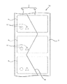
図1に本発明のラベル連続体10を示す。図1(a)はラベル基材側の平面図、図1(b)はb−b線断面図、図1(c)はc−c線断面図である。
FIG. 1 shows a
ラベル連続体10は、ラベル基材5と粘着剤層6とセパレータ7とをこの順に積層した長尺帯状の粘着紙2に、所望サイズのラベル片4の輪郭に応じ、ラベル基材5側から粘着剤層6に至るハーフカットを所定間隔で施したものである。図1に示すラベル連続体は、ラベル片4の周囲のラベルカスと呼ばれる不要な部分を取り除いたものである。符号11はラベル基材5表面に印刷された画像である。
The
セパレータ7には、ラベル連続体10の長手方向に延びた切込み線による背割り8が形成されている。図2にラベル連続体10のセパレータ7側を示す。この背割り8は、ラベル連続体10の長手方法に沿って延び、連続した波線状であり、ラベル連続体10の長手方向と非平行になっている。背割り8の波線は全て曲線で構成され、波線としての振幅の周期はラベル片4の間隔と同期している。
In the
図3はラベル連続体10を巻回したラベルロール12の斜視図である。セパレータ7には背割り8が形成されているが、背割り8の付近が盛り上がることはない。背割り8の切込みが開いて粘着剤層6が露出することもない。ラベル連続体10に施した背割り8は波線形状であるため、ラベル連続体10の流れとともに背割り8の幅方向の位置が変わる。即ちラベル連続体10の搬送とともに背割り8の位置はラベルロール110の一端部側から他端側へと常に変化するため、たとえ背割り8の近辺が僅かずつ盛り上がっていた場合でも、盛り上がる場所が分散する。従って、ラベル連続体10をロール状に巻取ってもラベルロール12の一部が盛り上がったり、膨れることはない。
FIG. 3 is a perspective view of the
図4に本発明のラベル連続体10の別な実施形態を示す。同図は先に説明した図2と同様にセパレータ7側から見た平面図である。図4のラベル連続体の背割り8は、V字形状の切込みを並べた直線の組み合わせで構成されており、ジグザグ状に連なった全ての直線は長手方向と非平行である。ラベル片4一枚に対してV字形状の切込みが一つ形成され、ラベル片4の間隔と切込みの周期とが同期している。この形状の背割り8をラベル連続体10をロール状に巻回した場合でも切込みの位置が幅方向に分散しているため、ロールの一部が盛り上がったり、膨れることはない。
FIG. 4 shows another embodiment of the
図5は直線と曲線を組み合わせた背割り8を形成したラベル連続体10の別な実施形態である。このラベル連続体10をロール状に巻回した場合でも切込みの位置が幅方向に分散しているため、ロールの一部が盛り上がったり、膨れることはない。
FIG. 5 shows another embodiment of the
図6もラベル連続体10の別な実施形態である。同図では、長手方向と非平行な直線をつないだ背割り8を形成してあるが、背割り8の周期をラベル片4の二枚分の送りピッチに同期させている。このように、背割りの周期とラベルの間隔との同期は任意の倍数である。
FIG. 6 is another embodiment of the
図7はラベル連続体10の別な実施の形態を示す図である。図7(a)のラベル連続体10は図1で説明したラベル連続体10のラベル片4とラベル4の間にミシン目13を設けたものである。ミシン目を設けることでラベル片4を一枚あるいは複数枚ごとに切り離し易くしている。例えば、ラベル片4一枚をミシン目13で切り離し、背割り8をきっかけにしてセパレータ7bを剥がし取る。すると図7(b)に示すように、ラベル片4の約半分が粘着剤が露出する。この状態でセパレータ7a側を持てば、粘着剤に一切触らずにラベルを位置決めし、貼り付け作業を行なうことができる。この貼り付け作業は複数枚のラベル片4が連なったラベル連続体10からセパレータ7bを一気に剥がし、ラベル片4を次々に貼り付ける作業にも有効である。
FIG. 7 is a view showing another embodiment of the
前記した実施形態では、背割り8をラベル片4の中央部に設けた例を説明したが、背割り8の幅方向の位置はラベル片4の幅の範囲内であれば、ラベル連続体10の一方の縁に寄っていても良い。また、長手方向において、背割りの周期はラベル片4の間隔と同期させなくても同じ効果を得ることができる。なお、図7で説明したように、片方のセパレータ7bだけを先に剥がす貼り付け方法を採る場合は、背割り8の周期とラベル片4の間隔を同期させておくことが望ましい。同期していない場合はラベル片4ごとに背割り8の位置と形状が異なり、貼り付けの作業効率が低下する恐れがあるからである。
In the above-described embodiment, the example in which the
ラベル基材5の種類や材質は、紙や合成樹脂フィルムなど特に限定されるものではなく、粘着紙として一般的に用いられているものである。例えば、上質紙、コート紙、アート紙のような紙基材、PET(ポリエチレンテレフタレート)、PE(ポリエチレン)、PP(ポリプロピレン)、PS(ポリスチレン)を素材とした合成樹脂フィルムや、前記の合成樹脂を複数種組み合わせたシート、合成樹脂フィルムと紙とを合わせた複合シートも使用できる。感熱紙(サーマル紙)でも構わない。
The type and material of the
粘着剤層6の粘着剤は、例えば、エマルジョン系(粘着剤を水に分散したもの)、ソルベント系(粘着剤を溶剤に溶解したもの)、ホットメルト系(熱可塑性を利用したもの)等である。材質としては、合成ゴム系や天然ゴム系、アクリル樹脂系、ポリビニルエーテル樹脂系、ウレタン樹脂系、シリコーン樹脂系等の粘着剤があげられる。粘着剤の粘着力は任意である。 The pressure-sensitive adhesive of the pressure-sensitive adhesive layer 6 is, for example, an emulsion system (in which the pressure-sensitive adhesive is dispersed in water), a solvent system (in which the pressure-sensitive adhesive is dissolved in a solvent), a hot melt system (using thermoplasticity), or the like. is there. Examples of the material include adhesives such as synthetic rubber, natural rubber, acrylic resin, polyvinyl ether resin, urethane resin, and silicone resin. The adhesive strength of the adhesive is arbitrary.
セパレータ7は汎用のものである。例えば、紙やフィルムに紫外線硬化型のシリコーン、熱硬化型のシリコーン、溶剤型のシリコーン、アルキルペンダントポリマーの他、フッ素系の剥離剤を塗工したものがあげられる。
The
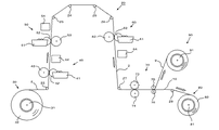
このラベル連続体10の加工方法を図8の凸版輪転印刷機20を用いて説明する。図8の印刷機20は、通紙経路順に、巻出し部30、裏面印刷工程40、第1の表面印刷工程50、第2の表面印刷工程60、背割り工程100、ダイカット工程70、巻き取り部80およびカス巻き取り部90で構成される。
A method of processing the
裏面印刷工程40は、主に版胴42、圧胴43等からなる印刷ユニット41と、その下流に設けられたUVランプ44とからなり、版胴42と圧胴43とで粘着紙2を挟圧して搬送するとともに、版胴42に紫外線硬化型インキ(紫外線の照射により瞬時に硬化するインキ)を供給して粘着紙2に印刷を行う。そしてUVランプ44から紫外線を照射して粘着紙に印刷したインキを硬化させる。粘着紙2のセパレータ側にタイミングマークを印刷する場合はこの印刷ユニット41を用いる。
The back
第1の表面印刷工程50は、主に版胴52、圧胴53等からなる印刷ユニット51と、その下流に設けられたUVランプ54とからなる。
The first
第2の表面印刷工程60は、主に版胴62、圧胴63等からなる印刷ユニット61と、その下流に設けられたUVランプ64とからなる。
The second surface printing step 60 includes a
第1の表面印刷工程50、第2の表面印刷工程60とも、粘着紙2のラベル基材5側に印刷する以外は裏面印刷工程40と同じ構成のため、詳しい説明は省略する。
Since both the first front
背割り工程100は、粘着紙2のセパレータ7に対して長手方向に延びる切込みを設けて背割り8を形成する工程である。ダイロール101と呼ばれる刃付きロールとアンビルロール102との間に粘着紙2を鋏み、ダイロール101をセパレータ7に押し当てて回転させることによりセパレータ7を切込んで行き、背割り8を形成する。
The
ダイカット工程70は粘着紙2のラベル基材5側から粘着剤層6に至るハーフカットを行う工程である。ハーフカット線は、例えば、ダイロール73と呼ばれる刃付きロールとアンビルロール74との間に粘着紙を鋏み、ダイロール73をラベル基材5に押し当てて回転させることにより形成する。ダイロール73の下流には、粘着紙2からラベルカス9を分離する一対のカス取りロール75・76が配置されている。
The die cutting process 70 is a process of performing a half cut from the
巻き取り部80にはラベル連続体10を巻き取る巻き取り軸81が設けられ、カス巻き取り部90にはカスを巻き取る巻き取り軸91が設けられている。
The take-up unit 80 is provided with a take-up
図8において、付番22〜27・29はガイドロールである。 In FIG. 8 , reference numerals 22 to 27 and 29 are guide rolls.
ラベル連続体10は以下のようにして加工する。巻出し部30から巻き出された粘着紙2は、裏面印刷工程40へ送られ、セパレータの裏面に紫外線硬化型インキでタイミングマーク(不図示)が印刷される。印刷されたインキはUVランプ44で瞬時に硬化される。続いて粘着紙2は第1の表面印刷工程50、第2の表面印刷工程60へと搬送され、それぞれの印刷ユニット51・61にてラベル基材面に文字や図柄11(図1等を参照)が紫外線硬化型インキで印刷される。印刷されたインキはUVランプ54・64によって瞬時に硬化される。
The
印刷を終えた粘着紙2は背割り工程100に至り、セパレータ7にダイロール101の刃が押し当てられて切込まれ、背割り8が形成される。セパレータ7は背割り8によって幅方向に2分割された状態になる。ダイロール101の刃はセパレータ7を貫通して粘着剤にやや食い込む程度の深さに設定し、ラベル基材5には到達しない。背割り8の形状はダイロール101外周に形成された刃を展開した形状になる。
The
背割り8が形成された粘着紙2には続いてダイロール73によって所定形状のハーフカットが施される。カス取りロール75でラベルカス9を引き剥がすと、図1等に示したラベル連続体10の元になるマスターロール82が得られる。ラベル連続体10は巻き取り部80の軸81に巻き取られ、マスターロール82が完成する。カス上げされたラベルカス9は、カス巻き取り部90の巻き取り軸91に巻き取られる。
Subsequently, the
本発明のラベル連続体の加工方法によれば、セパレータに背割りを設け、ラベル片を一枚ごとセパレータから剥がし易いラベル連続体を提供できる。得られたラベル連続体は、ロール状に巻いた場合でも背割りの付近が盛り上がることがなく、ラベル片が歪んだりシワが発生することはない。 According to the method for processing a label continuous body of the present invention, it is possible to provide a label continuous body in which the separator is provided with a split and the label pieces are easily peeled from the separator one by one. Even when the obtained label continuous body is rolled up, the vicinity of the back split does not rise, and the label piece is not distorted or wrinkled.
図9に別の加工方法を示す。図9のラベル加工機20は、背割り工程100以外は図8で説明した加工機と同一構成である。背割り工程100は、ガイドロール27で粘着紙2からセパレータ7を剥離し、ラベル基材5および粘着剤層6の積層体3とは別経路を通し、ガイドロール28a、29bの間に設けたダイロール101とアンビルロール102との間にセパレータ7のみを通し、背割り8を形成して行く仕組である。背割り8が形成されたセパレータ7は、下流の対ロール77・78で積層体3と圧着されて元の粘着紙2と同じ断面構造に戻り、ダイカット工程70へと進む。
FIG. 9 shows another processing method. The
図9の加工方法によれば、図8を用いて説明した加工方法の効果に加え、セパレータ7だけに切込み8を入れることができ、より安定したラベル加工が可能になる。誤ってラベル基材5まで深くカットすることが回避される。
According to the processing method of FIG. 9, in addition to the effect of the processing method described with reference to FIG. 8, it is possible to make the
前述した加工方法では背割り工程100およびダイカット工程70にてダイロールとアンビルロールを用いたが、フラットダイを用いても良い。また、ダイロールとしてフレキシブルダイを用いても構わない。
In the processing method described above, the die roll and the anvil roll are used in the
なお、本発明が前述した実施の形態に限定されず、本発明の技術思想の範囲内において、各実施の形態は適宜変更され得ることは明らかである。また、上記構成部材の数、位置、形状、配置等は上記実施の形態に限定されず、本発明を実施する上で好適な数、位置、形状等にすることができる。 It should be noted that the present invention is not limited to the above-described embodiments, and it is obvious that each embodiment can be appropriately changed within the scope of the technical idea of the present invention. In addition, the number, position, shape, arrangement, and the like of the above-described constituent members are not limited to the above-described embodiment, and can be set to a suitable number, position, shape, and the like for carrying out the present invention.
2 粘着紙
4 ラベル片
5 ラベル基材
6 粘着剤層
7 セパレータ
8 背割り(切込み)
9 ラベルカス
10 ラベル連続体
11 文字や画像
12 ラベルロール
13 ミシン目
15 ラベルロール
20 ラベル加工機
30 巻き出し部
40 裏面印刷工程
48 シワ
50 第1の表面印刷工程
60 第2の表面印刷工程
70 ダイカット工程
80 巻き取り部
90 カス巻き取り部
100 背割り工程
101 ダイロール
102 アンビルロール
2
DESCRIPTION OF
Claims (1)
前記粘着紙に所定の情報を印刷する印刷工程と、
ラベル基材と粘着剤層とセパレータとが積層された状態のままで、前記粘着紙のセパレータに、その長手方向に延び、ラベル連続体の長手方向と非平行な直線と曲線の一方または両方で構成され、ラベル連続体におけるラベル片の間隔と同期した周期でラベル連続体の幅方向を往復変位する切込み線からなる背割りを形成する背割り工程と、
前記粘着紙に、ラベル基材側から粘着剤層に至るハーフカットを所定間隔で繰り返し、ハーフカット線でラベル片を区画形成していくダイカット工程と、
前記ハーフカット線で区画されたラベル片の周囲のラベルカスを連続的に除去するカス上げ工程と、
ラベルカスを除去したラベル連続体をラベル基材を外側にしてロール状に巻回する巻取り工程と、
をこの順に含むことを特徴とするラベル連続体の加工方法。 A label continuous body processing method for processing a long strip-shaped adhesive paper in which a label base material, an adhesive layer and a separator are laminated in this order,
A printing step of printing predetermined information on the adhesive paper;
With the label base material, the pressure-sensitive adhesive layer and the separator being laminated, the pressure-sensitive adhesive paper separator extends in the longitudinal direction thereof and is one or both of a straight line and a curve which are not parallel to the longitudinal direction of the label continuous body. A spine splitting step formed of a split line configured to reciprocate in the width direction of the label continuous body at a period synchronized with the interval between the label pieces in the label continuous body ;
In the adhesive paper, a die-cut process in which a half-cut from the label base material side to the adhesive layer is repeated at a predetermined interval, and a label piece is partitioned by a half-cut line, and
A residue raising step for continuously removing the label residue around the label piece defined by the half-cut line;
A winding process in which the label continuum from which the label residue has been removed is wound in a roll shape with the label substrate facing outside;
The label continuous body processing method characterized by including these in this order .
Priority Applications (1)
| Application Number | Priority Date | Filing Date | Title |
|---|---|---|---|
| JP2010050794A JP5566136B2 (en) | 2010-03-08 | 2010-03-08 | Processing method for continuous label |
Applications Claiming Priority (1)
| Application Number | Priority Date | Filing Date | Title |
|---|---|---|---|
| JP2010050794A JP5566136B2 (en) | 2010-03-08 | 2010-03-08 | Processing method for continuous label |
Publications (2)
| Publication Number | Publication Date |
|---|---|
| JP2011186157A JP2011186157A (en) | 2011-09-22 |
| JP5566136B2 true JP5566136B2 (en) | 2014-08-06 |
Family
ID=44792512
Family Applications (1)
| Application Number | Title | Priority Date | Filing Date |
|---|---|---|---|
| JP2010050794A Active JP5566136B2 (en) | 2010-03-08 | 2010-03-08 | Processing method for continuous label |
Country Status (1)
| Country | Link |
|---|---|
| JP (1) | JP5566136B2 (en) |
Families Citing this family (4)
| Publication number | Priority date | Publication date | Assignee | Title |
|---|---|---|---|---|
| GB2524954B8 (en) * | 2014-03-27 | 2017-03-22 | Essentra Packaging & Security Ltd | A peelable label |
| JP6856384B2 (en) * | 2017-01-12 | 2021-04-07 | 藤森工業株式会社 | A method for forming a tear auxiliary line and a forming roller used for the forming method. |
| WO2020065702A1 (en) * | 2018-09-25 | 2020-04-02 | ブラザー工業株式会社 | Long medium and tape cartridge |
| JP6617303B1 (en) * | 2019-04-15 | 2019-12-11 | 株式会社伸和紙工社 | Back splitting machine |
Family Cites Families (4)
| Publication number | Priority date | Publication date | Assignee | Title |
|---|---|---|---|---|
| JPH01181065U (en) * | 1988-06-14 | 1989-12-27 | ||
| JPH0267124A (en) * | 1988-09-01 | 1990-03-07 | Ona Insatsu Kk | Apparatus for preparing label carrier strip |
| JPH08198516A (en) * | 1995-01-24 | 1996-08-06 | Hideichiro Tsuchiya | Tape-cartridge with releasable paper sheet divided into two parts |
| JP4558300B2 (en) * | 2003-10-27 | 2010-10-06 | 株式会社アトラス | Seal sheet |
-
2010
- 2010-03-08 JP JP2010050794A patent/JP5566136B2/en active Active
Also Published As
| Publication number | Publication date |
|---|---|
| JP2011186157A (en) | 2011-09-22 |
Similar Documents
| Publication | Publication Date | Title |
|---|---|---|
| JP5351789B2 (en) | RFID label and method of processing RFID label | |
| US10113088B2 (en) | Label manufacturing method and label | |
| JP5566136B2 (en) | Processing method for continuous label | |
| JP5718704B2 (en) | Processing method for continuous label | |
| JP2010234574A (en) | Method for processing body of label series, and body of label series | |
| JP5441620B2 (en) | RFID label continuum and method of using RFID label | |
| JP6032877B2 (en) | Manufacturing method of label without mount | |
| JP5441594B2 (en) | Labels and label usage | |
| JP5619641B2 (en) | Label continuum, label continuum processing method | |
| JP5628697B2 (en) | Label roll manufacturing method | |
| JP5441595B2 (en) | Label continuum | |
| JP2009119687A (en) | Reinforcing method, label processing method and label forming apparatus | |
| JP6509557B2 (en) | Apparatus and method for manufacturing perforated label continuum | |
| JP2008044171A (en) | Reinforcing method, label processing method, attaching apparatus and label processing apparatus | |
| JP5980482B2 (en) | Label processing method | |
| JP7280087B2 (en) | Continuous label manufacturing apparatus and continuous label manufacturing method | |
| JP3905605B2 (en) | Film pasting method and apparatus | |
| WO2022163112A1 (en) | Rfid label, rfid recording medium, and method for manufacturing rfid label | |
| JP2003036026A (en) | Label serial body without mount and production method for label serial body without mount | |
| JP2015197618A (en) | Label sheet and manufacturing method of the same | |
| JP2013078912A (en) | Delivery slip with noshi | |
| JP6096252B2 (en) | label | |
| JP6104585B2 (en) | Non-mounting label printing processing small winding device and non-mounting label printing processing small winding method | |
| JP4917334B2 (en) | Method and apparatus for manufacturing connecting sheet for printer | |
| JP2015010123A (en) | Method of producing roll-state tape |
Legal Events
| Date | Code | Title | Description |
|---|---|---|---|
| A621 | Written request for application examination |
Free format text: JAPANESE INTERMEDIATE CODE: A621 Effective date: 20130228 |
|
| A711 | Notification of change in applicant |
Free format text: JAPANESE INTERMEDIATE CODE: A712 Effective date: 20130418 |
|
| A977 | Report on retrieval |
Free format text: JAPANESE INTERMEDIATE CODE: A971007 Effective date: 20130920 |
|
| A131 | Notification of reasons for refusal |
Free format text: JAPANESE INTERMEDIATE CODE: A131 Effective date: 20131001 |
|
| A521 | Request for written amendment filed |
Free format text: JAPANESE INTERMEDIATE CODE: A523 Effective date: 20131127 |
|
| TRDD | Decision of grant or rejection written | ||
| A01 | Written decision to grant a patent or to grant a registration (utility model) |
Free format text: JAPANESE INTERMEDIATE CODE: A01 Effective date: 20140617 |
|
| A61 | First payment of annual fees (during grant procedure) |
Free format text: JAPANESE INTERMEDIATE CODE: A61 Effective date: 20140617 |
|
| R150 | Certificate of patent or registration of utility model |
Ref document number: 5566136 Country of ref document: JP Free format text: JAPANESE INTERMEDIATE CODE: R150 |
|
| R250 | Receipt of annual fees |
Free format text: JAPANESE INTERMEDIATE CODE: R250 |
|
| R250 | Receipt of annual fees |
Free format text: JAPANESE INTERMEDIATE CODE: R250 |
|
| R250 | Receipt of annual fees |
Free format text: JAPANESE INTERMEDIATE CODE: R250 |
|
| R250 | Receipt of annual fees |
Free format text: JAPANESE INTERMEDIATE CODE: R250 |
|
| R250 | Receipt of annual fees |
Free format text: JAPANESE INTERMEDIATE CODE: R250 |
|
| R250 | Receipt of annual fees |
Free format text: JAPANESE INTERMEDIATE CODE: R250 |
|
| R250 | Receipt of annual fees |
Free format text: JAPANESE INTERMEDIATE CODE: R250 |