JP5561991B2 - Electrostatic atomizer - Google Patents
Electrostatic atomizer Download PDFInfo
- Publication number
- JP5561991B2 JP5561991B2 JP2009234209A JP2009234209A JP5561991B2 JP 5561991 B2 JP5561991 B2 JP 5561991B2 JP 2009234209 A JP2009234209 A JP 2009234209A JP 2009234209 A JP2009234209 A JP 2009234209A JP 5561991 B2 JP5561991 B2 JP 5561991B2
- Authority
- JP
- Japan
- Prior art keywords
- electrostatic atomizer
- pin member
- mist
- water
- aqueous solution
- Prior art date
- Legal status (The legal status is an assumption and is not a legal conclusion. Google has not performed a legal analysis and makes no representation as to the accuracy of the status listed.)
- Active
Links
- XLYOFNOQVPJJNP-UHFFFAOYSA-N water Substances O XLYOFNOQVPJJNP-UHFFFAOYSA-N 0.000 claims description 71
- 239000003595 mist Substances 0.000 claims description 60
- 239000000463 material Substances 0.000 claims description 50
- 229910052751 metal Inorganic materials 0.000 claims description 47
- 239000002184 metal Substances 0.000 claims description 47
- 239000007864 aqueous solution Substances 0.000 claims description 46
- BASFCYQUMIYNBI-UHFFFAOYSA-N platinum Chemical compound [Pt] BASFCYQUMIYNBI-UHFFFAOYSA-N 0.000 claims description 22
- 238000004378 air conditioning Methods 0.000 claims description 12
- 229910052697 platinum Inorganic materials 0.000 claims description 11
- PCHJSUWPFVWCPO-UHFFFAOYSA-N gold Chemical compound [Au] PCHJSUWPFVWCPO-UHFFFAOYSA-N 0.000 claims description 8
- 229910052737 gold Inorganic materials 0.000 claims description 8
- 239000010931 gold Substances 0.000 claims description 8
- 239000000203 mixture Substances 0.000 claims description 8
- 239000000835 fiber Substances 0.000 description 34
- 239000002105 nanoparticle Substances 0.000 description 11
- -1 polypropylene Polymers 0.000 description 11
- 239000002245 particle Substances 0.000 description 10
- 150000002500 ions Chemical class 0.000 description 9
- 238000010521 absorption reaction Methods 0.000 description 8
- 239000000919 ceramic Substances 0.000 description 8
- VYPSYNLAJGMNEJ-UHFFFAOYSA-N Silicium dioxide Chemical compound O=[Si]=O VYPSYNLAJGMNEJ-UHFFFAOYSA-N 0.000 description 7
- 239000007788 liquid Substances 0.000 description 7
- KDLHZDBZIXYQEI-UHFFFAOYSA-N Palladium Chemical compound [Pd] KDLHZDBZIXYQEI-UHFFFAOYSA-N 0.000 description 6
- CIWBSHSKHKDKBQ-JLAZNSOCSA-N Ascorbic acid Chemical compound OC[C@H](O)[C@H]1OC(=O)C(O)=C1O CIWBSHSKHKDKBQ-JLAZNSOCSA-N 0.000 description 5
- CBENFWSGALASAD-UHFFFAOYSA-N Ozone Chemical compound [O-][O+]=O CBENFWSGALASAD-UHFFFAOYSA-N 0.000 description 5
- 229910010293 ceramic material Inorganic materials 0.000 description 5
- 229920005989 resin Polymers 0.000 description 5
- 239000011347 resin Substances 0.000 description 5
- 229930003231 vitamin Natural products 0.000 description 5
- 239000011782 vitamin Substances 0.000 description 5
- 235000013343 vitamin Nutrition 0.000 description 5
- 229940088594 vitamin Drugs 0.000 description 5
- PPBRXRYQALVLMV-UHFFFAOYSA-N Styrene Chemical compound C=CC1=CC=CC=C1 PPBRXRYQALVLMV-UHFFFAOYSA-N 0.000 description 4
- 230000000844 anti-bacterial effect Effects 0.000 description 4
- 125000003178 carboxy group Chemical group [H]OC(*)=O 0.000 description 4
- 230000001143 conditioned effect Effects 0.000 description 4
- 230000001877 deodorizing effect Effects 0.000 description 4
- 239000010419 fine particle Substances 0.000 description 4
- 239000007769 metal material Substances 0.000 description 4
- 229920001778 nylon Polymers 0.000 description 4
- 229920000728 polyester Polymers 0.000 description 4
- 230000001954 sterilising effect Effects 0.000 description 4
- 238000003860 storage Methods 0.000 description 4
- 239000000057 synthetic resin Substances 0.000 description 4
- 229920003002 synthetic resin Polymers 0.000 description 4
- RYGMFSIKBFXOCR-UHFFFAOYSA-N Copper Chemical compound [Cu] RYGMFSIKBFXOCR-UHFFFAOYSA-N 0.000 description 3
- 229920000297 Rayon Polymers 0.000 description 3
- FAPWRFPIFSIZLT-UHFFFAOYSA-M Sodium chloride Chemical compound [Na+].[Cl-] FAPWRFPIFSIZLT-UHFFFAOYSA-M 0.000 description 3
- RTAQQCXQSZGOHL-UHFFFAOYSA-N Titanium Chemical compound [Ti] RTAQQCXQSZGOHL-UHFFFAOYSA-N 0.000 description 3
- ADRVNXBAWSRFAJ-UHFFFAOYSA-N catechin Natural products OC1Cc2cc(O)cc(O)c2OC1c3ccc(O)c(O)c3 ADRVNXBAWSRFAJ-UHFFFAOYSA-N 0.000 description 3
- 235000005487 catechin Nutrition 0.000 description 3
- 239000003795 chemical substances by application Substances 0.000 description 3
- KRKNYBCHXYNGOX-UHFFFAOYSA-N citric acid Chemical compound OC(=O)CC(O)(C(O)=O)CC(O)=O KRKNYBCHXYNGOX-UHFFFAOYSA-N 0.000 description 3
- 229910052802 copper Inorganic materials 0.000 description 3
- 239000010949 copper Substances 0.000 description 3
- 238000004332 deodorization Methods 0.000 description 3
- 238000010586 diagram Methods 0.000 description 3
- 239000003365 glass fiber Substances 0.000 description 3
- 229910052763 palladium Inorganic materials 0.000 description 3
- 239000002964 rayon Substances 0.000 description 3
- 230000000717 retained effect Effects 0.000 description 3
- 239000000377 silicon dioxide Substances 0.000 description 3
- 239000004332 silver Substances 0.000 description 3
- 230000002269 spontaneous effect Effects 0.000 description 3
- 239000000126 substance Substances 0.000 description 3
- 229910052719 titanium Inorganic materials 0.000 description 3
- 239000010936 titanium Substances 0.000 description 3
- KIUKXJAPPMFGSW-DNGZLQJQSA-N (2S,3S,4S,5R,6R)-6-[(2S,3R,4R,5S,6R)-3-Acetamido-2-[(2S,3S,4R,5R,6R)-6-[(2R,3R,4R,5S,6R)-3-acetamido-2,5-dihydroxy-6-(hydroxymethyl)oxan-4-yl]oxy-2-carboxy-4,5-dihydroxyoxan-3-yl]oxy-5-hydroxy-6-(hydroxymethyl)oxan-4-yl]oxy-3,4,5-trihydroxyoxane-2-carboxylic acid Chemical compound CC(=O)N[C@H]1[C@H](O)O[C@H](CO)[C@@H](O)[C@@H]1O[C@H]1[C@H](O)[C@@H](O)[C@H](O[C@H]2[C@@H]([C@@H](O[C@H]3[C@@H]([C@@H](O)[C@H](O)[C@H](O3)C(O)=O)O)[C@H](O)[C@@H](CO)O2)NC(C)=O)[C@@H](C(O)=O)O1 KIUKXJAPPMFGSW-DNGZLQJQSA-N 0.000 description 2
- 241000894006 Bacteria Species 0.000 description 2
- 102000008186 Collagen Human genes 0.000 description 2
- 108010035532 Collagen Proteins 0.000 description 2
- ZZZCUOFIHGPKAK-UHFFFAOYSA-N D-erythro-ascorbic acid Natural products OCC1OC(=O)C(O)=C1O ZZZCUOFIHGPKAK-UHFFFAOYSA-N 0.000 description 2
- CPLXHLVBOLITMK-UHFFFAOYSA-N Magnesium oxide Chemical compound [Mg]=O CPLXHLVBOLITMK-UHFFFAOYSA-N 0.000 description 2
- DATAGRPVKZEWHA-YFKPBYRVSA-N N(5)-ethyl-L-glutamine Chemical compound CCNC(=O)CC[C@H]([NH3+])C([O-])=O DATAGRPVKZEWHA-YFKPBYRVSA-N 0.000 description 2
- 239000004677 Nylon Substances 0.000 description 2
- 229920002845 Poly(methacrylic acid) Polymers 0.000 description 2
- BQCADISMDOOEFD-UHFFFAOYSA-N Silver Chemical compound [Ag] BQCADISMDOOEFD-UHFFFAOYSA-N 0.000 description 2
- 229920002125 Sokalan® Polymers 0.000 description 2
- 244000269722 Thea sinensis Species 0.000 description 2
- GWEVSGVZZGPLCZ-UHFFFAOYSA-N Titan oxide Chemical compound O=[Ti]=O GWEVSGVZZGPLCZ-UHFFFAOYSA-N 0.000 description 2
- 229930003268 Vitamin C Natural products 0.000 description 2
- MCMNRKCIXSYSNV-UHFFFAOYSA-N Zirconium dioxide Chemical compound O=[Zr]=O MCMNRKCIXSYSNV-UHFFFAOYSA-N 0.000 description 2
- NIXOWILDQLNWCW-UHFFFAOYSA-N acrylic acid group Chemical group C(C=C)(=O)O NIXOWILDQLNWCW-UHFFFAOYSA-N 0.000 description 2
- 150000001413 amino acids Chemical class 0.000 description 2
- 239000012298 atmosphere Substances 0.000 description 2
- 238000000889 atomisation Methods 0.000 description 2
- FUWUEFKEXZQKKA-UHFFFAOYSA-N beta-thujaplicin Chemical compound CC(C)C=1C=CC=C(O)C(=O)C=1 FUWUEFKEXZQKKA-UHFFFAOYSA-N 0.000 description 2
- 239000011230 binding agent Substances 0.000 description 2
- RYYVLZVUVIJVGH-UHFFFAOYSA-N caffeine Chemical compound CN1C(=O)N(C)C(=O)C2=C1N=CN2C RYYVLZVUVIJVGH-UHFFFAOYSA-N 0.000 description 2
- 150000001765 catechin Chemical class 0.000 description 2
- 125000002091 cationic group Chemical group 0.000 description 2
- 229920001436 collagen Polymers 0.000 description 2
- 150000001875 compounds Chemical class 0.000 description 2
- KZHJGOXRZJKJNY-UHFFFAOYSA-N dioxosilane;oxo(oxoalumanyloxy)alumane Chemical compound O=[Si]=O.O=[Si]=O.O=[Al]O[Al]=O.O=[Al]O[Al]=O.O=[Al]O[Al]=O KZHJGOXRZJKJNY-UHFFFAOYSA-N 0.000 description 2
- 238000009826 distribution Methods 0.000 description 2
- 150000002148 esters Chemical class 0.000 description 2
- RWSXRVCMGQZWBV-WDSKDSINSA-N glutathione Chemical compound OC(=O)[C@@H](N)CCC(=O)N[C@@H](CS)C(=O)NCC(O)=O RWSXRVCMGQZWBV-WDSKDSINSA-N 0.000 description 2
- 229920002674 hyaluronan Polymers 0.000 description 2
- 229960003160 hyaluronic acid Drugs 0.000 description 2
- 239000002923 metal particle Substances 0.000 description 2
- 238000000034 method Methods 0.000 description 2
- 229910052863 mullite Inorganic materials 0.000 description 2
- 229910000510 noble metal Inorganic materials 0.000 description 2
- 239000004584 polyacrylic acid Substances 0.000 description 2
- 229910052700 potassium Inorganic materials 0.000 description 2
- 229910052709 silver Inorganic materials 0.000 description 2
- 238000005245 sintering Methods 0.000 description 2
- 229910052708 sodium Inorganic materials 0.000 description 2
- 239000011734 sodium Substances 0.000 description 2
- 239000011780 sodium chloride Substances 0.000 description 2
- 239000000758 substrate Substances 0.000 description 2
- 239000004094 surface-active agent Substances 0.000 description 2
- 229920002803 thermoplastic polyurethane Polymers 0.000 description 2
- 238000009423 ventilation Methods 0.000 description 2
- 235000019154 vitamin C Nutrition 0.000 description 2
- 239000011718 vitamin C Substances 0.000 description 2
- 150000003722 vitamin derivatives Chemical class 0.000 description 2
- PFTAWBLQPZVEMU-DZGCQCFKSA-N (+)-catechin Chemical compound C1([C@H]2OC3=CC(O)=CC(O)=C3C[C@@H]2O)=CC=C(O)C(O)=C1 PFTAWBLQPZVEMU-DZGCQCFKSA-N 0.000 description 1
- FPIPGXGPPPQFEQ-UHFFFAOYSA-N 13-cis retinol Natural products OCC=C(C)C=CC=C(C)C=CC1=C(C)CCCC1(C)C FPIPGXGPPPQFEQ-UHFFFAOYSA-N 0.000 description 1
- 239000005995 Aluminium silicate Substances 0.000 description 1
- 244000025254 Cannabis sativa Species 0.000 description 1
- 235000012766 Cannabis sativa ssp. sativa var. sativa Nutrition 0.000 description 1
- 235000012765 Cannabis sativa ssp. sativa var. spontanea Nutrition 0.000 description 1
- 235000009024 Ceanothus sanguineus Nutrition 0.000 description 1
- 229920002101 Chitin Polymers 0.000 description 1
- 229920001661 Chitosan Polymers 0.000 description 1
- 244000223760 Cinnamomum zeylanicum Species 0.000 description 1
- 240000000560 Citrus x paradisi Species 0.000 description 1
- 229920000742 Cotton Polymers 0.000 description 1
- 229920000858 Cyclodextrin Polymers 0.000 description 1
- 240000004784 Cymbopogon citratus Species 0.000 description 1
- 235000017897 Cymbopogon citratus Nutrition 0.000 description 1
- JOYRKODLDBILNP-UHFFFAOYSA-N Ethyl urethane Chemical compound CCOC(N)=O JOYRKODLDBILNP-UHFFFAOYSA-N 0.000 description 1
- 241000233866 Fungi Species 0.000 description 1
- 108010024636 Glutathione Proteins 0.000 description 1
- PEDCQBHIVMGVHV-UHFFFAOYSA-N Glycerol Natural products OCC(O)CO PEDCQBHIVMGVHV-UHFFFAOYSA-N 0.000 description 1
- LPHGQDQBBGAPDZ-UHFFFAOYSA-N Isocaffeine Natural products CN1C(=O)N(C)C(=O)C2=C1N(C)C=N2 LPHGQDQBBGAPDZ-UHFFFAOYSA-N 0.000 description 1
- 235000010254 Jasminum officinale Nutrition 0.000 description 1
- 240000005385 Jasminum sambac Species 0.000 description 1
- 239000005909 Kieselgur Substances 0.000 description 1
- 239000002211 L-ascorbic acid Substances 0.000 description 1
- 235000000069 L-ascorbic acid Nutrition 0.000 description 1
- 244000178870 Lavandula angustifolia Species 0.000 description 1
- 235000010663 Lavandula angustifolia Nutrition 0.000 description 1
- 240000003553 Leptospermum scoparium Species 0.000 description 1
- 235000015459 Lycium barbarum Nutrition 0.000 description 1
- WHNWPMSKXPGLAX-UHFFFAOYSA-N N-Vinyl-2-pyrrolidone Chemical compound C=CN1CCCC1=O WHNWPMSKXPGLAX-UHFFFAOYSA-N 0.000 description 1
- 229910019142 PO4 Inorganic materials 0.000 description 1
- 239000004743 Polypropylene Substances 0.000 description 1
- 239000004372 Polyvinyl alcohol Substances 0.000 description 1
- 241000241413 Propolis Species 0.000 description 1
- 244000178231 Rosmarinus officinalis Species 0.000 description 1
- 241000533293 Sesbania emerus Species 0.000 description 1
- 229910021607 Silver chloride Inorganic materials 0.000 description 1
- 235000016639 Syzygium aromaticum Nutrition 0.000 description 1
- 244000223014 Syzygium aromaticum Species 0.000 description 1
- ATJFFYVFTNAWJD-UHFFFAOYSA-N Tin Chemical compound [Sn] ATJFFYVFTNAWJD-UHFFFAOYSA-N 0.000 description 1
- FPIPGXGPPPQFEQ-BOOMUCAASA-N Vitamin A Natural products OC/C=C(/C)\C=C\C=C(\C)/C=C/C1=C(C)CCCC1(C)C FPIPGXGPPPQFEQ-BOOMUCAASA-N 0.000 description 1
- 229930003270 Vitamin B Natural products 0.000 description 1
- 229930003316 Vitamin D Natural products 0.000 description 1
- QYSXJUFSXHHAJI-XFEUOLMDSA-N Vitamin D3 Natural products C1(/[C@@H]2CC[C@@H]([C@]2(CCC1)C)[C@H](C)CCCC(C)C)=C/C=C1\C[C@@H](O)CCC1=C QYSXJUFSXHHAJI-XFEUOLMDSA-N 0.000 description 1
- 244000195452 Wasabia japonica Species 0.000 description 1
- 235000000760 Wasabia japonica Nutrition 0.000 description 1
- 229910021536 Zeolite Inorganic materials 0.000 description 1
- RCDVZFPVEDSBIY-PQYRJTSOSA-M [Na+].OP(O)(O)=O.OC[C@H](O)[C@H]1OC(=O)C(O)=C1[O-] Chemical compound [Na+].OP(O)(O)=O.OC[C@H](O)[C@H]1OC(=O)C(O)=C1[O-] RCDVZFPVEDSBIY-PQYRJTSOSA-M 0.000 description 1
- 239000002253 acid Substances 0.000 description 1
- 229910052783 alkali metal Inorganic materials 0.000 description 1
- FPIPGXGPPPQFEQ-OVSJKPMPSA-N all-trans-retinol Chemical compound OC\C=C(/C)\C=C\C=C(/C)\C=C\C1=C(C)CCCC1(C)C FPIPGXGPPPQFEQ-OVSJKPMPSA-N 0.000 description 1
- TUFYVOCKVJOUIR-UHFFFAOYSA-N alpha-Thujaplicin Natural products CC(C)C=1C=CC=CC(=O)C=1O TUFYVOCKVJOUIR-UHFFFAOYSA-N 0.000 description 1
- PNEYBMLMFCGWSK-UHFFFAOYSA-N aluminium oxide Inorganic materials [O-2].[O-2].[O-2].[Al+3].[Al+3] PNEYBMLMFCGWSK-UHFFFAOYSA-N 0.000 description 1
- 235000012211 aluminium silicate Nutrition 0.000 description 1
- 125000000129 anionic group Chemical group 0.000 description 1
- 230000000843 anti-fungal effect Effects 0.000 description 1
- 230000000845 anti-microbial effect Effects 0.000 description 1
- 230000000840 anti-viral effect Effects 0.000 description 1
- 239000003963 antioxidant agent Substances 0.000 description 1
- 230000003078 antioxidant effect Effects 0.000 description 1
- 235000006708 antioxidants Nutrition 0.000 description 1
- 238000000222 aromatherapy Methods 0.000 description 1
- 229960005070 ascorbic acid Drugs 0.000 description 1
- 229960000892 attapulgite Drugs 0.000 description 1
- 230000003385 bacteriostatic effect Effects 0.000 description 1
- 239000000440 bentonite Substances 0.000 description 1
- 229910000278 bentonite Inorganic materials 0.000 description 1
- SVPXDRXYRYOSEX-UHFFFAOYSA-N bentoquatam Chemical compound O.O=[Si]=O.O=[Al]O[Al]=O SVPXDRXYRYOSEX-UHFFFAOYSA-N 0.000 description 1
- 238000007664 blowing Methods 0.000 description 1
- 229960001948 caffeine Drugs 0.000 description 1
- VJEONQKOZGKCAK-UHFFFAOYSA-N caffeine Natural products CN1C(=O)N(C)C(=O)C2=C1C=CN2C VJEONQKOZGKCAK-UHFFFAOYSA-N 0.000 description 1
- 235000009120 camo Nutrition 0.000 description 1
- 239000003990 capacitor Substances 0.000 description 1
- BVKZGUZCCUSVTD-UHFFFAOYSA-N carbonic acid Chemical compound OC(O)=O BVKZGUZCCUSVTD-UHFFFAOYSA-N 0.000 description 1
- 235000005607 chanvre indien Nutrition 0.000 description 1
- 238000006243 chemical reaction Methods 0.000 description 1
- 229950001002 cianidanol Drugs 0.000 description 1
- 235000017803 cinnamon Nutrition 0.000 description 1
- 239000000084 colloidal system Substances 0.000 description 1
- 238000004891 communication Methods 0.000 description 1
- 238000013329 compounding Methods 0.000 description 1
- 238000009833 condensation Methods 0.000 description 1
- 230000005494 condensation Effects 0.000 description 1
- 235000009508 confectionery Nutrition 0.000 description 1
- 238000001816 cooling Methods 0.000 description 1
- 238000005260 corrosion Methods 0.000 description 1
- 230000007797 corrosion Effects 0.000 description 1
- 238000000354 decomposition reaction Methods 0.000 description 1
- 235000014113 dietary fatty acids Nutrition 0.000 description 1
- HNPSIPDUKPIQMN-UHFFFAOYSA-N dioxosilane;oxo(oxoalumanyloxy)alumane Chemical compound O=[Si]=O.O=[Al]O[Al]=O HNPSIPDUKPIQMN-UHFFFAOYSA-N 0.000 description 1
- WNAHIZMDSQCWRP-UHFFFAOYSA-N dodecane-1-thiol Chemical compound CCCCCCCCCCCCS WNAHIZMDSQCWRP-UHFFFAOYSA-N 0.000 description 1
- 230000000694 effects Effects 0.000 description 1
- 230000005611 electricity Effects 0.000 description 1
- 238000005868 electrolysis reaction Methods 0.000 description 1
- 230000001747 exhibiting effect Effects 0.000 description 1
- 239000000194 fatty acid Substances 0.000 description 1
- 229930195729 fatty acid Natural products 0.000 description 1
- 239000010433 feldspar Substances 0.000 description 1
- 239000002657 fibrous material Substances 0.000 description 1
- 239000006260 foam Substances 0.000 description 1
- 229960003180 glutathione Drugs 0.000 description 1
- 235000011187 glycerol Nutrition 0.000 description 1
- 230000009931 harmful effect Effects 0.000 description 1
- 238000010438 heat treatment Methods 0.000 description 1
- 239000011487 hemp Substances 0.000 description 1
- 238000009434 installation Methods 0.000 description 1
- 238000005304 joining Methods 0.000 description 1
- NLYAJNPCOHFWQQ-UHFFFAOYSA-N kaolin Chemical compound O.O.O=[Al]O[Si](=O)O[Si](=O)O[Al]=O NLYAJNPCOHFWQQ-UHFFFAOYSA-N 0.000 description 1
- 238000004898 kneading Methods 0.000 description 1
- 238000009940 knitting Methods 0.000 description 1
- 239000001102 lavandula vera Substances 0.000 description 1
- 235000018219 lavender Nutrition 0.000 description 1
- 229940074358 magnesium ascorbate Drugs 0.000 description 1
- QYGOVAAVJIUDOO-PQYRJTSOSA-L magnesium dihydrogen phosphate (2R)-2-[(1S)-1,2-dihydroxyethyl]-3-hydroxy-5-oxo-2H-furan-4-olate Chemical compound O=C1C(O)=C([O-])[C@H](O1)[C@@H](O)CO.P(=O)([O-])(O)O.[Mg+2] QYGOVAAVJIUDOO-PQYRJTSOSA-L 0.000 description 1
- 239000000395 magnesium oxide Substances 0.000 description 1
- AIOKQVJVNPDJKA-ZZMNMWMASA-L magnesium;(2r)-2-[(1s)-1,2-dihydroxyethyl]-4-hydroxy-5-oxo-2h-furan-3-olate Chemical compound [Mg+2].OC[C@H](O)[C@H]1OC(=O)C(O)=C1[O-].OC[C@H](O)[C@H]1OC(=O)C(O)=C1[O-] AIOKQVJVNPDJKA-ZZMNMWMASA-L 0.000 description 1
- 150000002739 metals Chemical class 0.000 description 1
- 229920000609 methyl cellulose Polymers 0.000 description 1
- 239000001923 methylcellulose Substances 0.000 description 1
- 230000003020 moisturizing effect Effects 0.000 description 1
- 150000007524 organic acids Chemical class 0.000 description 1
- 239000011368 organic material Substances 0.000 description 1
- 229910052625 palygorskite Inorganic materials 0.000 description 1
- 239000001814 pectin Substances 0.000 description 1
- 235000010987 pectin Nutrition 0.000 description 1
- 229920001277 pectin Polymers 0.000 description 1
- 239000010451 perlite Substances 0.000 description 1
- 235000019362 perlite Nutrition 0.000 description 1
- 239000010452 phosphate Substances 0.000 description 1
- NBIIXXVUZAFLBC-UHFFFAOYSA-K phosphate Chemical compound [O-]P([O-])([O-])=O NBIIXXVUZAFLBC-UHFFFAOYSA-K 0.000 description 1
- 229920001155 polypropylene Polymers 0.000 description 1
- 229920000136 polysorbate Polymers 0.000 description 1
- 229950008882 polysorbate Drugs 0.000 description 1
- 229920002635 polyurethane Polymers 0.000 description 1
- 239000004814 polyurethane Substances 0.000 description 1
- 229920002451 polyvinyl alcohol Polymers 0.000 description 1
- 229920000036 polyvinylpyrrolidone Polymers 0.000 description 1
- 239000001267 polyvinylpyrrolidone Substances 0.000 description 1
- 235000013855 polyvinylpyrrolidone Nutrition 0.000 description 1
- 239000011148 porous material Substances 0.000 description 1
- 239000000843 powder Substances 0.000 description 1
- 229940069949 propolis Drugs 0.000 description 1
- 239000001397 quillaja saponaria molina bark Substances 0.000 description 1
- 238000003303 reheating Methods 0.000 description 1
- 239000005871 repellent Substances 0.000 description 1
- 230000002940 repellent Effects 0.000 description 1
- 235000002020 sage Nutrition 0.000 description 1
- 150000003839 salts Chemical class 0.000 description 1
- 229930182490 saponin Natural products 0.000 description 1
- 150000007949 saponins Chemical class 0.000 description 1
- 235000017709 saponins Nutrition 0.000 description 1
- HFHDHCJBZVLPGP-UHFFFAOYSA-N schardinger α-dextrin Chemical compound O1C(C(C2O)O)C(CO)OC2OC(C(C2O)O)C(CO)OC2OC(C(C2O)O)C(CO)OC2OC(C(O)C2O)C(CO)OC2OC(C(C2O)O)C(CO)OC2OC2C(O)C(O)C1OC2CO HFHDHCJBZVLPGP-UHFFFAOYSA-N 0.000 description 1
- 230000001568 sexual effect Effects 0.000 description 1
- 150000004760 silicates Chemical class 0.000 description 1
- 229910052851 sillimanite Inorganic materials 0.000 description 1
- 239000000243 solution Substances 0.000 description 1
- 229910001220 stainless steel Inorganic materials 0.000 description 1
- 239000010935 stainless steel Substances 0.000 description 1
- 230000003068 static effect Effects 0.000 description 1
- 238000004659 sterilization and disinfection Methods 0.000 description 1
- QAOWNCQODCNURD-UHFFFAOYSA-N sulfuric acid Substances OS(O)(=O)=O QAOWNCQODCNURD-UHFFFAOYSA-N 0.000 description 1
- 235000018553 tannin Nutrition 0.000 description 1
- 229920001864 tannin Polymers 0.000 description 1
- 239000001648 tannin Substances 0.000 description 1
- 229940026510 theanine Drugs 0.000 description 1
- 239000002562 thickening agent Substances 0.000 description 1
- 229910052718 tin Inorganic materials 0.000 description 1
- 239000011135 tin Substances 0.000 description 1
- 239000011882 ultra-fine particle Substances 0.000 description 1
- 239000011719 vitamin A Substances 0.000 description 1
- 235000019155 vitamin A Nutrition 0.000 description 1
- 239000011720 vitamin B Substances 0.000 description 1
- 235000019156 vitamin B Nutrition 0.000 description 1
- 239000011710 vitamin D Substances 0.000 description 1
- 235000019166 vitamin D Nutrition 0.000 description 1
- 150000003710 vitamin D derivatives Chemical class 0.000 description 1
- 229940045997 vitamin a Drugs 0.000 description 1
- 229940046008 vitamin d Drugs 0.000 description 1
- 239000000341 volatile oil Substances 0.000 description 1
- 238000009736 wetting Methods 0.000 description 1
- 210000002268 wool Anatomy 0.000 description 1
- 239000010457 zeolite Substances 0.000 description 1
- 229930007845 β-thujaplicin Natural products 0.000 description 1
Images


Landscapes
- Air-Conditioning For Vehicles (AREA)
- Disinfection, Sterilisation Or Deodorisation Of Air (AREA)
- Special Spraying Apparatus (AREA)
- Electrostatic Spraying Apparatus (AREA)
Description
本発明は、金属ナノコロイドや機能性成分を含む水溶液を超微細なミストとして、空気中、例えば車の室内等に放出する静電霧化装置に関するものである。 The present invention relates to an electrostatic atomizer that discharges an aqueous solution containing a metal nanocolloid or a functional component as an ultrafine mist into the air, for example, a car interior.
従来より、エアコンや空気清浄機では、フィルターを利用して室内環境を改善した。更に近年は、エアコンや空気清浄機からミストを放出し、室内の湿度調節や脱臭、除菌効果も期待できる商品が販売されている。 Conventionally, air conditioners and air purifiers have improved indoor environments using filters. Furthermore, in recent years, products that release mist from air conditioners and air purifiers and can be expected to control indoor humidity, deodorize, and disinfect bacteria have been sold.
これらを空気中に放出させる手段として、例えば空気清浄機や加湿器などに内蔵され液体を霧化する霧化装置として、超音波を利用して液体を霧化する超音波霧化装置が知られている。一般に、超音波霧化装置は、超音波を発生する超音波発生手段として圧電素子を備えており、超音波発生手段から出力された超音波により、霧化対象の不揮発性機能性成分含有液をミストとして放出することが可能である。しかし、超音波により発生させたミストは粒子が目視可能な程度に大きく、湿度過剰や濡れが生じて腐食やカビなどを発生させることがあった。 As means for releasing these components into the air, for example, as an atomizing device built in an air purifier or a humidifier to atomize a liquid, an ultrasonic atomizing device that atomizes the liquid using ultrasonic waves is known. ing. In general, an ultrasonic atomizer includes a piezoelectric element as an ultrasonic wave generating unit that generates ultrasonic waves, and a non-volatile functional component-containing liquid to be atomized is generated by ultrasonic waves output from the ultrasonic wave generating unit. It can be released as mist. However, the mist generated by ultrasonic waves is so large that the particles can be visually observed, and excessive humidity or wetting may occur, causing corrosion or mold.
また、液体を霧化する霧化装置としては、超音波霧化装置の他に、特許文献1に開示されているように、キャピラリ電極またはキャピラリ電極及び対極電極に高電圧を印加することにより液体を霧化する静電霧化装置が知られている。
この種の静電霧化装置としては、例えば、液体を入れた容器と、容器から液体を吸い上げるキャピラリ(細管)と、キャピラリの備えた電極と接地極との間に高電圧を印加する高電圧電源とを有しているものが知られている。
Further, as an atomizing device for atomizing a liquid, in addition to an ultrasonic atomizing device, as disclosed in
As this type of electrostatic atomizer, for example, a high voltage that applies a high voltage between a container containing a liquid, a capillary (capillary tube) that draws the liquid from the container, and an electrode provided on the capillary and a ground electrode What has a power supply is known.
このように、近年、エアコンや空気清浄機では、フィルターを利用して空気を清浄化し、在室者に快適な室内環境を提供している。更に近年は、エアコンや空気清浄機からミストを放出し、室内の湿度調節や脱臭、除菌効果も期待できる商品が販売されている。 As described above, in recent years, air conditioners and air purifiers use a filter to clean the air and provide a comfortable indoor environment for the occupants. Furthermore, in recent years, products that release mist from air conditioners and air purifiers and can be expected to control indoor humidity, deodorize, and disinfect bacteria have been sold.
また、エアコンや空気清浄機、加湿器などでは、室内環境を改善する手段として、コロナ放電を利用したマイナスイオンの発生装置や、水を蒸発させてミストを放出する加湿装置や電気分解を利用したアルカリイオン水のミストを付属機能として装備することがなされている。
例えば、水保持部内に収容されている水に負電圧を印加する印加電極と、接地されている対向電極と、前記の水に接触しているとともに前記対向電極に先端の針状霧化部を対向させて水保持部から吸い上げた水を静電霧化させる吸水体と、前記対向電極との間のコロナ放電でマイナスイオンを発生させるイオン化針とから成るマイナスイオン発生機能付の静電霧化装置を備えた空気清浄機が知られている(例えば、特許文献2参照)。
In air conditioners, air purifiers, humidifiers, etc., negative ion generators that use corona discharge, humidifiers that evaporate water and release mist, and electrolysis are used to improve the indoor environment. Alkaline ion water mist is equipped as an attached function.
For example, an application electrode for applying a negative voltage to water contained in the water holding unit, a grounded counter electrode, and a needle-like atomizing portion at the tip of the counter electrode that is in contact with the water. Electrostatic atomization with a negative ion generation function comprising a water absorbing body that electrostatically atomizes water sucked up from the water holding part and an ionization needle that generates negative ions by corona discharge between the counter electrodes. An air cleaner provided with a device is known (for example, see Patent Document 2).
特許文献1に開示された静電霧化装置では、高電圧電源が必要となり、高電圧を発生する高電圧回路などのコストが高くなるとともに取り扱いに注意が必要であった。また、静電霧化装置では、オゾンの発生に伴う異臭の発生などの懸念があり、これらの問題を解決するための対策を含めた装置全体のコストが高くなってしまうとともに、装置全体のサイズが大きくなってしまうという懸念があった。
In the electrostatic atomizer disclosed in
特許文献2に開示されたマイナスイオン発生技術のように、市販されているナノサイズのミスト発生装置は、典型的なコロナ放電作用を利用しているため、マイナスイオンを大量に発生させたり、前記同様にオゾンが発生させたりする。この原因はマイナスイオン量の発生量を大きくする目的でミスト放出基材の先端部を鋭利に尖った形状に形成していることにあり、そのため、ミスト放出基材の先端まで十分な水の吸い上げができず、保水量も少ないために十分なミスト量が得られないので、任意の水分量をミストとして放出することができない。
Like the negative ion generation technique disclosed in
また、市販されている機能性成分の空気中への放出手段としては、揮発性成分以外ではビタミン類のイオン導入機が挙げられるが、超音波を利用した発生装置ではミスト粒子がミクロンサイズであり大き過ぎるため水滴となって結露しやすく、また、マイナスイオンを利用した発生装置ではミスト粒子がナノサイズと小さいものもあるが、車の室内のように狭い空間の中にオゾンなどの物質が放出されると健康上好ましくない。 Moreover, as a means for releasing functional components that are commercially available into the air, vitamins other than volatile components can be cited as iontophoresis devices. However, in ultrasonic generators, mist particles are micron-sized. Because it is too large, it tends to form water droplets and condense, and some generators using negative ions have nano-sized mist particles, but substances such as ozone are released into a narrow space like a car interior. It is not preferable for health.
そこで、本発明は、室内環境、例えば車の室内などの環境を改善すべく、不揮発性のビタミン類やカテキンなどの機能性成分を混合した水溶液を、超微細なナノサイズのミストとして静電霧化装置の放出ピン部材から外部に大量に放出させる静電霧化装置を提供することを目的とする。
また、機能性水溶液に金属ナノコロイドを配合し、ナノサイズの超微細ミストを静電霧化装置の放出ピン部材から外部に大量に放出させ、室内の脱臭、除菌などの効果を発揮する静電霧化装置を提供することを他の目的とする。
Accordingly, the present invention provides an electrostatic mist as an ultrafine nano-sized mist using an aqueous solution mixed with non-volatile vitamins and functional components such as catechins in order to improve the indoor environment, for example, a car interior. It aims at providing the electrostatic atomizer which discharges | emits a large quantity from the discharge | release pin member of an atomizer.
In addition, metal nanocolloids are blended into functional aqueous solutions, and nano-sized ultrafine mist is released to the outside in large quantities from the discharge pin member of the electrostatic atomizer, thereby exhibiting effects such as indoor deodorization and sterilization. Another object is to provide an electroatomizing device.
(1)本発明に係る静電霧化装置は、
金属ナノコロイドを配合した水溶液を収容する給水手段と、
多孔質の保水材に、放出ピン部材を突設して形成された多孔質成型体と、
該多孔質成型体に負極が接続され該多孔質成型体を負に帯電させる直流電源とを備え、
前記給水手段から金属ナノコロイドを配合した水溶液を吸い上げて放出ピン部材から金属ナノコロイドを配合したミストを放出する静電霧化装置であって、
前記放出ピン部材は、その長さが異なる複数本を保水材上に突設して形成したものであることを特徴とする。
(2)本発明に係る静電霧化装置は、前記(1)において、
前記金属ナノコロイドが、白金ナノコロイド、又は金ナノコロイドであることを特徴とする。
(3)本発明に係る静電霧化装置は、前記(1)又は(2)において、
金属ナノコロイドを配合した水溶液に、さらに、不揮発性機能性成分を含む水溶液が混合されたものであることを特徴とする。
(4)本発明に係る静電霧化装置は、前記(1)〜(3)のいずれかにおいて、
前記放出ピン部材が、金属ナノコロイドを配合したものであることを特徴とする。
(5)本発明に係る静電霧化装置は、前記(1)〜(4)のいずれかにおいて、
前記放出ピン部材が、振動手段によって振動しているものであることを特徴とする。
(6)本発明に係る静電霧化装置は、前記(1)〜(5)のいずれかにおいて、
前記静電霧化装置が、車室内にミストを放出するものであることを特徴とする。
(7)本発明に係る静電霧化装置は、前記(6)において、
前記静電霧化装置が、空調ユニットのケース内又はダクト内に設置されているものであることを特徴とする。
(1) The electrostatic atomizer according to the present invention is
Water supply means for containing an aqueous solution containing metal nanocolloids;
A porous molded body formed by projecting a release pin member on a porous water retention material; and
A negative power source connected to the porous molded body, and a DC power source for negatively charging the porous molded body,
An electrostatic atomizer that sucks up an aqueous solution containing metal nanocolloid from the water supply means and releases a mist containing metal nanocolloid from a discharge pin member,
The discharge pin member is formed by projecting a plurality of different lengths on a water retaining material .
(2) The electrostatic atomizer according to the present invention is the above (1).
The metal nanocolloid is a platinum nanocolloid or a gold nanocolloid.
(3) The electrostatic atomizer according to the present invention is the above (1) or (2).
An aqueous solution containing a metal nanocolloid is further mixed with an aqueous solution containing a nonvolatile functional component.
(4) The electrostatic atomizer according to the present invention is any one of the above (1) to (3).
The release pin member is a mixture of metal nanocolloid.
(5) The electrostatic atomizer according to the present invention is any one of the above (1) to (4).
The discharge pin member is vibrated by vibration means.
(6) The electrostatic atomizer according to the present invention is any one of the above (1) to (5).
The electrostatic atomizer is characterized in that it releases mist into the passenger compartment.
(7) The electrostatic atomizer according to the present invention is the above (6).
The electrostatic atomizer is installed in a case or a duct of an air conditioning unit.
本発明の静電霧化装置によれば、次のようなすぐれた効果を奏する。
本発明の静電霧化装置は、金属ナノコロイドを含んだ水溶液を収容する給水手段と、多孔質の保水材に、放出ピン部材を突設して形成された多孔質成型体と、該多孔質成型体に負極が接続され該多孔質成型体を負に帯電させる直流電源とを備え、前記給水手段から金属ナノコロイドを配合した水溶液を吸い上げて放出ピン部材から金属ナノコロイドを配合したミストを放出することを特徴とする。したがって、本発明の静電霧化装置を、たとえば室内や車室内に設置することで、金属ナノコロイドを含んだ水溶液のナノサイズのミスト(超微粒子水)を大量に空気中や車の室内に放出させることができ、室内や庫内を水分でべとつかせることなく、消臭、除菌環境を有効に得ることができる。
The electrostatic atomizer of the present invention has the following excellent effects.
The electrostatic atomizer of the present invention includes a water supply means for containing an aqueous solution containing metal nanocolloid, a porous molded body formed by projecting a discharge pin member on a porous water retention material, and the porous A negative electrode is connected to the molded molded body, and a DC power source is provided to negatively charge the porous molded body, and an aqueous solution mixed with the metal nanocolloid is sucked up from the water supply means, and a mist mixed with the metal nanocolloid is discharged from the release pin member. It is characterized by releasing. Accordingly, by installing the electrostatic atomizer of the present invention in, for example, a room or a vehicle interior, a large amount of nano-sized mist (ultrafine particle water) of an aqueous solution containing metal nanocolloids is placed in the air or the interior of a car. It can be released, and a deodorizing and sterilizing environment can be obtained effectively without sticking the room or the interior with moisture.
本発明の放出ピン部材は、セラミックス材料、合成樹脂材料、金属材料の多孔体、又は、繊維成型体の1種類または2種類以上を複合化して形成されている。また、セラミックス材料等を棒状体として形成したものが挙げられる。放出ピン材を形成する材料が多孔体として無数の微細孔が連続しているものを使用することで、水溶液の効果的な通過を促進する。 The discharge pin member of the present invention is formed by combining one or more of ceramic material, synthetic resin material, metal material porous body, or fiber molded body. Moreover, what formed the ceramic material etc. as a rod-shaped body is mentioned. The material that forms the release pin material is a porous body in which innumerable micropores are continuous, thereby facilitating the effective passage of the aqueous solution.
放出ピン部材は、給水手段内の水溶液を吸い上げ、その先端部でミストが放出されるように構成されている。放出ピン部材を負に帯電させる直流電源により、放出ピン部材から自然放電現象を生ぜしめ、そのイオン風を利用して機能性成分をミストとともに大量に空気中に放出することができる。したがって、この静電霧化装置を、たとえば室内や車室内に設置することで、室内環境を効果的に改善することができる。 The discharge pin member sucks up the aqueous solution in the water supply means, and is configured so that mist is discharged at the tip. A direct current power source that negatively charges the discharge pin member causes a spontaneous discharge phenomenon from the discharge pin member, and a large amount of functional components can be discharged into the air together with mist using the ion wind. Therefore, the indoor environment can be effectively improved by installing the electrostatic atomizer in, for example, a room or a vehicle interior.
前記機能性水溶液に含まれる不揮発性機能性成分は、ビタミン類、ビタミン誘導体、カテキン、ヒアルロン酸、アミノ酸、コラーゲンのような有機系の水溶性成分、あるいは、銀又は食塩のような無機系可溶性成分のうちの1種類もしくは2種類以上を組み合わせたものとすることができ、これら成分によりさまざまな室内環境に適用して環境改善を図ることができる。
機能性水溶液に、白金ナノコロイド、金ナノコロイド、又はパラジウム・ナノコロイドなどの金属ナノコロイドを含ませることにより、これら金属ナノコロイドの作用により、消臭、除菌効果を有効に得ることができる。
Non-volatile functional components contained in the functional aqueous solution are organic water-soluble components such as vitamins, vitamin derivatives, catechins, hyaluronic acid, amino acids, collagen, or inorganic soluble components such as silver or sodium chloride. Of these, one type or a combination of two or more types can be used, and these components can be applied to various indoor environments to improve the environment.
By including metal nanocolloids such as platinum nanocolloid, gold nanocolloid or palladium nanocolloid in the functional aqueous solution, deodorizing and sterilizing effects can be effectively obtained by the action of these metal nanocolloids. .
上記のように、本発明の静電霧化装置は、不揮発性機能性成分を含むナノサイズのミスト(微粒子水)を大量に空気中、例えば車の室内等に放出させることができ、室内や車の壁面に結露して水分でべとつかせることがなく、消臭、除菌作用を有効に得ることができる。 As described above, the electrostatic atomizer of the present invention can discharge a large amount of nano-sized mist (particulate water) containing a non-volatile functional component into the air, for example, the interior of a car. There is no dew condensation on the wall of the car and it is not sticky with moisture, and the deodorizing and sterilizing action can be obtained effectively.
以下、実施の形態を示す図面に基づき、本発明を詳説する。図1は本発明に係る静電霧化装置の実施の一形態を示す概略図である。図2は放出ピン部材を示す説明図である。
図において、1はナノサイズのミストを放出するミスト発生装置であり、金属ナノコロイドを含んだ水溶液を吸水保持する多孔質成型体2と、金属ナノコロイドを含んだ水溶液を収容し多孔質成型体2に供給する給水手段3と、金属ナノコロイドを含んだ水溶液を保持した多孔質成型体2を負に帯電させる直流電源4と、を備える。ここで、金属ナノコロイドとは、ナノメートルサイズ(平均粒径が1〜50nm)の粒径の白金などの金属をコロイド状態に制御したものをいう。
Hereinafter, the present invention will be described in detail with reference to the drawings illustrating embodiments. FIG. 1 is a schematic view showing an embodiment of the electrostatic atomizer according to the present invention. FIG. 2 is an explanatory view showing a discharge pin member.
In the figure,
多孔質成型体2は、吸水性および保水性を有し、平板状を呈する多孔質の保水材11と、保水材11上に突設された多孔質の放出ピン部材12とから構成される。保水材11や放出ピン部材12は優れた吸水力および保水力を備えており、その素材としては、セラミックス材料、合成樹脂材料、金属材料などの、多孔体又は繊維成型体の1種類または2種類以上を複合化して形成されたものが挙げられる。
The porous molded
多孔体や繊維成型体の保水材11を構成するセラミックス材料としては、シリカ、アルミナ、マグネシア、チタニア、ジルコニアのような単一酸化物、または、ムライト、ゼオライト、ベントナイト、セビオライト、アタパルジャイト、シリマナイト、カオリン、セリサイト、珪藻土、長石、蛙目粘度、珪酸塩化合物(パーライト、バナミキュライト、セリサイトなど)が挙げられ、天然繊維材料としては、パルプ繊維、綿、ウール繊維、麻繊維などが挙げられ、合成樹脂材料としては、ポリエステル、ナイロンやレーヨン、ウレタン(ポリウレタンを含む)、アクリル、ポリプロピレンなどが挙げられ、金属材料としては、ステンレス、銅、チタン、スズ、プラチナ、金、銀などが挙げられる。
The ceramic material constituting the
多孔体や繊維成型体の形状の他にも、ハニカム構造やコルゲート構造が挙げられ、パイプ状、シート状、プリーツ状なども挙げられる。必要条件は優れた吸水力および保水力を有するということである。 In addition to the shape of the porous body and the fiber molded body, a honeycomb structure and a corrugated structure are exemplified, and a pipe shape, a sheet shape, a pleat shape, and the like are also exemplified. The prerequisite is that it has excellent water absorption and water retention.
放出ピン部材12は、棒状体(スティック体)として形成され、水溶液を1〜100nm程度の超微細なミストとして放出する先端部材であり、保水材11の片面(一方の面)に複数本突設されている。放出ピン部材12を棒状体として形成することにより、放出ピン部材12からナノサイズのミストの放出が容易となり、保水材11上に放出ピン部材12を複数本突設することにより、ミストの放出量を増大させることができる。
また、放出ピン部材12の先端部12aの構造は、フラット面よりも先細りになった構造が好ましいが、先端部12aが鋭利に尖っている必要はなく、適度な丸みがあった方が好ましい。すなわち、放出ピン部材12の先端部12aは、丸みを帯びた円もしくは楕円などの曲面に形成することで放出するミストを大量に放出させることができる。
また、各放出ピン部材12は、直径が数mm(例えば2〜4mm)で長さは数十mm(例えば30mm)に形成されているものが好ましく用いることができる。なお、図2(a)に示すように長さが異なったものを交互に配列し先端部12aの高さを変化させると、ミストを高さ方向に広く分布させて放出させることができ好ましい。
The
Further, the structure of the
In addition, each
放出ピン部材12の保水率は30〜150%程度とすることが好ましく、さらに70〜110%とすることがより好ましい。放出ピン部材12は、保水材11よりも高い吸水力を有することが好ましい。これは、保水材11に吸水した水を保水材11に留まらせることなく、放出ピン部材12へと吸い上げ供給させるためである。
The water retention rate of the
放出ピン部材12としては、セラミックス繊維(セラミックスファイバー、ガラス繊維など)、有機繊維(ポリエステル繊維、レーヨン繊維、ナイロン繊維など)、金属繊維(ステンレス繊維、銅繊維、チタン繊維など)を棒状体として形成したものが挙げられる。
その他、セラミックス粒子や金属粒子を棒状体として焼結させた多孔体や、ウレタン樹脂やスチレン樹脂などの発泡体を棒状体として形成したものが挙げられる。
なお、多孔体の場合、独立した微細泡の集合体であるよりも、無数の微細孔が連続しているものであることが、水溶液が通過する上で都合がよい。
なお、放出ピン部材12としては、上記の素材にさらに白金や金などの金属ナノコロイドを練り込んだものや表面の被覆したものも用いることができる。
As the
Other examples include porous bodies obtained by sintering ceramic particles and metal particles as rod-like bodies, and foams such as urethane resins and styrene resins formed as rod-like bodies.
In the case of a porous body, it is convenient for the aqueous solution to pass through that the infinite number of micropores are continuous rather than an aggregate of independent microbubbles.
In addition, as the
セラミックスまたは樹脂、金属等の多孔質構造は、水の吸水特性で放出性能が決定され、特に時間当たりの水の吸い上げ量が重要である。これらの性能は、多孔体のもつ時間当たりの吸水率で性能が決定され、いずれの素材においてもその吸水率は30〜100%程度が適しているが、特に材質別にみれば、セラミックス材料では30〜80%が好ましく、樹脂では70〜110%が好ましく、金属では10〜60%が好ましい。 For porous structures such as ceramics, resins, metals, etc., the release performance is determined by the water absorption characteristics of water, and the amount of water taken up per hour is particularly important. These performances are determined by the water absorption rate per hour of the porous body, and the water absorption rate of about 30 to 100% is suitable for any material. -80% is preferable, 70-110% is preferable for the resin, and 10-60% is preferable for the metal.
棒状体の放出ピン部材12として、例えば、多孔体であり無数の微細孔が連続している連続気孔のものを用いることができる。
また、放出ピン部材12を繊維成型体構造に形成する場合の具体的な構成として、セラミックスでは、セラミックスファイバーと呼ばれるガラス質またはシリカやムライト結晶質の繊維をバインダーを用いて成形したものや焼結体が挙げられ、
合成樹脂では、ポリエステルやナイロン、アクリルなどの繊維が挙げられ、短繊維はそれらをバインダーを使って編んだり、または短繊維を絡むように成型したものがある。
また、長繊維はそれらを束ねて(収束して)任意の太さになるようにしたものを適切な使用でカットして用いる。これらの繊維成型体構造では、機能性成分を含む水溶液を保水材11から毛細管現象により吸い上げることができる。
なお、図2に示すように放出ピン部材12を円筒形状とすることもできるが、四角形、三角形などとすることもできる、保水材11に突設される放出ピン部材12の本数は、複数に限らず、1本のみでもよい。
保水材11の形状は、図2(b)や(c)に示すように、円形、四角形などその形は問わない。
また、保水材11上に配置する放出ピン部材の配列は、縦横マス目上の格子状でもよいが、図2(b)や(c)のように平面視で千鳥状に配列すると飛散ミストが重ならず多くの量を放出させることができる。
As the
Further, as a specific configuration when the
Synthetic resins include fibers such as polyester, nylon, and acrylic, and short fibers include those formed by knitting them with a binder or tangling the short fibers.
In addition, long fibers are bundled (converged) so as to have an arbitrary thickness and are cut and used appropriately. In these fiber molded body structures, an aqueous solution containing a functional component can be sucked up from the
As shown in FIG. 2, the
As shown in FIGS. 2B and 2C, the shape of the
The arrangement of the discharge pin members arranged on the
また、給水手段3は、白金ナノコロイドや金ナノコロイドなどの金属ナノコロイドを含む水溶液を収容するとともに、毛細管現象などを利用して、常時、保水材11に金属ナノコロイドを含む水溶液を供給する手段であり、本実施形態では、収容容器13と、収容容器13内に一端を設けた供給パイプ14とを有し、さらに、収容容器13内の底部には、水量センサ15が付設されている。水量センサ15は、直流電源4に電気的に接続されており、収容容器内の水溶液が無くなると信号を発生し水溶液の補充を促すようになっている。
The water supply means 3 contains an aqueous solution containing metal nanocolloids such as platinum nanocolloid and gold nanocolloid, and always supplies an aqueous solution containing metal nanocolloids to the
直流電源4は、例えば、4〜10kV程度のDCマイナス電圧を発生させる電源であり、その負極が保水材11に接続され、水または機能性成分を含む水溶液を保持する保水材11を負に帯電させている。
直流電源4の負極を保水材11に接続することにより、電流は最も放電し易い場所を求めて流れ、通常、先端が尖っている場所や金属など通電性に優れた場所に集まる性質を利用して、放出ピン部材12へと集まることになる。
なお、直流電源4と保水材11との間にコンデンサーを介在させることにより、所定時間ごとに間欠的に保水材11を負に帯電させ、放出ピン部材12から間欠的にミストを霧化させることもできる。
また、保水材11上に突設された多孔質の放出ピン部材12を振動手段によって振動させることにより、放出ピン部材12からのミストの霧化を促進させることができる。
振動手段としては、直流電源4からの駆動による超音波振動、電磁振動、機械的振動などが挙げられる。
The
By connecting the negative electrode of the
In addition, by interposing a capacitor between the
Moreover, atomization of the mist from the
Examples of the vibration means include ultrasonic vibration, electromagnetic vibration, and mechanical vibration driven by the
金属ナノコロイドを含んだ水溶液に含まれる機能性成分としては、ビタミンC(L−アスコルビン酸)、ビタミンCエステル((L−アスコルビン酸リン酸マグネシウム、L−アスコルビン酸リン酸ナトリウム、リン酸アスコルビンマグネシウムなど)、ビタミンA、ビタミンB、ビタミンD、ビタミンDα−リボ酸、アミノ酸、茶菓抽出物(カテキン、タンニン、サポニン、テアニン、カフェインなど)、ヒアルロン酸、コラーゲン、アロマ精油(ラベンダー、ローズマリー、レモングラス、ティートリー、セージ、クローブ、オレンジ、グレープフルーツ、シナモン、ジャスミンなど)、コーヒー豆、茶菓、ワサビ、ヒノキチオール、キチン、キトサン、プロポリスなどのような有機系可溶性成分が挙げられ、その他、無機物(無機系可溶性成分)では、銀または食塩が挙げられる。 Functional components contained in the aqueous solution containing metal nanocolloid include vitamin C (L-ascorbic acid), vitamin C ester ((magnesium L-ascorbate phosphate, sodium L-ascorbate phosphate, magnesium ascorbate phosphate). Etc.), vitamin A, vitamin B, vitamin D, vitamin Dα-riboic acid, amino acids, tea extract (catechin, tannin, saponin, theanine, caffeine, etc.), hyaluronic acid, collagen, aroma essential oil (lavender, rosemary, Lemongrass, tea tree, sage, clove, orange, grapefruit, cinnamon, jasmine, etc.), coffee beans, tea confectionery, wasabi, hinokitiol, chitin, chitosan, propolis, etc., and other inorganic substances (inorganic System In sexual component) include silver or saline.
ここで、「機能性」とは、生活環境を快適にして、健康に改善できる性質をいい、消臭性(脱臭、分解など)、抗微生物性(抗菌性、殺菌性、静菌性、抗カビ性、抗ウイルス性など)、リラクゼイション性(アロマテラピー性)、保湿性、抗酸化性、有害小生物忌避性、静電気抑制性、防塵性などのうち、少なくとも一種類の性質を有することを意味する。 Here, “functionality” means a property that makes the living environment comfortable and can improve health, deodorization (deodorization, decomposition, etc.), antimicrobial (antibacterial, bactericidal, bacteriostatic, antibacterial) Must have at least one type of properties such as mold, antiviral, etc., relaxation (aromatherapy), moisturizing, antioxidant, harmful organism repellent, antistatic, dustproof, etc. means.
また、機能性水溶液は、前記機能性成分に加え、金属ナノコロイドを含む。ここで金属ナノコロイドとは、白金ナノコロイド、金ナノコロイド、パラジウム・ナノコロイドなどを指す。水溶液における金属ナノコロイドの水溶液濃度は約0.001%〜0.01%程度とすることが好ましい。 Moreover, functional aqueous solution contains a metal nanocolloid in addition to the said functional component. Here, the metal nanocolloid refers to platinum nanocolloid, gold nanocolloid, palladium nanocolloid, and the like. The aqueous solution concentration of the metal nanocolloid in the aqueous solution is preferably about 0.001% to 0.01%.
金属ナノコロイドとは、ナノメートルサイズの粒径の白金微粉末をコロイド状態に制御したものであり、平均粒径が1〜100nm程度の、白金や金、パラジウムからなる貴金属微粒子とこの貴金属微粒子をコロイド化する有機物からなるコロイド化剤からなる。 Metal nano-colloid is a nanometer-sized platinum fine powder controlled in a colloidal state, and has an average particle diameter of about 1 to 100 nm of noble metal fine particles made of platinum, gold and palladium, and noble metal fine particles. It consists of a colloidal agent made of an organic material to be colloided.
コロイド化剤としては、増粘剤、界面活性剤、カルボキシル基を化学構造中に含むカルボキシル基含有化合物が挙げられ、ポリアクリル酸(Na、Kなどの塩を含む)、ポリメタクリル酸(Na、Kなどの塩を含む)、ポリアクリル酸エステル、ポリメタクリル酸エステル、ポリビニルピロリドン(特に、ポリ−1−ビニル−2−ピロリドン)、ポリビニルアルコール、アミノペクチン、ペクチン、メチルセルロース、メチルスロース、グルタチオン、シクロデキストリン、ポリシクロデキストリン、ドデカンチオール、有機酸(クエン酸などのヒドロキシカルバン酸)、グリセリン脂肪酸エステル(ポリソルべー卜)、カチオン性ミセル−臭化セチルトリメチルアンモニウム、界面活性剤(アニオン性、カチオン性、両性、ノニオン性)、アルキル硫酸エステルのアルカリ金属塩、それらの混合物が例示できる。 Examples of colloidal agents include thickeners, surfactants, carboxyl group-containing compounds that contain a carboxyl group in the chemical structure, polyacrylic acid (including salts such as Na and K), polymethacrylic acid (Na, K), polyacrylic acid ester, polymethacrylic acid ester, polyvinylpyrrolidone (especially poly-1-vinyl-2-pyrrolidone), polyvinyl alcohol, aminopectin, pectin, methylcellulose, methylsulose, glutathione, cyclo Dextrin, polycyclodextrin, dodecanethiol, organic acid (hydroxycarbanoic acid such as citric acid), glycerin fatty acid ester (polysorbate), cationic micelle-cetyltrimethylammonium bromide, surfactant (anionic, cationic) , Bisexual, nonionic) Alkyl alkali metal salt of sulfuric acid ester, mixtures thereof can be exemplified.
コロイド化剤がカルボキシル基含有化合物である場合は、微細粒子に対して、カルボキシル基のモル数が白金のモル数を基準として80〜180程度になるように含有させることが望ましい。 When the colloidal agent is a carboxyl group-containing compound, it is desirable to contain the fine particles so that the number of moles of carboxyl groups is about 80 to 180 on the basis of the number of moles of platinum.
金属ナノコロイドを含んだ水溶液をミストとして発生する方法は、以上の如く構成されたミスト発生装置(静電霧化装置)1を用いて行われ、保水材11に給水手段3から水または不揮発性の機能性成分を含む水溶液18を供給し、金属ナノコロイドを含んだ水溶液18や不揮発性の機能性成分を含む水溶液18を保持した保水材11に、直流電源4の負極5を接続して負に帯電させるものである。
このように金属ナノコロイドを含んだ水溶液18や不揮発性の機能性成分を含む水溶液18を保持した保水材11を負に帯電させると、保水材11に突設された複数本の放出ピン部材12…の先端部12a…まで電流が流れて自然放電現象が起こり、その放電作用でイオン風が発生し、このイオン風を利用して金属ナノコロイドを含んだ水溶液やビタミン類等の機能性成分をナノサイズ(1〜100nm程度)の目に見えない微細なミスト8…として空気中に放出させることができる。
A method for generating an aqueous solution containing metal nanocolloid as mist is performed using the mist generator (electrostatic atomizer) 1 configured as described above, and water or non-volatile material is supplied to the
Thus, when the
多孔質成型体2は、セラミックス材料、合成樹脂材料、金属材料の1種類または2種類以上を複合化させて構成されており、放出ピン部材12から放出される水または機能性成分含有ミスト8…の粒子は、多孔質成型体2の電気伝導度あるいは電圧に左右され、およそ1〜100nm程度の粒子ミスト8…になっているので、車に設置されたエアコンや空気清浄機などの送風ファンの風を利用して車室内の隅々まで行き渡らせることができる。
The porous molded
また、金属ナノコロイドを含んだ水溶液のミスト発生装置として、図1に示したミスト発生装置1において、保水材11と放出ピン部材12とを備える多孔質成型体2に、さらに金属ナノコロイドを担持(固定)させた装置としてもよい。
具体的には、放出ピン部材12の重要な特性である吸い上げ性能および保水力に優れた保水材11に、金属ナノコロイド溶液を練り込んだりすることもできる。
Further, as a mist generating device for an aqueous solution containing metal nanocolloids, in the
Specifically, the metal nanocolloid solution can be kneaded into the
なお、多孔体や繊維体は、吸水力および保水力に優れていることが必要であり、特に多孔体の場合にはポーラス構造が連通孔であることが重要である。
素材としては、セラミックス繊維(セラミックスファイバー、ガラス繊維など)や有機繊維(ポリエステル繊維、レーヨン繊維、ナイロン繊維など)、金属繊維(ステンレス繊維、銅繊維、チタン繊維など)などをシート状またはブロック状に成形したものが挙げられ、その他、セラミックス粒子や金属粒子を焼結させた多孔質体やウレタン樹脂やスチレン樹脂などの発泡体が挙げられる。
It should be noted that the porous body and the fiber body are required to have excellent water absorption and water retention power, and in particular, in the case of a porous body, it is important that the porous structure is a communication hole.
Materials include ceramic fibers (ceramic fibers, glass fibers, etc.), organic fibers (polyester fibers, rayon fibers, nylon fibers, etc.), metal fibers (stainless fibers, copper fibers, titanium fibers, etc.), etc. in sheet form or block form. In addition, a molded body, a porous body obtained by sintering ceramic particles or metal particles, and a foamed body such as urethane resin or styrene resin are exemplified.
保水材11に、給水手段3から金属ナノコロイドを含んだ水溶液を供給し、保水状態の保水材11に直流電源4の負極5を接続して負に帯電させると、保水材11に突設された複数本の放出ピン部材12…の先端部12a…まで電流が流れて自然放電現象が起こり、その放電作用でイオン風が発生し、このイオン風により、保水材11に固定された機能性成分は放出ピン部材12まで水溶液として移動しながら、ナノサイズ(1〜100nm程度)の目に見えない微細なミスト8…とともに大量に放出される。
そして、使用する用途に応じて、放出ピン部材12の材質選択や、放出ピン部材12の長さおよび径や先端部12aの形状、本数を適宜設計することにより、水または機能性成分を含むミスト放出量を任意に設計することができる。
When the aqueous solution containing the metal nanocolloid is supplied to the
Then, depending on the application to be used, the material selection of the
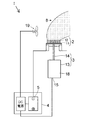
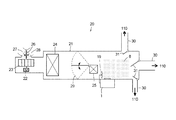
本発明の、金属ナノコロイドや機能性成分をミスト8…として空気中に放出することを可能としたミスト発生装置1は、エアコン、空気清浄機および加湿器などの機器に組み込むことができる。例えば、車に組み込む場合は、図3及び図4に示すように、図3は、乗用車等の車両内に備えられた車両用空調装置の空調ユニットの概略構成図である。
図3において、空調ユニット20は、ケース21の内部に、外付けのブロアモータ22に駆動されるブロアファン23と、ブロアファン23により送風された空気を冷却するエバポレータ24と、エバポレータ24で冷却された空気を再加熱するヒータコア25と、ヒータコア25への配風比を調節するエアミックスドア29等とを備えている。
ブロアファン23の前面には、外気導入口27または内気導入口28からの空気の流入比を制御するインテークドア26が設置されている。
電圧で制御されるブロアモータ22により駆動されるブロアファン23で加圧、送風された送風空気は、エバポレータ24を通過して冷却される。
The
In FIG. 3, the
An
The blown air pressurized and blown by the blower fan 23 driven by the
エアミックスドア29は、設定温度などの空調運転条件に応じて開度すなわち配風比が変化する。エアミックスドア29で分配されてヒータコア25を通過した空気と、ヒータコア25を通過しなかった空気とは、ヒータコア25下流で再び合流して車室内に供給される。送風空気は、エアミックスドア29の開度により加熱量が調整される。
The
また、空調ユニット20は、ヒータコア25下流で再び合流して温度が制御された空調空気がそれぞれ供給されるダクト30と、ダクト30を開閉するベントドア31とを備えている。
In addition, the
図4は、車両用空調装置が搭載されている乗用車を車両斜め上方から見た斜視図である。
図4に示すように、車両のインストルメントパネルの運転席側には車両の中央側および窓側にセンターベント吹出口130およびサイドベント吹出口140が設けられ、助手席側には車両の中央側および窓側にセンターベント吹出口120およびサイドベント吹出口150が設けられ、前席の足元付近にフット吹出口160が設けられている。
空調ユニット20のダクト30内の空調空気は、分岐したダクトを介してそれぞれサイドベント吹出口150、センターベント吹出口120、センターベント吹出口130、サイドベント吹出口140、フット吹出口160から車室内に送風される。
FIG. 4 is a perspective view of a passenger car on which a vehicle air conditioner is mounted as viewed from obliquely above the vehicle.
As shown in FIG. 4, a
The conditioned air in the
また、本発明のミスト発生装置1は、空調ユニット20のヒータコア25の下流とダクト30との間の空調空気の送風経路に設置されており、その空調空気にミストを供給するようになっている。
Moreover, the
なお、本実施の形態では、エバポレータ24に付着している凝縮水を利用して、エバポレータ24の周囲を通過して加湿された空気にミスト発生装置1からミストを供給することによって、乗員の降車時における静電気の除去を行うこともできる。
しかし、エンジンの停止によりブロアファン23は停止して送風は行われなくなるが、ミスト発生装置1に独立した電源を付与することにより、エンジンを切った場合でもミスト発生装置1が独自に駆動させることができるので、ベント吹出口110からのミストが導入された空気は、センターベント吹出口120等から駐車中の車室内に導入することができる。
In this embodiment, the condensed water adhering to the
However, when the engine is stopped, the blower fan 23 is stopped and air blowing is not performed. However, by providing an independent power source to the
このように、従来の空調ユニットでは、加湿された空気がケースの内部に保たれているため、カビなどが生え易い環境にあり、車室内に送風される空気もカビ臭いものであったが、本願実施態様のミスト発生装置1をケース21内に設けることにより、カビ菌の発生を抑制し、また防臭効果もある。
In this way, in the conventional air conditioning unit, since the humidified air is kept inside the case, it is in an environment where mold and the like are prone to grow, and the air blown into the vehicle interior also has a moldy odor, By providing the
また、上記の実施の形態では、ミスト発生装置1は空調ユニット20内のヒータコア25とベントダクト30との間の送風空気の経路に設置されているが、ミスト発生装置1の設置位置は別の位置に設置してもよい。
例えば、ミスト発生装置1は、ベントダクト30の内部、またはベント吹出口120の近傍等に設置することもできる。
Moreover, in said embodiment, although the
For example, the
以上説明したように、本発明に係る静電霧化装置は、先端部12aまで保水した放出ピン部材12が直流電源4の負極5を接続した場合、大気中6の水蒸気との間に放電現象が起き、OHラジカルが発生するが、オゾンは発生しないように構成したので、放出ピン部材12への水溶液の供給量や吸い上げ速度を制御することができ、機能性成分の放出速度または放出量を制御することができる。
また、微粒子径が小さいミストほど、OHラジカルを多く含むので、化学反応による無臭化や抗菌、抗カビ効果に優れている。
As described above, in the electrostatic atomizer according to the present invention, when the
In addition, a mist having a smaller fine particle diameter contains more OH radicals, and therefore has superior bromide-free, antibacterial, and antifungal effects due to chemical reaction.
また、多孔質の保水材11に多孔質の放出ピン部材12を突設して形成され吸水性、保水性および吸上げ特性を有する多孔質成型体2と、多孔質成型体2に負極5が接続され多孔質成型体2を負に帯電させる直流高電圧電源4とを備え、かつ、多孔質成型体2が帯電した負に対する正の対極を備えていないので、多孔質の放出ピン部材12…から自然放電現象が起こり、風を利用してナノサイズのミストを大量に放出させることができる。そして、正の対極を備えていないので、放出するミストにオゾンを全く発生させずに済む。また、機能性成分を効率よく含ませてミスト化することができる。
Also, a porous molded
1 ミスト発生装置
2 多孔質成型体
3 給水手段
4 直流電源
5 負極
6 大気中
8 ミスト
11 保水材
12 放出ピン部材
12a 先端部
13 収容容器
14 供給パイプ
15 水量センサ
18 水溶液
19 ファン
20 空調ユニット
21 ケース
22 ブロアモータ
23 ブロアファン
24 エバポレータ
25 ヒータコア
26 インテークドア
27 外気導入口
28 内気導入口
29 エアミックスドア
30 ダクト
31 ベントドア
120 センターベント吹出口
130 センターベント吹出口
140 サイドベント吹出口
150 サイドベント吹出口
160 フット吹出口
DESCRIPTION OF
Claims (7)
多孔質の保水材に、放出ピン部材を突設して形成された多孔質成型体と、
該多孔質成型体に負極が接続され該多孔質成型体を負に帯電させる直流電源とを備え、
前記給水手段から金属ナノコロイドを配合した水溶液を吸い上げて放出ピン部材から金属ナノコロイドを配合したミストを放出する静電霧化装置であって、
前記放出ピン部材は、その長さが異なる複数本を保水材上に突設して形成したものであることを特徴とする静電霧化装置。 Water supply means for containing an aqueous solution containing metal nanocolloids;
A porous molded body formed by projecting a release pin member on a porous water retention material; and
A negative power source connected to the porous molded body, and a DC power source for negatively charging the porous molded body,
An electrostatic atomizer that sucks up an aqueous solution containing metal nanocolloid from the water supply means and releases a mist containing metal nanocolloid from a discharge pin member,
The discharge atomizing device , wherein the discharge pin member is formed by projecting a plurality of different lengths on a water retaining material .
Priority Applications (1)
| Application Number | Priority Date | Filing Date | Title |
|---|---|---|---|
| JP2009234209A JP5561991B2 (en) | 2009-10-08 | 2009-10-08 | Electrostatic atomizer |
Applications Claiming Priority (1)
| Application Number | Priority Date | Filing Date | Title |
|---|---|---|---|
| JP2009234209A JP5561991B2 (en) | 2009-10-08 | 2009-10-08 | Electrostatic atomizer |
Publications (3)
| Publication Number | Publication Date |
|---|---|
| JP2011078622A JP2011078622A (en) | 2011-04-21 |
| JP2011078622A5 JP2011078622A5 (en) | 2012-11-22 |
| JP5561991B2 true JP5561991B2 (en) | 2014-07-30 |
Family
ID=44073350
Family Applications (1)
| Application Number | Title | Priority Date | Filing Date |
|---|---|---|---|
| JP2009234209A Active JP5561991B2 (en) | 2009-10-08 | 2009-10-08 | Electrostatic atomizer |
Country Status (1)
| Country | Link |
|---|---|
| JP (1) | JP5561991B2 (en) |
Families Citing this family (8)
| Publication number | Priority date | Publication date | Assignee | Title |
|---|---|---|---|---|
| CN102538358A (en) * | 2012-01-31 | 2012-07-04 | 合肥美的荣事达电冰箱有限公司 | Refrigeration equipment |
| JP6348803B2 (en) * | 2013-08-28 | 2018-06-27 | 住友化学株式会社 | Ultrasonic atomizer |
| WO2015049676A1 (en) * | 2013-10-01 | 2015-04-09 | Scentcom Ltd. | System and method for dispensing liquids |
| CN104646214B (en) * | 2013-11-21 | 2019-07-19 | 株式会社铁克诺弗隆帝亚 | Discharge contact pin component, mist generates component and the electrostatic atomization apparatus using it |
| KR101596712B1 (en) | 2015-01-14 | 2016-02-23 | 현대자동차주식회사 | Eco-humidifier for vehicle |
| JP6575162B2 (en) * | 2015-06-16 | 2019-09-18 | 株式会社デンソー | Drying suppression device and program |
| JP6665732B2 (en) * | 2016-08-23 | 2020-03-13 | 株式会社デンソー | Static electricity suppressing device, static electricity suppressing method |
| CN114953934B (en) * | 2022-07-28 | 2022-09-30 | 北京福乐云数据科技有限公司 | Active fog ion chip and electron atomizing device thereof |
Family Cites Families (4)
| Publication number | Priority date | Publication date | Assignee | Title |
|---|---|---|---|---|
| JP2005193082A (en) * | 2003-12-26 | 2005-07-21 | Matsushita Electric Works Ltd | Electrostatic atomizer |
| JP2008212887A (en) * | 2007-03-07 | 2008-09-18 | Techno Frontier:Kk | Electrostatic atomizing device |
| JP4036886B2 (en) * | 2007-04-06 | 2008-01-23 | 松下電工株式会社 | Electrostatic atomizer |
| JP2009202059A (en) * | 2008-02-26 | 2009-09-10 | Panasonic Electric Works Co Ltd | Electrostatic atomizing apparatus |
-
2009
- 2009-10-08 JP JP2009234209A patent/JP5561991B2/en active Active
Also Published As
| Publication number | Publication date |
|---|---|
| JP2011078622A (en) | 2011-04-21 |
Similar Documents
| Publication | Publication Date | Title |
|---|---|---|
| JP5561991B2 (en) | Electrostatic atomizer | |
| JP2008212887A (en) | Electrostatic atomizing device | |
| TW572789B (en) | Air cleaner | |
| JP5149473B2 (en) | Deodorization device | |
| JP2006305321A (en) | Air purifier, and air cleaner and humidifier using the same | |
| KR102162454B1 (en) | Anion release, sterilization and aroma diffuser generating multi functional air cleaner for automotive vehicles | |
| CA2935139C (en) | Apparatus for disinfecting an enclosed space | |
| WO2004110640A1 (en) | Electrostatic atomizing device and humidifier using this | |
| JP4322822B2 (en) | Functional component-containing mist generator | |
| JP2001286546A (en) | Deodorant sprayer | |
| US20110000368A1 (en) | Dynamic electrostatic apparatus for purifying air using electronically charged droplets | |
| TWI693102B (en) | Device for negatively discharging micronized liquid | |
| JP2005270669A (en) | Liquid atomizer and air purifier or deodorizer incorporating the same | |
| EP1689603B1 (en) | A mist-spraying apparatus | |
| US20110000369A1 (en) | Dynamic electrostatic apparatus for purifying air using electronically charged nanodroplets | |
| CN101314151A (en) | Electrostatic atomization apparatus | |
| JP2006212588A (en) | Air cleaning apparatus, air cleaner and humidifier | |
| JP2006097960A (en) | Air purifier, air cleaner, and humidifier | |
| CN212378160U (en) | Air conditioner nanometer water ion generation system and air conditioner | |
| WO2004110642A1 (en) | Electrostatic atomizer with anion ion generating function and air cleaner using same | |
| JP2011062613A (en) | Electrostatic atomizer | |
| JP5153819B2 (en) | Air purifier and equipment equipped with the same | |
| JP3179884U (en) | Electrostatic atomizer | |
| CN102824972B (en) | Release contact pin components and use its electrostatic atomization apparatus | |
| JP2012115798A (en) | Air cleaning device |
Legal Events
| Date | Code | Title | Description |
|---|---|---|---|
| A521 | Request for written amendment filed |
Free format text: JAPANESE INTERMEDIATE CODE: A523 Effective date: 20121005 |
|
| A621 | Written request for application examination |
Free format text: JAPANESE INTERMEDIATE CODE: A621 Effective date: 20121005 |
|
| A977 | Report on retrieval |
Free format text: JAPANESE INTERMEDIATE CODE: A971007 Effective date: 20130625 |
|
| A131 | Notification of reasons for refusal |
Free format text: JAPANESE INTERMEDIATE CODE: A131 Effective date: 20130703 |
|
| A977 | Report on retrieval |
Free format text: JAPANESE INTERMEDIATE CODE: A971007 Effective date: 20130815 |
|
| A521 | Request for written amendment filed |
Free format text: JAPANESE INTERMEDIATE CODE: A523 Effective date: 20130902 |
|
| TRDD | Decision of grant or rejection written | ||
| A01 | Written decision to grant a patent or to grant a registration (utility model) |
Free format text: JAPANESE INTERMEDIATE CODE: A01 Effective date: 20140530 |
|
| A61 | First payment of annual fees (during grant procedure) |
Free format text: JAPANESE INTERMEDIATE CODE: A61 Effective date: 20140610 |
|
| R150 | Certificate of patent or registration of utility model |
Ref document number: 5561991 Country of ref document: JP Free format text: JAPANESE INTERMEDIATE CODE: R150 |
|
| R250 | Receipt of annual fees |
Free format text: JAPANESE INTERMEDIATE CODE: R250 |
|
| R250 | Receipt of annual fees |
Free format text: JAPANESE INTERMEDIATE CODE: R250 |
|
| R250 | Receipt of annual fees |
Free format text: JAPANESE INTERMEDIATE CODE: R250 |
|
| R250 | Receipt of annual fees |
Free format text: JAPANESE INTERMEDIATE CODE: R250 |
|
| R250 | Receipt of annual fees |
Free format text: JAPANESE INTERMEDIATE CODE: R250 |
|
| R250 | Receipt of annual fees |
Free format text: JAPANESE INTERMEDIATE CODE: R250 |
|
| R250 | Receipt of annual fees |
Free format text: JAPANESE INTERMEDIATE CODE: R250 |
|
| S531 | Written request for registration of change of domicile |
Free format text: JAPANESE INTERMEDIATE CODE: R313532 |
|
| R350 | Written notification of registration of transfer |
Free format text: JAPANESE INTERMEDIATE CODE: R350 |
|
| R250 | Receipt of annual fees |
Free format text: JAPANESE INTERMEDIATE CODE: R250 |