JP5558695B2 - Nonvolatile semiconductor memory device - Google Patents
Nonvolatile semiconductor memory device Download PDFInfo
- Publication number
- JP5558695B2 JP5558695B2 JP2008294786A JP2008294786A JP5558695B2 JP 5558695 B2 JP5558695 B2 JP 5558695B2 JP 2008294786 A JP2008294786 A JP 2008294786A JP 2008294786 A JP2008294786 A JP 2008294786A JP 5558695 B2 JP5558695 B2 JP 5558695B2
- Authority
- JP
- Japan
- Prior art keywords
- insulating film
- gate electrode
- film
- disposed
- memory device
- Prior art date
- Legal status (The legal status is an assumption and is not a legal conclusion. Google has not performed a legal analysis and makes no representation as to the accuracy of the status listed.)
- Active
Links
- 239000004065 semiconductor Substances 0.000 title claims description 138
- 229910052751 metal Inorganic materials 0.000 claims description 71
- 239000002184 metal Substances 0.000 claims description 71
- 239000000758 substrate Substances 0.000 claims description 38
- 150000004767 nitrides Chemical class 0.000 claims description 36
- 238000009792 diffusion process Methods 0.000 claims description 34
- 229910021332 silicide Inorganic materials 0.000 claims description 26
- FVBUAEGBCNSCDD-UHFFFAOYSA-N silicide(4-) Chemical compound [Si-4] FVBUAEGBCNSCDD-UHFFFAOYSA-N 0.000 claims description 24
- XUIMIQQOPSSXEZ-UHFFFAOYSA-N Silicon Chemical compound [Si] XUIMIQQOPSSXEZ-UHFFFAOYSA-N 0.000 claims description 22
- 229910052710 silicon Inorganic materials 0.000 claims description 21
- 239000010703 silicon Substances 0.000 claims description 21
- 239000000463 material Substances 0.000 claims description 17
- 239000012535 impurity Substances 0.000 claims description 14
- 238000003860 storage Methods 0.000 claims description 14
- 239000004020 conductor Substances 0.000 claims description 8
- 150000002736 metal compounds Chemical class 0.000 claims description 3
- 239000000126 substance Substances 0.000 claims description 2
- 229910021420 polycrystalline silicon Inorganic materials 0.000 description 52
- 229920005591 polysilicon Polymers 0.000 description 52
- VYPSYNLAJGMNEJ-UHFFFAOYSA-N Silicium dioxide Chemical compound O=[Si]=O VYPSYNLAJGMNEJ-UHFFFAOYSA-N 0.000 description 41
- 229910052814 silicon oxide Inorganic materials 0.000 description 41
- 238000004519 manufacturing process Methods 0.000 description 35
- 229910052581 Si3N4 Inorganic materials 0.000 description 34
- HQVNEWCFYHHQES-UHFFFAOYSA-N silicon nitride Chemical compound N12[Si]34N5[Si]62N3[Si]51N64 HQVNEWCFYHHQES-UHFFFAOYSA-N 0.000 description 34
- 238000000034 method Methods 0.000 description 20
- 230000006870 function Effects 0.000 description 14
- 238000005530 etching Methods 0.000 description 12
- 238000001020 plasma etching Methods 0.000 description 11
- 238000000206 photolithography Methods 0.000 description 10
- 230000000903 blocking effect Effects 0.000 description 9
- 238000005229 chemical vapour deposition Methods 0.000 description 8
- 238000002955 isolation Methods 0.000 description 7
- 230000000694 effects Effects 0.000 description 6
- 239000011229 interlayer Substances 0.000 description 5
- 229910021417 amorphous silicon Inorganic materials 0.000 description 4
- 229910052769 Ytterbium Inorganic materials 0.000 description 3
- 238000010438 heat treatment Methods 0.000 description 3
- 239000010410 layer Substances 0.000 description 3
- 229910052697 platinum Inorganic materials 0.000 description 3
- BOTDANWDWHJENH-UHFFFAOYSA-N Tetraethyl orthosilicate Chemical compound CCO[Si](OCC)(OCC)OCC BOTDANWDWHJENH-UHFFFAOYSA-N 0.000 description 2
- 229910052782 aluminium Inorganic materials 0.000 description 2
- 229910052790 beryllium Inorganic materials 0.000 description 2
- 229910052737 gold Inorganic materials 0.000 description 2
- 229910052735 hafnium Inorganic materials 0.000 description 2
- 229910052738 indium Inorganic materials 0.000 description 2
- 238000005468 ion implantation Methods 0.000 description 2
- 229910052741 iridium Inorganic materials 0.000 description 2
- 229910052750 molybdenum Inorganic materials 0.000 description 2
- 229910052759 nickel Inorganic materials 0.000 description 2
- 230000003647 oxidation Effects 0.000 description 2
- 238000007254 oxidation reaction Methods 0.000 description 2
- 229910052763 palladium Inorganic materials 0.000 description 2
- 229910052702 rhenium Inorganic materials 0.000 description 2
- 229910052703 rhodium Inorganic materials 0.000 description 2
- 229910052714 tellurium Inorganic materials 0.000 description 2
- 229910052719 titanium Inorganic materials 0.000 description 2
- 229910052721 tungsten Inorganic materials 0.000 description 2
- 229910052727 yttrium Inorganic materials 0.000 description 2
- 229910052725 zinc Inorganic materials 0.000 description 2
- 229910052726 zirconium Inorganic materials 0.000 description 2
- -1 Metal Oxide Nitride Chemical class 0.000 description 1
- 229910004200 TaSiN Inorganic materials 0.000 description 1
- ATJFFYVFTNAWJD-UHFFFAOYSA-N Tin Chemical compound [Sn] ATJFFYVFTNAWJD-UHFFFAOYSA-N 0.000 description 1
- 238000007599 discharging Methods 0.000 description 1
- 238000009413 insulation Methods 0.000 description 1
- 239000012212 insulator Substances 0.000 description 1
- 229910044991 metal oxide Inorganic materials 0.000 description 1
- 150000002739 metals Chemical class 0.000 description 1
- 238000012986 modification Methods 0.000 description 1
- 230000004048 modification Effects 0.000 description 1
Images


Classifications
-
- H—ELECTRICITY
- H10—SEMICONDUCTOR DEVICES; ELECTRIC SOLID-STATE DEVICES NOT OTHERWISE PROVIDED FOR
- H10B—ELECTRONIC MEMORY DEVICES
- H10B43/00—EEPROM devices comprising charge-trapping gate insulators
- H10B43/30—EEPROM devices comprising charge-trapping gate insulators characterised by the memory core region
-
- H—ELECTRICITY
- H01—ELECTRIC ELEMENTS
- H01L—SEMICONDUCTOR DEVICES NOT COVERED BY CLASS H10
- H01L29/00—Semiconductor devices adapted for rectifying, amplifying, oscillating or switching, or capacitors or resistors with at least one potential-jump barrier or surface barrier, e.g. PN junction depletion layer or carrier concentration layer; Details of semiconductor bodies or of electrodes thereof ; Multistep manufacturing processes therefor
- H01L29/40—Electrodes ; Multistep manufacturing processes therefor
- H01L29/401—Multistep manufacturing processes
- H01L29/4011—Multistep manufacturing processes for data storage electrodes
- H01L29/40117—Multistep manufacturing processes for data storage electrodes the electrodes comprising a charge-trapping insulator
-
- H—ELECTRICITY
- H10—SEMICONDUCTOR DEVICES; ELECTRIC SOLID-STATE DEVICES NOT OTHERWISE PROVIDED FOR
- H10B—ELECTRONIC MEMORY DEVICES
- H10B43/00—EEPROM devices comprising charge-trapping gate insulators
- H10B43/20—EEPROM devices comprising charge-trapping gate insulators characterised by three-dimensional arrangements, e.g. with cells on different height levels
- H10B43/23—EEPROM devices comprising charge-trapping gate insulators characterised by three-dimensional arrangements, e.g. with cells on different height levels with source and drain on different levels, e.g. with sloping channels
- H10B43/27—EEPROM devices comprising charge-trapping gate insulators characterised by three-dimensional arrangements, e.g. with cells on different height levels with source and drain on different levels, e.g. with sloping channels the channels comprising vertical portions, e.g. U-shaped channels
-
- H—ELECTRICITY
- H01—ELECTRIC ELEMENTS
- H01L—SEMICONDUCTOR DEVICES NOT COVERED BY CLASS H10
- H01L27/00—Devices consisting of a plurality of semiconductor or other solid-state components formed in or on a common substrate
- H01L27/02—Devices consisting of a plurality of semiconductor or other solid-state components formed in or on a common substrate including semiconductor components specially adapted for rectifying, oscillating, amplifying or switching and having at least one potential-jump barrier or surface barrier; including integrated passive circuit elements with at least one potential-jump barrier or surface barrier
- H01L27/04—Devices consisting of a plurality of semiconductor or other solid-state components formed in or on a common substrate including semiconductor components specially adapted for rectifying, oscillating, amplifying or switching and having at least one potential-jump barrier or surface barrier; including integrated passive circuit elements with at least one potential-jump barrier or surface barrier the substrate being a semiconductor body
- H01L27/06—Devices consisting of a plurality of semiconductor or other solid-state components formed in or on a common substrate including semiconductor components specially adapted for rectifying, oscillating, amplifying or switching and having at least one potential-jump barrier or surface barrier; including integrated passive circuit elements with at least one potential-jump barrier or surface barrier the substrate being a semiconductor body including a plurality of individual components in a non-repetitive configuration
- H01L27/0688—Integrated circuits having a three-dimensional layout
Description
本発明は、不揮発性半導体記憶装置に関する。 The present invention relates to a nonvolatile semiconductor memory device.
不揮発性半導体記憶装置のメモリセルは半導体基板上にゲート絶縁膜、制御ゲート電極が積層されたトランジスタ構造をなしている。このメモリセルの書き込み/消去は、制御ゲート電極と基板間に電圧を印加することでトンネル電流を流し、電荷蓄積膜中の電荷の有無で閾値電圧を制御することによって、データを記憶させる。メモリセルの構造には、例えば、MONOS(Metal Oxide Nitride Oxide Silicon)構造、スタックゲート構造等がある。 A memory cell of a nonvolatile semiconductor memory device has a transistor structure in which a gate insulating film and a control gate electrode are stacked on a semiconductor substrate. In the writing / erasing of the memory cell, data is stored by applying a voltage between the control gate electrode and the substrate to cause a tunnel current to flow and controlling the threshold voltage depending on the presence or absence of charges in the charge storage film. Examples of the structure of the memory cell include a MONOS (Metal Oxide Nitride Oxide Silicon) structure and a stacked gate structure.
MONOS構造等は、チャージトラップ型とも呼ばれ、例えば、ゲート絶縁膜として電荷を選択的に通過させるトンネル絶縁膜(シリコン酸化膜)、電荷蓄積絶縁膜(シリコン窒化膜)、及び電荷蓄積絶縁膜と制御ゲート電極間の電流を阻止するブロッキング絶縁膜(シリコン酸化膜)が順次積層されており、シリコン窒化膜中に局在するトラップサイトへの電荷トラップによって閾値を変化させる。 The MONOS structure or the like is also called a charge trap type. For example, a tunnel insulating film (silicon oxide film), a charge storage insulating film (silicon nitride film), and a charge storage insulating film that selectively pass charges as a gate insulating film Blocking insulating films (silicon oxide films) for blocking current between the control gate electrodes are sequentially stacked, and the threshold value is changed by trapping electric charges at trap sites localized in the silicon nitride film.
スタックゲート構造は、浮遊ゲート型とも呼ばれ、例えば、トンネル絶縁膜(シリコン酸化膜)、浮遊ゲート電極(ポリシリコン膜)、電極間絶縁膜(ONO膜)、制御ゲート電極が順次積層されている。書き込み/消去は、制御ゲート電極と半導体基板間に高電圧を印加することでFN(Fow1er-Nordheim)トンネル電流を流し、トンネル絶縁膜と浮遊ゲート電極間で電荷の出し入れをすることによって行われる。つまり、浮遊ゲート電極内の電荷の有無で閾値電圧を制御することによって、データを記憶させる。 The stack gate structure is also called a floating gate type. For example, a tunnel insulating film (silicon oxide film), a floating gate electrode (polysilicon film), an interelectrode insulating film (ONO film), and a control gate electrode are sequentially stacked. . Writing / erasing is performed by applying a high voltage between the control gate electrode and the semiconductor substrate to cause a FN (Fow1er-Nordheim) tunnel current to flow, and charging / discharging between the tunnel insulating film and the floating gate electrode. That is, data is stored by controlling the threshold voltage based on the presence or absence of charge in the floating gate electrode.
これらのどちらのメモリセルも、メモリセルに隣接する選択トランジスタによって選択される。選択トランジスタは、電荷を蓄積し続ける必要はなく、例えば、ゲート絶縁膜(シリコン酸化膜)とその上に制御ゲート電極(ポリシリコン膜)が順次積層されている。 Both of these memory cells are selected by a selection transistor adjacent to the memory cell. The selection transistor does not need to continue accumulating charges. For example, a gate insulating film (silicon oxide film) and a control gate electrode (polysilicon film) are sequentially stacked thereon.
メモリセルトランジスタ及び選択トランジスタは、それぞれの閾値電圧が許容範囲に収められることは重要である。スタックゲート構造において、例えば、メモリセルは、浮遊ゲート電極と、浮遊ゲート電極上に配置されるゲート間絶縁膜と、ゲート間絶縁膜上に配置される制御ゲート電極とを有し、選択トランジスタは、下側ゲート電極と、下側ゲート電極上に配置され、開口部を有するゲート間絶縁膜と、少なくとも開口部に形成され、金属原子の拡散をブロックする機能を有するブロック膜と、第2ゲート間絶縁膜上に配置され、ブロック膜を介して下側ゲート電極に電気的に接続される上側ゲート電極とを有し、メモリセルの制御ゲート電極及び選択トランジスタの上側ゲート電極がフルシリサイド化される構造が開示されている(例えば、特許文献1参照。)。 It is important that the threshold voltage of each of the memory cell transistor and the select transistor is within an allowable range. In the stacked gate structure, for example, a memory cell includes a floating gate electrode, an intergate insulating film disposed on the floating gate electrode, and a control gate electrode disposed on the intergate insulating film, and the selection transistor is A lower gate electrode; an intergate insulating film disposed on the lower gate electrode and having an opening; a blocking film formed at least in the opening and having a function of blocking diffusion of metal atoms; and a second gate And an upper gate electrode electrically connected to the lower gate electrode through the block film, and the control gate electrode of the memory cell and the upper gate electrode of the select transistor are fully silicided. (For example, refer to Patent Document 1).
開示されたスタックゲート構造は、選択トランジスタの下側ゲート電極が、シリサイド化されないポリシリコンを残し、メモリセルの制御ゲート電極が、フルシリサイドとされる構成とし、両トランジスタの制御ゲート電極が異なる仕事関数を有することが可能である。これらのゲート電極はゲート間絶縁膜を共通に有し、一方の選択トランジスタはゲート間絶縁膜に開口を有する構成であることを利用している。 The disclosed stacked gate structure has a structure in which the lower gate electrode of the selection transistor is left as non-silicided polysilicon, the control gate electrode of the memory cell is fully silicided, and the control gate electrodes of both transistors are different in work. It is possible to have a function. These gate electrodes have an inter-gate insulating film in common, and one of the select transistors utilizes the configuration having an opening in the inter-gate insulating film.
しかしながら、チャージトラップ型は、ゲート間絶縁膜を配する構造にはなっていないので、開示されたスタックゲート構造の技術をそのまま適用することが難しい。また、開示された技術では、選択トランジスタの下側ゲート電極にポリシリコンを残して、閾値電圧を制御するという選択に限定され、その他の構成を取ることが難しいという問題がある。
本発明は、互いに異なる仕事関数のゲート電極を有するメモリセルトランジスタ及び選択トランジスタを構成可能なチャージトラップ型の不揮発性半導体記憶装置を提供する。 The present invention provides a charge trap type nonvolatile semiconductor memory device capable of forming a memory cell transistor and a select transistor having gate electrodes with different work functions.
本発明の一態様の不揮発性半導体記憶装置は、表面に、互いに離間して設けられたソースまたはドレインとなる拡散領域を有する半導体基板と、前記拡散領域の間の前記半導体基板の表面に、電荷蓄積絶縁膜を有する第1の絶縁膜が配設され、前記第1の絶縁膜の上に接して、不純物がドープされたシリコン及び金属系導電性材料のグループから選択される少なくとも1つの材料が配置された第1のゲート電極を備えたメモリセルトランジスタと、前記拡散領域の間の前記半導体基板の表面に、第2の絶縁膜が配設され、前記第2の絶縁膜の上に接して、前記不純物がドープされたシリコン及び前記金属系導電性材料のグループから選択される少なくとも1つの材料が配置された第2のゲート電極を備えた選択トランジスタとを具備し、前記第1のゲート電極に配置され前記第1の絶縁膜の上に接する材料と、前記第2のゲート電極に配置され前記第2の絶縁膜の上に接する材料とは異なり、チャージトラップ型であることを特徴とする。
A nonvolatile semiconductor memory device according to one embodiment of the present invention includes a semiconductor substrate having a diffusion region serving as a source or a drain provided at a distance from each other on the surface, and a charge on the surface of the semiconductor substrate between the diffusion regions. A first insulating film having a storage insulating film is disposed, and at least one material selected from the group of silicon doped with impurities and a metal-based conductive material is in contact with the first insulating film. A second insulating film is disposed on the surface of the semiconductor substrate between the memory cell transistor having the first gate electrode and the diffusion region, and is in contact with the second insulating film. A selection transistor comprising a second gate electrode on which at least one material selected from the group consisting of silicon doped with the impurity and the metal-based conductive material is disposed, The material disposed on one gate electrode and in contact with the first insulating film is different from the material disposed on the second gate electrode and in contact with the second insulating film, and is a charge trap type. It is characterized by.
また、本発明の別態様の不揮発性半導体記憶装置は、表面に、互いに離間して設けられたソースまたはドレインとなる拡散領域を有する半導体基板と、前記拡散領域の間の前記半導体基板の表面に、電荷蓄積絶縁膜を有する第1の絶縁膜が配設され、前記第1の絶縁膜の上に接して、第1の幅を有するシリサイドが配置された第1のゲート電極を備えたメモリセルトランジスタと、前記拡散領域の間の前記半導体基板の表面に、第2の絶縁膜が配設され、前記第2の絶縁膜の上に接して、順に、第1の幅より大きい第2の幅を有する不純物がドープされたシリコン及び前記シリサイドが配置された第2のゲート電極を備えた選択トランジスタと、を具備し、チャージトラップ型であることを特徴とする。
In addition, a nonvolatile semiconductor memory device according to another aspect of the present invention includes a semiconductor substrate having a diffusion region serving as a source or a drain provided at a distance from each other on the surface, and a surface of the semiconductor substrate between the diffusion regions. A memory cell having a first gate electrode in which a first insulating film having a charge storage insulating film is disposed and in which a silicide having a first width is disposed in contact with the first insulating film; A second insulating film is disposed on the surface of the semiconductor substrate between the transistor and the diffusion region, and is in contact with the second insulating film and sequentially has a second width larger than the first width. And a selection transistor including a second gate electrode in which the silicide is disposed and silicon doped with an impurity having an impurity, and is a charge trap type .
本発明によれば、互いに異なる仕事関数のゲート電極を有するメモリセルトランジスタ及び選択トランジスタを構成可能なチャージトラップ型の不揮発性半導体記憶装置を提供する。 According to the present invention, there is provided a charge trap type nonvolatile semiconductor memory device capable of constituting a memory cell transistor and a select transistor having gate electrodes having different work functions.
以下、本発明の実施例について、図面を参照しながら説明する。各図では、同一の構成要素には同一の符号を付す。 Embodiments of the present invention will be described below with reference to the drawings. In each figure, the same components are denoted by the same reference numerals.
本発明の実施例1に係る不揮発性半導体記憶装置及びその製造方法について、図1乃至図9を参照しながら説明する。図1は不揮発性半導体記憶装置の構造を模式的に示す断面図である。図2乃至図9は、不揮発性半導体記憶装置の製造方法を工程順に模式的に示す構造断面図である。図2乃至図9のそれぞれの(a)及び(b)は、図1(b)の2点鎖線で囲んだ領域、及び図1(c)の2点鎖線で囲んだ領域に、それぞれ対応している。なお、半導体基板の表面において、半導体基板から離れる方向を上または上方向として説明する。 A nonvolatile semiconductor memory device and a manufacturing method thereof according to Embodiment 1 of the present invention will be described with reference to FIGS. FIG. 1 is a cross-sectional view schematically showing the structure of a nonvolatile semiconductor memory device. 2 to 9 are structural cross-sectional views schematically showing the method of manufacturing the nonvolatile semiconductor memory device in the order of steps. (A) and (b) in FIGS. 2 to 9 correspond to the region surrounded by the two-dot chain line in FIG. 1 (b) and the region surrounded by the two-dot chain line in FIG. 1 (c), respectively. ing. Note that, in the surface of the semiconductor substrate, the direction away from the semiconductor substrate will be described as upward or upward.
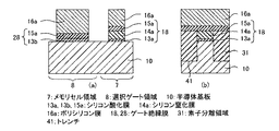
図1に示すように、NAND型の不揮発性半導体記憶装置1は、表面に、互いに離間して設けられたソースまたはドレインとする拡散領域21を有する半導体基板10と、拡散領域21の間の半導体基板10の表面に、順に、トンネル絶縁膜13、電荷蓄積絶縁膜14、及びブロッキング絶縁膜15を有する第1の絶縁膜であるゲート絶縁膜18が配設され、ゲート絶縁膜18の上に接して、第1の幅である幅L1を有するシリサイド膜17aが配置された第1のゲート電極であるゲート電極19を備えたメモリセル領域7にあるメモリセルトランジスタ5と、拡散領域21の間の半導体基板10の表面に、第2の絶縁膜であるゲート絶縁膜28が配設され、ゲート絶縁膜28の上に接して、順に、第1の幅より大きい第2の幅である幅L2を有する不純物ドープのシリコンされたポリシリコン膜16a及びシリサイド膜17aが配置された第2のゲート電極であるゲート電極29を備えた選択ゲート領域8にある選択トランジスタ6とを具備している。
As shown in FIG. 1, a NAND-type nonvolatile semiconductor memory device 1 includes a
また、図1(a)に示すように、不揮発性半導体記憶装置1は、複数の素子領域11(網掛け表示)がストライプ状に平行に、図面左右に伸長して設けられている。素子領域11内には、ソースまたはドレインとなる拡散領域21が互いに離間して設けられている。また、素子領域11間には、例えば、シリコン酸化膜からなる素子分離領域31が設けられている。
As shown in FIG. 1A, the non-volatile semiconductor memory device 1 is provided with a plurality of element regions 11 (shaded display) extending in parallel to the stripe shape and extending to the left and right of the drawing. In the element region 11, diffusion regions 21 serving as a source or a drain are provided apart from each other. Further, an
メモリセルトランジスタ5のゲート電極19は、素子領域11に直交するように、ストライプ状に平行に、図面上下に伸長して設けられている。メモリセルは個々にメモリセルトランジスタ5に対応し、メモリセル領域7に格子状に配設されている。
The
選択トランジスタ6のゲート電極29は、ゲート電極19に平行に、メモリセル領域7を挟むように両側に、1対の選択トランジスタ6が配置されている。つまり、各メモリセルトランジスタ5のソースとドレイン、すなわち拡散領域21は、隣接するものが共通に接続されて、メモリブロックが形成され、メモリブロックの両端に選択トランジスタ6が設けられている。ゲート電極29は、2本ずつ選択ゲート領域8に配設されている。ここでは2本ずつ図示しているが、選択できればゲート電極29を有する選択ゲートは1本でもよい。
A pair of
図1(b)及び(c)に示すように、半導体基板10は、例えば、p型シリコン基板であり、拡散領域21は、n型の不純物、例えばAsが注入されている。拡散領域21は、対向する拡散領域21側に、それぞれ張り出したエクステンション領域が設けられていることが多い。隣接する拡散領域21間の一部は、チャネル領域(図示略)として機能する。なお、半導体基板10は、p型ウェルが設けられた基板構造とすること、絶縁層の上にp型シリコンを有するSOI(Silicon on Insulator)基板とすることが可能であり、また、半導体基板10及び拡散領域21は、それぞれ逆の導電型で構成することが可能である。
As shown in FIGS. 1B and 1C, the
また、ゲート絶縁膜18、28及びゲート電極19、29は、間を、例えば、シリコン絶縁膜からなる層間絶縁膜33で埋め込まれている。なお、図示を省略するが、ゲート絶縁膜18、28及びゲート電極19、29の側壁部及び上部は、シリコン酸化膜またはシリコン窒化膜またはシリコン酸窒化膜の少なくとも一つからなる絶縁膜で被われている。
The
メモリセル領域7では、隣接する拡散領域21間のチャネル領域の上部に、トンネル絶縁膜13、電荷蓄積絶縁膜14、及びブロッキング絶縁膜15に、それぞれ、対応するシリコン酸化膜13a、シリコン窒化膜14a、及びシリコン酸化膜15aからなるゲート絶縁膜18が設けられている。なお、トンネル絶縁膜13は、シリコン酸化膜、シリコン酸窒化膜、並びに、シリコン酸化膜及びシリコン窒化膜を積層した膜のいずれかで構成することが可能である。
In the
メモリセルトランジスタ5のゲート電極19は、ゲート絶縁膜18の最上層のブロッキング絶縁膜15に接して、幅L1のシリサイド膜17aが配設されている。シリサイド膜17aは、例えば、Niを主成分とする。ゲート電極19の幅L1が、例えば、製造プロセスの最小寸法で形成される。なお、シリサイド膜17aは、その他に、Co、Pt、Yb、W等の内の少なくとも1つの元素を主成分とすることが可能である。
The
一方、選択ゲート領域8では、隣接する拡散領域21間のチャネル領域の上部に、シリコン酸化膜13b及びシリコン酸化膜15aからなるゲート絶縁膜28が設けられている。
On the other hand, in the
選択トランジスタ6のゲート電極29は、シリコン酸化膜15aに接して、幅L1のポリシリコン膜16aが配置され、ポリシリコン膜16aのシリコン酸化膜15aとは反対側に接して、幅L1のシリサイド膜17aが配置されている。つまり、ポリシリコン膜16aとシリサイド膜17aとの境界は、ゲート電極29の半導体基板10の表面からの高さ方向の中間にある。ゲート電極29は、必要とするトランジスタの駆動能力を発揮するために、チャネル長がゲート電極19より大きく設定され、同時に、幅L2が幅L1より大きく、例えば、2倍乃至それ以上大きく形成されている。
The
ポリシリコン膜16aは、不純物、例えばPが導入されて、抵抗が低く形成されている。なお、ポリシリコン膜16aの不純物は他のn型またはp型の不純物から適宜選択することが可能である。
The
次に、不揮発性半導体記憶装置1の製造方法について説明する。製造工程の説明において、不揮発性半導体記憶装置1を構成する材料または配置等が補足される。 Next, a method for manufacturing the nonvolatile semiconductor memory device 1 will be described. In the description of the manufacturing process, the material or arrangement of the nonvolatile semiconductor memory device 1 is supplemented.
図2に示すように、半導体基板10の表面に、シリコン酸化膜13aが熱酸化法により形成され、シリコン酸化膜13aの上に、シリコン窒化膜14aがCVD(Chemical Vapor Deposition)法により形成される。図示を省略するが、その後、シリコン窒化膜14aの上に、例えば、フォトリソグラフィ法によりパターニングしたアモルファスシリコンを形成し、このアモルファスシリコンをマスクとして、RIE(Reactive Ion Etching)法によりエッチングを行う。
As shown in FIG. 2, a
図3に示すように、メモリセル領域7(図3(a)の右側)で、シリコン酸化膜13a及びシリコン窒化膜14aが残り、選択ゲート領域8(図3(a)の左側)で、シリコン酸化膜13a及びシリコン窒化膜14aがエッチングされる。
As shown in FIG. 3, the
図4に示すように、半導体基板10の表面に、シリコン酸化膜13bが熱酸化法により形成される。図示を省略するが、その後、シリコン酸化膜13b及びシリコン窒化膜14aの上に、例えば、フォトリソグラフィ法によりパターニングしたアモルファスシリコンを形成し、このアモルファスシリコンをマスクとして、RIE法によりエッチングを行う。素子分離領域33(図4(b)の左右両端側)となる領域にトレンチ41を形成し、次に、例えば、このトレンチ41にCVD法によりシリコン酸化膜を埋め込み、平坦化またはエッチングを行う。
As shown in FIG. 4, a
図5に示すように、トレンチ41に素子分離領域31が形成され、表面にシリコン酸化膜13b、シリコン窒化膜14a、及び素子分離領域31の上面が露出する。
As shown in FIG. 5, the
図6に示すように、シリコン酸化膜13b、シリコン窒化膜14a、及び素子分離領域33の表面に、シリコン酸化膜15aをCVD法により形成する。その後、シリコン酸化膜15aの表面に、Pがドープされたポリシリコン膜16aを形成する。図示を省略するが、その後、ポリシリコン膜16aの上に、フォトリソグラフィ法によりパターニングしたシリコン窒化膜を形成し、このシリコン窒化膜をマスクとして、RIE法によりエッチングを行う。
As shown in FIG. 6, a
図7に示すように、ゲート絶縁膜18及びゲート電極19となる領域に、ほぼ幅L1となるシリコン酸化膜13a、シリコン窒化膜14a、シリコン酸化膜15a、及びポリシリコン膜16aを形成し、ゲート絶縁膜28及びゲート電極29となる領域に、ほぼ幅L2となるシリコン酸化膜13b、シリコン酸化膜15a、及びポリシリコン膜16aを形成する。図示を省略するが、その後、形成された積層膜の側壁部及び上部に、シリコン酸化膜またはシリコン窒化膜またはシリコン酸窒化膜の少なくとも一方からなる絶縁膜を形成し、半導体基板10の表面に、イオン注入を行って、拡散領域21を形成する。なお、側壁の絶縁膜を形成する前に、イオン注入を行って、エクステンション領域を形成することは可能である。
As shown in FIG. 7, a
図8に示すように、ゲート絶縁膜18、28及びゲート電極19、29となる領域の間に、TEOS(Tetraethoxysilane)系のシリコン酸化膜からなる層間絶縁膜33が埋め込まれ、次に、ポリシリコン膜16aの上面が露出するように、CMP法により平坦化して、平坦化された層間絶縁膜33及びポリシリコン膜16aの上に、例えばNiからなるシリサイド形成用の金属膜35aがCVD法により堆積される。
As shown in FIG. 8, an
図9に示すように、加熱処理を行って、ゲート絶縁膜18の上に、ポリシリコン膜16aと金属膜35aとが反応して、全てシリサイド化されたシリサイド膜17aを形成し、同時に、ゲート絶縁膜28の上に、ポリシリコン膜16aの上部のみがシリサイド化されたシリサイド膜17aを形成する。つまり、ゲート絶縁膜18の上のゲート電極19は、幅L1のシリサイド膜17aで構成され、ゲート絶縁膜28の上のゲート電極29は、幅L2のポリシリコン膜16a及びシリサイド膜17aで構成される。
As shown in FIG. 9, the heat treatment is performed to react the
ポリシリコン膜16aと金属膜35aとが加熱処理によって反応するシリサイド化は、幅の狭い幅L1のポリシリコン膜16aにおいて、幅の広い幅L2のポリシリコン膜16aより早く進行する、いわゆる細線効果を利用して行われる。幅L1と幅L2は、幅L1のポリシリコン膜16aで全てシリサイド化され、一方、幅L2のポリシリコン膜16aで、ゲート絶縁膜28の上に、ポリシリコン膜16aがシリサイド化されずに安定的に残るように決められる。シリサイド化の速度差は、加熱温度、金属膜35aの種類や膜厚、ポリシリコン膜16aの膜厚、不純物濃度や結晶性等により変化するが、本実施例においては、幅L2を幅L1の約3倍とした。なお、金属膜35aはNiの他、上述の元素とすることが可能である。
The silicidation in which the
上述したように、不揮発性半導体記憶装置1は、メモリセル領域7のメモリセルトランジスタ5のゲート電極19を幅L1とし、選択ゲート領域8の選択トランジスタ6のゲート電極29を幅L1より大きな幅L2として、ゲート電極19がゲート絶縁膜18に接して全てシリサイド膜17aで構成され、ゲート電極29がゲート絶縁膜28に接してポリシリコン膜16a及びその上のシリサイド膜17aで構成されている。
As described above, in the nonvolatile semiconductor memory device 1, the
その結果、チャージトラップ型の不揮発性半導体記憶装置1は、異なる仕事関数のゲート電極19、29を有するメモリセルトランジスタ5及び選択トランジスタ6を構成可能である。異なる仕事関数を有するゲート電極19、29を得たことにより、不揮発性半導体記憶装置1は、メモリセルトランジスタ5及び選択トランジスタ6の閾値電圧をより適当な値に設定することが可能となる。
As a result, the charge trap type nonvolatile semiconductor memory device 1 can constitute the
本発明の実施例2に係る不揮発性半導体記憶装置について、図10乃至図13を参照しながら説明する。図10乃至図13は、半導体装置の製造方法を工程順に模式的に示す構造断面図であり、図10は、図11乃至図13に示す工程を経て得られる構造断面図である。実施例1の不揮発性半導体記憶装置とは、メモリセルトランジスタのゲート電極が、ゲート絶縁膜の上に金属窒化膜を配設した構成であることが異なる。なお、実施例1と同一構成部分には同一の符号を付して、その説明は省略する。 A non-volatile semiconductor memory device according to Example 2 of the present invention will be described with reference to FIGS. FIG. 10 to FIG. 13 are structural cross-sectional views schematically showing the semiconductor device manufacturing method in the order of steps, and FIG. 10 is a structural cross-sectional view obtained through the steps shown in FIG. 11 to FIG. The nonvolatile semiconductor memory device of Example 1 is different from the nonvolatile semiconductor memory device in that the gate electrode of the memory cell transistor has a configuration in which a metal nitride film is disposed on the gate insulating film. In addition, the same code | symbol is attached | subjected to the same component as Example 1, and the description is abbreviate | omitted.
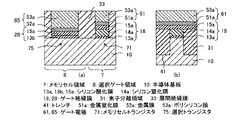
図10に示すように、本実施例の不揮発性半導体記憶装置は、実施例1の不揮発性半導体記憶装置1に対して、メモリセル領域7のメモリセルトランジスタ71のゲート電極61の構成、及び選択ゲート領域8の選択ゲートトランジスタ72のゲート電極62の構成が異なる。すなわち、ゲート電極61は、ゲート絶縁膜18に接して、例えば、TaNからなる金属窒化膜51aが形成され、金属窒化膜51aの上にポリシリコン膜53aが形成されており、一方、ゲート電極62は、ゲート絶縁膜28に接して、ポリシリコン膜53aが形成されている。その他の構成は、実施例1の不揮発性半導体記憶装置1と同様であり、ポリシリコン膜53aは、実施例1のポリシリコン膜16aと同様である。なお、金属窒化膜51aは、TaNの他に、TiN、WN、TaSiN等が可能である。
As shown in FIG. 10, the nonvolatile semiconductor memory device of this example is different from the nonvolatile semiconductor memory device 1 of Example 1 in the configuration and selection of the
次に、本実施例の不揮発性半導体記憶装置の製造方法について説明する。実施例1の不揮発性半導体記憶装置の製造方法と同様に、図6に示す工程の前まで進めて、次に、図11に示すように、シリコン酸化膜13b、シリコン窒化膜14a、及び素子分離領域33の表面に、シリコン酸化膜15aをCVD法により形成する。その後、シリコン酸化膜15aの表面に、CVD法で金属窒化膜51aを形成する。図示を省略するが、その後、金属窒化膜51aの上に、フォトリソグラフィ法によりパターニングしたシリコン窒化膜を形成し、このシリコン窒化膜をマスクとして、RIE法によりエッチングを行う。
Next, a method for manufacturing the nonvolatile semiconductor memory device of this example will be described. Similar to the method of manufacturing the nonvolatile semiconductor memory device of the first embodiment, the process proceeds to the step shown in FIG. 6, and then, as shown in FIG. 11, the
図12に示すように、メモリセル領域7(図12(a)の右側)で、金属窒化膜51aが残り、選択ゲート領域8(図12(a)の左側)で、金属窒化膜51aがエッチングされる。
As shown in FIG. 12, the
図13に示すように、シリコン酸化膜15a及び金属窒化膜51aの表面に、Pがドープされたポリシリコン膜53aを形成する。図示を省略するが、その後、ポリシリコン膜53aの上に、フォトリソグラフィ法によりパターニングしたシリコン窒化膜を形成し、このシリコン窒化膜をマスクとして、RIE法によりエッチングを行う。
As shown in FIG. 13, a
図10に示すように、実施例1の図7示す工程から、図8に示す工程の一部と同様にして、層間絶縁膜33を形成し、メモリセル領域7に上述の構成のゲート電極61、及び選択ゲート領域8に上述の構成のゲート電極62が得られる。
As shown in FIG. 10, the
上述したように、本実施例の不揮発性半導体記憶装置は、メモリセルトランジスタ71のゲート電極61がゲート絶縁膜18に接して金属窒化膜51a及びその上のポリシリコン膜53aで構成され、選択トランジスタ72のゲート電極62がゲート絶縁膜28に接してポリシリコン膜53aで構成されている。
As described above, in the nonvolatile semiconductor memory device of this embodiment, the
その結果、本実施例の不揮発性半導体記憶装置は、異なる仕事関数のゲート電極61、62を有するメモリセルトランジスタ71及び選択トランジスタ72を構成可能であり、実施例1の不揮発性半導体記憶装置1と同様な効果を有している。その他に、本実施例の不揮発性半導体記憶装置のゲート電極の幅は、実施例1の不揮発性半導体記憶装置1のゲート電極の幅より制約が少なくなる。
As a result, the nonvolatile semiconductor memory device according to the present embodiment can configure the
本発明の実施例3に係る不揮発性半導体記憶装置について、図14乃至図16を参照しながら説明する。図14乃至図16は、半導体装置の製造方法を工程順に模式的に示す構造断面図であり、図14は、図15及び図16に示す工程を経て得られる構造断面図である。実施例1の不揮発性半導体記憶装置とは、選択トランジスタのゲート電極が、ゲート絶縁膜の上に金属窒化膜を配設した構成であることが異なる。なお、実施例1及び2と同一構成部分には同一の符号を付して、その説明は省略する。 A non-volatile semiconductor memory device according to Example 3 of the present invention will be described with reference to FIGS. 14 to 16 are structural cross-sectional views schematically showing the method of manufacturing a semiconductor device in the order of steps, and FIG. 14 is a structural cross-sectional view obtained through the steps shown in FIGS. 15 and 16. The nonvolatile semiconductor memory device of Example 1 is different in that the gate electrode of the selection transistor has a configuration in which a metal nitride film is disposed on the gate insulating film. In addition, the same code | symbol is attached | subjected to the same component as Example 1 and 2, and the description is abbreviate | omitted.
図14に示すように、本実施例の不揮発性半導体記憶装置は、実施例1の不揮発性半導体記憶装置1に対して、メモリセル領域7のメモリセルトランジスタ73のゲート電極63の構成、及び選択ゲート領域8の選択トランジスタ74のゲート電極64の構成が異なる。すなわち、ゲート電極63は、ゲート絶縁膜18に接して、ポリシリコン膜53aが形成されており、一方、ゲート電極64は、ゲート絶縁膜28に接して、例えば、TaNからなる金属窒化膜51aが形成され、金属窒化膜51aの上にポリシリコン膜53aが形成されている。その他の構成は、実施例1の不揮発性半導体記憶装置1と同様である。
As shown in FIG. 14, the nonvolatile semiconductor memory device of this example is different from the nonvolatile semiconductor memory device 1 of Example 1 in the configuration and selection of the
次に、本実施例の不揮発性半導体記憶装置の製造方法について説明する。実施例2の不揮発性半導体記憶装置の製造方法と同様に、図11に示す工程まで進める。図示を省略するが、その後、金属窒化膜51aの上に、フォトリソグラフィ法によりパターニングしたシリコン窒化膜を形成し、このシリコン窒化膜をマスクとして、RIE法によりエッチングを行う。
Next, a method for manufacturing the nonvolatile semiconductor memory device of this example will be described. Similar to the method of manufacturing the nonvolatile semiconductor memory device according to the second embodiment, the process proceeds to the process shown in FIG. Although illustration is omitted, a silicon nitride film patterned by photolithography is then formed on the
図15に示すように、メモリセル領域7(図15(a)の右側)で、金属窒化膜51aがエッチングされ、選択ゲート領域8(図15(a)の左側)で、金属窒化膜51aが残される。
As shown in FIG. 15, the
図16に示すように、シリコン酸化膜15a及び金属窒化膜51aの表面に、Pがドープされたポリシリコン膜53aを形成する。図示を省略するが、その後、ポリシリコン膜53aの上に、フォトリソグラフィ法によりパターニングしたシリコン窒化膜を形成し、このシリコン窒化膜をマスクとして、RIE法によりエッチングを行う。
As shown in FIG. 16, a
図14に示すように、実施例2の図10示す工程と同様にして、上述のメモリセル領域7に上述の構成のゲート電極63、及び選択ゲート領域8に上述の構成のゲート電極64が得られる。
As shown in FIG. 14, the
上述したように、本実施例の不揮発性半導体記憶装置は、メモリセルトランジスタ73のゲート電極63がゲート絶縁膜18に接してポリシリコン膜53aで構成され、選択トランジスタ74のゲート電極64がゲート絶縁膜28に接して金属窒化膜51a及びその上のポリシリコン膜53aで構成されている。
As described above, in the nonvolatile semiconductor memory device of this embodiment, the
その結果、本実施例の不揮発性半導体記憶装置は、異なる仕事関数のゲート電極63、64を有するメモリセルトランジスタ73及び選択トランジスタ74を構成可能であり、実施例1の不揮発性半導体記憶装置1と同様な効果を有している。また、本実施例の不揮発性半導体記憶装置のゲート電極63、64の仕事関数は、実施例2の不揮発性半導体記憶装置のゲート電極61、62の仕事関数と逆の関係にあるが、実施例2の不揮発性半導体記憶装置が有する効果と同様な効果を有している。
As a result, the nonvolatile semiconductor memory device according to the present embodiment can constitute the
本発明の実施例4に係る不揮発性半導体記憶装置について、図17乃至図20を参照しながら説明する。図17乃至図20は、半導体装置の製造方法を工程順に模式的に示す構造断面図であり、図17は、図18乃至図20に示す工程を経て得られる構造断面図である。実施例1の不揮発性半導体記憶装置とは、メモリセルトランジスタのゲート電極が、ゲート絶縁膜の上に金属窒化膜を配置し、選択トランジスタのゲート電極が、ゲート絶縁膜の上に金属膜を配設した構成であることが異なる。なお、実施例1乃至3と同一構成部分には同一の符号を付して、その説明は省略する。 A non-volatile semiconductor memory device according to Example 4 of the present invention will be described with reference to FIGS. FIG. 17 to FIG. 20 are structural cross-sectional views schematically showing the semiconductor device manufacturing method in the order of steps, and FIG. 17 is a structural cross-sectional view obtained through the steps shown in FIG. 18 to FIG. In the nonvolatile semiconductor memory device of Example 1, the gate electrode of the memory cell transistor has a metal nitride film disposed on the gate insulating film, and the gate electrode of the select transistor has the metal film disposed on the gate insulating film. The configuration is different. In addition, the same code | symbol is attached | subjected to the same component as Example 1 thru | or 3, and the description is abbreviate | omitted.
図17に示すように、本実施例の不揮発性半導体記憶装置は、実施例2の不揮発性半導体記憶装置に対して、選択ゲート領域8の選択トランジスタ75のゲート電極65の構成が異なる。すなわち、ゲート電極65は、ゲート絶縁膜28に接して、例えば、Ruからなる金属膜52aが形成され、金属膜52aの上にポリシリコン膜53aが形成されている。その他の構成は、実施例2の不揮発性半導体記憶装置と同様である。なお、金属膜52aは、Ruの他に、Au、Pt、Co、Be、Ni、Rh、Pd、Te、Re、Mo、Al、Hf、Ta、Mn、Zn、Zr、In、Bi、W、Ir、Er、La、Ti、Y、Yb等が可能である。
As shown in FIG. 17, the nonvolatile semiconductor memory device of this example differs from the nonvolatile semiconductor memory device of Example 2 in the configuration of the
次に、本実施例の不揮発性半導体記憶装置の製造方法について説明する。実施例2の不揮発性半導体記憶装置の製造方法と同様に、図12に示す工程まで進める。次に、図18に示すように、シリコン酸化膜15a、及び金属窒化膜51aの表面に、金属膜52aをCVD法により形成する。図示を省略するが、その後、金属膜52aの上に、フォトリソグラフィ法によりパターニングしたシリコン窒化膜を形成し、このシリコン窒化膜をマスクとして、RIE法によりエッチングを行う。
Next, a method for manufacturing the nonvolatile semiconductor memory device of this example will be described. Similar to the manufacturing method of the nonvolatile semiconductor memory device of Example 2, the process proceeds to the process shown in FIG. Next, as shown in FIG. 18, a
図19に示すように、メモリセル領域7(図19(a)の右側)で、金属膜52aがエッチングされ、選択ゲート領域8(図19(a)の左側)で、金属膜52aが残される。
As shown in FIG. 19, the
図20に示すように、金属窒化膜51a及び金属膜52aの表面に、Pがドープされたポリシリコン膜53aを形成する。図示を省略するが、その後、ポリシリコン膜53aの上に、フォトリソグラフィ法によりパターニングしたシリコン窒化膜を形成し、このシリコン窒化膜をマスクとして、RIE法によりエッチングを行う。
As shown in FIG. 20, a
図17に示すように、実施例2の図10示す工程と同様にして、メモリセル領域7に上述の構成のゲート電極61、及び選択ゲート領域8に上述の構成のゲート電極65が得られる。
As shown in FIG. 17, the
上述したように、本実施例の不揮発性半導体記憶装置は、メモリセルトランジスタ71のゲート電極61がゲート絶縁膜18に接して金属窒化膜51a及びその上のポリシリコン膜53aで構成され、選択ゲート領域8のゲート電極65がゲート絶縁膜28に接して金属膜52a及びその上のポリシリコン膜53aで構成されている。
As described above, in the nonvolatile semiconductor memory device of this embodiment, the
その結果、本実施例の不揮発性半導体記憶装置は、異なる仕事関数のゲート電極61、65を有するメモリセルトランジスタ71及び選択トランジスタ75を構成可能であり、実施例1乃至3の不揮発性半導体記憶装置と同様な効果を有している。また、本実施例の不揮発性半導体記憶装置のゲート電極61、65の仕事関数は、金属窒化膜51a及び金属膜52aの中から適宜組み合わせることが可能となり、より適するものを選択することが可能となる。
As a result, the nonvolatile semiconductor memory device of the present embodiment can constitute the
本発明の実施例5に係る不揮発性半導体記憶装置について、図21及び図22を参照しながら説明する。図21及び図22は、半導体装置の製造方法を工程順に模式的に示す構造断面図であり、図21は、図22に示す工程を経て得られる構造断面図である。実施例4の不揮発性半導体記憶装置とは、メモリセルトランジスタのゲート電極が、ゲート絶縁膜の上に金属窒化膜及び金属膜を配設した構成であることが異なる。なお、実施例1乃至4と同一構成部分には同一の符号を付して、その説明は省略する。 A non-volatile semiconductor memory device according to Example 5 of the present invention will be described with reference to FIGS. 21 and 22 are structural cross-sectional views schematically showing the semiconductor device manufacturing method in the order of steps, and FIG. 21 is a structural cross-sectional view obtained through the steps shown in FIG. The nonvolatile semiconductor memory device of Example 4 is different from the nonvolatile semiconductor memory device in that the gate electrode of the memory cell transistor has a configuration in which a metal nitride film and a metal film are disposed on the gate insulating film. In addition, the same code | symbol is attached | subjected to the same component as Examples 1-4, and the description is abbreviate | omitted.
図21に示すように、本実施例の不揮発性半導体記憶装置は、実施例4の不揮発性半導体記憶装置に対して、メモリセル領域7のメモリセルトランジスタ76のゲート電極66の構成が異なる。すなわち、ゲート電極66は、ゲート絶縁膜18に接して、金属窒化膜51aが形成され、金属窒化膜51aの上に金属膜52aが形成され、金属膜52aの上にポリシリコン膜53aが形成されている。その他の構成は、実施例4の不揮発性半導体記憶装置と同様である。
As shown in FIG. 21, the nonvolatile semiconductor memory device of this example differs from the nonvolatile semiconductor memory device of Example 4 in the configuration of the
次に、本実施例の不揮発性半導体記憶装置の製造方法について説明する。実施例4の不揮発性半導体記憶装置の製造方法と同様に、図18に示す工程まで進める。次に、図22に示すように、金属膜52aの表面に、Pがドープされたポリシリコン膜53aを形成する。図示を省略するが、その後、ポリシリコン膜53aの上に、フォトリソグラフィ法によりパターニングしたシリコン窒化膜を形成し、このシリコン窒化膜をマスクとして、RIE法によりエッチングを行う。
Next, a method for manufacturing the nonvolatile semiconductor memory device of this example will be described. Similar to the method of manufacturing the nonvolatile semiconductor memory device of Example 4, the process proceeds to the process shown in FIG. Next, as shown in FIG. 22, a
図21に示すように、実施例4の図17示す工程と同様にして、メモリセル領域7に上述の構成のゲート電極66、及び選択ゲート領域8に上述の構成のゲート電極65が得られる。
As shown in FIG. 21, the
上述したように、本実施例の不揮発性半導体記憶装置は、メモリセルトランジスタ76のゲート電極66がゲート絶縁膜18に接して、順に、金属窒化膜51a、金属膜52a、及びポリシリコン膜53aで構成され、選択ゲートトランジスタ75のゲート電極65がゲート絶縁膜28に接して金属膜52a及びその上のポリシリコン膜53aで構成されている。
As described above, in the nonvolatile semiconductor memory device of this embodiment, the
その結果、本実施例の不揮発性半導体記憶装置は、異なる仕事関数のゲート電極65、66を有するメモリセルトランジスタ76及び選択トランジスタ75を構成可能であり、実施例4の不揮発性半導体記憶装置と同様な効果を有している。また、本実施例の不揮発性半導体記憶装置は、実施例4の不揮発性半導体記憶装置と比較して、金属膜52aをエッチングする工程が不要となるので、製造工程の短縮が可能である。
As a result, the nonvolatile semiconductor memory device of the present embodiment can constitute the
本発明は、上述した実施例に限定されるものではなく、本発明の要旨を逸脱しない範囲内で、種々、変形して実施することができる。 The present invention is not limited to the above-described embodiments, and various modifications can be made without departing from the spirit of the present invention.
例えば、実施例では、ゲート絶縁膜は、シリコン酸化膜、シリコン窒化膜、シリコン酸窒化膜である例を示したが、誘電率のより高い、例えば、Hf等を含む酸化膜、Hf等を含むシリコン酸化膜、Hf等を含む酸窒化膜、及びHf等を含むシリコン酸窒化膜等のいわゆるhigh-k膜とすることは可能である。 For example, in the embodiment, the gate insulating film is a silicon oxide film, a silicon nitride film, or a silicon oxynitride film. However, the gate insulating film has a higher dielectric constant, for example, an oxide film containing Hf or the like, or Hf or the like. A so-called high-k film such as a silicon oxide film, an oxynitride film including Hf, and a silicon oxynitride film including Hf can be used.
また、実施例では、不揮発性半導体記憶装置は、NAND型である例を示したが、他の論理、例えば、AND型を構成するメモリセルトランジスタ及び選択トランジスタに同様に適用可能である。 In the embodiments, an example in which the nonvolatile semiconductor memory device is a NAND type has been described. However, the present invention can be similarly applied to other logic, for example, a memory cell transistor and a selection transistor that constitute an AND type.
また、実施例では、メモリセルトランジスタ及び選択トランジスタのゲート絶縁膜に接するゲート電極の例として、ポリシリコン膜、シリサイド膜、金属窒化膜、及び金属膜の内の2つの組合せの幾つかを示したが、実施例で示した組合せ以外の別の組合せとすることは可能である。 In the embodiment, some examples of two combinations of a polysilicon film, a silicide film, a metal nitride film, and a metal film are shown as examples of the gate electrode in contact with the gate insulating film of the memory cell transistor and the selection transistor. However, other combinations than the combinations shown in the embodiments are possible.
また、実施例では、ゲート電極の材料として、金属単体、シリサイド(珪化物)、窒化物等の金属系導電性材料の例を示したが、その他に、実施例で示した元素を1つ以上含む金属単体もしくは金属化合物、または、これらの珪化物、ホウ化物、窒化物、もしくは炭化物であることは可能である。 In the embodiments, examples of metal conductive materials such as simple metals, silicides (silicides), and nitrides are shown as materials for the gate electrode. In addition, one or more of the elements shown in the embodiments are used. It can be a simple metal or metal compound, or a silicide, boride, nitride, or carbide thereof.
その他、以下の付記に記載されるような構成が考えられる。
(付記1) 表面に、互いに離間して設けられたソースまたはドレインとなる拡散領域を有する半導体基板と、前記拡散領域の間の前記半導体基板の表面に、電荷蓄積絶縁膜を有する第1の絶縁膜が配設され、前記第1の絶縁膜の上に接して、第1の幅を有するシリサイドが配置された第1のゲート電極を備えたメモリセルトランジスタと、前記拡散領域の間の前記半導体基板の表面に、第2の絶縁膜が配設され、前記第2の絶縁膜の上に接して、順に、第1の幅より大きい第2の幅を有する不純物がドープされたシリコン及び前記シリサイドが配置された第2のゲート電極を備えた選択トランジスタとを具備している不揮発性半導体記憶装置。
In addition, configurations as described in the following supplementary notes are conceivable.
(Supplementary Note 1) A semiconductor substrate having a diffusion region serving as a source or drain provided on the surface and serving as a source or drain, and a first insulation having a charge storage insulating film on the surface of the semiconductor substrate between the diffusion regions A memory cell transistor having a first gate electrode on which a silicide having a first width is disposed in contact with the first insulating film, and the semiconductor between the diffusion region A second insulating film is disposed on the surface of the substrate, and is in contact with the second insulating film and is sequentially doped with an impurity having a second width larger than the first width and the silicide. A non-volatile semiconductor memory device comprising: a selection transistor including a second gate electrode on which is disposed.
(付記2) 前記金属系導電性材料は、Au、Pt、Co、Be、Ni、Rh、Pd、Te、Re、Mo、Al、Hf、Ta、Mn、Zn、Zr、In、Bi、Ru、W、Ir、Er、La、Ti、Y、Ybのうちから選ばれる1つ以上の元素を含む金属単体もしくは金属化合物、または、これらの珪化物、ホウ化物、窒化物、もしくは炭化物である付記1に記載の不揮発性半導体記憶装置。 (Supplementary Note 2) The metal-based conductive material includes Au, Pt, Co, Be, Ni, Rh, Pd, Te, Re, Mo, Al, Hf, Ta, Mn, Zn, Zr, In, Bi, Ru, Supplementary note 1 which is a metal simple substance or metal compound containing one or more elements selected from W, Ir, Er, La, Ti, Y, and Yb, or a silicide, boride, nitride, or carbide thereof. The non-volatile semiconductor memory device described in 1.
(付記3) 前記第1の絶縁膜は、前記半導体基板の表面側から、順に、トンネル絶縁膜、電荷蓄積絶縁膜、及びブロッキング絶縁膜を有する付記1に記載の不揮発性半導体記憶装置。 (Additional remark 3) The said 1st insulating film is a non-volatile semiconductor memory device of Additional remark 1 which has a tunnel insulating film, a charge storage insulating film, and a blocking insulating film in order from the surface side of the said semiconductor substrate.
(付記4) 前記トンネル絶縁膜は、シリコン酸化膜、シリコン酸窒化膜、並びに、シリコン酸化膜及びシリコン窒化膜を積層した膜のいずれかである付記1に記載の不揮発性半導体記憶装置。 (Supplementary Note 4) The nonvolatile semiconductor memory device according to supplementary note 1, wherein the tunnel insulating film is any one of a silicon oxide film, a silicon oxynitride film, and a film in which a silicon oxide film and a silicon nitride film are stacked.
(付記5) 前記半導体基板は、前記拡散領域の表面とは反対側の内部に、絶縁層を有する付記1に記載の不揮発性半導体記憶装置。 (Additional remark 5) The said semiconductor substrate is a non-volatile semiconductor memory device of Additional remark 1 which has an insulating layer inside the opposite side to the surface of the said diffusion area | region.
1 不揮発性半導体記憶装置
5、71、73、76 メモリセルトランジスタ
6、72、74、75 選択トランジスタ
7 メモリセル領域
8 選択ゲート領域
10 半導体基板
11 素子領域
13 トンネル絶縁層
13a、13b、15a シリコン酸化膜
14 電荷蓄積絶縁膜
14a シリコン窒化膜
15 ブロッキング絶縁膜
16a、53a ポリシリコン膜
17a シリサイド膜
18、28 ゲート絶縁膜
19、29、61、62、63、64、65、66 ゲート電極
21 拡散領域
31 素子分離領域
33 層間絶縁膜
35a、52a 金属膜
41 トレンチ
51a 金属窒化膜
L1、L2 幅
DESCRIPTION OF SYMBOLS 1 Nonvolatile
Claims (4)
前記拡散領域の間の前記半導体基板の表面に、電荷蓄積絶縁膜を有する第1の絶縁膜が配設され、前記第1の絶縁膜の上に接して、不純物がドープされたシリコン及び金属系導電性材料のグループから選択される少なくとも1つの材料が配置された第1のゲート電極を備えたメモリセルトランジスタと、
前記拡散領域の間の前記半導体基板の表面に、第2の絶縁膜が配設され、前記第2の絶縁膜の上に接して、前記不純物がドープされたシリコン及び前記金属系導電性材料のグループから選択される少なくとも1つの材料が配置された第2のゲート電極を備えた選択トランジスタとを具備し、
前記第1のゲート電極に配置され前記第1の絶縁膜の上に接する材料と、前記第2のゲート電極に配置され前記第2の絶縁膜の上に接する材料とは異なり、
前記第1のゲート電極は、前記第1の絶縁膜の上に接して設けられた金属窒化物を含む多層構造であることを特徴とするチャージトラップ型の不揮発性半導体記憶装置。 On the surface, a semiconductor substrate having a diffusion region to be a source or drain provided apart from each other,
A first insulating film having a charge storage insulating film is disposed on the surface of the semiconductor substrate between the diffusion regions, and a silicon and metal system doped with impurities in contact with the first insulating film A memory cell transistor comprising a first gate electrode on which at least one material selected from the group of conductive materials is disposed;
A second insulating film is disposed on the surface of the semiconductor substrate between the diffusion regions, and the impurity-doped silicon and the metal-based conductive material are in contact with the second insulating film. A selection transistor comprising a second gate electrode on which at least one material selected from the group is disposed,
The material disposed on the first gate electrode and in contact with the first insulating film is different from the material disposed on the second gate electrode and in contact with the second insulating film.
The charge trap type nonvolatile semiconductor memory device , wherein the first gate electrode has a multilayer structure including a metal nitride provided on and in contact with the first insulating film .
前記拡散領域の間の前記半導体基板の表面に、電荷蓄積絶縁膜を有する第1の絶縁膜が配設され、前記第1の絶縁膜の上に接して、不純物がドープされたシリコン及び金属系導電性材料のグループから選択される少なくとも1つの材料が配置された第1のゲート電極を備えたメモリセルトランジスタと、 A first insulating film having a charge storage insulating film is disposed on the surface of the semiconductor substrate between the diffusion regions, and a silicon and metal system doped with impurities in contact with the first insulating film A memory cell transistor comprising a first gate electrode on which at least one material selected from the group of conductive materials is disposed;
前記拡散領域の間の前記半導体基板の表面に、第2の絶縁膜が配設され、前記第2の絶縁膜の上に接して、前記不純物がドープされたシリコン及び前記金属系導電性材料のグループから選択される少なくとも1つの材料が配置された第2のゲート電極を備えた選択トランジスタとを具備し、A second insulating film is disposed on the surface of the semiconductor substrate between the diffusion regions, and the impurity-doped silicon and the metal-based conductive material are in contact with the second insulating film. A selection transistor comprising a second gate electrode on which at least one material selected from the group is disposed,
前記第1のゲート電極に配置され前記第1の絶縁膜の上に接する材料と、前記第2のゲート電極に配置され前記第2の絶縁膜の上に接する材料とは異なり、 The material disposed on the first gate electrode and in contact with the first insulating film is different from the material disposed on the second gate electrode and in contact with the second insulating film.
前記第1のゲート電極に配置され、前記第1の絶縁膜の上に接する材料は、不純物がドープされたシリコンであり、 The material disposed on the first gate electrode and in contact with the first insulating film is silicon doped with impurities,
前記第2のゲート電極に配置され、前記第2の絶縁膜の上に接する材料は、金属窒化物であることを特徴とするチャージトラップ型の不揮発性半導体記憶装置。 A charge trap type nonvolatile semiconductor memory device, wherein the material disposed on the second gate electrode and in contact with the second insulating film is a metal nitride.
前記拡散領域の間の前記半導体基板の表面に、電荷蓄積絶縁膜を有する第1の絶縁膜が配設され、前記第1の絶縁膜の上に接して、第1の幅を有するシリサイドが配置された第1のゲート電極を備えたメモリセルトランジスタと、A first insulating film having a charge storage insulating film is disposed on the surface of the semiconductor substrate between the diffusion regions, and a silicide having a first width is disposed on and in contact with the first insulating film. A memory cell transistor having a first gate electrode formed;
前記拡散領域の間の前記半導体基板の表面に、第2の絶縁膜が配設され、前記第2の絶縁膜の上に接して、順に、第1の幅より大きい第2の幅を有する不純物がドープされたシリコン及び前記シリサイドが配置された第2のゲート電極を備えた選択トランジスタと、 A second insulating film is disposed on the surface of the semiconductor substrate between the diffusion regions, and is in contact with the second insulating film and has an impurity having a second width larger than the first width in order. A selection transistor comprising silicon doped with and a second gate electrode on which the silicide is disposed;
を具備していることを特徴とするチャージトラップ型の不揮発性半導体記憶装置。A charge trap type nonvolatile semiconductor memory device.
Priority Applications (4)
| Application Number | Priority Date | Filing Date | Title |
|---|---|---|---|
| JP2008294786A JP5558695B2 (en) | 2008-11-18 | 2008-11-18 | Nonvolatile semiconductor memory device |
| US12/618,119 US8134203B2 (en) | 2008-11-18 | 2009-11-13 | Nonvolatile semiconductor memory device |
| US13/364,588 US8614477B2 (en) | 2008-11-18 | 2012-02-02 | Nonvolatile semiconductor memory device |
| US13/364,602 US8575684B2 (en) | 2008-11-18 | 2012-02-02 | Nonvolatile semiconductor memory device |
Applications Claiming Priority (1)
| Application Number | Priority Date | Filing Date | Title |
|---|---|---|---|
| JP2008294786A JP5558695B2 (en) | 2008-11-18 | 2008-11-18 | Nonvolatile semiconductor memory device |
Publications (3)
| Publication Number | Publication Date |
|---|---|
| JP2010123684A JP2010123684A (en) | 2010-06-03 |
| JP2010123684A5 JP2010123684A5 (en) | 2012-01-12 |
| JP5558695B2 true JP5558695B2 (en) | 2014-07-23 |
Family
ID=42171295
Family Applications (1)
| Application Number | Title | Priority Date | Filing Date |
|---|---|---|---|
| JP2008294786A Active JP5558695B2 (en) | 2008-11-18 | 2008-11-18 | Nonvolatile semiconductor memory device |
Country Status (2)
| Country | Link |
|---|---|
| US (3) | US8134203B2 (en) |
| JP (1) | JP5558695B2 (en) |
Families Citing this family (10)
| Publication number | Priority date | Publication date | Assignee | Title |
|---|---|---|---|---|
| KR101137929B1 (en) * | 2010-05-31 | 2012-05-09 | 에스케이하이닉스 주식회사 | Nonvolatile memory device and method for manufacturing the same |
| JP5549411B2 (en) * | 2010-06-18 | 2014-07-16 | 富士通セミコンダクター株式会社 | Semiconductor device manufacturing method, semiconductor memory manufacturing method, and semiconductor device |
| JP5702227B2 (en) | 2011-05-27 | 2015-04-15 | 東京エレクトロン株式会社 | Selection transistor, method for producing selection transistor, memory device, and method for manufacturing memory device |
| KR20130004784A (en) * | 2011-07-04 | 2013-01-14 | 삼성전자주식회사 | Non-volatile memory device having resistance changeable element and method of forming the same |
| JP6800015B2 (en) * | 2014-01-21 | 2020-12-16 | アプライド マテリアルズ インコーポレイテッドApplied Materials,Incorporated | Dielectric metal stack for 3D flash memory applications |
| JP6250506B2 (en) | 2014-09-16 | 2017-12-20 | 東芝メモリ株式会社 | Integrated circuit device and manufacturing method thereof |
| US9793289B2 (en) | 2015-06-08 | 2017-10-17 | Toshiba Memory Corporation | Non-volatile memory device |
| JP6696865B2 (en) * | 2016-08-31 | 2020-05-20 | ルネサスエレクトロニクス株式会社 | Semiconductor device and manufacturing method thereof |
| CN111384060B (en) * | 2018-12-27 | 2023-11-03 | 爱思开海力士有限公司 | Nonvolatile memory device and method of manufacturing the same |
| KR20200126686A (en) * | 2019-04-30 | 2020-11-09 | 에스케이하이닉스 주식회사 | Manufacturing method of semiconductor device |
Family Cites Families (18)
| Publication number | Priority date | Publication date | Assignee | Title |
|---|---|---|---|---|
| JPS55156371A (en) * | 1979-05-24 | 1980-12-05 | Toshiba Corp | Non-volatile semiconductor memory device |
| US5838041A (en) * | 1995-10-02 | 1998-11-17 | Kabushiki Kaisha Toshiba | Nonvolatile semiconductor memory device having memory cell transistor provided with offset region acting as a charge carrier injecting region |
| JP2000286349A (en) | 1999-03-31 | 2000-10-13 | Sony Corp | Semiconductor device and manufacture thereof |
| JP4346228B2 (en) * | 2000-09-21 | 2009-10-21 | 株式会社東芝 | Nonvolatile semiconductor memory device and manufacturing method thereof |
| US6512263B1 (en) * | 2000-09-22 | 2003-01-28 | Sandisk Corporation | Non-volatile memory cell array having discontinuous source and drain diffusions contacted by continuous bit line conductors and methods of forming |
| JP3947041B2 (en) * | 2001-05-28 | 2007-07-18 | 株式会社東芝 | Semiconductor device and manufacturing method thereof |
| US6925007B2 (en) * | 2001-10-31 | 2005-08-02 | Sandisk Corporation | Multi-state non-volatile integrated circuit memory systems that employ dielectric storage elements |
| US6897522B2 (en) * | 2001-10-31 | 2005-05-24 | Sandisk Corporation | Multi-state non-volatile integrated circuit memory systems that employ dielectric storage elements |
| JP2004039866A (en) | 2002-07-03 | 2004-02-05 | Toshiba Corp | Semiconductor device and its manufacturing method |
| JP2005044844A (en) * | 2003-07-23 | 2005-02-17 | Toshiba Corp | Nonvolatile semiconductor memory device and its manufacturing method |
| JP4041076B2 (en) * | 2004-02-27 | 2008-01-30 | 株式会社東芝 | Data storage system |
| US7829938B2 (en) * | 2005-07-14 | 2010-11-09 | Micron Technology, Inc. | High density NAND non-volatile memory device |
| TWI260769B (en) * | 2005-08-23 | 2006-08-21 | Ememory Technology Inc | Non-volatile memory and operating method thereof |
| JP4965878B2 (en) * | 2006-03-24 | 2012-07-04 | 株式会社東芝 | Nonvolatile semiconductor memory device |
| JP5128172B2 (en) * | 2006-04-28 | 2013-01-23 | 株式会社半導体エネルギー研究所 | Method for manufacturing semiconductor device |
| JP2008159614A (en) | 2006-12-20 | 2008-07-10 | Toshiba Corp | Nonvolatile semiconductor memory |
| US7846817B2 (en) * | 2007-03-26 | 2010-12-07 | Semiconductor Energy Laboratory Co., Ltd. | Method for manufacturing semiconductor device |
| US8089114B2 (en) * | 2007-11-08 | 2012-01-03 | Samsung Electronics Co., Ltd. | Non-volatile memory devices including blocking and interface patterns between charge storage patterns and control electrodes and related methods |
-
2008
- 2008-11-18 JP JP2008294786A patent/JP5558695B2/en active Active
-
2009
- 2009-11-13 US US12/618,119 patent/US8134203B2/en active Active
-
2012
- 2012-02-02 US US13/364,588 patent/US8614477B2/en active Active
- 2012-02-02 US US13/364,602 patent/US8575684B2/en active Active
Also Published As
| Publication number | Publication date |
|---|---|
| US8134203B2 (en) | 2012-03-13 |
| US8575684B2 (en) | 2013-11-05 |
| US8614477B2 (en) | 2013-12-24 |
| US20120146128A1 (en) | 2012-06-14 |
| US20100123184A1 (en) | 2010-05-20 |
| US20120139031A1 (en) | 2012-06-07 |
| JP2010123684A (en) | 2010-06-03 |
Similar Documents
| Publication | Publication Date | Title |
|---|---|---|
| JP5558695B2 (en) | Nonvolatile semiconductor memory device | |
| US9768185B2 (en) | Non-volatile semiconductor memory device and manufacturing method thereof | |
| JP6026913B2 (en) | Manufacturing method of semiconductor device | |
| JP5498011B2 (en) | Nonvolatile semiconductor memory device | |
| US9349743B2 (en) | Method of manufacturing semiconductor device | |
| JP5221065B2 (en) | Nonvolatile semiconductor memory device | |
| JP5210675B2 (en) | Nonvolatile semiconductor memory device and manufacturing method thereof | |
| US9673208B2 (en) | Method of forming memory array and logic devices | |
| EP2846348A1 (en) | Semiconductor device and method of manufacturing the same | |
| JP2009212218A (en) | Semiconductor storage device and method for manufacturing the same | |
| CN106024795B (en) | Semiconductor device and method for manufacturing the same | |
| JP2013045837A (en) | Nonvolatile semiconductor storage device and manufacturing method of the same | |
| JP2022532474A (en) | Manufacturing method of 3D horizontal NOR type memory array | |
| WO2016088196A1 (en) | Method for producing semiconductor device and semiconductor device | |
| JP2011029576A (en) | Nonvolatile semiconductor memory device and manufacturing method thereof | |
| US7986001B2 (en) | Semiconductor memory device and method of manufacturing the same | |
| US20160079265A1 (en) | Nonvolatile semiconductor memory device and method of manufacturing the same | |
| JP2008135715A (en) | Nonvolatile memory element and manufacturing method therefor | |
| JP5319092B2 (en) | Semiconductor device and manufacturing method thereof | |
| JP5937172B2 (en) | Semiconductor device and manufacturing method of semiconductor device | |
| JP2010135561A (en) | Nonvolatile semiconductor storage device | |
| US7166512B2 (en) | Method of fabricating non-volatile memory | |
| JP4599421B2 (en) | Semiconductor device and manufacturing method thereof | |
| JP2010182713A (en) | Nonvolatile semiconductor memory device, and method of manufacturing the same | |
| JP5297556B2 (en) | Nonvolatile semiconductor memory device |
Legal Events
| Date | Code | Title | Description |
|---|---|---|---|
| A521 | Request for written amendment filed |
Free format text: JAPANESE INTERMEDIATE CODE: A523 Effective date: 20111117 |
|
| A621 | Written request for application examination |
Free format text: JAPANESE INTERMEDIATE CODE: A621 Effective date: 20111117 |
|
| RD02 | Notification of acceptance of power of attorney |
Free format text: JAPANESE INTERMEDIATE CODE: A7422 Effective date: 20111125 |
|
| RD04 | Notification of resignation of power of attorney |
Free format text: JAPANESE INTERMEDIATE CODE: A7424 Effective date: 20111205 |
|
| A977 | Report on retrieval |
Free format text: JAPANESE INTERMEDIATE CODE: A971007 Effective date: 20130731 |
|
| A131 | Notification of reasons for refusal |
Free format text: JAPANESE INTERMEDIATE CODE: A131 Effective date: 20130802 |
|
| A521 | Request for written amendment filed |
Free format text: JAPANESE INTERMEDIATE CODE: A523 Effective date: 20130930 |
|
| A521 | Request for written amendment filed |
Free format text: JAPANESE INTERMEDIATE CODE: A523 Effective date: 20131001 |
|
| A131 | Notification of reasons for refusal |
Free format text: JAPANESE INTERMEDIATE CODE: A131 Effective date: 20140110 |
|
| A521 | Request for written amendment filed |
Free format text: JAPANESE INTERMEDIATE CODE: A523 Effective date: 20140310 |
|
| TRDD | Decision of grant or rejection written | ||
| A01 | Written decision to grant a patent or to grant a registration (utility model) |
Free format text: JAPANESE INTERMEDIATE CODE: A01 Effective date: 20140509 |
|
| A61 | First payment of annual fees (during grant procedure) |
Free format text: JAPANESE INTERMEDIATE CODE: A61 Effective date: 20140605 |
|
| R151 | Written notification of patent or utility model registration |
Ref document number: 5558695 Country of ref document: JP Free format text: JAPANESE INTERMEDIATE CODE: R151 |
|
| S111 | Request for change of ownership or part of ownership |
Free format text: JAPANESE INTERMEDIATE CODE: R313111 |
|
| R350 | Written notification of registration of transfer |
Free format text: JAPANESE INTERMEDIATE CODE: R350 |
|
| S111 | Request for change of ownership or part of ownership |
Free format text: JAPANESE INTERMEDIATE CODE: R313111 |
|
| R350 | Written notification of registration of transfer |
Free format text: JAPANESE INTERMEDIATE CODE: R350 |