JP5550020B2 - Water supply pump controller - Google Patents
Water supply pump controller Download PDFInfo
- Publication number
- JP5550020B2 JP5550020B2 JP2010271324A JP2010271324A JP5550020B2 JP 5550020 B2 JP5550020 B2 JP 5550020B2 JP 2010271324 A JP2010271324 A JP 2010271324A JP 2010271324 A JP2010271324 A JP 2010271324A JP 5550020 B2 JP5550020 B2 JP 5550020B2
- Authority
- JP
- Japan
- Prior art keywords
- pump
- flow rate
- condensate
- feed water
- control device
- Prior art date
- Legal status (The legal status is an assumption and is not a legal conclusion. Google has not performed a legal analysis and makes no representation as to the accuracy of the status listed.)
- Expired - Fee Related
Links
Images


Classifications
-
- F—MECHANICAL ENGINEERING; LIGHTING; HEATING; WEAPONS; BLASTING
- F22—STEAM GENERATION
- F22D—PREHEATING, OR ACCUMULATING PREHEATED, FEED-WATER FOR STEAM GENERATION; FEED-WATER SUPPLY FOR STEAM GENERATION; CONTROLLING WATER LEVEL FOR STEAM GENERATION; AUXILIARY DEVICES FOR PROMOTING WATER CIRCULATION WITHIN STEAM BOILERS
- F22D11/00—Feed-water supply not provided for in other main groups
- F22D11/02—Arrangements of feed-water pumps
-
- F—MECHANICAL ENGINEERING; LIGHTING; HEATING; WEAPONS; BLASTING
- F01—MACHINES OR ENGINES IN GENERAL; ENGINE PLANTS IN GENERAL; STEAM ENGINES
- F01K—STEAM ENGINE PLANTS; STEAM ACCUMULATORS; ENGINE PLANTS NOT OTHERWISE PROVIDED FOR; ENGINES USING SPECIAL WORKING FLUIDS OR CYCLES
- F01K7/00—Steam engine plants characterised by the use of specific types of engine; Plants or engines characterised by their use of special steam systems, cycles or processes; Control means specially adapted for such systems, cycles or processes; Use of withdrawn or exhaust steam for feed-water heating
- F01K7/16—Steam engine plants characterised by the use of specific types of engine; Plants or engines characterised by their use of special steam systems, cycles or processes; Control means specially adapted for such systems, cycles or processes; Use of withdrawn or exhaust steam for feed-water heating the engines being only of turbine type
- F01K7/22—Steam engine plants characterised by the use of specific types of engine; Plants or engines characterised by their use of special steam systems, cycles or processes; Control means specially adapted for such systems, cycles or processes; Use of withdrawn or exhaust steam for feed-water heating the engines being only of turbine type the turbines having inter-stage steam heating
-
- F—MECHANICAL ENGINEERING; LIGHTING; HEATING; WEAPONS; BLASTING
- F22—STEAM GENERATION
- F22B—METHODS OF STEAM GENERATION; STEAM BOILERS
- F22B1/00—Methods of steam generation characterised by form of heating method
- F22B1/02—Methods of steam generation characterised by form of heating method by exploitation of the heat content of hot heat carriers
- F22B1/023—Methods of steam generation characterised by form of heating method by exploitation of the heat content of hot heat carriers with heating tubes, for nuclear reactors as far as they are not classified, according to a specified heating fluid, in another group
Landscapes
- Engineering & Computer Science (AREA)
- Mechanical Engineering (AREA)
- General Engineering & Computer Science (AREA)
- Thermal Sciences (AREA)
- Physics & Mathematics (AREA)
- Combustion & Propulsion (AREA)
- Life Sciences & Earth Sciences (AREA)
- Sustainable Development (AREA)
- Sustainable Energy (AREA)
- Chemical & Material Sciences (AREA)
- Water Supply & Treatment (AREA)
- Control Of Positive-Displacement Pumps (AREA)
- Control Of Non-Positive-Displacement Pumps (AREA)
Description
本発明は、火力及び原子力発電プラントの給水ポンプ制御装置に関する。 The present invention relates to a feedwater pump control device for thermal power and nuclear power plants.
一般に、原子力発電プラント又は火力発電プラントにおいては、原子炉やボイラ等の蒸気発生器により発生した蒸気で蒸気タービンを駆動し、蒸気タービンを駆動した後の蒸気を復水器で冷却して復水としている。この復水は、予備機を含んでそれぞれ複数台で構成される復水ポンプと給水ポンプとを備えた給水装置によって、昇圧され蒸気発生器に給水されている。 Generally, in a nuclear power plant or a thermal power plant, a steam turbine is driven by steam generated by a steam generator such as a nuclear reactor or a boiler, and the steam after driving the steam turbine is cooled by a condenser to condensate. It is said. This condensate is pressurized and supplied to the steam generator by a water supply device including a condensate pump and a water supply pump each including a plurality of units including a spare machine.
このような給水装置の上流側の1台の復水ポンプがトリップした場合、その復水ポンプから出力される流量が低下するため、下流側のポンプである給水ポンプを通常運転すると、上流側の復水ポンプが通常送水可能な流量と下流側の給水ポンプ間の流量アンバランスにより、残りの復水ポンプが一定の時間だけ過渡的に認められる過流量領域(以下、ランアウト領域という)を超える運転となり、これらの復水ポンプが損傷するおそれがある。また、給水ポンプは、必要吸込み圧力が確保されないためキャビテーションが発生し、損傷するおそれがある。 When one condensate pump on the upstream side of such a water supply device trips, the flow rate output from the condensate pump decreases, so when the water supply pump that is the downstream pump is normally operated, the upstream side Operation beyond the overflow range (hereinafter referred to as the runout region) where the remaining condensate pump is transiently recognized for a certain period of time due to the flow rate imbalance between the flow rate that the condensate pump can normally supply and the downstream feed water pump These condensate pumps may be damaged. Further, since the required suction pressure is not ensured in the water supply pump, cavitation occurs and there is a risk of damage.
そこで、このような場合に、上流側のポンプの流量と下流側のポンプの流量をバランスさせる方策をとる必要が生じる。
給水ポンプの駆動用電動機を可変速駆動するインバータ装置を備えた給水装置であって、制御装置が、運転中の復水ポンプのトリップを検知したとき、運転中の全ての給水ポンプのインバータ装置に設定速度による減速運転指令を出力するトリップ時制御を実行し、その後、トリップした復水ポンプの予備機に起動指令を出力するとともに、給水ポンプの全てのインバータ装置に通常状態への復帰指令を出力する復帰時制御を実行するものがある(例えば、特許文献1参照)。
Therefore, in such a case, it is necessary to take measures to balance the flow rate of the upstream pump and the downstream pump.
A water supply device having an inverter device for driving a water pump drive motor at a variable speed, and when the control device detects a trip of the operating condensate pump, all the water supply pump inverters in operation are connected to the inverter device. Executes a trip time control that outputs a deceleration operation command at the set speed, and then outputs a start command to the spare unit of the tripped condensate pump and outputs a return command to the normal state for all inverter devices of the feed pump There is one that performs the return time control (see, for example, Patent Document 1).
上述した特許文献1において、例えば、復水ポンプ及び給水ポンプをそれぞれ3台運転することで通常のプラント給水流量を補っている場合、各ポンプ1台が担う給水流量はプラント給水流量の33%となる。したがって、復水ポンプ1台がトリップした時のトリップ時制御において、給水ポンプのインバータ装置は、プラント給水流量を100%から66%まで減らす減速運転指令を出力する。そして、復帰時制御において、復水ポンプ予備機起動指令を出力するとともに、この予備機の起動確認後、給水ポンプのインバータ装置は、プラント給水流量を66%から100%まで増やす増速運転指令を出力する。 In Patent Document 1 described above, for example, when a normal plant water supply flow rate is supplemented by operating three condensate pumps and three water supply pumps, the water supply flow rate for each pump is 33% of the plant water supply flow rate. Become. Therefore, in the trip time control when one condensate pump trips, the inverter device of the feed water pump outputs a deceleration operation command for reducing the plant feed water flow rate from 100% to 66%. In the return control, the condensate pump preliminary machine start command is output, and after confirming the start of the spare machine, the inverter device of the feed water pump issues a speed increasing operation command to increase the plant water supply flow rate from 66% to 100%. Output.
しかしながら、この復水ポンプトリップ時の給水装置の挙動には、以下のような課題がある。
(1)インバータ装置の特性から給水ポンプの回転速度を急激に降下させることができない。したがって、減速運転指令を受けても給水ポンプの実際の回転速度の降下率は制限されてしまう。
(2)予備機である復水ポンプの起動は、通常であれば、復水ポンプ1台のトリップ発生から短時間のうちになされ、予備機の起動確認は電源遮断器の閉接点信号であるため、上述した減速運転指令が出力される時間は短い。予備機の起動確認後には、通常の流量に戻すための増速運転指令が出力される。
(3)つまり、プラント給水流量を100%から66%まで減らす減速運転指令の出力時間は短く、減速運転指令を受けてもインバータ装置が給水ポンプの回転速度を急激に降下させることができず、かつ、すぐ後にプラント給水流量を66%から100%まで増やす増速運転指令が出力されることから、給水ポンプの実際の回転速度はほとんど減速されない場合がある。
(4)この場合、予備機である復水ポンプが起動すれば数秒後に流量を確保できるとしても、トリップしなかった復水ポンプ2台は、減速しない給水ポンプの流量を補うためにランアウト領域での運転を継続させてしまうという問題がある。
(5)また、インバータ装置駆動の給水ポンプの回転速度を十分に減速できたとしても、給水ポンプの増速は、インバータ装置の特性上から徐々にしか上昇できないため、復帰時制御において、必要なプラント給水流量に相当する回転速度へ達するまでに一定の時間を要する。このため、その間に蒸気発生器の水位が大きく低下してしまうという問題がある。
(6)さらに、予備の復水ポンプが不起動時の制御の説明がないため、例えば、減速制御が継続されると蒸気発生器の水位低下によりプラントトリップに移行してしまうという問題がある。
However, the behavior of the water supply device during this condensate pump trip has the following problems.
(1) Due to the characteristics of the inverter device, the rotational speed of the water supply pump cannot be rapidly decreased. Therefore, even if the deceleration operation command is received, the rate of decrease in the actual rotation speed of the water supply pump is limited.
(2) The condensate pump, which is a spare machine, is normally started within a short time after the trip of one condensate pump, and the start of the spare machine is confirmed by a closing contact signal of the power breaker Therefore, the time during which the above-described deceleration operation command is output is short. After confirming the start-up of the spare machine, an acceleration operation command for returning to the normal flow rate is output.
(3) That is, the output time of the deceleration operation command for reducing the plant water supply flow rate from 100% to 66% is short, and even if the deceleration operation command is received, the inverter device cannot rapidly decrease the rotation speed of the water supply pump, And since the speed-up operation command which increases a plant water supply flow rate from 66% to 100% is output immediately afterward, the actual rotational speed of a water supply pump may be hardly decelerated.
(4) In this case, even if the condensate pump, which is a spare machine, is started, the flow rate can be secured several seconds later, but the two condensate pumps that did not trip are There is a problem of continuing the driving of.
(5) Even if the rotation speed of the feed water pump driven by the inverter device can be sufficiently reduced, the speed increase of the feed water pump can only be increased gradually due to the characteristics of the inverter device. It takes a certain time to reach the rotation speed corresponding to the plant feed water flow rate. For this reason, there exists a problem that the water level of a steam generator falls large in the meantime.
(6) Furthermore, since there is no description of the control when the spare condensate pump is not started, there is a problem that, for example, when deceleration control is continued, the steam generator shifts to a plant trip due to a drop in the water level.
本発明は、上述の事柄に基づいてなされたもので、その目的は、復水ポンプトリップ時に蒸気発生器への給水流量の低下量を小さくし、蒸気発生器の水位低下量を抑制するとともに、運転継続する復水ポンプのランアウト運転の継続を防止する給水ポンプ制御装置を提供することにある。 The present invention has been made based on the above-mentioned matters, and its purpose is to reduce the amount of decrease in the feed water flow rate to the steam generator when the condensate pump trips, and to suppress the amount of decrease in the water level of the steam generator, An object of the present invention is to provide a feed water pump control device that prevents continuation of run-out operation of a condensate pump that continues operation.
上記の目的を達成するために、第1の発明は、復水器からの復水を昇圧するために複数台を並列に設置した復水ポンプと,前記復水ポンプで昇圧された復水をさらに昇圧して蒸気発生器に供給するために複数台を並列に設置した給水ポンプと,前記給水ポンプの電動機を可変速駆動する可変周波数電源装置とを有する給水装置を備え、前記給水装置における前記可変周波数電源装置へ周波数制御指令を出力することで、前記給水ポンプの回転速度を制御する給水ポンプ制御装置であって、前記給水ポンプ制御装置は、運転中の前記復水ポンプのトリップを検知すると、前記可変周波数電源装置への周波数制御指令に対する最大流量制限値を過渡時のみ短時間運転が認められるランアウト流量に変更するトリップ時制御手段と、前記復水ポンプの予備機起動を検知すると、前記最大流量制限値をランアウト流量から通常流量に変更する復帰時制御手段と、前記復水ポンプの予備機不起動を検知すると、前記最大流量制限値を前記ランアウト流量から復水ポンプの運転継続した台数の通常運転流量に変更する制御手段とを備えたものとする。 In order to achieve the above object, the first invention provides a condensate pump in which a plurality of units are installed in parallel to boost the condensate from the condenser, and the condensate boosted by the condensate pump. The water supply device further comprises a water supply pump having a plurality of water supply pumps installed in parallel for boosting and supplying to the steam generator, and a variable frequency power supply device for driving the motor of the water supply pump at a variable speed, A feedwater pump control device that controls the rotational speed of the feedwater pump by outputting a frequency control command to a variable frequency power supply device, wherein the feedwater pump control device detects a trip of the condensate pump during operation. A trip time control means for changing a maximum flow rate limit value for a frequency control command to the variable frequency power supply device to a runout flow rate that allows a short-time operation only during a transient, and the condensate pump When detecting the spare machine startup, the return time control means for changing the maximum flow rate limit value to the normal flow rate from the run-out rate, when detecting the pre-press non activation of the condensate pump, the maximum flow rate limit value from the run-out flow rate It is assumed that control means for changing the normal operation flow rate of the number of the condensate pumps that have been operated is provided.
また、第2の発明は、第1の発明において、前記給水ポンプ制御装置は、前記復水ポンプの予備機不起動を検知すると、前記蒸気発生器の出力減少を要求する指令を前記蒸気発生器の出力制御装置に対して出力する制御手段を備えたことを特徴とする。 According to a second aspect of the present invention, in the first aspect of the invention, when the feedwater pump control device detects that the condensate pump is not activated, a command for requesting a reduction in the output of the steam generator is issued to the steam generator. And a control means for outputting to the output control device .
更に、第3の発明は、第2の発明において、前記給水ポンプ制御装置は、前記復水ポンプの予備機不起動を検知すると、運転継続した復水ポンプの運転台数と同数になるように、前記給水ポンプの運転台数を変更する制御手段を備えたことを特徴とする。 Further, in a third aspect based on the second aspect , when the feed pump control device detects that the spare pump of the condensate pump has not been started, the same number as the number of condensate pumps that have been operated continues. Control means for changing the number of operating water pumps is provided .
本発明によれば、復水ポンプトリップ時に蒸気発生器への給水流量の低下量を小さくし、蒸気発生器の水位低下量を抑制するとともに、運転継続する復水ポンプのランアウト運転の継続を防止することができる。 According to the present invention, when the condensate pump trips, the amount of decrease in the feed water flow rate to the steam generator is reduced, the amount of decrease in the water level of the steam generator is suppressed, and continuation of the run-out operation of the condensate pump that continues operation is prevented. can do.
以下に、本発明の給水ポンプ制御装置の実施の形態を図面を用いて説明する。 Hereinafter, an embodiment of a feed water pump control device of the present invention will be described with reference to the drawings.
図1は本発明の給水ポンプ制御装置の第1の実施の形態を適用する蒸気タービン設備を示す系統図、図2は本発明の給水ポンプ制御装置の第1の実施の形態の構成を説明するブロック図、図3は本発明の給水ポンプ制御装置の第1の実施の形態における復水ポンプトリップ予備機起動時の動作を説明する特性図である。 FIG. 1 is a system diagram showing a steam turbine facility to which a first embodiment of a feed water pump control device of the present invention is applied, and FIG. 2 explains the configuration of the first embodiment of the feed water pump control device of the present invention. FIG. 3 is a characteristic diagram for explaining the operation when the condensate pump trip preliminary machine is activated in the first embodiment of the feed pump control device of the present invention.
図1において、蒸気発生器1によって発生した蒸気は、供給配管を介して高圧タービン2に供給される。高圧タービン2で膨張した蒸気は、蒸気配管を通って湿分分離加熱器3にて再熱され低圧タービン4に供給される。低圧タービン4で膨張した蒸気は復水器5によって凝縮され復水となる。この復水は、並列に配置された複数台の低圧復水ポンプ6(この例では4台)によって、復水器5から導出され昇圧されて並列に配置された複数台の高圧復水ポンプ7(この例では4台)へ供給される。高圧復水ポンプ7でさらに昇圧された復水は給水配管を通って低圧給水加熱器8に供給される。低圧給水加熱器8は低圧タービン4の抽気蒸気によって供給された復水を加熱昇温する。加熱昇温された復水は駆動用電動機が可変周波数電源装置9で可変速駆動する並列に配置された複数台の給水ポンプ10(この例では4台)に供給され再昇圧されて高圧給水加熱器12に供給される。高圧給水加熱器12は高圧タービン2の抽気蒸気によって供給された復水を加熱昇温する。加熱昇温された復水は蒸気発生器1に供給される。
In FIG. 1, the steam generated by the steam generator 1 is supplied to the high-pressure turbine 2 through a supply pipe. The steam expanded in the high-pressure turbine 2 is reheated in the
一方、高圧タービン2からの抽気蒸気は、上述したように湿分分離加熱器3と高圧給水加熱器12に加熱蒸気として供給されているが、高圧タービン2の排気蒸気や給水とそれぞれ熱交換した後、ドレンとなり、ドレン配管を通って高圧ドレンタンク11に集められている。なお、湿分分離加熱器3の湿分分離によって生じた高圧タービン2の排気蒸気からのドレンも同様に高圧ドレンタンク11に集められている。高圧ドレンタンク11に集められたドレンは、並列に配置された複数台の高圧ドレンポンプ13(この例では4台)によって、高圧ドレンタンク11から導出され昇圧されて給水ポンプ10の入口側に供給されている。
On the other hand, the extraction steam from the high-pressure turbine 2 is supplied as heating steam to the
上述したタービン設備における蒸気発生器1への給水流量制御は、蒸気発生器1の水位、蒸気発生器1の発生蒸気量および蒸気発生器1への給水流量に基づき蒸気発生器1の水位を制御する給水流量制御装置16と給水ポンプ制御装置15とによって、可変周波数電源装置9に回転速度指令を出力することで駆動用電動機と給水ポンプ10の回転速度を制御して行う。
The feed water flow rate control to the steam generator 1 in the turbine equipment described above controls the water level of the steam generator 1 based on the water level of the steam generator 1, the amount of steam generated by the steam generator 1, and the feed water flow rate to the steam generator 1. The rotation speed command of the drive motor and the
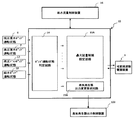
給水ポンプ制御装置15は、図2に示すように、低圧復水ポンプ6、高圧復水ポンプ7、給水ポンプ10及び高圧ドレンポンプ13の運転状態を判別するポンプ運転状態判定回路14を備え、ポンプ運転状態判定回路14からの各ポンプの運転状態により、給水ポンプ10への回転速度指令の最大値を制限する最大流量制限設定回路15Aを設けている。この最大流量制限設定回路15Aによって、各ポンプの容量を超えた運転を防止している。なお、各ポンプの制限流量としては、通常運転に於ける流量の揺らぎ等の制御余裕を考慮した連続運転可能な仕様点流量と、過渡時における運転可能時間を限定したランアウト流量とがある。
As shown in FIG. 2, the feed water
図1に戻り、低圧復水ポンプ6、高圧復水ポンプ7、及び高圧ドレンポンプ13の構成について説明する。これらのポンプは、通常時のプラント給水流量を100%としたときの復水流量及び高圧ドレン流量のそれぞれが1台あたり約33%容量のポンプである。これらの各ポンプをそれぞれ4台並列接続して構成し、通常時のプラント給水流量100%時にはそれぞれ3台運転し、1台を予備機として運用している。
Returning to FIG. 1, the configuration of the low-
可変周波数電源装置9駆動の給水ポンプ10も同様の構成であって、通常時のプラント給水流量を100%としたときの給水流量が1台あたり約33%容量のポンプであり、通常時は3台運転で運用し、1台は予備機として設けている。
The
通常運転中、低圧復水ポンプ6の複数台の内の1台に何らかの故障が発生した場合、故障した低圧復水ポンプ6が1台トリップすると、低圧復水ポンプ6の2台から供給できる給水流量に減少する。このとき、下流側ポンプである高圧復水ポンプ7と可変周波数電源装置9駆動の給水ポンプ10を通常通りに合わせて100%の給水流量で運転を継続すると、上流側の低圧復水ポンプ6が送水可能な流量と下流側の高圧復水ポンプ7と可変周波数電源装置9駆動の給水ポンプ10流量アンバランスにより低圧復水ポンプ6の2台がランアウト領域を超える運転となり、これらの低圧復水ポンプ6が損傷する恐れがある。また、高圧復水ポンプ7と可変周波数電源装置9駆動の給水ポンプ10は、必要吸込み圧力が確保されないためキャビテーションが発生し下流側のポンプが損傷するおそれがある。
During normal operation, if any failure occurs in one of a plurality of low-pressure condensate pumps 6, when one of the failed low-pressure condensate pumps 6 trips, the water supply that can be supplied from the two low-pressure condensate pumps 6. Reduce to flow rate. At this time, if the high-
そこで、ポンプトリップ時の給水系の上流側から下流側に至る流量アンバランスを解消するため、本実施の形態においては、給水ポンプ制御装置15に最大流量制限設定回路15Aを設けている。給水ポンプ制御装置15の構成について、図2を用いて説明する。
Therefore, in order to eliminate the flow rate imbalance from the upstream side to the downstream side of the water supply system when the pump trips, in this embodiment, the maximum flow rate
図2に示すように、給水ポンプ制御装置15は、ポンプ運転状態判定回路14と最大流量制限設定回路15Aと蒸気発生器出力変更要求回路15Bとを備えている。ポンプ運転状態判定回路14には、低圧復水ポンプ6、高圧復水ポンプ7、給水ポンプ10及び高圧ドレンポンプ13の運転状態が入力されている。これらは、例えば各ポンプを駆動する電動機用の電源遮断器の開閉接点などが用いられる。また、最大流量制限設定回路15Aからは、可変周波数電源装置9へ給水ポンプ10の回転速度指令が出力され、蒸気発生器出力変更要求回路15Bからは、蒸気発生器出力制御装置100へ蒸気発生器1の出力変更を要求する出力変更指令が出力される。
As shown in FIG. 2, the feed water
ここで、低圧復水ポンプ6、又は高圧復水ポンプ7のいずれかの複数台の内の1台がトリップした場合、給水ポンプ制御装置15に設けた以下のトリップ時制御手段が実行される。ポンプ運転状態判定回路14からの各復水ポンプの運転状態により、給水ポンプ制御装置15は、可変周波数電源装置9駆動の給水ポンプ6の回転速度指令の最大値を制限する最大流量制限設定回路15Aに設定変更指令を出力する。これにより、最大流量制限設定回路15Aは、最大流量制限値を仕様点流量から、ポンプの過渡時の短時間運転可能なランアウト流量に変更する。この結果、給水ポンプ10の回転速度が減速し、給水流量が減少するので、上流側ポンプの復水ポンプ6,7と下流側ポンプの給水ポンプ10との間の流量アンバランスが無くなる。
Here, when one of the low
また、トリップしたポンプの予備機起動を検知すると、給水ポンプ制御装置15に設けた以下の復帰時制御手段が実行される。給水ポンプ制御装置15は、最大流量制限設定回路15Aに設定復帰指令を出力する。これにより、最大流量制限設定回路15Aは、最大流量制限値をランアウト流量から、仕様点流量に変更する。この結果、通常運転状態に制御が移行されるので、蒸気発生器1に対する必要給水流量と送水給水流量のミスマッチを最小限にすることができ、蒸気発生器1の水位低下量を抑制することができる。
Further, when the start-up of the tripped pump is detected, the following return time control means provided in the feed water
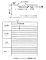
次に、低圧復水ポンプ6の複数台の内の1台がトリップした時の最大流量制限設定回路15Aの設定変更例を図3を用いて説明する。
ここで、説明の便宜のため、仮に仕様点流量をプラント給水流量の110%とし、ランアウト流量をプラント給水流量の130%で運転時間2分以下と設定する。低圧復水ポンプ6の2台運転時におけるランアウト流量は、33.3×2×1.3より86.8%になる。
Next, a setting change example of the maximum flow rate
Here, for convenience of explanation, the specification point flow rate is assumed to be 110% of the plant feed water flow rate, and the runout flow rate is set to 130% of the plant feed water flow rate and the operation time is 2 minutes or less. The run-out flow rate when two low-pressure condensate pumps 6 are operated is 86.8% from 33.3 × 2 × 1.3.
図3において、ポンプ運転状態判定回路14により、低圧復水ポンプ6の複数台の内の1台のトリップを判定した場合、給水ポンプ制御装置15は、可変周波数電源装置9駆動の給水ポンプ10の回転速度指令の最大値を制限する最大流量制限設定回路15Aに設定変更指令を出力する。これにより、最大流量制限設定回路15Aは、最大流量制限値を低圧復水ポンプ6の3台運転の仕様点流量である110%から、ポンプの過渡時の短時間運転可能な低圧復水ポンプ6の2台運転のランアウト流量である86.8%に変更する。この結果、給水ポンプ10の回転速度は減速制御され、給水流量が減少する。このことにより、上流側の低圧復水ポンプ6と下流側の高圧復水ポンプ7、高圧ドレンポンプ13及び可変周波数電源装置9駆動の給水ポンプ10との間の流量アンバランスがなくなり、キャビテーション運転の発生が防止される。
In FIG. 3, when the pump operation
次に、ポンプ運転状態判定回路14が低圧復水ポンプ6の予備機起動を検知すると、給水ポンプ制御装置15は、最大流量制限設定回路15Aに設定復帰指令を出力する。これにより、最大流量制限設定回路15Aは、最大流量制限値を低圧復水ポンプ6の2台運転のランアウト流量である86.8%から、低圧復水ポンプ6の3台運転の仕様点流量である110%に変更する。このことにより、給水ポンプ10の回転速度は増速制御され、給水流量が増加し、通常運転状態に制御が移行される。この結果、プラント給水流量を速やかに確保することができるとともに、蒸気発生器1の水位の低下量を少なくすることができる。
Next, when the pump operation
上述した本発明の給水ポンプ制御装置の第1の実施の形態によれば、復水ポンプ6のトリップ時に蒸気発生器1への給水流量の低下量を小さくし、蒸気発生器1の水位低下量を抑制するとともに、運転継続する復水ポンプ6のランアウト運転の継続を防止することができる。
According to the above-described first embodiment of the feed water pump control device of the present invention, when the
また、上述した本発明の給水ポンプ制御装置の第1の実施の形態によれば、可変周波数電源装置9駆動の給水ポンプ10の回転速度制御を行う給水ポンプ制御装置15が、低圧復水ポンプ6の複数台の内の1台のトリップを検知したときに、給水ポンプ10への回転速度制御指令に対する最大流量制限値を仕様点流量からランアウト流量に変更させるトリップ時制御を実行し、低圧復水ポンプ6の予備機起動を検知したときに、前記最大流量制限値をランアウト流量から仕様点流量に復帰させる復帰時制御を実行しているので、低圧復水ポンプ6の複数台の内の1台がトリップしてから、低圧復水ポンプ6の予備機が起動して通常の給水流量に復帰させる復帰時制御に係る時間を短縮することができる。
Further, according to the above-described first embodiment of the feed water pump control device of the present invention, the feed water
なお、本実施の形態においては、最大流量制限を通常運転時の設定変更に復帰させるための信号として、低圧復水ポンプ6の予備機起動信号を遮断器の接点信号から使用したが、これに限るものではない。例えば、低圧復水ポンプ6に回転速度検出手段を設け、この回転速度検出手段で検出した信号を給水ポンプ制御装置15のポンプ運転状態判定回路14に出力してもよいし、低圧復水ポンプ6の吐出側にポンプ吐出圧力を検出する圧力検出手段を設け、この圧力検出手段で検出した信号を同様にポンプ運転状態判定回路14に出力しもよい。そして、ポンプ起動特性から定まる設定値とこれらの検出値とを比較演算して予備機起動を判断してもよい。ポンプ起動特性から予備機起動を判断することにより、給水ポンプ10のトリップ時制御の実質制御時間が確保できるので、低圧復水ポンプ6のランアウト流量以上の運転発生の可能性が減少する。
In the present embodiment, as a signal for returning the maximum flow rate restriction to the setting change during normal operation, the spare machine start signal of the low
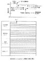
以下、本発明の給水ポンプ制御装置の第2の実施の形態を図面を用いて説明する。図4は本発明の給水ポンプ制御装置の第2の実施の形態における復水ポンプトリップ予備機不起動時の動作を説明する特性図である。図4において、図1乃至図3に示す符号と同符号のものは同一部分であるので、その詳細な説明は省略する。
第1の実施の形態においては、低圧復水ポンプ6の複数台の内の1台がトリップし、予備機が起動した場合の適用について説明したが、本実施の形態においては、低圧復水ポンプ6の複数台の内の1台がトリップし、予備機が起動しない場合についての動作について説明する。したがって、タービン設備、給水ポンプ制御装置15等の構成は第1の実施の形態と同じである。
Hereinafter, a second embodiment of the feed pump control device of the present invention will be described with reference to the drawings. FIG. 4 is a characteristic diagram for explaining the operation when the condensate pump trip preliminary machine is not started in the second embodiment of the feed pump control device of the present invention. In FIG. 4, the same reference numerals as those shown in FIGS. 1 to 3 are the same parts, and detailed description thereof is omitted.
In the first embodiment, the application in the case where one of the plurality of low-pressure condensate pumps 6 trips and the spare machine is activated has been described. In the present embodiment, the low-pressure condensate pump is used. An operation when one of the plurality of 6 trips and the spare machine does not start will be described. Therefore, the configurations of the turbine equipment, the feed water
図4において、ポンプ運転状態判定回路14により、低圧復水ポンプ6の複数台の内の1台のトリップを判定した場合、給水ポンプ制御装置15は、可変周波数電源装置9駆動の給水ポンプ10の回転速度指令の最大値を制限する最大流量制限設定回路15Aに設定変更指令を出力する。これにより、最大流量制限設定回路15Aは、最大流量制限値を低圧復水ポンプ6の3台運転の仕様点流量である110%から、ポンプの過渡時の短時間運転可能な低圧復水ポンプ6の2台運転のランアウト流量である86.8%に変更する。この結果、給水ポンプ10の回転速度は減速制御され、給水流量が減少する。
In FIG. 4, when the pump operation
この後、低圧復水ポンプ6の予備機が起動しない状態が継続すると、2台の低圧復水ポンプ6はランアウト流量の運転が継続するため、運転許容時間を超えると、過負荷トリップしてしまうおそれが生じる。また、低圧復水ポンプ6が全台トリップすると、上流側の低圧復水ポンプ6と下流側の高圧復水ポンプ7及び可変周波数電源装置9駆動の給水ポンプ10との間の流量アンバランスが発生し、キャビテーション運転によるポンプ損傷のおそれが生じる。
After this, if the state where the spare machine of the low-
そこで、例えば予備機起動指令から5秒経過しても予備機起動信号を受け付けない等の状態から、ポンプ運転状態判定回路14が低圧復水ポンプ6の予備機不起動を判定した場合、給水ポンプ制御装置15は、最大流量制限設定回路15Aに再度設定変更指令を出力する。これにより、最大流量制限設定回路15Aは、最大流量制限値を低圧復水ポンプ6の2台運転のランアウト流量である86.8%から、低圧復水ポンプ6の2台運転の仕様点流量である73.3%(33.3×2×1.1)に変更する。この結果、低圧復水ポンプ6の運転許容時間を越えることによる過負荷トリップや、可変周波数電源装置9駆動の給水ポンプ10の吸込圧力低下によるキャビテーション運転を防止することができる。
Therefore, for example, when the pump operation
上述した本発明の給水ポンプ制御装置の第2の実施の形態によれば、上述した第1の実施の形態と同様な効果を得ることができるとともに、低圧復水ポンプ6の予備機が不起動となっても、運転継続している低圧復水ポンプ6の過負荷トリップや給水ポンプ10のキャビテーション運転を防止することができる。
According to the second embodiment of the feed water pump control device of the present invention described above, the same effect as that of the first embodiment described above can be obtained, and the spare machine of the low
以下、本発明の給水ポンプ制御装置の第3の実施の形態を図面を用いて説明する。図5は本発明の給水ポンプ制御装置の第3の実施の形態における復水ポンプトリップ予備機不起動時の動作を説明する特性図である。図5において、図1乃至図4に示す符号と同符号のものは同一部分であるので、その詳細な説明は省略する。
第2の実施の形態においては、低圧復水ポンプ6の複数台の内の1台がトリップし、予備機が起動しない場合の適用について説明したが、本実施の形態においては、同様に予備機が起動しない場合の動作の他の実施例について説明する。したがって、タービン設備、給水ポンプ制御装置15等の構成は第1の実施の形態と同じである。
Hereinafter, a third embodiment of the feed pump control device of the present invention will be described with reference to the drawings. FIG. 5 is a characteristic diagram for explaining the operation when the condensate pump trip preliminary machine is not started in the third embodiment of the feed pump control device of the present invention. In FIG. 5, the same reference numerals as those shown in FIGS. 1 to 4 are the same parts, and detailed description thereof is omitted.
In the second embodiment, the case where one of the plurality of low-pressure condensate pumps 6 trips and the spare machine does not start has been described. However, in the present embodiment, the spare machine is similarly used. Another embodiment of the operation when is not activated will be described. Therefore, the configurations of the turbine equipment, the feed water
図5において、ポンプ運転状態判定回路14により、低圧復水ポンプ6の複数台の内の1台のトリップを判定した場合、給水ポンプ制御装置15と最大流量制限設定回路15Aの動作は、第2の実施の形態と同様であり、ポンプ運転状態判定回路14が予備機不起動を判定した後に、運転継続した低圧復水ポンプ6の2台分の仕様点流量に給水ポンプ10の最大流量制限を再変更している。
In FIG. 5, when the pump operation
この結果、上述したように、運転継続している低圧復水ポンプ6の過負荷トリップや給水ポンプ10のキャビテーション運転を防止することはできるが、蒸気発生器1が必要とする必要給水流量と給水ポンプ10が蒸気発生器1に送水する給水流量とはアンバランスのままになり、蒸気発生器1の水位低下によるプラントトリップの可能性が生じるという問題がある。
As a result, as described above, although the overload trip of the low-
そこで、給水ポンプ制御装置15は、ポンプ運転状態判定回路14が予備機不起動を判定した後に、蒸気発生器出力変更要求回路15Bから蒸気発生器出力制御装置100へ出力変更指令を出力する。これにより、蒸気発生器出力制御装置100が、運転継続した低圧復水ポンプ6の台数分の仕様点流量以下の出力まで、蒸気発生器1の出力を低下させる。このことにより、蒸気発生器1の必要給水流量が低下するので、蒸気発生器1が必要とする必要給水流量と低圧復水ポンプ6、高圧復水ポンプ7、高圧ドレンポンプ13及び給水ポンプ10が蒸気発生器1に送水する給水流量とがバランスする。この結果、蒸気発生器1の水位低下によるプラントトリップの発生は防止できる。
Therefore, the feed water
上述した本発明の給水ポンプ制御装置の第3の実施の形態によれば、上述した第2の実施の形態と同様な効果を得ることができるとともに、低圧復水ポンプ6の予備機が不起動となっても、蒸気発生器1の水位低下によるプラントトリップの発生を防止することができる。
According to the third embodiment of the feed water pump control device of the present invention described above, the same effect as the second embodiment described above can be obtained, and the spare machine of the low
以下、本発明の給水ポンプ制御装置の第4の実施の形態を図面を用いて説明する。図6は本発明の給水ポンプ制御装置の第4の実施の形態における復水ポンプトリップ予備機不起動時の動作を説明する特性図である。図6において、図1乃至図5に示す符号と同符号のものは同一部分であるので、その詳細な説明は省略する。
第3の実施の形態においては、低圧復水ポンプ6の複数台の内の1台がトリップし、予備機が起動しない場合の適用について説明したが、本実施の形態においては、同様に予備機が起動しない場合の動作の更に他の実施例について説明する。したがって、タービン設備、給水ポンプ制御装置15等の構成は第1の実施の形態と同じである。
Hereinafter, a fourth embodiment of the feed water pump control device of the present invention will be described with reference to the drawings. FIG. 6 is a characteristic diagram for explaining the operation when the condensate pump trip spare machine is not started in the fourth embodiment of the feed pump control device of the present invention. In FIG. 6, the same reference numerals as those shown in FIGS. 1 to 5 are the same parts, and detailed description thereof is omitted.
In the third embodiment, the application in the case where one of the plurality of low-pressure condensate pumps 6 trips and the spare machine does not start has been described. Still another embodiment of the operation when the computer does not start will be described. Therefore, the configurations of the turbine equipment, the feed water
図6において、ポンプ運転状態判定回路14により、低圧復水ポンプ6の複数台の内の1台のトリップを判定した場合、給水ポンプ制御装置15と最大流量制限設定回路15Aと蒸気発生器出力変更要求回路15Bの動作は、第3の実施の形態と同様であり、ポンプ運転状態判定回路14が予備機不起動を判定した後に、運転継続した低圧復水ポンプ6の2台分の仕様点流量に給水ポンプ10の最大流量制限を再変更するとともに、運転継続した低圧復水ポンプ6の台数分の仕様点流量以下の出力まで、蒸気発生器1の出力を低下させる。
In FIG. 6, when it is determined by the pump operation
この結果、このプラント出力状態において、継続運転は可能となるが、給水装置を構成する各ポンプの1台当たりの運転容量が異なるという問題がある。つまり、低圧復水ポンプ6は2台で運転しているのに対し、高圧復水ポンプ7と給水ポンプ10はそれぞれ3台で運転している。過渡的な運用であれば問題とならないが、継続運転する場合には、3台で運転するこれらのポンプも2台運転に移行するべきである。
As a result, continuous operation is possible in this plant output state, but there is a problem that the operation capacity per pump of each pump constituting the water supply apparatus is different. That is, while the low-
そこで、給水ポンプ制御装置15は、ポンプ運転状態判定回路14が予備機不起動を判定した後に、蒸気発生器出力変更要求回路15Bから蒸気発生器出力制御装置100へ出力変更指令を出力するとともに、高圧復水ポンプ7及び給水ポンプ10をそれぞれ1台停止させる。このことにより、運転継続した低圧復水ポンプ6と高圧復水ポンプ7と給水ポンプ10の1台当たりの運転容量がバランスされるとともに、蒸気発生器1が必要とする必要給水流量と低圧復水ポンプ6、高圧復水ポンプ7、高圧ドレンポンプ13及び給水ポンプ10が蒸気発生器1に送水する給水流量とがバランスする。この結果、蒸気発生器1の水位低下によるプラントトリップの発生は防止できる。
Therefore, the feed water
上述した本発明の給水ポンプ制御装置の第4の実施の形態によれば、上述した第1乃至第3の実施の形態と同様な効果を得ることができる。 According to the fourth embodiment of the feed water pump control device of the present invention described above, the same effects as those of the first to third embodiments described above can be obtained.
なお、本発明の実施の形態においては、低圧復水ポンンプ6の複数台の内の1台のトリップの場合を例に説明したが、高圧復水ポンプ7の複数台の内の1台のトリップにおける最大給水流量制限変更についても同様である。図7に低圧復水ポンプ6、高圧復水ポンプ7の各ポンプのトリップ、予備機起動又は不起動の場合の最大給水流量制限変更の例を示す。
In the embodiment of the present invention, the case of one trip among a plurality of low-pressure condensate pumps 6 has been described as an example, but one trip among a plurality of high-pressure condensate pumps 7 is described. The same applies to the maximum water supply flow rate restriction change in FIG. 7 shows an example of the maximum water supply flow rate restriction change in the case of tripping of each of the low-
また、本発明の実施の形態においては、2段構成の復水ポンプを備えた発電プラントに適用した場合を説明したが、これに限るものではない。例えば、1段構成の復水ポンプを備えた発電プラントにも適用できる。また、各ポンプを4台構成とした例で説明しているが、例えば3台や5台構成であっても適用できる。 In the embodiment of the present invention, the case where the present invention is applied to a power plant including a condensate pump having a two-stage configuration has been described. However, the present invention is not limited to this. For example, the present invention can be applied to a power plant including a single-stage condensate pump. Further, although an example in which each pump is configured with four units has been described, for example, a configuration with three units or five units can be applied.
さらに、本発明の実施の形態においては、ドレンポンプによるドレンアップを備えた発電プラントに適用した場合を説明したが、これに限るものではない。例えば、ドレンを下流の給水加熱器へドレンカスケードする発電プラントにも適用しても同一の効果を奏することができる。 Furthermore, in the embodiment of the present invention, the case where the present invention is applied to a power plant provided with a drain up by a drain pump has been described, but the present invention is not limited to this. For example, the same effect can be obtained even if the drain is applied to a power generation plant that drains cascade to a downstream feed water heater.
1 蒸気発生器
2 高圧タービン
3 湿分分離加熱器
4 低圧タービン
5 復水器
6 低圧復水ポンプ
7 高圧復水ポンプ
8 低圧給水加熱器
9 可変周波数電源装置
10 給水ポンプ
11 高圧ドレンタンク
12 高圧給水加熱器
13 高圧ドレンポンプ
14 ポンプ運転状態判定回路
15 給水ポンプ制御装置
15A 最大流量制限設定回路
15B 蒸気発生器出力変更要求回路
16 給水流量制御装置
DESCRIPTION OF SYMBOLS 1 Steam generator 2
Claims (3)
前記給水ポンプ制御装置は、運転中の前記復水ポンプのトリップを検知すると、前記可変周波数電源装置への周波数制御指令に対する最大流量制限値を過渡時のみ短時間運転が認められるランアウト流量に変更するトリップ時制御手段と、前記復水ポンプの予備機起動を検知すると、前記最大流量制限値をランアウト流量から通常流量に変更する復帰時制御手段と、前記復水ポンプの予備機不起動を検知すると、前記最大流量制限値を前記ランアウト流量から復水ポンプの運転継続した台数の通常運転流量に変更する制御手段とを備えた
ことを特徴とする給水ポンプ制御装置。 A condensate pump installed in parallel to boost the condensate from the condenser, and a plurality of units to further boost the condensate boosted by the condensate pump and supply it to the steam generator. A water supply device having a water supply pump installed in parallel and a variable frequency power supply device that drives a motor of the water supply pump at a variable speed, and outputs a frequency control command to the variable frequency power supply device in the water supply device, A feed water pump control device for controlling the rotation speed of the feed water pump,
When the feed pump control device detects a trip of the condensate pump during operation, it changes the maximum flow rate limit value for the frequency control command to the variable frequency power supply device to a runout flow rate that allows a short-time operation only during a transient state. When detecting the trip time control means and the start-up of the condensate pump spare machine, detecting the return time control means for changing the maximum flow rate limit value from the run-out flow rate to the normal flow rate, and the condensate pump spare machine inactive And a control means for changing the maximum flow rate limit value from the runout flow rate to a normal operation flow rate of the number of condensate pumps that have been operated .
前記給水ポンプ制御装置は、前記復水ポンプの予備機不起動を検知すると、前記蒸気発生器の出力減少を要求する指令を前記蒸気発生器の出力制御装置に対して出力する制御手段を備えた
ことを特徴とする給水ポンプ制御装置。 In the feed water pump control device according to claim 1 ,
The feed water pump control device comprises control means for outputting a command for requesting a reduction in the output of the steam generator to the output control device of the steam generator when detecting that the spare machine of the condensate pump is not started. A feed water pump control device characterized by that.
前記給水ポンプ制御装置は、前記復水ポンプの予備機不起動を検知すると、運転継続した復水ポンプの運転台数と同数になるように、前記給水ポンプの運転台数を変更する制御手段を備えた
ことを特徴とする給水ポンプ制御装置。 In the feed water pump control device according to claim 2 ,
The water supply pump control device includes control means for changing the number of operating water pumps so that the number of operating condensate pumps is the same as the number of operating condensate pumps when the condensate pump is not activated. A feed water pump control device characterized by that.
Priority Applications (2)
| Application Number | Priority Date | Filing Date | Title |
|---|---|---|---|
| JP2010271324A JP5550020B2 (en) | 2010-12-06 | 2010-12-06 | Water supply pump controller |
| US13/310,403 US20120183413A1 (en) | 2010-12-06 | 2011-12-02 | Reactor Feedwater Pump Control System |
Applications Claiming Priority (1)
| Application Number | Priority Date | Filing Date | Title |
|---|---|---|---|
| JP2010271324A JP5550020B2 (en) | 2010-12-06 | 2010-12-06 | Water supply pump controller |
Publications (2)
| Publication Number | Publication Date |
|---|---|
| JP2012122626A JP2012122626A (en) | 2012-06-28 |
| JP5550020B2 true JP5550020B2 (en) | 2014-07-16 |
Family
ID=46490897
Family Applications (1)
| Application Number | Title | Priority Date | Filing Date |
|---|---|---|---|
| JP2010271324A Expired - Fee Related JP5550020B2 (en) | 2010-12-06 | 2010-12-06 | Water supply pump controller |
Country Status (2)
| Country | Link |
|---|---|
| US (1) | US20120183413A1 (en) |
| JP (1) | JP5550020B2 (en) |
Cited By (1)
| Publication number | Priority date | Publication date | Assignee | Title |
|---|---|---|---|---|
| CN106774472A (en) * | 2016-11-14 | 2017-05-31 | 上海明华电力技术工程有限公司 | The frequency conversion energy-saving control method of pumping system is closed to pump for high pressure |
Families Citing this family (7)
| Publication number | Priority date | Publication date | Assignee | Title |
|---|---|---|---|---|
| CN102878092B (en) * | 2012-10-16 | 2015-04-08 | 章礼道 | Novel energy-saving and speed-regulation electric water feeding pump system |
| CN103133319B (en) * | 2013-02-20 | 2016-01-27 | 浙江省电力公司电力科学研究院 | A kind of condensing generator set Condensate Pump Frequency Conversion controlling method and system |
| CN105811782B (en) * | 2014-12-31 | 2018-05-18 | 中核陕西铀浓缩有限公司 | The special integrated variable frequency power supply of uranium enrichment |
| CN105387099B (en) * | 2015-12-22 | 2017-02-15 | 扬州大学 | Brake device for high-flow inclined and horizontal water pump units, and application method |
| JP6771338B2 (en) * | 2016-08-26 | 2020-10-21 | 三菱パワー株式会社 | Pump system and its operation method and power plant |
| WO2018140905A1 (en) | 2017-01-27 | 2018-08-02 | Franklin Electric Co., Inc. | Motor drive system and method |
| CN110456835A (en) * | 2019-08-28 | 2019-11-15 | 西安陕鼓动力股份有限公司 | Condenser hotwell tank level control system |
Family Cites Families (10)
| Publication number | Priority date | Publication date | Assignee | Title |
|---|---|---|---|---|
| US4302288A (en) * | 1978-10-23 | 1981-11-24 | General Electric Company | Fluid level control system |
| JPS588905A (en) * | 1981-07-08 | 1983-01-19 | 株式会社日立製作所 | Method of controlling feedwater for steam generator |
| JPS60201008A (en) * | 1984-03-26 | 1985-10-11 | Hitachi Ltd | Method and apparatus for controlling operation of plant |
| US4650633A (en) * | 1984-07-02 | 1987-03-17 | General Electric Company | Method and apparatus for protection of pump systems |
| JPS61237903A (en) * | 1985-04-15 | 1986-10-23 | 株式会社日立製作所 | Controller for water level in drain tank for feedwater heater |
| JPH041499A (en) * | 1990-04-13 | 1992-01-06 | Toshiba Corp | Discharge flow controller for pump |
| JP2803486B2 (en) * | 1992-09-18 | 1998-09-24 | 株式会社日立製作所 | Fluid plant |
| JPH08116629A (en) * | 1994-10-18 | 1996-05-07 | Toshiba Corp | Power supply for circulating pump for reactor |
| JP3800713B2 (en) * | 1996-09-12 | 2006-07-26 | 株式会社明電舎 | Water distribution facility control equipment |
| JP2009204255A (en) * | 2008-02-28 | 2009-09-10 | Hitachi-Ge Nuclear Energy Ltd | Water supply device for steam generator |
-
2010
- 2010-12-06 JP JP2010271324A patent/JP5550020B2/en not_active Expired - Fee Related
-
2011
- 2011-12-02 US US13/310,403 patent/US20120183413A1/en not_active Abandoned
Cited By (2)
| Publication number | Priority date | Publication date | Assignee | Title |
|---|---|---|---|---|
| CN106774472A (en) * | 2016-11-14 | 2017-05-31 | 上海明华电力技术工程有限公司 | The frequency conversion energy-saving control method of pumping system is closed to pump for high pressure |
| CN106774472B (en) * | 2016-11-14 | 2019-11-12 | 上海明华电力科技有限公司 | The frequency conversion energy-saving control method of pumping system is closed to pump for high pressure |
Also Published As
| Publication number | Publication date |
|---|---|
| US20120183413A1 (en) | 2012-07-19 |
| JP2012122626A (en) | 2012-06-28 |
Similar Documents
| Publication | Publication Date | Title |
|---|---|---|
| JP5550020B2 (en) | Water supply pump controller | |
| US8963350B1 (en) | Method and apparatus for extended operation of steam turbines in islanding mode | |
| JP6067535B2 (en) | Steam turbine plant start-up method | |
| JP2015528561A (en) | Control of variable speed drives for chiller coast-through. | |
| JP2012167571A (en) | Uniaxial combined cycle power generation plant, and method of operating the same | |
| JP2009204255A (en) | Water supply device for steam generator | |
| JP2012163279A (en) | Device for controlling flow rate of feed-water, and power plant using the same | |
| JP2008101494A (en) | Low-pressure steam turbine system and control method | |
| JP5562806B2 (en) | Reactor water level control system | |
| US8467491B2 (en) | Feedwater controller, nuclear power plant and method for controlling feedwater | |
| JP5415171B2 (en) | Water wheel governor | |
| JP7268573B2 (en) | Power generation system and method of starting power generation system | |
| JP2933294B2 (en) | Water supply equipment for nuclear power plants | |
| JP4709809B2 (en) | Water supply control device, nuclear power plant, and water supply control method | |
| JP2008075580A (en) | Low-pressure steam turbine system and method of controlling it | |
| JP4560481B2 (en) | Steam turbine plant | |
| JPS62189385A (en) | Control device for number of driving pumps | |
| JP2010084697A (en) | Pump cavitation-free control device and pump cavitation-free control method | |
| JP2018091224A (en) | Control system, steam turbine, power-generating plant and control method | |
| JP2509631B2 (en) | Pump controller | |
| JP2020139659A (en) | Water supply system, power generation plant, operation method of water supply system and recording medium in which control program for water supply system is recorded | |
| JP6392131B2 (en) | VPC power generation control device | |
| JPH09145893A (en) | Condensate and feed device | |
| JPH08166106A (en) | Water supply controller | |
| JP2685948B2 (en) | Water supply and condensate pump controller |
Legal Events
| Date | Code | Title | Description |
|---|---|---|---|
| A621 | Written request for application examination |
Free format text: JAPANESE INTERMEDIATE CODE: A621 Effective date: 20130213 |
|
| A977 | Report on retrieval |
Free format text: JAPANESE INTERMEDIATE CODE: A971007 Effective date: 20131212 |
|
| A131 | Notification of reasons for refusal |
Free format text: JAPANESE INTERMEDIATE CODE: A131 Effective date: 20131217 |
|
| A521 | Written amendment |
Free format text: JAPANESE INTERMEDIATE CODE: A523 Effective date: 20140130 |
|
| TRDD | Decision of grant or rejection written | ||
| A01 | Written decision to grant a patent or to grant a registration (utility model) |
Free format text: JAPANESE INTERMEDIATE CODE: A01 Effective date: 20140422 |
|
| A61 | First payment of annual fees (during grant procedure) |
Free format text: JAPANESE INTERMEDIATE CODE: A61 Effective date: 20140512 |
|
| R150 | Certificate of patent or registration of utility model |
Ref document number: 5550020 Country of ref document: JP Free format text: JAPANESE INTERMEDIATE CODE: R150 |
|
| LAPS | Cancellation because of no payment of annual fees |