JP5543689B2 - Air conditioner with electric expansion valve - Google Patents
Air conditioner with electric expansion valve Download PDFInfo
- Publication number
- JP5543689B2 JP5543689B2 JP2008047991A JP2008047991A JP5543689B2 JP 5543689 B2 JP5543689 B2 JP 5543689B2 JP 2008047991 A JP2008047991 A JP 2008047991A JP 2008047991 A JP2008047991 A JP 2008047991A JP 5543689 B2 JP5543689 B2 JP 5543689B2
- Authority
- JP
- Japan
- Prior art keywords
- temperature
- compressor
- condenser
- fluid
- expansion valve
- Prior art date
- Legal status (The legal status is an assumption and is not a legal conclusion. Google has not performed a legal analysis and makes no representation as to the accuracy of the status listed.)
- Expired - Fee Related
Links
- 239000012809 cooling fluid Substances 0.000 claims description 54
- 239000012530 fluid Substances 0.000 claims description 48
- 238000004781 supercooling Methods 0.000 claims description 30
- 238000004378 air conditioning Methods 0.000 claims description 29
- 238000013021 overheating Methods 0.000 claims description 23
- 230000033228 biological regulation Effects 0.000 claims description 20
- 238000001704 evaporation Methods 0.000 claims description 18
- 230000008020 evaporation Effects 0.000 claims description 17
- 238000009529 body temperature measurement Methods 0.000 claims description 16
- 238000005259 measurement Methods 0.000 claims description 16
- 239000000523 sample Substances 0.000 claims description 12
- 230000004044 response Effects 0.000 claims description 9
- 238000009530 blood pressure measurement Methods 0.000 claims description 8
- 239000003990 capacitor Substances 0.000 claims description 7
- 230000007480 spreading Effects 0.000 claims description 2
- 238000001816 cooling Methods 0.000 claims 3
- 238000010586 diagram Methods 0.000 description 12
- 238000006073 displacement reaction Methods 0.000 description 6
- 239000007788 liquid Substances 0.000 description 4
- 230000007423 decrease Effects 0.000 description 2
- 230000018044 dehydration Effects 0.000 description 2
- 238000006297 dehydration reaction Methods 0.000 description 2
- 238000000034 method Methods 0.000 description 2
- 238000004088 simulation Methods 0.000 description 2
- 239000002253 acid Substances 0.000 description 1
- 150000007513 acids Chemical class 0.000 description 1
- 230000008859 change Effects 0.000 description 1
- 230000005494 condensation Effects 0.000 description 1
- 238000009833 condensation Methods 0.000 description 1
- 230000001276 controlling effect Effects 0.000 description 1
- 230000002596 correlated effect Effects 0.000 description 1
- 230000000875 corresponding effect Effects 0.000 description 1
- 230000003247 decreasing effect Effects 0.000 description 1
- 238000011156 evaluation Methods 0.000 description 1
- OMRRUNXAWXNVFW-UHFFFAOYSA-N fluoridochlorine Chemical compound ClF OMRRUNXAWXNVFW-UHFFFAOYSA-N 0.000 description 1
- 238000010438 heat treatment Methods 0.000 description 1
- 238000010348 incorporation Methods 0.000 description 1
- 238000013507 mapping Methods 0.000 description 1
- 239000000203 mixture Substances 0.000 description 1
- 239000002245 particle Substances 0.000 description 1
- 230000009467 reduction Effects 0.000 description 1
- 238000012552 review Methods 0.000 description 1
- 239000013589 supplement Substances 0.000 description 1
- 230000000153 supplemental effect Effects 0.000 description 1
- 238000012360 testing method Methods 0.000 description 1
- 238000012546 transfer Methods 0.000 description 1
Images


Classifications
-
- F—MECHANICAL ENGINEERING; LIGHTING; HEATING; WEAPONS; BLASTING
- F25—REFRIGERATION OR COOLING; COMBINED HEATING AND REFRIGERATION SYSTEMS; HEAT PUMP SYSTEMS; MANUFACTURE OR STORAGE OF ICE; LIQUEFACTION SOLIDIFICATION OF GASES
- F25B—REFRIGERATION MACHINES, PLANTS OR SYSTEMS; COMBINED HEATING AND REFRIGERATION SYSTEMS; HEAT PUMP SYSTEMS
- F25B49/00—Arrangement or mounting of control or safety devices
- F25B49/02—Arrangement or mounting of control or safety devices for compression type machines, plants or systems
- F25B49/022—Compressor control arrangements
-
- F—MECHANICAL ENGINEERING; LIGHTING; HEATING; WEAPONS; BLASTING
- F25—REFRIGERATION OR COOLING; COMBINED HEATING AND REFRIGERATION SYSTEMS; HEAT PUMP SYSTEMS; MANUFACTURE OR STORAGE OF ICE; LIQUEFACTION SOLIDIFICATION OF GASES
- F25B—REFRIGERATION MACHINES, PLANTS OR SYSTEMS; COMBINED HEATING AND REFRIGERATION SYSTEMS; HEAT PUMP SYSTEMS
- F25B41/00—Fluid-circulation arrangements
- F25B41/30—Expansion means; Dispositions thereof
- F25B41/31—Expansion valves
- F25B41/34—Expansion valves with the valve member being actuated by electric means, e.g. by piezoelectric actuators
-
- F—MECHANICAL ENGINEERING; LIGHTING; HEATING; WEAPONS; BLASTING
- F25—REFRIGERATION OR COOLING; COMBINED HEATING AND REFRIGERATION SYSTEMS; HEAT PUMP SYSTEMS; MANUFACTURE OR STORAGE OF ICE; LIQUEFACTION SOLIDIFICATION OF GASES
- F25B—REFRIGERATION MACHINES, PLANTS OR SYSTEMS; COMBINED HEATING AND REFRIGERATION SYSTEMS; HEAT PUMP SYSTEMS
- F25B2341/00—Details of ejectors not being used as compression device; Details of flow restrictors or expansion valves
- F25B2341/06—Details of flow restrictors or expansion valves
- F25B2341/063—Feed forward expansion valves
-
- F—MECHANICAL ENGINEERING; LIGHTING; HEATING; WEAPONS; BLASTING
- F25—REFRIGERATION OR COOLING; COMBINED HEATING AND REFRIGERATION SYSTEMS; HEAT PUMP SYSTEMS; MANUFACTURE OR STORAGE OF ICE; LIQUEFACTION SOLIDIFICATION OF GASES
- F25B—REFRIGERATION MACHINES, PLANTS OR SYSTEMS; COMBINED HEATING AND REFRIGERATION SYSTEMS; HEAT PUMP SYSTEMS
- F25B2600/00—Control issues
- F25B2600/17—Control issues by controlling the pressure of the condenser
-
- F—MECHANICAL ENGINEERING; LIGHTING; HEATING; WEAPONS; BLASTING
- F25—REFRIGERATION OR COOLING; COMBINED HEATING AND REFRIGERATION SYSTEMS; HEAT PUMP SYSTEMS; MANUFACTURE OR STORAGE OF ICE; LIQUEFACTION SOLIDIFICATION OF GASES
- F25B—REFRIGERATION MACHINES, PLANTS OR SYSTEMS; COMBINED HEATING AND REFRIGERATION SYSTEMS; HEAT PUMP SYSTEMS
- F25B2700/00—Sensing or detecting of parameters; Sensors therefor
- F25B2700/21—Temperatures
- F25B2700/2117—Temperatures of an evaporator
- F25B2700/21171—Temperatures of an evaporator of the fluid cooled by the evaporator
- F25B2700/21172—Temperatures of an evaporator of the fluid cooled by the evaporator at the inlet
-
- F—MECHANICAL ENGINEERING; LIGHTING; HEATING; WEAPONS; BLASTING
- F25—REFRIGERATION OR COOLING; COMBINED HEATING AND REFRIGERATION SYSTEMS; HEAT PUMP SYSTEMS; MANUFACTURE OR STORAGE OF ICE; LIQUEFACTION SOLIDIFICATION OF GASES
- F25B—REFRIGERATION MACHINES, PLANTS OR SYSTEMS; COMBINED HEATING AND REFRIGERATION SYSTEMS; HEAT PUMP SYSTEMS
- F25B2700/00—Sensing or detecting of parameters; Sensors therefor
- F25B2700/21—Temperatures
- F25B2700/2117—Temperatures of an evaporator
- F25B2700/21171—Temperatures of an evaporator of the fluid cooled by the evaporator
- F25B2700/21173—Temperatures of an evaporator of the fluid cooled by the evaporator at the outlet
-
- Y—GENERAL TAGGING OF NEW TECHNOLOGICAL DEVELOPMENTS; GENERAL TAGGING OF CROSS-SECTIONAL TECHNOLOGIES SPANNING OVER SEVERAL SECTIONS OF THE IPC; TECHNICAL SUBJECTS COVERED BY FORMER USPC CROSS-REFERENCE ART COLLECTIONS [XRACs] AND DIGESTS
- Y02—TECHNOLOGIES OR APPLICATIONS FOR MITIGATION OR ADAPTATION AGAINST CLIMATE CHANGE
- Y02B—CLIMATE CHANGE MITIGATION TECHNOLOGIES RELATED TO BUILDINGS, e.g. HOUSING, HOUSE APPLIANCES OR RELATED END-USER APPLICATIONS
- Y02B30/00—Energy efficient heating, ventilation or air conditioning [HVAC]
- Y02B30/70—Efficient control or regulation technologies, e.g. for control of refrigerant flow, motor or heating
Description
本発明は、自動車用の空調装置に関する。 The present invention relates to an air conditioner for an automobile.
このタイプの空調装置は、冷却流体が順次循環するコンプレッサ、コンデンサ又はガス冷却器、膨張装置及び蒸発器を含む空調回路を備えている。 This type of air conditioner includes an air conditioner circuit that includes a compressor, condenser or gas cooler, an expansion device and an evaporator through which a cooling fluid circulates in sequence.
コンプレッサは、冷却流体を圧縮してそれを高圧にし、次にそれを、コンデンサに伝送し、そこで冷却される。膨張装置内で、冷却流体は、その圧力を低下させるように膨張される。次に低圧流体は、蒸発器を通過し、コンプレッサ内に戻る前に、そこで蒸発する。蒸発器を通り抜ける空気流は、冷却されるか、又は温度調節され、自動車の居住空間に向けて送られる。 The compressor compresses the cooling fluid to bring it to a high pressure and then transmits it to the condenser where it is cooled. Within the expansion device, the cooling fluid is expanded to reduce its pressure. The low pressure fluid then passes through the evaporator and evaporates there before returning to the compressor. The air flow through the evaporator is cooled or temperature-controlled and sent towards the car's living space.
膨張した流体の流量を制御するために、膨張装置として、電気膨張弁を使用することが知られている。 In order to control the flow rate of the expanded fluid, it is known to use an electric expansion valve as an expansion device.
かかる膨張弁の開放度は、幾つかの作動パラメータに応じて調整された指令信号によって調節される。 The degree of opening of such an expansion valve is adjusted by a command signal adjusted according to several operating parameters.
例えば、蒸発器の出口に設けられているセンサによって提供される圧力及び温度測定に応じて、電気膨張弁の通過断面を調節することが知られている。しかし、蒸発器の出口で使用されるタイプの低圧センサは高価である。 For example, it is known to adjust the passage cross section of an electric expansion valve in response to pressure and temperature measurements provided by sensors provided at the outlet of the evaporator. However, the type of low pressure sensor used at the outlet of the evaporator is expensive.
一般的に言って、公知の装置は、空調の作動条件に応じて、電気膨張弁の開放度を最適化することはできず、かつ多数のセンサを使用するため、装置の全体的なコストは、著しく大となる。その上、かかる装置では、様々な個所において、センサを設けることを必要とし、そのため、装置は、より複雑に、かつ場所を占めるものとなる。 Generally speaking, the known device cannot optimize the opening degree of the electric expansion valve according to the operating conditions of the air conditioning, and uses a large number of sensors, so the overall cost of the device is , Become significantly larger. In addition, such devices require the provision of sensors at various locations, which makes the device more complex and occupying space.
本発明は、空調回路を備えた自動車用の空調装置を改善することを目的としている。空調回路は、冷却流体が順次循環するコンプレッサ、コンデンサ又はガス冷却器、開放度が指令信号に応じて変化する電気膨張弁、及び蒸発器を備えている。応用例として、場合により、装置に内部交換器を設けることがある。装置は、選択された調節法則に応じて、蒸発器の過熱、又はコンデンサの過冷却に関する指令を調節するように、膨張弁の指令信号を制御できる制御ユニットを更に含んでいる。 An object of the present invention is to improve an automobile air conditioner provided with an air conditioning circuit. The air conditioning circuit includes a compressor in which a cooling fluid circulates sequentially, a condenser or a gas cooler, an electric expansion valve whose opening degree changes according to a command signal, and an evaporator. As an application example, an apparatus may be provided with an internal exchanger in some cases. The apparatus further includes a control unit that can control the command signal of the expansion valve to adjust the command for evaporator overheating or condenser subcooling, depending on the selected regulation law.
コンプレッサの弁の指令信号は、次のことを可能にする。
− 最小限のセンサを有し、かつ最適な電気構造を得ること。
− 最大の最適性能係数(COP)を有すること。
− コンプレッサの送り出し、又は吸い込み温度を限定するために、装置を保護すること。
Compressor valve command signals enable the following:
-To obtain an optimal electrical structure with a minimum of sensors.
-Have the maximum optimum coefficient of performance (COP);
-Protect the device to limit the temperature at which the compressor is delivered or sucked.
本発明は、最小数のセンサを使用して、空調の性能係数(COP)を、このようにして最適化すること、及びそれに伴い、装置のコストを減少させることを可能にする。 The present invention makes it possible to optimize the coefficient of performance (COP) of the air conditioning in this way using a minimum number of sensors and thus reduce the cost of the device.
補足的又は代替的な、本発明の空調装置の任意的な特徴を、次にあげる。 Optional features of the air conditioner of the present invention, either supplemental or alternative, are listed below.
− 制御ユニットは、指令の程度を、指令の程度の設定値と比較して、指令の程度の調節を行うことができる。 The control unit can adjust the command level by comparing the command level with the set value of the command level.
− 過熱に関する程度は、蒸発器のレベルでなされる2つの温度測定の間の差に対応している。 The degree of overheating corresponds to the difference between the two temperature measurements made at the level of the evaporator.
− 2つの温度測定は、蒸発器の入口及び出口での流体の温度に、それぞれ対応している。 The two temperature measurements correspond respectively to the temperature of the fluid at the inlet and outlet of the evaporator.
− 装置は、2つの温度測定を提供できる、蒸発器の入口及び出口での流体と接触しうる2つの温度センサを備えている。 The device comprises two temperature sensors that can contact the fluid at the inlet and outlet of the evaporator, which can provide two temperature measurements;
− 2つの温度測定は、蒸発器に広がる空気流の最高温度及び最低温度に、それぞれ対応している。 -The two temperature measurements correspond respectively to the highest and lowest temperature of the air flow spreading over the evaporator.
− 装置は、最高温度及び最低温度の測定をそれぞれ提供できる、蒸発器の放熱ひれ内、又は蒸発器の後方に配置された2つの温度プローブを有する。 -The device has two temperature probes located in the evaporator fin or behind the evaporator, which can provide the highest and lowest temperature measurements, respectively.
− コンプレッサは、通過断面が指令信号に応じて変化する制御弁を備えた外部制御コンプレッサであり、制御ユニットは、温度測定に応じて計算される蒸発器の蒸発温度を調節するように、コンプレッサの指令信号を制御できる。 The compressor is an externally controlled compressor with a control valve whose cross section changes in response to the command signal, the control unit of the compressor to adjust the evaporation temperature of the evaporator calculated in response to the temperature measurement The command signal can be controlled.
− 過冷却に関する程度は、冷却流体の過冷却温度に対応する。 -The degree of supercooling corresponds to the supercooling temperature of the cooling fluid.
− 装置は、過冷却温度の測定を提供できる、コンデンサの出口での流体と接触しうる温度プローブを含んでいる。 The device includes a temperature probe that can contact the fluid at the outlet of the condenser, which can provide a measure of the supercooling temperature;
− 装置は、過冷却温度を測定するように、膨張弁の入口での流体と接触しうる温度プローブを含んでいる。 The device includes a temperature probe that can contact the fluid at the inlet of the expansion valve to measure the supercooling temperature;
− コンプレッサは、外部制御であり、制御ユニットは、コンプレッサの出口での温度、及び送り出し圧力を、それぞれの所定の閾値未満に維持するように、膨張弁及びコンプレッサを更に制御できる。 The compressor is externally controlled and the control unit can further control the expansion valve and the compressor so as to maintain the temperature at the outlet of the compressor and the delivery pressure below their respective predetermined thresholds.
− 過冷却に関する程度は、冷却流体の飽和温度、及び冷却流体の過冷却温度の間の差に対応している。 The degree of supercooling corresponds to the difference between the saturation temperature of the cooling fluid and the supercooling temperature of the cooling fluid.
− 装置は、過冷却温度の測定を提供できる、膨張弁の入口での流体と接触して置かれる温度センサを含んでいる。 The device includes a temperature sensor placed in contact with the fluid at the inlet of the expansion valve, which can provide a measurement of the supercooling temperature;
− 装置は、膨張弁の入口での圧力測定を提供できる、膨張弁の入口での流体と接触しうる圧力センサを備え、制御ユニットは、圧力測定から流体の飽和温度を評価できる。 The device comprises a pressure sensor that can contact the fluid at the inlet of the expansion valve, which can provide a pressure measurement at the inlet of the expansion valve, and the control unit can evaluate the saturation temperature of the fluid from the pressure measurement.
− 過冷却に関する程度は、コンデンサの出口での圧力及び温度に対応する。 -The degree of supercooling corresponds to the pressure and temperature at the condenser outlet.
− 装置は、コンデンサの出口での流体の圧力を測定するために、コンデンサの出口に圧力センサを有する。 The device has a pressure sensor at the outlet of the condenser in order to measure the pressure of the fluid at the outlet of the condenser;
− 装置は、コンデンサの出口での流体の温度測定を提供できる温度センサを有し、制御ユニットは、センサによって提供される温度測定から、コンデンサの出口での圧力設定を評価できる。 The device has a temperature sensor that can provide a temperature measurement of the fluid at the outlet of the condenser, and the control unit can evaluate the pressure setting at the outlet of the condenser from the temperature measurement provided by the sensor.
− 温度センサは、コンデンサの出口で、流体と接触するようになっている。 The temperature sensor is in contact with the fluid at the outlet of the capacitor;
− 空調回路は、内部交換器を更に含み、制御ユニットは、内部交換器の効率を更に調節するように、膨張弁を制御できる。 The air conditioning circuit further comprises an internal exchanger, the control unit being able to control the expansion valve to further adjust the efficiency of the internal exchanger.
− 制御ユニットは、内部交換器の効率を調節するために、予め定められた閾値と、内部交換器の効率を比較できる。 -The control unit can compare the efficiency of the internal exchanger with a predetermined threshold in order to adjust the efficiency of the internal exchanger.
− 制御ユニットは、冷却流体の高圧、及び過冷却温度の測定に応じて評価されるコンデンサ内の流体の質量流量から、内部交換器の効率の値を決定できる。 The control unit can determine the value of the efficiency of the internal exchanger from the mass flow rate of the fluid in the condenser evaluated in response to the high pressure of the cooling fluid and the measurement of the subcooling temperature.
− 装置は、冷却流体の高圧及び過冷却温度を測定するために、コンデンサの出口に配置された温度及び圧力センサを含んでいる。 The device includes a temperature and pressure sensor located at the outlet of the condenser to measure the high pressure and subcooling temperature of the cooling fluid;
− 指令の程度の調節は、閉ループ調節である。 -The adjustment of the command level is a closed loop adjustment.
− 温度及び圧力測定は、コンプレッサの出口、又はコンデンサの入口若しくは出口、又は膨張弁の入口に配置された圧力及び温度センサによって行われる。 Temperature and pressure measurements are made by pressure and temperature sensors located at the outlet of the compressor, or at the inlet or outlet of the condenser, or at the inlet of the expansion valve.
− 制御ユニットは、コンプレッサの吐き出し、又は吸い込み温度を限定するために、膨張弁又はコンプレッサの指令信号を管理する。 The control unit manages the command signal of the expansion valve or compressor in order to limit the discharge or suction temperature of the compressor.
本発明は、冷却流体が順次循環するコンプレッサ、コンデンサ、開放度が指令信号に応じて変化する電気膨張弁、及び蒸発器を含む空調回路の調節方法であって、選択された調節法則に応じて、蒸発器の過熱又はコンデンサの過冷却に関する指令の程度を調節するように、膨張弁の指令信号を制御することを特徴とする方法を提案するものである。 The present invention relates to a method of adjusting an air conditioning circuit including a compressor, a condenser in which cooling fluid circulates sequentially, an electric expansion valve whose opening degree changes according to a command signal, and an evaporator, and according to a selected regulation law The present invention proposes a method characterized in that the command signal of the expansion valve is controlled so as to adjust the degree of command relating to evaporator overheating or condenser subcooling.
本発明の他の特性及び利点は、以下の詳細な説明及び添付図面を検討すれば、理解しうると思う。 Other features and advantages of the present invention will be understood upon review of the following detailed description and accompanying drawings.
図面は、必要な諸要素を含んでいる。従って図面は、説明をより良く理解させることに役立つだけでなく、必要な場合には、本発明の定義に寄与しうるものである。 The drawing contains the necessary elements. Accordingly, the drawings not only help to better understand the description, but can contribute to the definition of the invention, if necessary.
自動車に内蔵されるための、空調回路10を示す図1を、最初に参照する。
Reference is first made to FIG. 1 which shows an
この空調回路には、冷却流体、特にR−134a流体のような、未臨界サイクルに応じて機能するフッ化塩素流体が巡る。しかし、本発明は、かかる装置のための熱力学ループにおいて使用され、かつ超臨界サイクルに応じて機能する、あらゆる代替的な流体が巡る空調回路をカバーするものである。 This air conditioning circuit is circulated by a chlorine fluoride fluid that functions in response to a subcritical cycle, such as a cooling fluid, particularly R-134a fluid. However, the present invention covers any alternative fluid circulating air conditioning circuit that is used in a thermodynamic loop for such a device and that functions in response to a supercritical cycle.
空調回路10には、冷却流体が順次循環するコンプレッサ14、コンデンサ11、膨張装置12、及び蒸発器13を含んでいる。
The
コンプレッサ14は、ガス状態の流体を受け、かつそれを圧縮する。次に高圧冷却流体は、コンデンサ11に移り、そこで冷却される。次に膨張装置12は、蒸発器13に移る前に、流体の圧力を低下させる。蒸発器13内で、流体は、車両の居住空間内に送られる、蒸発器を横断する空気流を冷却又は温度調節するように、流体はガス状態にされる。
The
より正確には、コンデンサ11には、冷却流体で採取される熱を排出することを可能にする空気流が通過する。コンデンサを横断する空気流は、幾つかの作動条件において、電動送風機群によって動かされる。コンデンサ11内で、冷却流体は、最初に流体の温度を低下させるために、定圧で過熱低減を受け、次に定圧で凝縮を受ける。流体は次に、減圧器に液体を補給できるように過冷却される。
More precisely, an air flow is passed through the
蒸発器13の第1部分において、液体/蒸気混合物状態の流体は、全ての液体が蒸発するまで熱を吸収する。「過熱ゾーン」と呼ばれる蒸発器の第2部分において、完全に蒸発した流体は、過熱される。
In the first part of the
回路は、膨張装置12に向かうガスのコンデンサ11からの循環流体が、コンプレッサ14に向かう蒸発器13からの循環流体に熱を移すことを可能にする、内部熱交換器9を、更に備えることがある。
The circuit further comprises an
ボンベ18は、コンデンサ11の出口に設けられ、そこから出る過剰の液体を貯蔵する。代替案として、ボンベ18を、膨張装置12の入口に設置できる。
A
コンプレッサ14は、外部制御及び可変排気量のコンプレッサである。本発明は、他のタイプのコンプレッサ、例えばクラッチを有する内部制御コンプレッサに応用できるが、本発明は、外部制御及び可変排気量のコンプレッサに対して特に好適である。従って、説明の続きは、非限定的な例として、外部制御及び可変排気量のコンプレッサ14を参照して行うこととする。
The
本発明によれば、膨張装置12は、電気膨張弁である。電気膨張弁は、開放度が、指令信号に応じて変化する通過断面を有する。
According to the present invention, the
図2は、自動車に装備するための、本発明による空調装置100の第1の実施例を示す図である。装置は、図1に記載した空調回路10を備えている。
FIG. 2 is a diagram showing a first embodiment of an
従来のように、装置は、空調の作動パラメータを調節するための、図示しない空調指令装置を備えている。これらのパラメータは、利用者によって要求される快適条件によって決定され、かつ車両の居住空間に配置される制御盤に表示される。これらのパラメータは、外部条件及び空調回路上での測定値によって決まる。 As in the prior art, the apparatus includes an air conditioning command device (not shown) for adjusting the operating parameters of the air conditioning. These parameters are determined by comfort conditions required by the user and are displayed on a control panel arranged in the living space of the vehicle. These parameters depend on external conditions and measured values on the air conditioning circuit.
空調指令装置は、幾つかの作動パラメータを計算するための空調計算器、空調の居住空間の快適性を調節するユニット、及び役割が蒸発温度の設定Tevapoconsを定めることである居住空間の制御盤を含んでいる。 The air conditioning command device is an air conditioning calculator for calculating several operating parameters, a unit for adjusting the comfort of the air conditioning living space, and a control panel for the living space whose role is to determine the setting T evapocons of the evaporation temperature Is included.
本発明の装置は、選択された調節法則に応じて、蒸発器の過熱、又はコンデンサ11の過冷却に関する指令の程度を調節するように、膨張弁12の指令信号を制御するように構成された制御ユニット40を含んでいる。
The apparatus of the present invention is configured to control the command signal of the
本発明による制御ユニット40は、このように、蒸発器の出口での過熱、又は膨張弁12の入口での過冷却を最適化するように、膨張弁12を制御することを可能にする。
The
本発明は、蒸発器の出口での過熱、又は膨張弁12の入口での過冷却を最適化するだけでなく、コンプレッサの入口又は出口での流体の温度を限定することもできる。本発明は、このように、蒸発器の温度間の最大不均衡を考慮して、過熱又は過冷却の設定を限定することができる。この不均衡は、利用者の快適性に対して、大きな影響を有することが知られている。従って、本発明では、この不均衡を間接的に制御して、空調回路の性能係数(COP)を最適化し、居住空間内の快適性を改善する。
The present invention not only optimizes the superheat at the evaporator outlet, or the supercooling at the inlet of the
図2及び図3は、膨張弁12の作動が、選択された調節法則に応じて、蒸発器の過熱に関する程度を調節するように、制御ユニット40によって制御される実施例を示す。
2 and 3 show an embodiment in which the operation of the
本発明のこの実施例において、蒸発器の過熱に関する程度は、蒸発器13の過熱を示す、測定された温度の2つの測定間の差に対応する。
In this embodiment of the invention, the degree of evaporator overheating corresponds to the difference between the two measurements of the measured temperature indicative of the
より正確には、図2で、過熱に関する程度は、蒸発器の出口での冷却流体の温度Tout及び蒸発器の入口での冷却流体の温度Tinの間の差(Tout−Tin)に対応する。温度Tout及びTinは、図2の実施例によれば、冷却流体と接触して、それぞれ、蒸発器の出口及び蒸発器の入口に置かれる温度プローブ24及び22を使用して測定される。
More precisely, in FIG. 2, the degree of overheating is the difference between the temperature T out of the cooling fluid at the outlet of the evaporator and the temperature T in of the cooling fluid at the inlet of the evaporator (T out −T in ). Corresponding to The temperatures T out and T in are measured according to the embodiment of FIG. 2 using
図3の例において、蒸発器の過熱に関する程度は、過熱ゾーンのレベルで蒸発器13を横断する空気の、蒸発器13の最高温度Tmax及び蒸発器13の最低温度Tminの間の差(Tmax−Tmin)に対応する。
In the example of FIG. 3, the degree of evaporator superheating is the difference between the maximum temperature T max of the
温度Tmax及びTminは、図3の実施例によれば、過熱ゾーンにおいて、それぞれ蒸発器13の最も「熱い」ゾーン、及び最も「冷たい」ゾーン内で、蒸発器13の放熱ひれ内、又は蒸発器13の後方に設けられる、従来の構造の温度抵抗プローブ23及び21を使用して測定される。温度プローブの位置は、蒸発器13のマッピング、すなわち蒸発器13の温度配分によって決定される。
The temperatures T max and T min are according to the embodiment of FIG. 3 in the heating zone of the
最も「熱い」ゾーンとは、最も高い温度を有する蒸発器13の領域を意味し、最も「冷たい」ゾーンとは、最も低い温度を有する蒸発器13の領域を意味する。
The “hot” zone means the region of the
図3の例は、2つの温度センサを空調回路の導管内に挿入する必要なしに、蒸発器を横断する空気流の温度の不均衡を測定することを可能にし、かつそれ故に、流体の漏れを限定することができる。 The example of FIG. 3 makes it possible to measure the temperature imbalance of the air flow across the evaporator without the need to insert two temperature sensors in the conduit of the air conditioning circuit, and hence fluid leakage. Can be limited.
本発明の第1の実施形において、制御ユニット40は、適切な調節法則に応じて過熱に関する程度、すなわち、図2の場合の(Tout−Tin)、又は図3の場合の(Tmax−Tmin)を制御して、膨張弁12の作動を調節する。
In the first embodiment of the invention, the
調節法則は、例えばPID(比例積分微分)タイプの閉ループ調節であっても良い。この場合、制御ユニットは、過熱に関する程度の設定、すなわち、場合により(Tout−Tin)cons又は(Tmax−Tmin)consを決定し、次に、場合によりセンサ24及び22、又は23及び21によって提供される測定から決定されるような、過熱に関する程度を、この程度の設定と比較する。膨張弁12の指令信号は、過熱に関する程度がその設定に達しない限り、次に調整される。
The regulation law may be, for example, a PID (proportional integral derivative) type closed loop regulation. In this case, the control unit may set the extent related to overheating, i.e., when the (T out -T in) cons or (T max -T min) to determine the cons, then, when the
捕足的に、本発明は、コンプレッサ14が、外部制御コンプレッサである時に、コンプレッサ14を調節することを提案する。外部制御コンプレッサは、指令信号に応じてコンプレッサの排気量を調整する制御弁を備えている。
Significantly, the present invention proposes to adjust the
外部制御コンプレッサは、コンプレッサの蒸発温度Tevapoの測定、及びコンプレッサの蒸発温度の設定Tevapoconsの間の偏差(Tevapo−Tevapocons)の最小化に基づく、閉ループ調節、例えばPIDタイプの調節の法則を使用して、従来制御されていた。蒸発温度の設定は、車両の乗員によって居住空間内で要求される標的温度を示す。 Externally controlled compressors are based on the measurement of the compressor evaporation temperature T evapo and the minimization of the deviation between the compressor evaporation temperature setting T evapocons (T evapo -T evapocons ). Was conventionally controlled. The evaporating temperature setting indicates the target temperature required in the living space by the vehicle occupant.
本発明は、選択されたコンプレッサの調節法則に応じて調節する、蒸発温度の値を計算するために、過熱に関する指令程度が作用させる温度の測定、すなわち、図2の場合にTin及びTout、又は図3の場合にTmin及びTmaxを使用して、外部制御コンプレッサ14のかかる調節法則を利用することを予定している。
The present invention measures the temperature at which the degree of overheating command acts, i.e., T in and T out in the case of FIG. 2, in order to calculate the value of the evaporation temperature, which is adjusted according to the regulation law of the selected compressor. Or, in the case of FIG. 3, it is planned to use such a regulation law of the externally controlled
このように、図2に示す例において、蒸発温度の値Tevapoは、下記法則:
Tevapo=x.Tin+(1−x).Tout.
(式中、xは、蒸発器を横断する空気の温度を評価するために実験によって得られたか、又は計算された係数である)により、蒸発器の出口での冷却流体の温度Tout、及び蒸発器の入口での冷却流体の温度Tinに応じて計算される。
Thus, in the example shown in FIG. 2, the evaporation temperature value T evapo has the following law:
T evapo = x. T in + (1-x). T out .
(Where x is an experimentally obtained or calculated coefficient to evaluate the temperature of the air across the evaporator), and the temperature T out of the cooling fluid at the outlet of the evaporator, and It is calculated according to the temperature T in of the cooling fluid at the inlet of the evaporator.
図3に示す例において、蒸発温度Tevapoは、下記法則:
Tevapo=x.Tmin+(1−x).Tmax.
(式中、xは、蒸発器を横断する空気の温度を評価するために、実験によって得られたか、又は計算された係数である)により、蒸発器の過熱ゾーンで測定される空気の最高温度の値Tmax及び空気の最低温度の値Tminを使用して計算される。
In the example shown in FIG. 3, the evaporation temperature T evapo is:
T evapo = x. T min + (1-x). T max .
(Where x is an experimentally obtained or calculated coefficient to evaluate the temperature of the air across the evaporator) and thus the maximum temperature of the air measured in the superheat zone of the evaporator It is calculated using the value T max and the minimum temperature value T min of air.
このように、図3の例によって得られる蒸発温度の値は、蒸発器後方の空気の平均温度を示す。 Thus, the value of the evaporation temperature obtained by the example of FIG. 3 indicates the average temperature of the air behind the evaporator.
その場合、制御ユニット40は、居住空間の制御盤によって提供される、蒸発温度のこのようにして計算値Tevapo、及び蒸発温度の設定Tevapoconsの間の偏差を最小化するように、コンプレッサの例えばPIDタイプの従来の調節を利用できる。
In that case, the
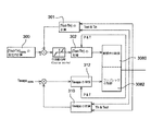
次に、図2の例による膨張弁12、及び外部制御コンプレッサの制御を示す、図4の機能系統図を参照する。この機能系統図は、パラメータTinをTminと、かつパラメータToutをTmaxと置き換えて、図3の実施例に同じように適用される。
Reference is now made to the functional system diagram of FIG. 4 showing the control of the
ステップ300で、制御ユニット40は、過熱に関する程度の設定(Tout−Tin)consを決定する。この設定は、過熱及び最適性能係数(COP)の間の関係を示す曲線に応じて決定される。この設定は、用いられる冷却流体に応じて変化する。R134A流体に関しては、それは、約12℃〜15℃である。
In
ステップ301で、制御ユニット40は、次に温度Tout及びTinの測定から、過熱に関する程度(Tout−Tin)を決定する。
In
ステップ302で、制御ユニットは、次にステップ301で決定された過熱に関する程度を、ステップ300で得られたその設定と比較する。膨張弁12の指令信号は、過熱に関する程度がその設定に達しない限り、次にステップ302(PID調節)で調整される。
In
それと並行して、制御ユニット40は、蒸発温度Tevapoを調節するように、コンプレッサ14を制御する。
In parallel, the
このようにして、ステップ301で、制御ユニット40は、温度Tout及びTinの測定から蒸発温度を決定する。
Thus, in
ステップ312で、制御ユニットは、次にステップ310で得られた蒸発温度の値Tevapoを、居住空間の制御盤によって提供されるその設定Tevapoconsと比較する。コンプレッサ14の指令信号は、過熱に関する程度が、その設定に達しない限り、次に、ステップ312(PID調節)で調整される。
In
第1の実施例において、制御ユニット40は、膨張弁12、及び必要な場合、コンプレッサ14を制御するために、コンプレッサ14の出口での冷却流体の送り出しパラメータの値を使用できる。装置は、そのために、コンデンサの入口での冷却流体の送り出し圧力Pr、及び送り出し温度Trを測定するために、コンプレッサ14の出口、又はコンデンサ11の入口に配置された温度及び圧力センサ20を備えている。センサ20によって提供されるこれらのパラメータの値Pr及びTrは、次に閾値と比較され、かつこの比較の結果に応じて、膨張弁12の作動、及び必要な場合、コンプレッサ14のそれが適応する。このようにして、例えば、制御ユニットは、センサ20によって測定された値が、そのそれぞれの閾値よりも大きいと決定されると、膨張弁12の開放を増加し、かつ膨張弁12の開放度が、所定の開放閾値よりも大きいと、コンプレッサ14の容量を減少させる。このことは、送り出しパラメータPr及びTrを許容可能なレベルに維持することを可能にする。
In the first embodiment, the
もう1つの例によれば、第1段階で、コンプレッサ14の排気量を減少させることが可能である。排気量が、決定された閾値に減少する時、膨張弁12の開放度を増加し始める。
According to another example, the displacement of the
従って本発明の第1の実施例は、膨張弁12、及び必要な場合、コンプレッサ14を制御するために、3つのセンサしか使用しない。
Thus, the first embodiment of the present invention uses only three sensors to control the
さらに、この第1の実施形による装置は、膨張弁12及びコンプレッサ14を制御するために、蒸発器13の出口で圧力センサを使用せず、そのため、装置のコストを減少させることができる。
Furthermore, the device according to this first embodiment does not use a pressure sensor at the outlet of the
第1の実施例は、内部交換器を備える空調回路10を備えていた。しかし、内部交換器を有しない空調回路にも同様に適用しうる。
The first embodiment includes an
次に、本発明の第2の実施例を示す図5〜図9を参照する。 Reference is now made to FIGS. 5-9 showing a second embodiment of the present invention.
この第2の実施例において、制御ユニット40は、選択された調節法則に応じて、膨張弁12の入口での過冷却に関する指令の程度を調節するように、膨張弁12の指令信号を制御する。膨張弁12の入口での過冷却の調節は、蒸発器13の出口での過熱に間接的に作用することを可能にする。
In this second embodiment, the
図5及び図6に示した例において、制御ユニットは、過冷却に関する程度のように、冷却流体の温度Tscを調節する。 In the example shown in FIGS. 5 and 6, the control unit adjusts the temperature Tsc of the cooling fluid as much as it relates to supercooling.
特に、図5の例において、冷却流体の過冷却温度Tscは、膨張弁12の入口での冷却流体の温度に対応する。
In particular, in the example of FIG. 5, the supercooling temperature Tsc of the cooling fluid corresponds to the temperature of the cooling fluid at the inlet of the
この温度は、膨張弁12の入口に置かれた温度プローブ29を使用して測定できる。
This temperature can be measured using a
制御ユニット40は、選択された調節法則、例えばPIDタイプの閉ループ調節法則に応じて、温度Tscを調節するように膨張弁12を制御する。そのために、制御ユニット40は、膨張弁12の入口での流体温度の設定Tscconsを決定し、次にセンサ29によって提供される温度Tscの測定、及び温度の設定Tscconsの間の偏差を減少させるように、膨張弁12の開放を制御する。Tscconsは、過冷却及び最適性能係数(COP)の間の関係に応じて決定される。Tscconsの制御は単純である。
The
その上、温度及び圧力センサ20は、第1の実施形と同じように、コンプレッサ14の出口で、補足で使用できる。
Moreover, the temperature and
図6の例において、冷却流体の過冷却温度Tscは、コンデンサ11の出口での冷却流体の温度に対応する。この温度は、コンデンサ11の出口に置かれる温度プローブ26を使用して測定できる。
In the example of FIG. 6, the supercooling temperature Tsc of the cooling fluid corresponds to the temperature of the cooling fluid at the outlet of the
制御ユニット40は、圧力が、センサ26によって測定された温度に対して、決定された法則、例えばPIDタイプの閉ループ調節法則と相関関係にあるために、センサ20によって測定された圧力を調節するように、膨張弁12を管理する。
The
図7及び図8は、制御ユニット40が、コンプレッサ14の吸い込み及び送り出し温度を限定するように、内部交換器の性能を更に制御するか、又は制御ユニット40が、過冷却に関する指令程度の調節の他に、冷却流体の質量流量Mcから内部交換器の性能を制御する、第2の実施例の簡略化された例を示す。
7 and 8 show that the
より正確には、図7の実施例において、制御ユニット40は、選択された調節法則に応じて冷却流体の高圧HPを調節するように膨張弁12を制御する。制御ユニット40は、膨張弁12の作動を更に調整するために、内部交換器9の効率EIHXを制御する。
More precisely, in the embodiment of FIG. 7, the
制御ユニット40は、選択された調節法則、例えばPIDタイプの閉ループ調節法則に応じて、高圧HPの測定をその設定値HPconsと比較し、高圧HPの調節を行い、かつこの比較の結果に応じて、電気膨張弁12に作用する。
The
この実施態様において、高圧HPの測定は、コンデンサ11の出口での冷却流体の圧力を提供する、コンデンサ11の出口に置かれたセンサ27により得られる。制御ユニット40は、コンデンサの出口での冷却流体の温度Tscの測定から、高圧の設定HPconsを計算する。この応用例において、冷却流体の温度Tsc及び圧力HPを同時に提供する、コンデンサ11の出口に置かれた単一の温度及び圧力センサ27を使用することを可能にするので、コンデンサ11の出口での温度Tscを同様に測定することが好適である。
In this embodiment, the high pressure HP measurement is obtained by a
過冷却SCは、次の式:
SC=Tsat(HP)−Tsc
(式中、冷却流体の飽和温度Tsatは、膨張弁12の入口での冷却流体の圧力HPによって決定される)に従って、冷却流体の飽和温度Tsat、及び減圧器の入口での温度Tscの間の差に対応する。
The supercooled SC is given by the following formula:
SC = Tsat (HP) -Tsc
(Where the saturation temperature Tsat of the cooling fluid is determined by the pressure HP of the cooling fluid at the inlet of the expansion valve 12), between the saturation temperature Tsat of the cooling fluid and the temperature Tsc at the inlet of the decompressor. Corresponds to the difference.
制御ユニット40は、選択された調節法則、例えばPIDタイプの閉ループ調節法則に応じて、過冷却の計算値SCをその設定値SCconsと比較し、過冷却SCの調節を行う。次に制御ユニット40は、この比較の結果に応じて、膨張弁12に作用する。
The
過冷却の値SCにより、冷却流体の過冷却温度Tscの測定、及び膨張弁12の入口での冷却流体の高圧HPの測定を行うように、コンデンサ11の出口に置かれたセンサ27により得られる。高圧の測定は、冷却流体の飽和温度Tsatを決定することを可能にする。
The supercooling value SC is obtained by a
図7及び図8の2つの実施例において、制御ユニット40は、内部交換器9の効率EIHXを、効率限界LIHXと比較して、内部交換器9の効率EIHXを補足的に調節できる。制御弁の作動は、効率EIHXが効率限界LIHXを超えることを、比較の結果が示す時に調整される。
7 and 8, the
膨張弁12を制御するために、内部交換器9の効率EIHXを考慮に入れることによって、過度に高いコンプレッサの送り出し温度からの保護を保証でき、かつコンプレッサの吸い込み圧力を限定できるようになる。そのために、内部交換器9の効率は、冷却流体の流量から評価される。
By taking into account the efficiency E IHX of the
図7の装置によれば、質量流量Mcは、コンデンサモデルから、従って測定がセンサ27によって提供される高圧HP、及び周囲温度の過冷却温度Tscから計算できる。
According to the apparatus of FIG. 7, the mass flow rate Mc can be calculated from the capacitor model, and thus from the high pressure HP whose measurement is provided by the
図8の実施例によれば、制御ユニット40は、コンプレッサ14の吸い込み及び送り出し温度を限定するために、冷却流体の過冷却及び内部交換器9の効率を調節するように、膨張弁12を管理する。
According to the embodiment of FIG. 8, the
図8の装置において、制御ユニット40は、冷却流体の質量流量Mcを計算して、内部交換器9の効率EIHXを評価できる。流量Mcは、例えば次の関係:
Mc=Kv.[2ρ.(HP−LP)]1/2
(式中、ρは、流体の密度であり、かつLPは、コンプレッサの制御法則に応じて評価できる低圧を表す)に応じて計算できる。
In the apparatus of FIG. 8, the
Mc = Kv. [2ρ. (HP-LP)] 1/2
Where ρ is the density of the fluid and LP represents the low pressure that can be evaluated according to the control law of the compressor.
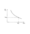
内部交換器9の効率の値EIHXは、次に冷却流体の質量流量の計算値Mcから、実験によって、又はシミュレーションによって評価できる。例えば、値EIHXは、図11と同じような図表を使用して決定できる。
The efficiency value E IHX of the
図11は、内部交換器の効率EIHXを、流体の流量Mcに結び付ける変化の法則例を示す。図11は、効率EIHXが、流体の流量Mcに応じて減少すること、及び所与の値Mc(0)に、曲線上の単一の値EIHX(0)が対応することを、特に示している。 FIG. 11 shows an example of the law of variation that links the efficiency E IHX of the internal exchanger to the fluid flow rate Mc. FIG. 11 shows that the efficiency E IHX decreases as a function of the fluid flow rate Mc and that a given value Mc (0) corresponds to a single value E IHX (0) on the curve. Show.
従って、制御ユニット40は、冷却流体の流量の計算値Mcから、かかる図表の内部交換器の効率EIHXの評価を引き出すことができる。
Therefore, the
図9は、空調回路が、内部交換器を備えない図8の簡略化した例を表す。 FIG. 9 represents the simplified example of FIG. 8 where the air conditioning circuit does not include an internal exchanger.
この例において、冷却流体の備蓄を確実に行い、減圧器に液体を補給するか、又は有害な酸及び異物粒子を除去するために、脱水槽16が、コンデンサ11の出口に設けることができる。
In this example, a dehydration tank 16 can be provided at the outlet of the
この例において、図7及び図8を参照して記載したように、過冷却SCの調節、又は圧力HPの調節を行うために、コンデンサ11の出口に、温度及びセンサ30を設けてある。内部交換器がないので、内部交換器の効率の補足調節、又はコンプレッサ14の出口での送り出し圧力、及び温度の調節を行うには及ばない。このようにして、この例では、2つのセンサ、すなわち、膨張弁12を制御するために使用される温度及び圧力センサ30、及びコンプレッサ14を制御するために使用される温度プローブ25しか存在しない。
In this example, as described with reference to FIGS. 7 and 8, the temperature and the
次に、図7の例による膨張弁12及び外部制御コンプレッサの制御を示す図10の機能系統図を参照する。
Reference is now made to the functional system diagram of FIG. 10 showing the control of the
ステップ322で、制御ユニット40は、ステップ320でセンサ27によって提供される温度Tscの測定から、過冷却に関する程度HPの設定HPconsを決定する。
In
ステップ324で、制御ユニット40は、センサ27の程度HPの測定を受ける。
In
ステップ326で、制御ユニットは、この測定HPを、ステップ322で得られたその設定HPconsと比較する。ステップ326(PID調節)で、膨張弁12の指令信号は、程度HPがその設定に達しない限り、次に調整される。
In
補足として、制御ユニット40は、内部交換器9の効率EIHXを効率限界LIHXと比較して、ステップ330で、内部交換器9の効率EIHXを制御する。ステップ328で、制御ユニット40は、コンデンサモデルによって流体の流量Mcを予め評価し、評価された流体の流量Mcから効率EIHXを評価し、かつ効率限界LIHXを決定する。制御弁の作動は、効率EIHXが効率限界LIHXを超えることを、比較の結果が示す時に調整される。
As a supplement, the
それと並行して、制御ユニット40は、蒸発温度Tevapoを調節するようにコンプレッサ14を制御する。制御ユニット40は、ステップ350で、蒸発温度の値Tevapoを、居住空間の制御盤によって提供されるその設定値Tevapoconsと比較する。コンプレッサ14の指令信号は、過熱に関する程度がその設定に達しない限り、次に調整される。
In parallel, the
図12の機能系統図は、図8の例による膨張弁12、及び外部制御コンプレッサの制御を示す。
The functional system diagram of FIG. 12 shows the control of the
この例において、ステップ340で、制御ユニット40は、試験又はシミュレーションの結果によって作成された表により、過冷却の設定SCconsを決定する。SCconsは、最適性能係数(COP)の最大に対応する。
In this example, at
ステップ342において、制御ユニット40は、次にセンサ28によって提供される、膨張弁12の入口での高圧HPの測定及び温度Tscの測定から、過冷却の値SCを計算する。
In
ステップ344で、制御ユニットは、次にこの値SCを、その設定SCconsと比較する。膨張弁12の指令信号は、過熱に関する程度がその設定に達しない限り、次に調整される。
In
制御ユニット40は、図7を参照して記載したように、内部交換器9の効率EIHX及びコンプレッサ14を補足で制御できる。
The
従って、本発明は、性能係数(COP)を最適化し、かつ空調回路内に最小数のセンサを使用して、電気膨張弁12及び必要な場合、外部制御コンプレッサ14を制御することを可能にする。特に、本発明は、蒸発器の出口での圧力センサの使用を回避すること、及びこのようにして装置のコストを減少させることを可能する。
Thus, the present invention allows optimizing the coefficient of performance (COP) and using a minimum number of sensors in the air conditioning circuit to control the
先に説明した種々の実施態様によれば、装置は、内部交換器を含んでいる。更に、記載された例では、コンデンサを内蔵する回路を取り上げた。しかしながら、本発明は、ガス冷却器を備えた回路も同様にカバーするものである。 According to various embodiments described above, the apparatus includes an internal exchanger. Furthermore, in the described example, a circuit incorporating a capacitor is taken up. However, the present invention covers a circuit with a gas cooler as well.
このように、本発明は、例として先に記載された実施態様に限定されず、かつ内部交換器を有しないか、又はガス冷却器を備える装置をも同様にカバーする。 Thus, the present invention is not limited to the embodiment described above by way of example, and covers devices that do not have an internal exchanger or that comprise a gas cooler as well.
9 内部熱交換器
10 空調回路
11 コンデンサ
12 膨張装置
13 蒸発器
14 コンプレッサ
16 脱水槽
18 ボンベ
20 センサ
21 センサ
22 センサ
23 センサ
24 センサ
25 センサ
26 センサ
27 センサ
28 センサ
29 センサ
30 センサ
40 制御ユニット
100 空調装置
DESCRIPTION OF
Claims (25)
コンデンサ(11)又はガス冷却器と、A condenser (11) or a gas cooler;
開放度が指令信号に応じて変化する電気膨張弁(12)と、An electric expansion valve (12) whose opening degree changes according to the command signal;
蒸発器(13)と、An evaporator (13);
前記コンプレッサ(14)を循環する冷却流体と、A cooling fluid circulating in the compressor (14);
前記蒸発器(13)から前記コンプレッサ(14)に循環する前記冷却流体を用いて熱の交換をするために、前記コンデンサ(11)又は前記ガス冷却器から前記電気膨張弁(12)に前記冷却流体を循環させる内部交換器(9)In order to exchange heat using the cooling fluid circulating from the evaporator (13) to the compressor (14), the cooling from the condenser (11) or the gas cooler to the electric expansion valve (12). Internal exchanger for circulating fluid (9)
とを含む空調回路を備える自動車用の空調装置であって、An air conditioner for an automobile including an air conditioning circuit including:
前記コンプレッサ(14)の出口、及び/又は前記コンデンサ(11)又は前記ガス冷却器の入口での温度と圧力を測定するために、前記コンプレッサ(14)の出口、及び/又は前記コンデンサ(11)又は前記ガス冷却器の入口に配置された前記温度及び圧力センサ(20)と、In order to measure the temperature and pressure at the outlet of the compressor (14) and / or the condenser (11) or the inlet of the gas cooler, the outlet of the compressor (14) and / or the condenser (11) Or the temperature and pressure sensor (20) located at the inlet of the gas cooler;
選択された調節法則に応じて前記蒸発器(13)の過熱又は前記コンデンサ(11)の過冷却に関する指令の程度を調節するために、および前記内部交換器(9)の効率を制御するために、前記温度及び前記圧力センサ(20)によって測定された温度及び圧力の測定値に基づいて前記電気膨張弁(12)に対する前記指令信号を生成する制御ユニット(40)To adjust the degree of command for overheating of the evaporator (13) or subcooling of the condenser (11) according to the selected regulation law and to control the efficiency of the internal exchanger (9) A control unit (40) for generating the command signal for the electric expansion valve (12) based on temperature and pressure measurements measured by the temperature and pressure sensor (20)
とを更に備えることを特徴とする空調装置。And an air conditioner.
前記コンプレッサ(14)の出口、及び/又は前記コンデンサ(11)又は前記ガス冷却器の入口に配置された前記温度及び圧力センサ(20)は、前記コンプレッサ(14)の出口、及び/又は前記コンデンサ(11)又は前記ガス冷却器の入口での温度と圧力を測定し、制御ユニット(40)は、選択された調節法則に応じて前記蒸発器(13)の過熱又は前記コンデンサ(11)の過冷却に関する指令の程度を調節するために、および前記内部交換器(9)の効率を制御するために、前記温度及び前記圧力センサ(20)によって測定された温度及び圧力の測定値に基づいて前記電気膨張弁(12)に対する前記指令信号を生成することを特徴とする方法。The temperature and pressure sensor (20) located at the outlet of the compressor (14) and / or the condenser (11) or the inlet of the gas cooler is connected to the outlet of the compressor (14) and / or the condenser. (11) or the temperature and pressure at the inlet of the gas cooler, and the control unit (40) determines whether the evaporator (13) is overheated or the condenser (11) is overheated according to the selected regulation law. Based on the temperature and pressure measurements measured by the temperature and the pressure sensor (20) to adjust the degree of cooling commands and to control the efficiency of the internal exchanger (9). Generating the command signal for the electric expansion valve (12).
Applications Claiming Priority (2)
| Application Number | Priority Date | Filing Date | Title |
|---|---|---|---|
| FR0701445 | 2007-02-28 | ||
| FR0701445A FR2913102B1 (en) | 2007-02-28 | 2007-02-28 | AIR CONDITIONING INSTALLATION EQUIPPED WITH AN ELECTRICAL RELIEF VALVE |
Publications (2)
| Publication Number | Publication Date |
|---|---|
| JP2008213830A JP2008213830A (en) | 2008-09-18 |
| JP5543689B2 true JP5543689B2 (en) | 2014-07-09 |
Family
ID=38658719
Family Applications (1)
| Application Number | Title | Priority Date | Filing Date |
|---|---|---|---|
| JP2008047991A Expired - Fee Related JP5543689B2 (en) | 2007-02-28 | 2008-02-28 | Air conditioner with electric expansion valve |
Country Status (4)
| Country | Link |
|---|---|
| US (1) | US9341398B2 (en) |
| EP (1) | EP1965156B1 (en) |
| JP (1) | JP5543689B2 (en) |
| FR (1) | FR2913102B1 (en) |
Families Citing this family (25)
| Publication number | Priority date | Publication date | Assignee | Title |
|---|---|---|---|---|
| US8100582B1 (en) * | 2007-12-13 | 2012-01-24 | Powell Bradley J | Temperature probe |
| FR2928445B1 (en) * | 2008-03-06 | 2014-01-03 | Valeo Systemes Thermiques Branche Thermique Habitacle | METHOD FOR CONTROLLING A RELIEF UNIT COMPRISING AN AIR CONDITIONING LOOP OF A VENTILATION, HEATING AND / OR AIR CONDITIONING INSTALLATION OF A VEHICLE |
| CN102165194B (en) * | 2008-09-26 | 2015-11-25 | 开利公司 | Compressor discharge on transport refrigeration system controls |
| WO2011022267A2 (en) | 2009-08-17 | 2011-02-24 | Microstaq, Inc. | Micromachined device and control method |
| JP2011069570A (en) * | 2009-09-28 | 2011-04-07 | Fujitsu General Ltd | Heat pump cycle device |
| JP2011094810A (en) * | 2009-09-30 | 2011-05-12 | Fujitsu General Ltd | Heat pump cycle apparatus |
| CN102792419B (en) | 2010-01-28 | 2015-08-05 | 盾安美斯泰克股份有限公司 | The technique that high temperature selective fusion engages and structure |
| US8956884B2 (en) | 2010-01-28 | 2015-02-17 | Dunan Microstaq, Inc. | Process for reconditioning semiconductor surface to facilitate bonding |
| US8996141B1 (en) | 2010-08-26 | 2015-03-31 | Dunan Microstaq, Inc. | Adaptive predictive functional controller |
| FR2964450B1 (en) * | 2010-09-02 | 2012-10-19 | Valeo Systemes Thermiques | METHOD FOR CONTROLLING A RELIEF VALVE |
| US9328945B2 (en) | 2010-10-06 | 2016-05-03 | Nissan Motor Co., Ltd. | Air conditioner for vehicle |
| FR2984471B1 (en) * | 2011-12-15 | 2013-11-29 | Valeo Systemes Thermiques | DEVICE FOR THERMALLY CONDITIONING A TRACTION CHAIN AND A VEHICLE HABITACLE |
| US8925793B2 (en) | 2012-01-05 | 2015-01-06 | Dunan Microstaq, Inc. | Method for making a solder joint |
| US9140613B2 (en) | 2012-03-16 | 2015-09-22 | Zhejiang Dunan Hetian Metal Co., Ltd. | Superheat sensor |
| DE102012212863B4 (en) * | 2012-06-15 | 2019-10-31 | Bayerische Motoren Werke Aktiengesellschaft | Vehicle with a heat pump cycle |
| KR101919846B1 (en) * | 2013-07-18 | 2018-11-19 | 항저우 산후아 리서치 인스티튜트 컴퍼니 리미티드 | Method for controlling degree of superheat of vehicle air-conditioning system, and vehicle air-conditioning system |
| KR101827182B1 (en) * | 2013-07-18 | 2018-02-07 | 항저우 산후아 리서치 인스티튜트 컴퍼니 리미티드 | Method for controlling vehicle air-conditioning system, and vehicle air-conditioning system |
| US9188375B2 (en) | 2013-12-04 | 2015-11-17 | Zhejiang Dunan Hetian Metal Co., Ltd. | Control element and check valve assembly |
| ES2638600T3 (en) * | 2014-01-29 | 2017-10-23 | Fujitsu General Limited | Heat pump type device for heating and supplying hot water |
| US9983083B2 (en) * | 2014-10-16 | 2018-05-29 | Trensor, LLC | Climate control pressure plug with sensor |
| FR3069625B1 (en) * | 2017-07-28 | 2019-12-27 | Valeo Systemes Thermiques | METHOD FOR MANAGING AN INVERSIBLE MOTOR VEHICLE AIR CONDITIONING CIRCUIT |
| FR3069626B1 (en) * | 2017-07-28 | 2019-12-27 | Valeo Systemes Thermiques | METHOD FOR MANAGING A MOTOR VEHICLE AIR CONDITIONING CIRCUIT |
| CN108731324B (en) * | 2018-06-22 | 2020-12-25 | 江苏新安电器有限公司 | Superheat degree controlled electronic expansion valve system |
| US20210333028A1 (en) * | 2019-07-10 | 2021-10-28 | Ecoer Inc | Refrigerant charging system and method for variable speed compressor based ac system |
| WO2021050886A1 (en) * | 2019-09-12 | 2021-03-18 | Carrier Corporation | Dual temperature sensor arrangement to detect refrigerant leak |
Family Cites Families (42)
| Publication number | Priority date | Publication date | Assignee | Title |
|---|---|---|---|---|
| DE2451361A1 (en) * | 1974-10-29 | 1976-05-06 | Jakob | Coolant circulation in refrigerator of cold-storage plant - controlled drive-motor speeds maintain constant temperature at expansion valve |
| FR2539855B1 (en) * | 1983-01-25 | 1985-09-27 | Comp Generale Electricite | METHOD AND DEVICE FOR ADJUSTING THE EXPANSION RATE IN A VALVE FOR EXPANSION OF THE REFRIGERANT FLUID OF A HEAT PUMP CYCLE |
| US5502970A (en) * | 1995-05-05 | 1996-04-02 | Copeland Corporation | Refrigeration control using fluctuating superheat |
| JP3063574B2 (en) * | 1995-06-26 | 2000-07-12 | 株式会社デンソー | Air conditioner |
| JP3467989B2 (en) * | 1996-09-13 | 2003-11-17 | 株式会社日本自動車部品総合研究所 | Vapor compression refrigeration cycle |
| EP0837291B1 (en) * | 1996-08-22 | 2005-01-12 | Denso Corporation | Vapor compression type refrigerating system |
| JP4134399B2 (en) * | 1997-11-28 | 2008-08-20 | 株式会社デンソー | Refrigeration cycle controller |
| JP3327215B2 (en) * | 1998-07-22 | 2002-09-24 | 三菱電機株式会社 | Method for determining refrigerant charge of air conditioner |
| JP3094997B2 (en) * | 1998-09-30 | 2000-10-03 | ダイキン工業株式会社 | Refrigeration equipment |
| JP2000111182A (en) * | 1998-10-09 | 2000-04-18 | Sanden Corp | Air conditioner |
| JP2000146322A (en) * | 1998-11-16 | 2000-05-26 | Zexel Corp | Refrigerating cycle |
| JP4348572B2 (en) * | 1999-01-27 | 2009-10-21 | 株式会社ヴァレオサーマルシステムズ | Refrigeration cycle |
| JP2000272335A (en) * | 1999-03-23 | 2000-10-03 | Sanden Corp | Air conditioner for vehicle |
| US6148628A (en) * | 1999-03-26 | 2000-11-21 | Carrier Corporation | Electronic expansion valve without pressure sensor reading |
| US6141981A (en) * | 1999-03-26 | 2000-11-07 | Carrier Corporation | Superheat control for optimum capacity under power limitation and using a suction modulation valve |
| JP2001027455A (en) * | 1999-05-13 | 2001-01-30 | Denso Corp | Heat pump air conditioner |
| DE60037445T2 (en) * | 1999-10-18 | 2008-12-04 | Daikin Industries, Ltd. | COOLING DEVICE |
| US6260368B1 (en) * | 2000-01-10 | 2001-07-17 | Robert Walter Redlich | Evaporator superheat stabilizer |
| US6321549B1 (en) * | 2000-04-14 | 2001-11-27 | Carrier Corporation | Electronic expansion valve control system |
| US6318100B1 (en) * | 2000-04-14 | 2001-11-20 | Carrier Corporation | Integrated electronic refrigerant management system |
| CN1220004C (en) * | 2000-06-07 | 2005-09-21 | 三星电子株式会社 | Control system of degree of superheat of air conditioner and ocntrol method thereof |
| JP3838008B2 (en) * | 2000-09-06 | 2006-10-25 | 松下電器産業株式会社 | Refrigeration cycle equipment |
| FR2815397B1 (en) * | 2000-10-12 | 2004-06-25 | Valeo Climatisation | VEHICLE AIR CONDITIONING DEVICE USING A SUPERCRITICAL CYCLE |
| JP2002130849A (en) * | 2000-10-30 | 2002-05-09 | Calsonic Kansei Corp | Cooling cycle and its control method |
| US6625029B2 (en) * | 2000-11-06 | 2003-09-23 | Skg Italiana Spa | Sensor unit |
| FR2841828B1 (en) * | 2002-07-02 | 2004-08-27 | Valeo Climatisation | AIR CONDITIONING SYSTEM FOR A MOTOR VEHICLE, PROVIDED WITH AN ELECTRONIC CONTROL DEVICE |
| US6973793B2 (en) * | 2002-07-08 | 2005-12-13 | Field Diagnostic Services, Inc. | Estimating evaporator airflow in vapor compression cycle cooling equipment |
| JP2004061061A (en) * | 2002-07-31 | 2004-02-26 | Matsushita Electric Ind Co Ltd | Freezing cycle device and its operation method |
| FR2845035B1 (en) * | 2002-09-27 | 2004-12-24 | Valeo Climatisation | AIR CONDITIONING SYSTEM COMPRISING AN ELECTRONIC CONTROL DEVICE |
| ITTO20030792A1 (en) * | 2002-10-08 | 2004-04-09 | Danfoss As | VALVE CONTROL DEVICE AND PROCEDURE |
| FR2856782B1 (en) * | 2003-06-30 | 2005-09-23 | Valeo Climatisation | AIR CONDITIONING INSTALLATION OF A VEHICLE OPERATING ACCORDING TO A SUPERCRITICAL CYCLE |
| KR100540808B1 (en) * | 2003-10-17 | 2006-01-10 | 엘지전자 주식회사 | Control method for Superheating of heat pump system |
| FR2862573B1 (en) * | 2003-11-25 | 2006-01-13 | Valeo Climatisation | AIR CONDITIONING INSTALLATION OF VEHICLE |
| DE102004010997B3 (en) * | 2004-03-03 | 2005-06-23 | Otto Egelhof Gmbh & Co. Kg | Control method for expansion valve for refrigeration medium circuit in automobile air-conditioning installation using pressure difference between input and output of expansion valve |
| US20060112702A1 (en) * | 2004-05-18 | 2006-06-01 | George Martin | Energy efficient capacity control for an air conditioning system |
| US7380404B2 (en) * | 2005-01-05 | 2008-06-03 | Carrier Corporation | Method and control for determining low refrigerant charge |
| CN100520225C (en) * | 2005-02-18 | 2009-07-29 | 卡里尔公司 | Method for controlling high-pressure in an intermittently supercritically operating refrigeration circuit |
| US7631510B2 (en) * | 2005-02-28 | 2009-12-15 | Thermal Analysis Partners, LLC. | Multi-stage refrigeration system including sub-cycle control characteristics |
| JP2006266533A (en) * | 2005-03-22 | 2006-10-05 | Fuji Koki Corp | Valve control system and valve control method |
| DE102006029973B4 (en) * | 2005-06-30 | 2016-07-28 | Denso Corporation | ejector cycle |
| JP2007139269A (en) * | 2005-11-16 | 2007-06-07 | Denso Corp | Supercritical refrigerating cycle |
| US7467891B2 (en) * | 2005-11-29 | 2008-12-23 | Sensata Technologies, Inc. | Sensor arrangement for measuring a pressure and a temperature in a fluid |
-
2007
- 2007-02-28 FR FR0701445A patent/FR2913102B1/en not_active Expired - Fee Related
-
2008
- 2008-01-16 EP EP08100554.8A patent/EP1965156B1/en active Active
- 2008-02-28 US US12/038,848 patent/US9341398B2/en active Active
- 2008-02-28 JP JP2008047991A patent/JP5543689B2/en not_active Expired - Fee Related
Also Published As
| Publication number | Publication date |
|---|---|
| EP1965156B1 (en) | 2020-04-08 |
| JP2008213830A (en) | 2008-09-18 |
| FR2913102A1 (en) | 2008-08-29 |
| US20080229770A1 (en) | 2008-09-25 |
| EP1965156A1 (en) | 2008-09-03 |
| US9341398B2 (en) | 2016-05-17 |
| FR2913102B1 (en) | 2012-11-16 |
Similar Documents
| Publication | Publication Date | Title |
|---|---|---|
| JP5543689B2 (en) | Air conditioner with electric expansion valve | |
| EP2588818B1 (en) | A method for operating a vapour compression system using a subcooling value | |
| EP2224191B1 (en) | Air conditioner and method of controlling the same | |
| US8353173B2 (en) | Refrigerating cycle apparatus and operation control method therefor | |
| US8082752B2 (en) | Pressure-reducing module for dual evaporator air conditioning system | |
| CA2962829C (en) | A method for operating a vapour compression system with a receiver | |
| JP5981376B2 (en) | Air conditioner and method of operating air conditioner | |
| US9970696B2 (en) | Defrost for transcritical vapor compression system | |
| JP5046895B2 (en) | Air conditioner and operation control method thereof | |
| US7997093B2 (en) | Air conditioner | |
| CN103673416A (en) | Control method for refrigerant flow quantity in automobile air conditioning system and automobile air conditioning system | |
| US10876777B2 (en) | Air conditioning device using vapor injection cycle and method for controlling the device | |
| US6817193B2 (en) | Method for operating a refrigerant circuit, method for operating a motor vehicle driving engine, and refrigerant circuit | |
| KR101296064B1 (en) | Air conditioner and control method thereof | |
| US20120073316A1 (en) | Control of a transcritical vapor compression system | |
| WO2010118745A2 (en) | A method of controlling operation of a vapour compression system | |
| CN112513542B (en) | Method for controlling a vapor compression system based on a predicted flow | |
| KR101233865B1 (en) | Air conditioner and control method thereof | |
| JP6590768B2 (en) | Air conditioner | |
| KR101321543B1 (en) | Air conditioning system | |
| KR101450545B1 (en) | Air conditioning system | |
| CN107003053B (en) | For controlling the method including calculating reference temperature for arriving the cold-producing medium supply of evaporator | |
| JP6348048B2 (en) | Refrigeration cycle equipment | |
| KR100764941B1 (en) | An Airconditioner For Vehicle And Control Method Thereof | |
| KR100860032B1 (en) | Method of controlling air conditioning system |
Legal Events
| Date | Code | Title | Description |
|---|---|---|---|
| A621 | Written request for application examination |
Free format text: JAPANESE INTERMEDIATE CODE: A621 Effective date: 20110118 |
|
| A977 | Report on retrieval |
Free format text: JAPANESE INTERMEDIATE CODE: A971007 Effective date: 20120621 |
|
| A131 | Notification of reasons for refusal |
Free format text: JAPANESE INTERMEDIATE CODE: A131 Effective date: 20120626 |
|
| A601 | Written request for extension of time |
Free format text: JAPANESE INTERMEDIATE CODE: A601 Effective date: 20120924 |
|
| A602 | Written permission of extension of time |
Free format text: JAPANESE INTERMEDIATE CODE: A602 Effective date: 20120927 |
|
| A601 | Written request for extension of time |
Free format text: JAPANESE INTERMEDIATE CODE: A601 Effective date: 20121025 |
|
| A602 | Written permission of extension of time |
Free format text: JAPANESE INTERMEDIATE CODE: A602 Effective date: 20121030 |
|
| A601 | Written request for extension of time |
Free format text: JAPANESE INTERMEDIATE CODE: A601 Effective date: 20121122 |
|
| A602 | Written permission of extension of time |
Free format text: JAPANESE INTERMEDIATE CODE: A602 Effective date: 20121128 |
|
| A521 | Request for written amendment filed |
Free format text: JAPANESE INTERMEDIATE CODE: A523 Effective date: 20121221 |
|
| A131 | Notification of reasons for refusal |
Free format text: JAPANESE INTERMEDIATE CODE: A131 Effective date: 20130702 |
|
| A601 | Written request for extension of time |
Free format text: JAPANESE INTERMEDIATE CODE: A601 Effective date: 20131001 |
|
| A602 | Written permission of extension of time |
Free format text: JAPANESE INTERMEDIATE CODE: A602 Effective date: 20131004 |
|
| A601 | Written request for extension of time |
Free format text: JAPANESE INTERMEDIATE CODE: A601 Effective date: 20131101 |
|
| A602 | Written permission of extension of time |
Free format text: JAPANESE INTERMEDIATE CODE: A602 Effective date: 20131107 |
|
| A521 | Request for written amendment filed |
Free format text: JAPANESE INTERMEDIATE CODE: A523 Effective date: 20131202 |
|
| TRDD | Decision of grant or rejection written | ||
| A01 | Written decision to grant a patent or to grant a registration (utility model) |
Free format text: JAPANESE INTERMEDIATE CODE: A01 Effective date: 20140311 |
|
| A601 | Written request for extension of time |
Free format text: JAPANESE INTERMEDIATE CODE: A601 Effective date: 20140410 |
|
| A602 | Written permission of extension of time |
Free format text: JAPANESE INTERMEDIATE CODE: A602 Effective date: 20140416 |
|
| A61 | First payment of annual fees (during grant procedure) |
Free format text: JAPANESE INTERMEDIATE CODE: A61 Effective date: 20140509 |
|
| R150 | Certificate of patent or registration of utility model |
Ref document number: 5543689 Country of ref document: JP Free format text: JAPANESE INTERMEDIATE CODE: R150 |
|
| R250 | Receipt of annual fees |
Free format text: JAPANESE INTERMEDIATE CODE: R250 |
|
| R250 | Receipt of annual fees |
Free format text: JAPANESE INTERMEDIATE CODE: R250 |
|
| R250 | Receipt of annual fees |
Free format text: JAPANESE INTERMEDIATE CODE: R250 |
|
| R250 | Receipt of annual fees |
Free format text: JAPANESE INTERMEDIATE CODE: R250 |
|
| R250 | Receipt of annual fees |
Free format text: JAPANESE INTERMEDIATE CODE: R250 |
|
| R250 | Receipt of annual fees |
Free format text: JAPANESE INTERMEDIATE CODE: R250 |
|
| LAPS | Cancellation because of no payment of annual fees |