JP5543481B2 - Expansion valve with diaphragm and at least two outlet openings - Google Patents
Expansion valve with diaphragm and at least two outlet openings Download PDFInfo
- Publication number
- JP5543481B2 JP5543481B2 JP2011536740A JP2011536740A JP5543481B2 JP 5543481 B2 JP5543481 B2 JP 5543481B2 JP 2011536740 A JP2011536740 A JP 2011536740A JP 2011536740 A JP2011536740 A JP 2011536740A JP 5543481 B2 JP5543481 B2 JP 5543481B2
- Authority
- JP
- Japan
- Prior art keywords
- diaphragm
- valve
- expansion valve
- valve seat
- expansion
- Prior art date
- Legal status (The legal status is an assumption and is not a legal conclusion. Google has not performed a legal analysis and makes no representation as to the accuracy of the status listed.)
- Expired - Fee Related
Links
Images


Classifications
-
- F—MECHANICAL ENGINEERING; LIGHTING; HEATING; WEAPONS; BLASTING
- F25—REFRIGERATION OR COOLING; COMBINED HEATING AND REFRIGERATION SYSTEMS; HEAT PUMP SYSTEMS; MANUFACTURE OR STORAGE OF ICE; LIQUEFACTION SOLIDIFICATION OF GASES
- F25B—REFRIGERATION MACHINES, PLANTS OR SYSTEMS; COMBINED HEATING AND REFRIGERATION SYSTEMS; HEAT PUMP SYSTEMS
- F25B5/00—Compression machines, plants or systems, with several evaporator circuits, e.g. for varying refrigerating capacity
- F25B5/02—Compression machines, plants or systems, with several evaporator circuits, e.g. for varying refrigerating capacity arranged in parallel
-
- F—MECHANICAL ENGINEERING; LIGHTING; HEATING; WEAPONS; BLASTING
- F25—REFRIGERATION OR COOLING; COMBINED HEATING AND REFRIGERATION SYSTEMS; HEAT PUMP SYSTEMS; MANUFACTURE OR STORAGE OF ICE; LIQUEFACTION SOLIDIFICATION OF GASES
- F25B—REFRIGERATION MACHINES, PLANTS OR SYSTEMS; COMBINED HEATING AND REFRIGERATION SYSTEMS; HEAT PUMP SYSTEMS
- F25B41/00—Fluid-circulation arrangements
- F25B41/30—Expansion means; Dispositions thereof
- F25B41/31—Expansion valves
- F25B41/33—Expansion valves with the valve member being actuated by the fluid pressure, e.g. by the pressure of the refrigerant
- F25B41/335—Expansion valves with the valve member being actuated by the fluid pressure, e.g. by the pressure of the refrigerant via diaphragms
-
- F—MECHANICAL ENGINEERING; LIGHTING; HEATING; WEAPONS; BLASTING
- F25—REFRIGERATION OR COOLING; COMBINED HEATING AND REFRIGERATION SYSTEMS; HEAT PUMP SYSTEMS; MANUFACTURE OR STORAGE OF ICE; LIQUEFACTION SOLIDIFICATION OF GASES
- F25B—REFRIGERATION MACHINES, PLANTS OR SYSTEMS; COMBINED HEATING AND REFRIGERATION SYSTEMS; HEAT PUMP SYSTEMS
- F25B41/00—Fluid-circulation arrangements
- F25B41/30—Expansion means; Dispositions thereof
- F25B41/385—Dispositions with two or more expansion means arranged in parallel on a refrigerant line leading to the same evaporator
-
- F—MECHANICAL ENGINEERING; LIGHTING; HEATING; WEAPONS; BLASTING
- F25—REFRIGERATION OR COOLING; COMBINED HEATING AND REFRIGERATION SYSTEMS; HEAT PUMP SYSTEMS; MANUFACTURE OR STORAGE OF ICE; LIQUEFACTION SOLIDIFICATION OF GASES
- F25B—REFRIGERATION MACHINES, PLANTS OR SYSTEMS; COMBINED HEATING AND REFRIGERATION SYSTEMS; HEAT PUMP SYSTEMS
- F25B2600/00—Control issues
- F25B2600/25—Control of valves
- F25B2600/2511—Evaporator distribution valves
-
- Y—GENERAL TAGGING OF NEW TECHNOLOGICAL DEVELOPMENTS; GENERAL TAGGING OF CROSS-SECTIONAL TECHNOLOGIES SPANNING OVER SEVERAL SECTIONS OF THE IPC; TECHNICAL SUBJECTS COVERED BY FORMER USPC CROSS-REFERENCE ART COLLECTIONS [XRACs] AND DIGESTS
- Y10—TECHNICAL SUBJECTS COVERED BY FORMER USPC
- Y10T—TECHNICAL SUBJECTS COVERED BY FORMER US CLASSIFICATION
- Y10T137/00—Fluid handling
- Y10T137/7722—Line condition change responsive valves
- Y10T137/7737—Thermal responsive
Description
本発明は、例えば空気調和システム、特に冷凍システム用の膨張弁に関する。本発明の膨張弁は、例えば少なくとも2つの並列する蒸発器または蒸発器管の形態の、少なくとも2つの並列流路に流体媒体を分配するべく適応されている。 The present invention relates to an expansion valve for an air conditioning system, in particular a refrigeration system. The expansion valve of the present invention is adapted to distribute the fluid medium to at least two parallel flow paths, for example in the form of at least two parallel evaporators or evaporator tubes.
冷凍システムの冷凍回路のような流体回路において、流路を流体回路の部分に沿って2以上の並列流路に分割することが時として望ましい。これは例えば、並列して配置された2以上の蒸発器を備える冷凍システムの場合である。さらに、例えばほぼ等しい流体分配が得られるようにして、または例えばエネルギー消費または効率に関して最適の様態でシステムが操作されるようにして、並列流路の各々への流体流れを制御できることが望ましいこともある。 In a fluid circuit, such as a refrigeration circuit of a refrigeration system, it is sometimes desirable to divide the flow path into two or more parallel flow paths along a portion of the fluid circuit. This is the case, for example, for a refrigeration system comprising two or more evaporators arranged in parallel. In addition, it may be desirable to be able to control the fluid flow to each of the parallel flow paths, for example, so that approximately equal fluid distribution is obtained, or the system is operated in an optimal manner, for example with respect to energy consumption or efficiency. is there.
冷媒の分配を冷凍システムの2以上の並列流路間で制御するいくつかの従前の試みでは、分流器が冷媒流路で膨張弁に対して下流に配置される。従って、冷媒は冷媒の膨張の後に分配される、すなわち冷媒は主に気体である。これは、並列流路間でほぼ等しい分配を得るために冷媒の流れを制御することが極めて難しいという短所を有する。 In some previous attempts to control refrigerant distribution between two or more parallel flow paths of a refrigeration system, a shunt is placed downstream of the expansion valve in the refrigerant flow path. Thus, the refrigerant is distributed after the expansion of the refrigerant, i.e. the refrigerant is mainly gaseous. This has the disadvantage that it is extremely difficult to control the flow of the refrigerant in order to obtain approximately equal distribution between the parallel flow paths.
本発明の実施形態の目的は、2以上の並列流路への流体の分配を制御できる膨張弁を提供することである。 An object of an embodiment of the present invention is to provide an expansion valve that can control the distribution of fluid to two or more parallel flow paths.
本発明の実施形態のさらなる目的は、2以上の並列流路への流体の分配を容易な様態で管理するべく適応された膨張弁を提供することである。 A further object of an embodiment of the present invention is to provide an expansion valve adapted to manage the distribution of fluid to two or more parallel flow paths in an easy manner.
本発明によれば、第1の態様として提供される膨張弁は、
液体状態の流体媒体を受け入るよう構成された入口開口を備え、
少なくとも2つの出口開口を備え、各々は少なくとも部分的に気体状態の流体媒体を供給するよう構成されており、
ダイヤフラムを備え、
少なくとも2つの弁座を備え、
各弁座は出口開口の1つと流体接続されており、弁座の各々はダイヤフラムとの組合せで弁を形成しており、それによってダイヤフラムの位置が同時に弁の各々の開度を規定する。
According to the present invention, the expansion valve provided as the first aspect is
An inlet opening configured to receive a fluid medium in a liquid state;
Comprising at least two outlet openings, each configured to supply at least partially a gaseous fluid medium;
With a diaphragm,
Comprising at least two valve seats,
Each valve seat is fluidly connected to one of the outlet openings, each of which forms a valve in combination with a diaphragm, whereby the position of the diaphragm simultaneously defines the opening of each of the valves.
本発明の膨張弁は、入口開口と少なくとも2つの出口開口との間に流路を規定する。液体状態の流体媒体が入口開口に受け入れられ、少なくとも部分的に気体状態の流体媒体が出口開口で供給される。本件の文脈において、用語「液体状態」は、入口開口を通じて膨張弁に入る流体媒体がほぼ液相であることを意味すると解釈しなければならない。同様に、本件の文脈において、用語「少なくとも部分的に気体状態」は、出口開口を通じて膨張弁を出る流体媒体が完全に気相であるか、または膨張弁を出る流体媒体の量の少なくとも1部が、例えば相当部分が、気相であることを意味すると解釈しなければならない。従って、膨張弁に入る流体媒体の少なくとも一部は、膨張弁を通過する際に液相から気相への相転移を受ける。 The expansion valve of the present invention defines a flow path between the inlet opening and the at least two outlet openings. A liquid fluid medium is received in the inlet opening and an at least partially gaseous fluid medium is supplied at the outlet opening. In the present context, the term “liquid state” should be taken to mean that the fluid medium entering the expansion valve through the inlet opening is substantially in the liquid phase. Similarly, in the present context, the term “at least partially in the gaseous state” means that the fluid medium exiting the expansion valve through the outlet opening is completely in the gas phase or at least a portion of the amount of fluid medium exiting the expansion valve. Should be interpreted to mean, for example, that a substantial part is in the gas phase. Accordingly, at least a portion of the fluid medium entering the expansion valve undergoes a phase transition from liquid to gas phase as it passes through the expansion valve.
入口開口および出口開口は好ましくは、冷凍システムの他の構成要素のような1以上の他の構成要素と流体接続され得る。膨張弁は、流れ回路のような流れシステムの一部を有利に形成し得る。 The inlet opening and outlet opening may preferably be fluidly connected to one or more other components, such as other components of the refrigeration system. The expansion valve can advantageously form part of a flow system, such as a flow circuit.
膨張弁は、ダイヤフラムおよび少なくとも2つの弁座を備える。各弁座は出口開口の1つと流体接続されている。ダイヤフラムおよび弁座は、各弁座とダイヤフラムとの組合せで弁が形成されるように、相互に配置される。弁座の各々が出口開口の1つと流体接続されているので、弁座およびダイヤフラムによって形成される弁は、出口開口の各々に向かう流体流れを規定する。 The expansion valve includes a diaphragm and at least two valve seats. Each valve seat is fluidly connected to one of the outlet openings. The diaphragm and the valve seat are arranged with each other so that a valve is formed by a combination of each valve seat and the diaphragm. Since each of the valve seats is fluidly connected to one of the outlet openings, the valve formed by the valve seat and diaphragm defines a fluid flow toward each of the outlet openings.
弁は、弁座と、ダイヤフラムの特定の部分または領域(例えばダイヤフラムに取り付けられたバルブコーンまたは弁板の形態)とによって形成され得る、ことに留意しなければならない。 It should be noted that the valve may be formed by a valve seat and a particular portion or region of the diaphragm (eg, in the form of a valve cone or valve plate attached to the diaphragm).
従って、ダイヤフラムが動かされると、それは同時に弁座の各々に対する相対運動を実行し、それによって同時に弁座およびダイヤフラムによって形成される弁の各々の開度を変える。このようにして、開度は同期して調整され、それによって出口開口間の分配キーを少なくとも実質的に維持する。さらに、これは少なくとも2つの出口開口に向かう流体流れを同時に制御する極めて単純な方法である。最後に、並列流路間での流体媒体の分配は、分配が膨張弁において生じるので、流体媒体の膨張の前またはその間に生じる。これは流体分配を正確に制御するのをより容易にする。 Thus, when the diaphragm is moved, it simultaneously performs relative movement with respect to each of the valve seats, thereby simultaneously changing the opening of each of the valves formed by the valve seat and the diaphragm. In this way, the opening is adjusted synchronously, thereby at least substantially maintaining the distribution key between the outlet openings. Furthermore, this is a very simple way of controlling the fluid flow towards at least two outlet openings simultaneously. Finally, the distribution of the fluid medium between the parallel flow paths occurs before or during the expansion of the fluid medium because the distribution occurs at the expansion valve. This makes it easier to accurately control fluid distribution.
膨張弁は、サーモスタット要素と、サーモスタット要素およびダイヤフラムを有効に相互接続するために配置されたダイヤフラム移動要素とをさらに備えることもでき、それによってダイヤフラムの動きがサーモスタット要素によって生じる。この実施形態によれば、サーモスタット要素はダイヤフラムの位置を決定し、それによってサーモスタット要素は弁座およびダイヤフラムによって規定される弁の各々の開度を決定する。ダイヤフラム移動要素はダイヤフラムと直接に当接して配置され得る。この場合、サーモスタット要素の圧力変化に応答したダイヤフラム移動要素の動きが、ダイヤフラムの対応する動きを直接生じることになる。ダイヤフラム移動要素は例えば、ダイヤフラムと当接して配置され例えばロッドまたはピストンによってサーモスタット要素と連結されたブロックとすることができる。従って、ダイヤフラム移動要素はピストンであるか、またはそれを備え得る。 The expansion valve can further comprise a thermostat element and a diaphragm moving element arranged to effectively interconnect the thermostat element and the diaphragm, whereby the movement of the diaphragm is caused by the thermostat element. According to this embodiment, the thermostat element determines the position of the diaphragm, whereby the thermostat element determines the opening of each of the valves defined by the valve seat and the diaphragm. The diaphragm moving element can be arranged in direct contact with the diaphragm. In this case, the movement of the diaphragm moving element in response to a change in pressure of the thermostat element will directly cause a corresponding movement of the diaphragm. The diaphragm moving element can be, for example, a block arranged in contact with the diaphragm and connected to the thermostat element by a rod or piston, for example. Thus, the diaphragm moving element can be or be provided with a piston.
代替として、ダイヤフラムは、アクチュエータを、例えば電気式または油圧式アクチュエータを、使用するなどの、何らかの他の適格な方法で動かされ得る。 Alternatively, the diaphragm can be moved in some other suitable way, such as using an actuator, for example an electric or hydraulic actuator.
膨張弁は、弁座から離れる方向にダイヤフラムを偏倚させるための手段をさらに備え得る。この実施形態によれば、ダイヤフラムは、弁座およびダイヤフラムによって規定される弁の最大開度を規定する位置に向けて強制される。弁の開度を減少させたい場合、偏倚力に抗して作用が果たされなければならない。 The expansion valve may further comprise means for biasing the diaphragm away from the valve seat. According to this embodiment, the diaphragm is forced toward a position that defines the maximum opening of the valve defined by the valve seat and the diaphragm. If it is desired to reduce the opening of the valve, it must act against the biasing force.
代替として、膨張弁は、弁座に向かう方向にダイヤフラムを偏倚させるための手段をさらに備え得る。この実施形態によれば、ダイヤフラムは、弁座およびダイヤフラムによって規定される弁の最小開度を規定する位置に向けて、すなわち閉位置に向けて強制される。開度を増大させたい場合、偏倚力に抗して作用が果たされなければならない。 Alternatively, the expansion valve may further comprise means for biasing the diaphragm in a direction toward the valve seat. According to this embodiment, the diaphragm is forced towards a position that defines the minimum opening of the valve defined by the valve seat and the diaphragm, i.e. towards the closed position. If it is desired to increase the opening, it must act against the biasing force.
上述の実施形態のいずれでも、偏倚手段は例えば、圧縮ばねのような1以上のばねを含み得る。 In any of the above-described embodiments, the biasing means can include one or more springs, such as, for example, a compression spring.
ダイヤフラムは少なくとも1の貫通穴を備え得る。これは、ダイヤフラムが極めて薄いことを要求することなくダイヤフラムを極めて柔軟にすることができる。特定の厚さのダイヤフラムを製造した後に、ダイヤフラムに1以上の貫通穴を設けることによって所要の柔軟性を付与することは、所要の柔軟性を有する薄いダイヤフラムを直接製造するよりも容易である。柔軟ダイヤフラムは、弁座およびダイヤフラムによって規定される弁の開度の正確かつ迅速な変化をもたらすためにダイヤフラムが正確かつ迅速に動かされ得ることを保証する。 The diaphragm may comprise at least one through hole. This can make the diaphragm extremely flexible without requiring the diaphragm to be very thin. After producing a diaphragm of a specific thickness, it is easier to give the required flexibility by providing one or more through holes in the diaphragm than directly manufacturing a thin diaphragm having the required flexibility. The flexible diaphragm ensures that the diaphragm can be moved accurately and quickly to provide an accurate and rapid change in the valve opening defined by the valve seat and diaphragm.
代替的または追加的に、ダイヤフラムは少なくとも2つの弁座係合領域を備えることができ、各弁座係合領域は、弁座および弁座係合領域が対で少なくとも2つの弁を規定するようにして、弁座に隣接して配置される。弁座係合領域は、例えばダイヤフラムの他の部分によって規定される高さとは異なる高さを規定するダイヤフラムの部分とすることができる。そのような部分は例えば、ダイヤフラムに形成された「丘」または「谷」の形態とすることができる。弁座係合領域はダイヤフラムの他の部分よりも弁座の近くに有利に配置され得る。それによって、弁座および弁座係合領域によって規定される弁が密に閉鎖され得ることが保証され得る。代替的または追加的に、弁座結合領域はダイヤフラムに取り付けられたバルブコーンまたは弁板であるか、またはそれらを備えることができる。 Alternatively or additionally, the diaphragm may comprise at least two valve seat engagement areas, each valve seat engagement area such that the valve seat and the valve seat engagement area define at least two valves in pairs. Thus, it is arranged adjacent to the valve seat. The valve seat engagement area may be a portion of the diaphragm that defines a height that is different from a height defined by other portions of the diaphragm, for example. Such portions can be, for example, in the form of “hills” or “valleys” formed in the diaphragm. The valve seat engagement region can be advantageously located closer to the valve seat than the rest of the diaphragm. Thereby, it can be ensured that the valve defined by the valve seat and the valve seat engaging area can be closed tightly. Alternatively or additionally, the valve seat coupling region can be or comprise a valve cone or valve plate attached to the diaphragm.
本発明は、第2の態様によれば、冷凍システムを提供し、それは、
少なくとも1の圧縮器と、
少なくとも1の凝縮器と、
冷凍システムの冷媒流路に沿って並列して配置された少なくとも2つの蒸発器と、
本発明の第1の態様に従った膨張弁とを備えており、前記膨張弁は少なくとも2つの出口開口の各々が蒸発器の1つに冷媒を供給するように配設される。
According to a second aspect, the present invention provides a refrigeration system, which comprises
At least one compressor;
At least one condenser;
At least two evaporators arranged in parallel along the refrigerant flow path of the refrigeration system;
And an expansion valve according to the first aspect of the present invention, wherein the expansion valve is arranged such that each of the at least two outlet openings supplies refrigerant to one of the evaporators.
このようにして、本発明の第1の態様に従った膨張弁は、冷凍システム、例えば冷却装置または空気調和システムにおいて使用される冷凍システムの冷凍経路に有利に配置され得る。 In this way, the expansion valve according to the first aspect of the invention can be advantageously arranged in the refrigeration path of a refrigeration system used in a refrigeration system, for example a refrigeration system or an air conditioning system.
ここで本発明を添付図面に関して説明する。 The present invention will now be described with reference to the attached figures.
図1は、本発明の実施形態に従った膨張弁1の断面図である。膨張弁1は、第1の弁部2および第2の弁部3を備える。第1の弁部2には複数の弁座4が中に配置されており、そのうちの2つが図示されている。弁座4の各々は出口開口5と流体接続されている。
FIG. 1 is a cross-sectional view of an expansion valve 1 according to an embodiment of the present invention. The expansion valve 1 includes a
膨張弁1は、弁座4を覆うようにして第1の弁部2に隣接して配置されたダイヤフラム6をさらに備える。それによって、弁座4に対するダイヤフラム6の動きは、弁座4を通り出口開口5に向かう流体通路の大きさを規定する。それによって、複数の弁は弁座4およびダイヤフラム6によって規定され、弁の開度は弁座4に対するダイヤフラム6の位置によって決定される。ダイヤフラム6を弁座4方向に、すなわち弁4およびダイヤフラム6によって規定される弁の最小開度を規定する位置の方へ押すために圧縮ばね7が配置されている。
The expansion valve 1 further includes a
ダイヤフラム6はピストン8によってサーモスタット要素(図示せず)と有効に接続されている。サーモスタット要素は矢線9で示すようにピストン8の動きを制御し、それによってダイヤフラム6の動きを制御する。ピストン8が下方向に、すなわちダイヤフラム6の位置の方向に動くと、ダイヤフラム6は弁座4から離れる方向に押される。それによって、ダイヤフラム6と弁座4の各々との間で規定される通路の大きさは増大し、それによって弁座4およびダイヤフラム6によって規定される弁の開度を増大させる。ピストン8が反対方向に動くと、ダイヤフラム6はばね7によって弁座4方向に動かされ、すなわち弁座4およびダイヤフラム6によって規定される弁の開度は減少する。
図1の膨張弁1は以下のようにして操作され得る。ほぼ液体状態の流体媒体は、ピストン8の上部に配置された入口開口(図示せず)を通じて膨張弁1に受け入れられる。流体媒体はピストン8によってダイヤフラム6に向けて、さらに弁座4に向けて誘導される。ダイヤフラム6の位置および、それによる弁座4およびダイヤフラム6によって規定される弁の開度に応じて、流体は弁座4を誘導され、出口開口5を通じて膨張弁1を出る。この間に流体媒体は膨張し、従って出口開口5を通じて膨張弁1を出る流体媒体は少なくとも部分的に気体状態にある。
The expansion valve 1 of FIG. 1 can be operated as follows. A substantially liquid fluid medium is received by the expansion valve 1 through an inlet opening (not shown) located at the top of the piston 8. The fluid medium is guided by the piston 8 toward the
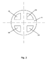
図2は、図1の膨張弁1用に好適なダイヤフラム6を示す。ダイヤフラム6は4つの貫通穴10を備えている。ダイヤフラム6が膨張弁1に取り付けられる際、それは貫通穴10が弁座4に対応する位置に配置されないようにして位置決めされる。それによって、ダイヤフラム6は弁座4に対して所要のシーリング効果を付与することができる。
FIG. 2 shows a
ダイヤフラム6が貫通穴10を備えているので、それは同じ厚さを有するが貫通穴10のないダイヤフラムよりも柔軟である。増大した柔軟性によりダイヤフラム6はサーモスタット要素の変化に応答してピストン8の動きに高速に反応することができる。それによって弁の応答時間は低減する。さらに、ダイヤフラム6のより正確な位置決めを得ることができ、それによって弁座4およびダイヤフラム6によって規定される弁の開度をより正確に調整することが可能である。
Since the
図3は、図1の膨張弁1用に好適な別のダイヤフラム6を示す。図3の下側においてダイヤフラム6は上方から見られ、図3の上側においてダイヤフラム6は断面図で示されている。
FIG. 3 shows another
図3のダイヤフラム6は、4つの隆起領域11を備えている。ダイヤフラム6が膨張弁1に取り付けられる際、それは隆起領域11が弁座4の位置に対応する位置に配置されるようにして、かつ隆起領域11がダイヤフラム6の他の部分よりも第1の弁部2の近くに配置されるようにして位置決めされる。それによって、ダイヤフラム6が弁の最小開度を規定する位置にある時にほぼ液密な接触がダイヤフラム6と弁座4との間にもたらされるのを保証することができる。
The
図4は、図1の膨張弁1用に適格なさらに別のダイヤフラム6を示す。図4のダイヤフラム6は、図4のダイヤフラム6もまた隆起領域11を備えていることから、図3のダイヤフラム6と極めて類似である。しかし、図4の隆起領域11は若干異なる様態で造形されている。
FIG. 4 shows yet another
1…膨張弁、2、3…弁部、4…弁座、5…出口開口、6…ダイヤフラム、7…圧縮ばね、8…ピストン、10…貫通穴、11…隆起領域。
DESCRIPTION OF SYMBOLS 1 ...
Claims (9)
液体状態の流体媒体を受けるよう構成された入口開口を備え、
少なくとも2つの出口開口(5)を備え、各々は少なくとも部分的に気体状態の流体媒体を供給するよう構成されており、
第1の弁部(2)と第2の弁部(3)を備え、
ダイヤフラム(6)を備え、
少なくとも2つの弁座(4)を備え、
各弁座(4)は出口開口(5)の1つと流体接続されており、各々の弁座(4)にダイヤフラム(6)が覆うように組合せられて膨張弁(1)の弁を形成しており、それによってダイヤフラム(6)の位置が同時に弁の各々の開度を規定し、
前記ダイアフラム(6)は、前記第1の弁部(2)に隣接して配置され、そして、第1の弁部(2)と第2の弁部(3)との間に位置し、前記第1の弁部は(2)は前記少なくとも2つの弁座(4)を有し、
前記ダイアフラム(6)は、ダイアフラム(6)の位置に向かって移動するピストン(8)によって、弁座(4)から離れる方向に移動し、そして
前記ダイアフラム(6)は、バネと、ダイアフラム(6)の位置に向かう方向とは反対の方向に移動するピストン(8)によって、弁座(4)に向かう方向に移動することを特徴とする、膨張弁(1)。 An expansion valve (1),
An inlet opening configured to receive a fluid medium in a liquid state;
Comprising at least two outlet openings (5), each configured to supply at least partially a gaseous fluid medium;
Comprising a first valve part (2) and a second valve part (3),
It has a diaphragm (6),
Comprising at least two valve seats (4),
Each valve seat (4) is fluidly connected to one of the outlet openings (5) and is combined with each valve seat (4) to cover the diaphragm (6) to form the valve of the expansion valve (1). So that the position of the diaphragm (6) simultaneously defines the opening of each of the valves ,
The diaphragm (6) is disposed adjacent to the first valve part (2) and is located between the first valve part (2) and the second valve part (3), first valve part (2) is closed at least two valve seats (4),
The diaphragm (6) is moved away from the valve seat (4) by a piston (8) moving towards the position of the diaphragm (6), and
The diaphragm (6) is moved in a direction toward the valve seat (4) by a spring and a piston (8) moving in a direction opposite to the direction toward the position of the diaphragm (6) . Expansion valve (1).
少なくとも1の圧縮器と、
少なくとも1の凝縮器と、
冷凍システムの冷媒流路に沿って並列して配置された少なくとも2つの蒸発器と、
請求項1〜8のいずれかに記載の膨張弁(1)とを備えており、前記膨張弁(1)は少なくとも2つの出口開口(5)の各々が蒸発器の1つに冷媒を供給するべく配置されるようにして配置されている、冷凍システム。 A refrigeration system,
At least one compressor;
At least one condenser;
At least two evaporators arranged in parallel along the refrigerant flow path of the refrigeration system;
9. An expansion valve (1) according to any one of the preceding claims, wherein the expansion valve (1) has at least two outlet openings (5) each supplying refrigerant to one of the evaporators. A refrigeration system that is arranged in such a way as to be arranged accordingly.
Applications Claiming Priority (3)
| Application Number | Priority Date | Filing Date | Title |
|---|---|---|---|
| DKPA200801630 | 2008-11-20 | ||
| DKPA200801630 | 2008-11-20 | ||
| PCT/DK2009/000242 WO2010057496A2 (en) | 2008-11-20 | 2009-11-19 | An expansion valve comprising a diaphragm and at least two outlet openings |
Publications (2)
| Publication Number | Publication Date |
|---|---|
| JP2012509455A JP2012509455A (en) | 2012-04-19 |
| JP5543481B2 true JP5543481B2 (en) | 2014-07-09 |
Family
ID=42198567
Family Applications (1)
| Application Number | Title | Priority Date | Filing Date |
|---|---|---|---|
| JP2011536740A Expired - Fee Related JP5543481B2 (en) | 2008-11-20 | 2009-11-19 | Expansion valve with diaphragm and at least two outlet openings |
Country Status (8)
| Country | Link |
|---|---|
| US (1) | US20110308274A1 (en) |
| EP (1) | EP2359080A2 (en) |
| JP (1) | JP5543481B2 (en) |
| CN (1) | CN102292609A (en) |
| BR (1) | BRPI0921071A2 (en) |
| MX (1) | MX2011005254A (en) |
| RU (1) | RU2481521C2 (en) |
| WO (1) | WO2010057496A2 (en) |
Families Citing this family (4)
| Publication number | Priority date | Publication date | Assignee | Title |
|---|---|---|---|---|
| CN109556327B (en) * | 2017-09-26 | 2022-01-04 | 开利公司 | Throttling distribution assembly and refrigerating system |
| CN110878996B (en) * | 2018-09-06 | 2021-09-28 | 天津华信机械有限公司 | Multifunctional expansion valve and air conditioning system |
| JP6945515B2 (en) * | 2018-11-06 | 2021-10-06 | 株式会社鷺宮製作所 | Temperature type expansion valve unit and refrigeration cycle system equipped with it |
| CN110776967B (en) * | 2019-11-13 | 2021-03-02 | 新奥(舟山)液化天然气有限公司 | Liquid natural gas separation and recovery device |
Family Cites Families (15)
| Publication number | Priority date | Publication date | Assignee | Title |
|---|---|---|---|---|
| US2491905A (en) * | 1944-05-29 | 1949-12-20 | Gen Controls Co | Refrigerating system |
| US3264837A (en) * | 1965-04-09 | 1966-08-09 | Westinghouse Electric Corp | Refrigeration system with accumulator means |
| GB1337112A (en) * | 1970-05-28 | 1973-11-14 | Rubery Owen & Co Ltd | Vehicle hydraulic transmission systems |
| US3772896A (en) * | 1972-03-02 | 1973-11-20 | Fluidics Inc | Heat exchange unit to regulate the temperature of recirculating hydraulic fluid for operating hydraulic systems of machinery |
| SU661183A1 (en) * | 1977-02-24 | 1979-05-05 | Институт Химии Ан Таджикской Сср | Thermal water regulator |
| JPS55133177U (en) * | 1979-03-13 | 1980-09-20 | ||
| JP3024854B2 (en) * | 1992-03-06 | 2000-03-27 | 太陽鉄工株式会社 | Valve driving method and valve |
| US6622983B2 (en) * | 2000-08-25 | 2003-09-23 | Lawrence Hall | Particle control valve |
| JP3995513B2 (en) * | 2001-06-19 | 2007-10-24 | 株式会社デンソー | Expansion valve with pressure detection function |
| US6626000B1 (en) * | 2002-10-30 | 2003-09-30 | Visteon Global Technologies, Inc. | Method and system for electronically controlled high side pressure regulation in a vapor compression cycle |
| JP2004270975A (en) * | 2003-03-06 | 2004-09-30 | Tgk Co Ltd | Flow rate control valve |
| JP4484656B2 (en) * | 2004-10-01 | 2010-06-16 | 株式会社鷺宮製作所 | Temperature-sensitive control valve and refrigeration cycle device |
| JP4783374B2 (en) * | 2004-10-21 | 2011-09-28 | ダンフォス・アクチ−セルスカブ | Valves used in cooling systems |
| WO2006101570A1 (en) * | 2005-03-18 | 2006-09-28 | Carrier Commercial Refrigeration, Inc. | Transcritical refrigeration with pressure addition relief valve |
| CZ296793B6 (en) * | 2005-06-03 | 2006-06-14 | Regulus Spol. S R. O. | Safety device arrangement of water heating system |
-
2009
- 2009-11-19 MX MX2011005254A patent/MX2011005254A/en active IP Right Grant
- 2009-11-19 BR BRPI0921071A patent/BRPI0921071A2/en not_active IP Right Cessation
- 2009-11-19 WO PCT/DK2009/000242 patent/WO2010057496A2/en active Application Filing
- 2009-11-19 JP JP2011536740A patent/JP5543481B2/en not_active Expired - Fee Related
- 2009-11-19 EP EP20090756244 patent/EP2359080A2/en not_active Withdrawn
- 2009-11-19 US US13/130,060 patent/US20110308274A1/en not_active Abandoned
- 2009-11-19 RU RU2011124352/06A patent/RU2481521C2/en not_active IP Right Cessation
- 2009-11-19 CN CN2009801549225A patent/CN102292609A/en active Pending
Also Published As
| Publication number | Publication date |
|---|---|
| CN102292609A (en) | 2011-12-21 |
| RU2011124352A (en) | 2012-12-27 |
| BRPI0921071A2 (en) | 2015-12-15 |
| JP2012509455A (en) | 2012-04-19 |
| WO2010057496A3 (en) | 2010-08-19 |
| US20110308274A1 (en) | 2011-12-22 |
| RU2481521C2 (en) | 2013-05-10 |
| MX2011005254A (en) | 2011-05-31 |
| EP2359080A2 (en) | 2011-08-24 |
| WO2010057496A2 (en) | 2010-05-27 |
Similar Documents
| Publication | Publication Date | Title |
|---|---|---|
| JP4283069B2 (en) | Compound valve | |
| US9714780B2 (en) | On-demand micro expansion valve for a refrigeration system | |
| JP5543481B2 (en) | Expansion valve with diaphragm and at least two outlet openings | |
| JP5620833B2 (en) | 3-way solenoid valve | |
| KR20110073215A (en) | Expansion valve | |
| KR20050054842A (en) | Expansion valve | |
| WO2006042544A1 (en) | Valve for use in a refrigeration system | |
| JP5570314B2 (en) | 3-way solenoid valve | |
| JP2012508364A (en) | Expansion valve with biasing means | |
| JP2006308257A (en) | Evaporator, refrigerant mixer, and heat pump using them | |
| TW200928259A (en) | Refrigerant floating expansion apparatus | |
| KR20040031244A (en) | Extension Valve Assembly for Air Conditioner of Vehicle | |
| JP2004003793A (en) | Throttle valve device and air conditioner | |
| JP2012220140A (en) | Expansion valve | |
| US11739956B2 (en) | Air conditioning apparatus | |
| JP5305860B2 (en) | Expansion valve mechanism and air conditioner equipped with the same | |
| KR20110085457A (en) | Thermal expansion valve of air conditioner for vehicle | |
| WO2009146704A1 (en) | An expansion valve comprising a valve part with a piston portion | |
| KR100930963B1 (en) | Expansion valve for air conditioner using stacked piezoelectric pilot valve | |
| JPH04258585A (en) | Electromagnetic valve | |
| JP2008070032A (en) | Expansion valve | |
| JPS6191468A (en) | Expansion valve for two-path evaporator | |
| KR20030009617A (en) | Expansion valve of airconditioner system for automobile | |
| JP2010139220A (en) | Expansion valve mechanism, and air conditioner installed with the same |
Legal Events
| Date | Code | Title | Description |
|---|---|---|---|
| A131 | Notification of reasons for refusal |
Free format text: JAPANESE INTERMEDIATE CODE: A131 Effective date: 20120925 |
|
| A521 | Written amendment |
Free format text: JAPANESE INTERMEDIATE CODE: A523 Effective date: 20121220 |
|
| A131 | Notification of reasons for refusal |
Free format text: JAPANESE INTERMEDIATE CODE: A131 Effective date: 20130709 |
|
| A521 | Written amendment |
Free format text: JAPANESE INTERMEDIATE CODE: A523 Effective date: 20131008 |
|
| TRDD | Decision of grant or rejection written | ||
| A01 | Written decision to grant a patent or to grant a registration (utility model) |
Free format text: JAPANESE INTERMEDIATE CODE: A01 Effective date: 20140408 |
|
| A61 | First payment of annual fees (during grant procedure) |
Free format text: JAPANESE INTERMEDIATE CODE: A61 Effective date: 20140508 |
|
| R150 | Certificate of patent or registration of utility model |
Ref document number: 5543481 Country of ref document: JP Free format text: JAPANESE INTERMEDIATE CODE: R150 |
|
| LAPS | Cancellation because of no payment of annual fees |