JP5543379B2 - Wind turbine with bearing seal - Google Patents
Wind turbine with bearing seal Download PDFInfo
- Publication number
- JP5543379B2 JP5543379B2 JP2010548120A JP2010548120A JP5543379B2 JP 5543379 B2 JP5543379 B2 JP 5543379B2 JP 2010548120 A JP2010548120 A JP 2010548120A JP 2010548120 A JP2010548120 A JP 2010548120A JP 5543379 B2 JP5543379 B2 JP 5543379B2
- Authority
- JP
- Japan
- Prior art keywords
- ring
- bearing
- wind turbine
- sealing ring
- sealing
- Prior art date
- Legal status (The legal status is an assumption and is not a legal conclusion. Google has not performed a legal analysis and makes no representation as to the accuracy of the status listed.)
- Expired - Fee Related
Links
Images


Classifications
-
- F—MECHANICAL ENGINEERING; LIGHTING; HEATING; WEAPONS; BLASTING
- F03—MACHINES OR ENGINES FOR LIQUIDS; WIND, SPRING, OR WEIGHT MOTORS; PRODUCING MECHANICAL POWER OR A REACTIVE PROPULSIVE THRUST, NOT OTHERWISE PROVIDED FOR
- F03D—WIND MOTORS
- F03D80/00—Details, components or accessories not provided for in groups F03D1/00 - F03D17/00
- F03D80/70—Bearing or lubricating arrangements
-
- F—MECHANICAL ENGINEERING; LIGHTING; HEATING; WEAPONS; BLASTING
- F16—ENGINEERING ELEMENTS AND UNITS; GENERAL MEASURES FOR PRODUCING AND MAINTAINING EFFECTIVE FUNCTIONING OF MACHINES OR INSTALLATIONS; THERMAL INSULATION IN GENERAL
- F16C—SHAFTS; FLEXIBLE SHAFTS; ELEMENTS OR CRANKSHAFT MECHANISMS; ROTARY BODIES OTHER THAN GEARING ELEMENTS; BEARINGS
- F16C19/00—Bearings with rolling contact, for exclusively rotary movement
- F16C19/02—Bearings with rolling contact, for exclusively rotary movement with bearing balls essentially of the same size in one or more circular rows
- F16C19/14—Bearings with rolling contact, for exclusively rotary movement with bearing balls essentially of the same size in one or more circular rows for both radial and axial load
- F16C19/18—Bearings with rolling contact, for exclusively rotary movement with bearing balls essentially of the same size in one or more circular rows for both radial and axial load with two or more rows of balls
- F16C19/181—Bearings with rolling contact, for exclusively rotary movement with bearing balls essentially of the same size in one or more circular rows for both radial and axial load with two or more rows of balls with angular contact
- F16C19/183—Bearings with rolling contact, for exclusively rotary movement with bearing balls essentially of the same size in one or more circular rows for both radial and axial load with two or more rows of balls with angular contact with two rows at opposite angles
- F16C19/184—Bearings with rolling contact, for exclusively rotary movement with bearing balls essentially of the same size in one or more circular rows for both radial and axial load with two or more rows of balls with angular contact with two rows at opposite angles in O-arrangement
-
- F—MECHANICAL ENGINEERING; LIGHTING; HEATING; WEAPONS; BLASTING
- F16—ENGINEERING ELEMENTS AND UNITS; GENERAL MEASURES FOR PRODUCING AND MAINTAINING EFFECTIVE FUNCTIONING OF MACHINES OR INSTALLATIONS; THERMAL INSULATION IN GENERAL
- F16C—SHAFTS; FLEXIBLE SHAFTS; ELEMENTS OR CRANKSHAFT MECHANISMS; ROTARY BODIES OTHER THAN GEARING ELEMENTS; BEARINGS
- F16C33/00—Parts of bearings; Special methods for making bearings or parts thereof
- F16C33/72—Sealings
- F16C33/76—Sealings of ball or roller bearings
-
- F—MECHANICAL ENGINEERING; LIGHTING; HEATING; WEAPONS; BLASTING
- F05—INDEXING SCHEMES RELATING TO ENGINES OR PUMPS IN VARIOUS SUBCLASSES OF CLASSES F01-F04
- F05B—INDEXING SCHEME RELATING TO WIND, SPRING, WEIGHT, INERTIA OR LIKE MOTORS, TO MACHINES OR ENGINES FOR LIQUIDS COVERED BY SUBCLASSES F03B, F03D AND F03G
- F05B2220/00—Application
- F05B2220/70—Application in combination with
- F05B2220/706—Application in combination with an electrical generator
- F05B2220/7066—Application in combination with an electrical generator via a direct connection, i.e. a gearless transmission
-
- F—MECHANICAL ENGINEERING; LIGHTING; HEATING; WEAPONS; BLASTING
- F05—INDEXING SCHEMES RELATING TO ENGINES OR PUMPS IN VARIOUS SUBCLASSES OF CLASSES F01-F04
- F05B—INDEXING SCHEME RELATING TO WIND, SPRING, WEIGHT, INERTIA OR LIKE MOTORS, TO MACHINES OR ENGINES FOR LIQUIDS COVERED BY SUBCLASSES F03B, F03D AND F03G
- F05B2240/00—Components
- F05B2240/50—Bearings
-
- F—MECHANICAL ENGINEERING; LIGHTING; HEATING; WEAPONS; BLASTING
- F05—INDEXING SCHEMES RELATING TO ENGINES OR PUMPS IN VARIOUS SUBCLASSES OF CLASSES F01-F04
- F05B—INDEXING SCHEME RELATING TO WIND, SPRING, WEIGHT, INERTIA OR LIKE MOTORS, TO MACHINES OR ENGINES FOR LIQUIDS COVERED BY SUBCLASSES F03B, F03D AND F03G
- F05B2240/00—Components
- F05B2240/57—Seals
-
- F—MECHANICAL ENGINEERING; LIGHTING; HEATING; WEAPONS; BLASTING
- F16—ENGINEERING ELEMENTS AND UNITS; GENERAL MEASURES FOR PRODUCING AND MAINTAINING EFFECTIVE FUNCTIONING OF MACHINES OR INSTALLATIONS; THERMAL INSULATION IN GENERAL
- F16C—SHAFTS; FLEXIBLE SHAFTS; ELEMENTS OR CRANKSHAFT MECHANISMS; ROTARY BODIES OTHER THAN GEARING ELEMENTS; BEARINGS
- F16C2300/00—Application independent of particular apparatuses
- F16C2300/10—Application independent of particular apparatuses related to size
- F16C2300/14—Large applications, e.g. bearings having an inner diameter exceeding 500 mm
-
- F—MECHANICAL ENGINEERING; LIGHTING; HEATING; WEAPONS; BLASTING
- F16—ENGINEERING ELEMENTS AND UNITS; GENERAL MEASURES FOR PRODUCING AND MAINTAINING EFFECTIVE FUNCTIONING OF MACHINES OR INSTALLATIONS; THERMAL INSULATION IN GENERAL
- F16C—SHAFTS; FLEXIBLE SHAFTS; ELEMENTS OR CRANKSHAFT MECHANISMS; ROTARY BODIES OTHER THAN GEARING ELEMENTS; BEARINGS
- F16C2360/00—Engines or pumps
- F16C2360/31—Wind motors
-
- Y—GENERAL TAGGING OF NEW TECHNOLOGICAL DEVELOPMENTS; GENERAL TAGGING OF CROSS-SECTIONAL TECHNOLOGIES SPANNING OVER SEVERAL SECTIONS OF THE IPC; TECHNICAL SUBJECTS COVERED BY FORMER USPC CROSS-REFERENCE ART COLLECTIONS [XRACs] AND DIGESTS
- Y02—TECHNOLOGIES OR APPLICATIONS FOR MITIGATION OR ADAPTATION AGAINST CLIMATE CHANGE
- Y02E—REDUCTION OF GREENHOUSE GAS [GHG] EMISSIONS, RELATED TO ENERGY GENERATION, TRANSMISSION OR DISTRIBUTION
- Y02E10/00—Energy generation through renewable energy sources
- Y02E10/70—Wind energy
- Y02E10/72—Wind turbines with rotation axis in wind direction
Landscapes
- Engineering & Computer Science (AREA)
- General Engineering & Computer Science (AREA)
- Mechanical Engineering (AREA)
- Life Sciences & Earth Sciences (AREA)
- Sustainable Development (AREA)
- Sustainable Energy (AREA)
- Chemical & Material Sciences (AREA)
- Combustion & Propulsion (AREA)
- Rolling Contact Bearings (AREA)
- Sealing Of Bearings (AREA)
- Wind Motors (AREA)
Abstract
Description
本発明は、軸受封止部(軸受シール)を備えた風力タービンに関し、特に、直接駆動型発電機を有する風力タービン、例えば1MW以上の直接駆動型風力タービンに関する。 The present invention relates to a wind turbine having a bearing sealing portion (bearing seal), and more particularly to a wind turbine having a direct drive generator, for example, a direct drive wind turbine of 1 MW or more.
直接駆動型発電機を備える風力タービンにおいては、発電機の回転子はローター(回転翼)によって直接に駆動される。メイン軸受は、ハウジングリングとローターとの間に配置され、ローターにかかる重力的および空力的負荷を吸収するように設計されている。特に、伝達機構のない直接駆動型システムにおいては、直径は大きくかつ円周速度は速い。メイン軸受の取替えが高コストになる場合には、メイン軸受のサービス寿命が風力タービンのサービス寿命をかなり決める。風力タービンが、近付き難い位置に、例えば海上に据え付けられているという環境では、サービス寿命期間中のメイン軸受の取替えは避けねばならない。メイン軸受のサービス寿命は、メイン軸受の回転部分と静止部分との間のオイル封止部のサービス寿命に大きく依存する。これらのオイル封止部は、オイルがメイン軸受内に留まるような十分な潤滑手段を保障することが要求される。オイル封止部の組立および分解は装置の解体を必要とする。 In a wind turbine provided with a direct drive generator, the rotor of the generator is directly driven by a rotor (rotary blade). The main bearing is located between the housing ring and the rotor and is designed to absorb gravitational and aerodynamic loads on the rotor. In particular, in a direct drive system without a transmission mechanism, the diameter is large and the circumferential speed is fast. If the replacement of the main bearing is costly, the service life of the main bearing will significantly determine the service life of the wind turbine. In an environment where the wind turbine is installed in an inaccessible location, eg at sea, replacement of the main bearing during the service life must be avoided. The service life of the main bearing largely depends on the service life of the oil seal between the rotating part and the stationary part of the main bearing. These oil seals are required to ensure sufficient lubrication means so that the oil remains in the main bearing. Assembly and disassembly of the oil seal requires disassembly of the device.
軸受封止部を有する風力タービンは、例えば国際公開第WO2004/015288号に開示されている。この軸受封止部は、軸受内輪と軸受外輪との間の間隙のどちらの側にも存在する単一の2要素封止部を備える。この封止部品の複雑な迷宮構造は、封止部の寿命時間を大幅に減少させうる。 A wind turbine having a bearing seal is disclosed in, for example, International Publication No. WO 2004/015288. This bearing seal comprises a single two-element seal that exists on either side of the gap between the bearing inner ring and the bearing outer ring. This complicated labyrinth structure of the sealing component can significantly reduce the lifetime of the sealing portion.
本発明は、オイル封止部を取替えるために風力タービンを解体する必要があるのを避けることを目的とする。 The present invention aims to avoid the need to dismantle the wind turbine to replace the oil seal.
本発明の目的は、回転翼(ローターブレード)を持つハブを支持する軸受を備えた風力タービンであって、該軸受は該ハブに結合された回転軸受輪および静止軸受輪、該軸受輪の間の潤滑領域を備え、該潤滑領域は該回転軸受輪と静止部分との間の間隙を封止する第1封止リングによって両端で制限されて潤滑バリヤを形成する風力タービンにおいて、該潤滑領域の1端または両端において、追加の封止リングが、封止されるべき該間隙内若しくは近傍において該第1封止リングから離れて配置されていることを特徴とする、上記風力タービンによって達せられる。 An object of the present invention is a wind turbine provided with a bearing that supports a hub having rotor blades (rotor blades), the bearing being connected between the rotating bearing ring and stationary bearing ring coupled to the hub, and the bearing ring. In a wind turbine that is constrained at both ends by a first sealing ring that seals a gap between the rotary bearing ring and a stationary portion to form a lubrication barrier. At one or both ends, an additional sealing ring is achieved by the wind turbine, characterized in that it is arranged away from the first sealing ring in or near the gap to be sealed.
この追加の封止リングは、風力タービンの回転軸の周りにおよびローターブレードとハウジングとの間の部品の周りに予め存在するので、第1封止リングが追加の封止リングで取替えられる必要がある場合に、ローターは解体される必要がない。 Since this additional sealing ring is pre-existing around the axis of rotation of the wind turbine and around the part between the rotor blade and the housing, the first sealing ring needs to be replaced by an additional sealing ring. In some cases, the rotor need not be dismantled.
追加の封止リングは、第1封止リングと取替えるために使用されうる。代替的に、追加の封止リングは第1封止リングを支援するために使用されうる。この目的のために、第1封止リングと追加の封止リングとは最初から組合せて使用されうる。 An additional sealing ring can be used to replace the first sealing ring. Alternatively, an additional sealing ring can be used to assist the first sealing ring. For this purpose, the first sealing ring and the additional sealing ring can be used in combination from the start.
好ましくは、回転軸受輪と静止部分との間の間隙の両端は、第1封止リングおよび追加の封止リングを備える。 Preferably, both ends of the gap between the rotary bearing ring and the stationary part are provided with a first sealing ring and an additional sealing ring.
使用中は、潤滑媒体、例えば潤滑オイルの薄い膜が、作動中の封止リングをこの封止リングによって係合せられた封止面から分離する。 In use, a thin film of lubricating medium, such as lubricating oil, separates the active sealing ring from the sealing surface engaged by the sealing ring.
任意的に、第3の封止リングまたはそれ以上の封止リングが、支援封止部として及び/又は置換え封止部として使用されうる。 Optionally, a third sealing ring or higher sealing ring can be used as an assistive seal and / or as a replacement seal.
別の実施態様においては、静止軸受輪は非係合区間を備えない。これは、もし追加の封止リングが両軸受輪の間隔を空ける支持輪に搭載される場合、軸受内輪は、縮小された(または拡大された)直径を有する溝(または部分)を備えておらず、追加の封止リングと係合しないことを意味する。言い換えると、軸受内輪は、支持輪を第2の封止位置へ移動させた後に追加の封止リングと協働するだけの第2の封止領域を備えていない。 In another embodiment, the stationary bearing ring does not comprise a non-engaging section. This is because if the additional sealing ring is mounted on a support ring that is spaced between the bearing rings, the bearing inner ring is provided with a groove (or portion) having a reduced (or enlarged) diameter. Meaning that it does not engage the additional sealing ring. In other words, the bearing inner ring does not include a second sealing area that only cooperates with the additional sealing ring after moving the support ring to the second sealing position.
潤滑領域は、軸受内輪および外輪の間隔を空ける軸受玉を含みうる。 The lubrication region may include bearing balls that space the bearing inner and outer rings.
典型的には軸受内輪は静止しており、一方軸受外輪は、歯車装置のないローターによって直接駆動されて回転する。 Typically, the bearing inner ring is stationary, while the bearing outer ring is driven directly by a rotor without gearing and rotates.
オイル封止部のサービス寿命を可能な限り延ばすために、封止面は鍛鋼で作られ、研磨された表面を持っていることが好ましい。これにより封止リングの磨耗は実質的に減少させられうる。 In order to extend the service life of the oil seal as much as possible, the sealing surface is preferably made of forged steel and has a polished surface. This can substantially reduce wear on the sealing ring.
封止部および外側封止部は、延長されたサービス寿命を得るために、例えば可撓性材料、例えばゴムから作られ、または好ましくはテフロン(登録商標)若しくは同様の材料を含有する。 The seal and the outer seal are made, for example, from a flexible material, such as rubber, or preferably contain Teflon or similar material to obtain an extended service life.
特別な実施態様においては、軸受内輪および外輪のそれぞれの側面部分と封止的に係合する2つの封止リングを保持するための2つの同心溝を備える支持部材が使用される。このようにして、支持部材のみが封止リングの一つを取り替えるために外される必要がある。 In a special embodiment, a support member is used that comprises two concentric grooves for holding two sealing rings that sealingly engage the respective side portions of the bearing inner and outer rings. In this way, only the support member needs to be removed to replace one of the sealing rings.
別の可能な実施態様においては、第1封止リングおよび追加の封止リングは、同心凹部を備えた支持部材に向き合う静止バリヤ輪内に搭載され、該支持部材は、第1の封止位置(ここでは追加の封止リングは該凹部に向き合い、一方、第1封止リングは支持輪と封止的に係合する)から、第2の位置(ここでは置換リングが支持輪と封止的に係合する)へ移動させられうる。このようにして、第1封止リングは、支持部材をその第2位置へ単に動かすことにより簡単で費用効果の高いやり方で、追加の封止リングによって置き換えられうる。 In another possible embodiment, the first sealing ring and the additional sealing ring are mounted in a stationary barrier ring facing a support member with a concentric recess, the support member being in a first sealing position. From here (the additional sealing ring faces the recess, while the first sealing ring sealingly engages the support wheel), the second position (here the replacement ring seals with the support wheel) To be engaged). In this way, the first sealing ring can be replaced by an additional sealing ring in a simple and cost-effective manner by simply moving the support member to its second position.
別の代替的な実施態様においては、輪部材は該2つの軸受輪の間隔を空けるのに使用されることができ、各軸受輪について封止リングは該輪部材で間隙を封止し、該輪部材は、該輪部材を静止軸受輪へ係止するのに適した第1固定手段および輪部材を回転軸受輪へ係止するのに適した第2固定手段を備えている。第1固定手段が輪部材を静止部材輪へ係止するとき、輪部材と回転軸受輪とを橋渡しする封止リングは動的な封止を形成する。磨耗による故障の後、第1固定手段は不活動にされ、第2固定手段は輪部材を回転軸受輪へ係止するのに使われうる。この状況において、輪部材は回転軸受輪と一緒に回転させられ、輪部材と静止軸受輪との間の封止は動的な封止になる。 In another alternative embodiment, a ring member can be used to space the two bearing rings, and for each bearing ring a sealing ring seals the gap with the ring member, The ring member includes first fixing means suitable for locking the ring member to the stationary bearing ring and second fixing means suitable for locking the ring member to the rotating bearing ring. When the first fixing means locks the ring member to the stationary member ring, the sealing ring that bridges the ring member and the rotating bearing ring forms a dynamic seal. After a failure due to wear, the first fixing means can be deactivated and the second fixing means can be used to lock the ring member to the rotating bearing ring. In this situation, the ring member is rotated together with the rotating bearing ring, and the seal between the ring member and the stationary bearing ring is a dynamic seal.
以下、本発明は、図面を参照しつつ本発明の様々な実施態様を記載することによって説明される。 The present invention will now be described by describing various embodiments of the invention with reference to the drawings.
図1は、タワー(1)上に設置されかつハウジング(2)を有する風力タービンを示す。このハウジング(2)は垂直軸の周りを回転しうる。ハウジングリング(4)は、一方の側でハウジング(2)に、そして他方の側でメイン軸受(9)に取り付けられている。ローター(R)は、ブレード(10)を持つハブ(11)を備え、メイン軸受(9)に取り付けられており、中心線(3)の周りを回転しうる。ハブ(11)は、前側をキャップ(12)で覆われている。永久磁石(5)を備える発電機ローター(6)は、発電機フランジ(8)を介してメイン軸受(9)に取り付けられ、ローター(R)と共に回転する。発電機ステーター(7)は、ハウジングリング(4)上に搭載される。永久磁石(5)は、発電機ステーター(7)の巻線に沿って動き、電力を発生する。ハウジング(2)は、ローター(R)が風の方向に向きうるように垂直軸の周りを回転できる。 FIG. 1 shows a wind turbine installed on a tower (1) and having a housing (2). This housing (2) can rotate about a vertical axis. The housing ring (4) is attached to the housing (2) on one side and to the main bearing (9) on the other side. The rotor (R) includes a hub (11) having a blade (10), is attached to a main bearing (9), and can rotate around a center line (3). The hub (11) is covered with a cap (12) on the front side. A generator rotor (6) having a permanent magnet (5) is attached to the main bearing (9) via a generator flange (8) and rotates together with the rotor (R). The generator stator (7) is mounted on the housing ring (4). The permanent magnet (5) moves along the windings of the generator stator (7) and generates electric power. The housing (2) can rotate about a vertical axis so that the rotor (R) can be oriented in the wind direction.
風力タービンは直接駆動型発電機を備える設計がなされ、上記発電機ローター(6)はローター(R)によって直接に駆動される。メイン軸受は、ハウジングリング(4)とローター(R)との間に置かれ、ローター(R)にかかる重力的および空力的負荷に耐えうるように設計される。 The wind turbine is designed with a direct drive generator, and the generator rotor (6) is directly driven by the rotor (R). The main bearing is placed between the housing ring (4) and the rotor (R) and is designed to withstand the gravitational and aerodynamic loads on the rotor (R).
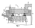
図2はメイン軸受(9)を示し、該メイン軸受(9)は玉(18)を具備する玉(10)軸受であり、オイル封止装置は玉(18)の両側で静止軸受内輪(17)と回転軸受外輪(16)との間に搭載される。軸受内輪(17)はハウジングリング(4)のフランジ(26)に搭載される。発電機フランジ(8)およびハブ(11)は軸受外輪(16)に搭載される。支持輪(14)はボルト(13)によって軸受外輪(16)に結合される。支持輪(14)の円筒形部分(27)は、軸受内輪(17)と軸受外輪(16)との間に位置される。静的封止部(19)は、円筒形部分(27)の外周に搭載され、軸受外輪(16)と支持輪(14)との間の開口部を封止する。支持輪(14)の内周上には内側封止部(20)および外側封止部(21)が搭載され、内側封止部(20)は玉(18)のような潤滑されるべき部分に最も近く、外側封止部(21)は周辺環境に最も近い。支持輪(14)の近くの軸受内輪(17)の外周は、外側封止面(28)および潤滑されるべき部分に最も近い内側封止面(29)を有している。 FIG. 2 shows a main bearing (9), the main bearing (9) is a ball (10) bearing comprising balls (18), and the oil sealing device is provided on both sides of the ball (18) with stationary bearing inner rings (17). ) And the rotary bearing outer ring (16). The bearing inner ring (17) is mounted on the flange (26) of the housing ring (4). The generator flange (8) and the hub (11) are mounted on the bearing outer ring (16). The support ring (14) is coupled to the bearing outer ring (16) by a bolt (13). The cylindrical portion (27) of the support ring (14) is located between the bearing inner ring (17) and the bearing outer ring (16). The static sealing part (19) is mounted on the outer periphery of the cylindrical part (27), and seals the opening between the bearing outer ring (16) and the support ring (14). An inner sealing portion (20) and an outer sealing portion (21) are mounted on the inner periphery of the support wheel (14), and the inner sealing portion (20) is a portion to be lubricated, such as a ball (18). The outer seal (21) is closest to the surrounding environment. The outer circumference of the bearing inner ring (17) near the support ring (14) has an outer sealing surface (28) and an inner sealing surface (29) closest to the part to be lubricated.
図2の実施態様においては、封止リングは支持輪(14)に搭載される。代替的に、封止リング(20、21)の1つまたは両方が、支持輪(14)の表面と封止的に係合するように静止軸受輪内に搭載されうる。 In the embodiment of FIG. 2, the sealing ring is mounted on the support wheel (14). Alternatively, one or both of the sealing rings (20, 21) can be mounted in the stationary bearing ring so as to sealingly engage the surface of the support ring (14).
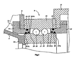
図3は本発明に係る風力タービンの別の実施態様を示し、該実施態様は図2の実施態様に大部分で類似している(同一部分には同一の符号が与えられる)。図3において、内側封止部(20A)は、封止リング(20A)を格納する深い凹部内で、磨耗を防ぐために軸受内輪(17)の向かい合う面から離れて、配置される。外側封止リング(21A)の故障後にのみ、追加の外側封止リング(20A)がその凹部から移動させられ、内側封止リング(20A)を置き換えるために使われる。別の代替的実施態様においては、追加の外側封止部(20A)を格納しておく凹部は、どこか他に、例えば軸受内輪(17)に面していない表面に配置されうる。代替的には、内側封止リング(21A)が、外側封止リング(20A)の故障後に使われるべき置換リングとして、深い凹部に格納されうる。 FIG. 3 shows another embodiment of a wind turbine according to the invention which is largely similar to the embodiment of FIG. 2 (the same parts are given the same reference numerals). In FIG. 3, the inner seal (20A) is placed in a deep recess that houses the seal ring (20A), away from the facing surface of the bearing inner ring (17) to prevent wear. Only after failure of the outer sealing ring (21A), the additional outer sealing ring (20A) is moved out of its recess and used to replace the inner sealing ring (20A). In another alternative embodiment, the recess for storing the additional outer seal (20A) may be located somewhere else, for example on the surface not facing the bearing inner ring (17). Alternatively, the inner sealing ring (21A) can be stored in a deep recess as a replacement ring to be used after failure of the outer sealing ring (20A).
図4は1つの実施態様を示し、この実施態様は、図2の実施態様のように、同時に活動的な2つの封止リング(20、21)と、軸受内輪(17)から離れた凹部に格納された予備で追加の2つの封止リング(20B、21B)とを有する。代替的な実施態様においては、1つ又は複数の追加の封止リングが、潤滑媒体と接触する潤滑領域内の凹部に格納されうる。 FIG. 4 shows an embodiment, which, like the embodiment of FIG. 2, has two active sealing rings (20, 21) and a recess away from the bearing inner ring (17) at the same time. It has two additional sealing rings (20B, 21B) with a stored spare. In an alternative embodiment, one or more additional sealing rings can be stored in a recess in the lubrication area that contacts the lubrication medium.
図5はある実施態様を概略的に示し、そこでは封止リング(20C)は、軸受内輪(17C)と軸受外輪(16C)との間の間隙を直接封止する。追加の置換用封止部(21C)は、軸受内輪(17C)の側面上の凹部に格納される。 FIG. 5 schematically illustrates an embodiment in which the sealing ring (20C) directly seals the gap between the bearing inner ring (17C) and the bearing outer ring (16C). The additional replacement sealing portion (21C) is stored in the recess on the side surface of the bearing inner ring (17C).
図6は、支持部材(14D)を有する1つの実施態様を示し、該支持部材(14D)は、軸受内輪および外輪(17D、16D)のそれぞれの側面部分と封止的に係合する2つの封止リング(19D、21D)を保持するための2つの同心溝を備えている。追加の封止リング(20D)は支持部材(14D)の別の凹部に格納される。代替的な実施態様においては、余分の一つまたは複数の封止リングが、潤滑媒体と接触する封止リング(19D、20D)間の潤滑領域内の1つの凹部に格納されうる。 FIG. 6 shows one embodiment having a support member (14D), the support member (14D) being in two sealing engagements with respective side portions of the bearing inner and outer rings (17D, 16D). Two concentric grooves for holding the sealing rings (19D, 21D) are provided. The additional sealing ring (20D) is stored in another recess of the support member (14D). In an alternative embodiment, the extra one or more sealing rings can be stored in one recess in the lubrication region between the sealing rings (19D, 20D) in contact with the lubricating medium.
図7においては、(発電機フランジ(8)とハブ(11)との間に)支持輪(14E)と軸受外輪(16)との間にスペーサ(15)がある。支持輪(14E)は、封止リング(21E)が支持部材(14E)に対して封止するところの第1の位置にある。追加の封止リング(20E)は、支持輪(14E)と追加の封止リング(20E)との間で接触がないよう、支持輪(14E)の向かい合う面内の溝(22)に向く。追加の封止リング(20E)は、現在作動中の封止部(21E)の背後にあるので、汚染または光から影響を受けず、かつ追加の封止リング(20E)に対する摩耗がない。このようにして、追加の封止部(20E)は使用の準備の状態にあり、そして第1の位置にある限り、環境の影響から保護される。ある期間の後、封止リング(21E)のサービス寿命の終りが、封止リング(21E)と封止面(28)との間からのオイル漏れの観測によって検出される。封止リング(21E)がサービス寿命の終りにあることを決定した後、スペーサー(15)が移動され、支持輪(14E)が内側に押され、軸受外輪(16)にボルト(13)によって固定される(発電機フランジ(8)またはハブ(11)を介して)。支持輪(14E)は、今やその第2の位置にある。この第2の位置において、封止リング(20E)は支持輪(14E)の内側面を封止する。 In FIG. 7, there is a spacer (15) between the support wheel (14E) and the bearing outer ring (16) (between the generator flange (8) and the hub (11)). The support ring (14E) is in the first position where the sealing ring (21E) seals against the support member (14E). The additional sealing ring (20E) faces the groove (22) in the opposite face of the support ring (14E) so that there is no contact between the support ring (14E) and the additional seal ring (20E). Since the additional sealing ring (20E) is behind the currently active seal (21E), it is not affected by contamination or light and there is no wear on the additional sealing ring (20E). In this way, the additional seal (20E) is ready for use and is protected from environmental influences as long as it is in the first position. After a period of time, the end of the service life of the sealing ring (21E) is detected by observing an oil leak between the sealing ring (21E) and the sealing surface (28). After determining that the sealing ring (21E) is at the end of the service life, the spacer (15) is moved, the support ring (14E) is pushed inward and secured to the bearing outer ring (16) with bolts (13) (Via generator flange (8) or hub (11)). The support wheel (14E) is now in its second position. In this second position, the sealing ring (20E) seals the inner surface of the support wheel (14E).
図8において、輪部材(14F)は該2つの軸受輪(16F、17F)を分離する。各軸受輪について、封止リング(20F、21F)は、輪部材(14F)との間隙を封止する。輪部材は、輪部材(14F)を静止軸受輪(17F)に対して固定する第1の固定部材(13F)および輪部材(14F)を回転軸受輪(16F)に対して固定する第2の固定部材(13G)備える。第1の固定部材(13F)が、輪部材(14F)を静止軸受輪(17F)に対して固定するとき、輪部材(14F)と回転軸受輪(16F)とをブリッジする封止リング(20F)が、動的な封止を形成する。摩耗に起因する故障の後、第1の固定手段(13F)は不活動的にされえ、第2の固定手段(13G)が輪部材を回転軸受輪(16F)へ固定するために使用されうる。この状況では、輪部材(14F)は回転軸受輪(16F)と一緒に回転せられ、輪部材(14F)と静止軸受輪(17F)との間の封止が動的な封止になる。 In FIG. 8, a ring member (14F) separates the two bearing rings (16F, 17F). For each bearing ring, the sealing rings (20F, 21F) seal the gap with the ring member (14F). The ring member includes a first fixing member (13F) for fixing the ring member (14F) to the stationary bearing ring (17F) and a second fixing unit for fixing the ring member (14F) to the rotating bearing ring (16F). A fixing member (13G) is provided. When the first fixing member (13F) fixes the ring member (14F) to the stationary bearing ring (17F), the sealing ring (20F) bridges the ring member (14F) and the rotary bearing ring (16F). ) Form a dynamic seal. After a failure due to wear, the first fixing means (13F) can be deactivated and the second fixing means (13G) can be used to fix the ring member to the rotating bearing ring (16F). . In this situation, the ring member (14F) is rotated together with the rotating bearing ring (16F), and the seal between the ring member (14F) and the stationary bearing ring (17F) is a dynamic seal.
図面に示した実施態様において、メイン軸受は2列玉軸受として示されている。本発明が、他の型の玉軸受およびローラー軸受またはそれ以外の任意の軸受に対して適用可能であることは、当業者にとって明らかである。
In the embodiment shown in the drawings, the main bearing is shown as a two-row ball bearing. It will be apparent to those skilled in the art that the present invention is applicable to other types of ball and roller bearings or any other bearing.
Claims (6)
Applications Claiming Priority (3)
| Application Number | Priority Date | Filing Date | Title |
|---|---|---|---|
| EP08102156A EP2096303A1 (en) | 2008-02-29 | 2008-02-29 | Windturbine comprising a bearing seal |
| EP08102156.0 | 2008-02-29 | ||
| PCT/EP2009/052363 WO2009106610A1 (en) | 2008-02-29 | 2009-02-27 | Windturbine comprising a bearing seal |
Publications (2)
| Publication Number | Publication Date |
|---|---|
| JP2011514473A JP2011514473A (en) | 2011-05-06 |
| JP5543379B2 true JP5543379B2 (en) | 2014-07-09 |
Family
ID=40259122
Family Applications (1)
| Application Number | Title | Priority Date | Filing Date |
|---|---|---|---|
| JP2010548120A Expired - Fee Related JP5543379B2 (en) | 2008-02-29 | 2009-02-27 | Wind turbine with bearing seal |
Country Status (9)
| Country | Link |
|---|---|
| US (1) | US8882459B2 (en) |
| EP (2) | EP2096303A1 (en) |
| JP (1) | JP5543379B2 (en) |
| KR (1) | KR101542355B1 (en) |
| CN (1) | CN102016302B (en) |
| AT (1) | ATE537359T1 (en) |
| BR (1) | BRPI0908901A2 (en) |
| CA (1) | CA2717041C (en) |
| WO (1) | WO2009106610A1 (en) |
Families Citing this family (11)
| Publication number | Priority date | Publication date | Assignee | Title |
|---|---|---|---|---|
| EP1927795A1 (en) | 2006-11-28 | 2008-06-04 | Darwind Development & Demonstration BV | Oil seal device |
| EP2096303A1 (en) | 2008-02-29 | 2009-09-02 | Darwind Holding B.V. | Windturbine comprising a bearing seal |
| NO20092984A1 (en) * | 2009-09-11 | 2011-02-14 | Blaaster Wind Tech As | Wind turbine |
| US8043012B2 (en) * | 2009-09-30 | 2011-10-25 | General Electric Company | Seal arrangement and a brush seal for a wind turbine |
| DE202011110128U1 (en) | 2011-04-05 | 2012-12-19 | Imo Holding Gmbh | Slewing connection for underwater operation |
| US9316119B2 (en) * | 2011-09-15 | 2016-04-19 | United Technologies Corporation | Turbomachine secondary seal assembly |
| TWI441981B (en) | 2011-11-25 | 2014-06-21 | Ind Tech Res Inst | Hub sealing apparatus for windmill |
| GB201412893D0 (en) * | 2014-07-21 | 2014-09-03 | A E S Engineering Ltd | Replaceable gland insert for increased life |
| EP3173642B1 (en) * | 2015-11-27 | 2018-07-18 | GE Renewable Technologies Wind B.V. | Wind turbine generator with bearing system and seal |
| EP3616843A1 (en) * | 2018-08-29 | 2020-03-04 | Siemens Gamesa Renewable Energy A/S | Tool for mounting a seal in a groove or gap on a wind-turbine |
| CN115261794B (en) * | 2022-07-29 | 2023-05-05 | 中国地质大学(北京) | Bearing applied to air rudder of ultra-high sound velocity aircraft and preparation method thereof |
Family Cites Families (22)
| Publication number | Priority date | Publication date | Assignee | Title |
|---|---|---|---|---|
| PL76196B1 (en) * | 1970-06-10 | 1975-02-28 | ||
| US4008897A (en) * | 1973-09-28 | 1977-02-22 | Howaldtswerke-Deutsche Werft Aktiengesellschaft Hamburg Und Kiel | Seals for rotating shafts, especially for stern tube seals for ships |
| JPH03107567U (en) * | 1990-02-22 | 1991-11-06 | ||
| JP2872583B2 (en) * | 1994-08-05 | 1999-03-17 | 新キャタピラー三菱株式会社 | Storage structure of seal ring |
| FR2742837B1 (en) | 1995-12-21 | 1998-02-20 | Eurocopter France | SEALING DEVICE FOR A ROTATING SHAFT |
| US5605337A (en) * | 1996-03-13 | 1997-02-25 | General Motors Corporation | Pivoting seal for oil-filled rotating machine |
| NL1013129C2 (en) * | 1999-09-24 | 2001-03-27 | Lagerwey Windturbine B V | Windmill. |
| CA2288230A1 (en) * | 1999-10-27 | 2001-04-27 | Thomas Wilson Ramsay | Multiple lip seal cartridge and adjustable sleeve |
| EP1710432B1 (en) | 2000-09-25 | 2014-04-30 | STX Heavy Industries Co., Ltd. | Wind power generator |
| US20040026867A1 (en) | 2002-08-09 | 2004-02-12 | Adams David J. | Bearing seal |
| EP1705392B2 (en) | 2003-11-18 | 2016-08-31 | NTN Corporation | Double-row self-aligning roller bearing and device for supporting wind turbine generator main shaft |
| US7075192B2 (en) | 2004-04-19 | 2006-07-11 | Northern Power Systems, Inc. | Direct drive wind turbine |
| DE102004052598A1 (en) * | 2004-10-29 | 2006-05-04 | Aktiebolaget Skf | Wind turbine |
| GB0500390D0 (en) * | 2005-01-10 | 2005-02-16 | Hansen Transmissions Int | Bearing assembly |
| US7591593B2 (en) * | 2005-02-04 | 2009-09-22 | Ntn Corporation | Sealed rolling bearing |
| EP1856409B1 (en) * | 2005-03-09 | 2014-11-12 | The Timken Company | Wind turbine bearing system |
| WO2006105529A1 (en) * | 2005-03-30 | 2006-10-05 | Inspire Pharmaceuticals, Inc. | Process for the preparation of 4,6-disubstituted-tetrahydro-furo, thieno, pyrrolo and cyclopenta-[3,4][1,3]dioxoles |
| US7401664B2 (en) | 2006-04-28 | 2008-07-22 | Varco I/P | Top drive systems |
| EP1927795A1 (en) * | 2006-11-28 | 2008-06-04 | Darwind Development & Demonstration BV | Oil seal device |
| CN200994092Y (en) * | 2006-12-22 | 2007-12-19 | 无锡市明通动力附件厂 | Explosion-proof outer rotor axial-flow fan motor structure |
| CN200986016Y (en) * | 2006-12-22 | 2007-12-05 | 郑州机械研究所 | Pressure lubricating circuit system suitable for epicyclic gear transmission |
| EP2096303A1 (en) | 2008-02-29 | 2009-09-02 | Darwind Holding B.V. | Windturbine comprising a bearing seal |
-
2008
- 2008-02-29 EP EP08102156A patent/EP2096303A1/en not_active Withdrawn
-
2009
- 2009-02-27 JP JP2010548120A patent/JP5543379B2/en not_active Expired - Fee Related
- 2009-02-27 EP EP09714228A patent/EP2260207B1/en active Active
- 2009-02-27 AT AT09714228T patent/ATE537359T1/en active
- 2009-02-27 CA CA2717041A patent/CA2717041C/en not_active Expired - Fee Related
- 2009-02-27 BR BRPI0908901A patent/BRPI0908901A2/en not_active IP Right Cessation
- 2009-02-27 US US12/919,913 patent/US8882459B2/en active Active
- 2009-02-27 KR KR1020107021241A patent/KR101542355B1/en not_active IP Right Cessation
- 2009-02-27 CN CN2009801139470A patent/CN102016302B/en active Active
- 2009-02-27 WO PCT/EP2009/052363 patent/WO2009106610A1/en active Application Filing
Also Published As
| Publication number | Publication date |
|---|---|
| JP2011514473A (en) | 2011-05-06 |
| CA2717041A1 (en) | 2009-09-03 |
| BRPI0908901A2 (en) | 2015-09-15 |
| EP2260207B1 (en) | 2011-12-14 |
| WO2009106610A1 (en) | 2009-09-03 |
| CN102016302B (en) | 2013-04-03 |
| US20110200427A1 (en) | 2011-08-18 |
| KR101542355B1 (en) | 2015-08-06 |
| KR20100138957A (en) | 2010-12-31 |
| EP2260207A1 (en) | 2010-12-15 |
| CN102016302A (en) | 2011-04-13 |
| ATE537359T1 (en) | 2011-12-15 |
| EP2096303A1 (en) | 2009-09-02 |
| US8882459B2 (en) | 2014-11-11 |
| CA2717041C (en) | 2017-03-14 |
Similar Documents
| Publication | Publication Date | Title |
|---|---|---|
| JP5543379B2 (en) | Wind turbine with bearing seal | |
| US7988364B2 (en) | Lubrication seal and wind turbine with lubrication seal | |
| WO2010007677A1 (en) | Bearing structure and wind power generator | |
| JP6419177B2 (en) | Propeller blade support device | |
| EP2871377B1 (en) | Bearing unit for fluid machinery application | |
| JP6832335B2 (en) | Drive device | |
| US8061901B2 (en) | Extension member for a flinger of a bearing | |
| ES2906786T3 (en) | Composite main bearing arrangement for a wind turbine | |
| JP2006506577A (en) | Wind turbine gear unit with integrated rotor bearing | |
| US20160118855A1 (en) | Motor, Positioning Device, Conveyance Device | |
| JP2004248492A (en) | Seal construction for motor, motor, and motor for automatic transmission of automobile | |
| JP2007247711A (en) | Rolling bearing for underwater rotary device | |
| JP2007276022A (en) | Rotary shaft support device | |
| JP2011208662A (en) | Rolling bearing | |
| JP2007187234A (en) | Oil seal | |
| US9765791B2 (en) | Turbo compressor | |
| JP2009052681A (en) | Bearing structure | |
| JP2008190655A (en) | Sealing device | |
| JP2008261357A (en) | Rotating shaft supporting structure of wind generator | |
| JP2008095794A (en) | Creep preventing rolling bearing and rolling bearing device | |
| KR101150520B1 (en) | Bearing assembly | |
| JP2005265124A (en) | Rolling bearing with balancer | |
| JPH0690544A (en) | Sealing device for rotary shaft of motor | |
| JP2014169626A (en) | Rotation supporting device for water pump |
Legal Events
| Date | Code | Title | Description |
|---|---|---|---|
| A621 | Written request for application examination |
Free format text: JAPANESE INTERMEDIATE CODE: A621 Effective date: 20120227 |
|
| A977 | Report on retrieval |
Free format text: JAPANESE INTERMEDIATE CODE: A971007 Effective date: 20130621 |
|
| A131 | Notification of reasons for refusal |
Free format text: JAPANESE INTERMEDIATE CODE: A131 Effective date: 20130710 |
|
| A521 | Request for written amendment filed |
Free format text: JAPANESE INTERMEDIATE CODE: A523 Effective date: 20131010 |
|
| TRDD | Decision of grant or rejection written | ||
| A01 | Written decision to grant a patent or to grant a registration (utility model) |
Free format text: JAPANESE INTERMEDIATE CODE: A01 Effective date: 20140422 |
|
| A61 | First payment of annual fees (during grant procedure) |
Free format text: JAPANESE INTERMEDIATE CODE: A61 Effective date: 20140508 |
|
| R150 | Certificate of patent or registration of utility model |
Ref document number: 5543379 Country of ref document: JP Free format text: JAPANESE INTERMEDIATE CODE: R150 |
|
| R250 | Receipt of annual fees |
Free format text: JAPANESE INTERMEDIATE CODE: R250 |
|
| LAPS | Cancellation because of no payment of annual fees |