JP5535155B2 - Flow path switching valve and fluid material discharge control device using the same - Google Patents
Flow path switching valve and fluid material discharge control device using the same Download PDFInfo
- Publication number
- JP5535155B2 JP5535155B2 JP2011192486A JP2011192486A JP5535155B2 JP 5535155 B2 JP5535155 B2 JP 5535155B2 JP 2011192486 A JP2011192486 A JP 2011192486A JP 2011192486 A JP2011192486 A JP 2011192486A JP 5535155 B2 JP5535155 B2 JP 5535155B2
- Authority
- JP
- Japan
- Prior art keywords
- discharge
- seat surface
- valve seat
- flow path
- chamber
- Prior art date
- Legal status (The legal status is an assumption and is not a legal conclusion. Google has not performed a legal analysis and makes no representation as to the accuracy of the status listed.)
- Active
Links
- 239000000463 material Substances 0.000 title claims description 55
- 239000012530 fluid Substances 0.000 title claims description 24
- 238000002347 injection Methods 0.000 claims description 36
- 239000007924 injection Substances 0.000 claims description 36
- 230000009969 flowable effect Effects 0.000 claims description 27
- 238000005192 partition Methods 0.000 claims description 24
- 238000007599 discharging Methods 0.000 claims description 6
- 230000005489 elastic deformation Effects 0.000 claims description 5
- 230000007704 transition Effects 0.000 claims 1
- 239000004519 grease Substances 0.000 description 45
- 238000004891 communication Methods 0.000 description 14
- 230000006835 compression Effects 0.000 description 5
- 238000007906 compression Methods 0.000 description 5
- 239000007788 liquid Substances 0.000 description 5
- 239000010687 lubricating oil Substances 0.000 description 3
- 239000011248 coating agent Substances 0.000 description 2
- 238000000576 coating method Methods 0.000 description 2
- 238000000034 method Methods 0.000 description 2
- 239000003566 sealing material Substances 0.000 description 2
- 230000000740 bleeding effect Effects 0.000 description 1
- 230000008859 change Effects 0.000 description 1
- 238000004519 manufacturing process Methods 0.000 description 1
- 230000007246 mechanism Effects 0.000 description 1
- 238000012986 modification Methods 0.000 description 1
- 230000004048 modification Effects 0.000 description 1
- 230000008569 process Effects 0.000 description 1
- 230000004044 response Effects 0.000 description 1
- 230000004043 responsiveness Effects 0.000 description 1
- 238000007789 sealing Methods 0.000 description 1
- 239000000243 solution Substances 0.000 description 1
- 239000000126 substance Substances 0.000 description 1
- 238000013022 venting Methods 0.000 description 1
- XLYOFNOQVPJJNP-UHFFFAOYSA-N water Substances O XLYOFNOQVPJJNP-UHFFFAOYSA-N 0.000 description 1
Images


Classifications
-
- F—MECHANICAL ENGINEERING; LIGHTING; HEATING; WEAPONS; BLASTING
- F16—ENGINEERING ELEMENTS AND UNITS; GENERAL MEASURES FOR PRODUCING AND MAINTAINING EFFECTIVE FUNCTIONING OF MACHINES OR INSTALLATIONS; THERMAL INSULATION IN GENERAL
- F16K—VALVES; TAPS; COCKS; ACTUATING-FLOATS; DEVICES FOR VENTING OR AERATING
- F16K11/00—Multiple-way valves, e.g. mixing valves; Pipe fittings incorporating such valves
- F16K11/02—Multiple-way valves, e.g. mixing valves; Pipe fittings incorporating such valves with all movable sealing faces moving as one unit
- F16K11/04—Multiple-way valves, e.g. mixing valves; Pipe fittings incorporating such valves with all movable sealing faces moving as one unit comprising only lift valves
- F16K11/056—Multiple-way valves, e.g. mixing valves; Pipe fittings incorporating such valves with all movable sealing faces moving as one unit comprising only lift valves with ball-shaped valve members
- F16K11/0565—Multiple-way valves, e.g. mixing valves; Pipe fittings incorporating such valves with all movable sealing faces moving as one unit comprising only lift valves with ball-shaped valve members moving in a combined straight line and rotating movement
-
- B—PERFORMING OPERATIONS; TRANSPORTING
- B05—SPRAYING OR ATOMISING IN GENERAL; APPLYING FLUENT MATERIALS TO SURFACES, IN GENERAL
- B05C—APPARATUS FOR APPLYING FLUENT MATERIALS TO SURFACES, IN GENERAL
- B05C5/00—Apparatus in which liquid or other fluent material is projected, poured or allowed to flow on to the surface of the work
- B05C5/02—Apparatus in which liquid or other fluent material is projected, poured or allowed to flow on to the surface of the work the liquid or other fluent material being discharged through an outlet orifice by pressure, e.g. from an outlet device in contact or almost in contact, with the work
- B05C5/0225—Apparatus in which liquid or other fluent material is projected, poured or allowed to flow on to the surface of the work the liquid or other fluent material being discharged through an outlet orifice by pressure, e.g. from an outlet device in contact or almost in contact, with the work characterised by flow controlling means, e.g. valves, located proximate the outlet
-
- F—MECHANICAL ENGINEERING; LIGHTING; HEATING; WEAPONS; BLASTING
- F16—ENGINEERING ELEMENTS AND UNITS; GENERAL MEASURES FOR PRODUCING AND MAINTAINING EFFECTIVE FUNCTIONING OF MACHINES OR INSTALLATIONS; THERMAL INSULATION IN GENERAL
- F16K—VALVES; TAPS; COCKS; ACTUATING-FLOATS; DEVICES FOR VENTING OR AERATING
- F16K11/00—Multiple-way valves, e.g. mixing valves; Pipe fittings incorporating such valves
- F16K11/02—Multiple-way valves, e.g. mixing valves; Pipe fittings incorporating such valves with all movable sealing faces moving as one unit
- F16K11/06—Multiple-way valves, e.g. mixing valves; Pipe fittings incorporating such valves with all movable sealing faces moving as one unit comprising only sliding valves, i.e. sliding closure elements
- F16K11/065—Multiple-way valves, e.g. mixing valves; Pipe fittings incorporating such valves with all movable sealing faces moving as one unit comprising only sliding valves, i.e. sliding closure elements with linearly sliding closure members
- F16K11/07—Multiple-way valves, e.g. mixing valves; Pipe fittings incorporating such valves with all movable sealing faces moving as one unit comprising only sliding valves, i.e. sliding closure elements with linearly sliding closure members with cylindrical slides
-
- Y—GENERAL TAGGING OF NEW TECHNOLOGICAL DEVELOPMENTS; GENERAL TAGGING OF CROSS-SECTIONAL TECHNOLOGIES SPANNING OVER SEVERAL SECTIONS OF THE IPC; TECHNICAL SUBJECTS COVERED BY FORMER USPC CROSS-REFERENCE ART COLLECTIONS [XRACs] AND DIGESTS
- Y10—TECHNICAL SUBJECTS COVERED BY FORMER USPC
- Y10T—TECHNICAL SUBJECTS COVERED BY FORMER US CLASSIFICATION
- Y10T137/00—Fluid handling
- Y10T137/8593—Systems
- Y10T137/86493—Multi-way valve unit
- Y10T137/86549—Selective reciprocation or rotation
-
- Y—GENERAL TAGGING OF NEW TECHNOLOGICAL DEVELOPMENTS; GENERAL TAGGING OF CROSS-SECTIONAL TECHNOLOGIES SPANNING OVER SEVERAL SECTIONS OF THE IPC; TECHNICAL SUBJECTS COVERED BY FORMER USPC CROSS-REFERENCE ART COLLECTIONS [XRACs] AND DIGESTS
- Y10—TECHNICAL SUBJECTS COVERED BY FORMER USPC
- Y10T—TECHNICAL SUBJECTS COVERED BY FORMER US CLASSIFICATION
- Y10T137/00—Fluid handling
- Y10T137/8593—Systems
- Y10T137/86493—Multi-way valve unit
- Y10T137/86879—Reciprocating valve unit
Description
本発明は、グリスや液体等の流動性材料を吐出具に供給する供給流路に設けられる流路切換弁、およびそれを用いた吐出制御装置に関する。 The present invention relates to a flow path switching valve provided in a supply flow path for supplying a fluid material such as grease or liquid to a discharge tool, and a discharge control apparatus using the flow path switching valve.
電気製品や機械部品を被塗布部材としてこれらにグリス等の潤滑油が塗布されることがある。一方、電子部品を製造する工程においては、被加工部材を被塗布部材として薬液等の液体が塗布されることがある。潤滑油や液体等の非圧縮性の流動性材料を被塗布部材に吐出するために吐出装置が通常使用されている。吐出装置は流動性材料が収容された容器と吐出ノズルとの間に配置されて使用される。従来の吐出装置には、電磁弁が組み込まれた流路切換形態があるが、吐出装置には電磁弁等の部材が組み込まれているので、吐出装置は重量が大きく複雑な構造となっている。このため、従来の吐出装置はX,Yの2軸方向に駆動装置を用いて移動させるようにしたり、据え付け台に吐出装置を固定して被塗布物を移動させるようにしたりしている。 Lubricating oils such as grease may be applied to electrical appliances and machine parts as members to be applied. On the other hand, in a process of manufacturing an electronic component, a liquid such as a chemical solution may be applied using a member to be processed as a member to be applied. A discharge device is usually used to discharge an incompressible fluid material such as lubricating oil or liquid onto a member to be coated. The discharge device is used by being disposed between a container containing a flowable material and a discharge nozzle. The conventional discharge device has a flow path switching form in which an electromagnetic valve is incorporated. However, since the discharge device incorporates a member such as an electromagnetic valve, the discharge device has a heavy and complicated structure. . For this reason, the conventional discharge device is moved by using a driving device in the two axial directions of X and Y, or the discharge device is fixed to the mounting base and the object to be coated is moved.
吐出装置としては、ポンプ部材を弾性変形させてポンプ動作させるようにしたタイプがあるが、このタイプの吐出装置も構造が複雑となってしまう。ダイヤフラム等の弾性変形するポンプ部材を有する従来の吐出装置は、比較的吐出量が多い場合には好適であるが、1gあるいはそれ以下の微量の流動性材料を被塗布部材に塗布するには高精度に吐出量を制御することが困難であった。 As a discharge device, there is a type in which a pump member is elastically deformed to perform a pump operation, but this type of discharge device also has a complicated structure. A conventional discharge device having a pump member that is elastically deformed, such as a diaphragm, is suitable when the discharge amount is relatively large. However, it is difficult to apply a small amount of a fluid material of 1 g or less to a member to be coated. It was difficult to accurately control the discharge amount.
電気製品や機械部品に対して塗布される流動性材料の塗布量は、被塗布部材によって相違しており、上述のように流動性材料を1g以下の塗布量とする場合もあれば、それよりも多量の流動性材料を塗布する場合がある。 The amount of flowable material applied to electrical products and machine parts varies depending on the member to be coated. As described above, the flowable material may be applied in an amount of 1 g or less. In some cases, a large amount of fluid material is applied.
潤滑油等の流動性材料を高精度で吐出具に向けて供給するために、容器内の流動性材料を制御流路内に充填注入し、制御流路内から吐出具に向けて流動性材料を吐出する構造の吐出装置が発明者により考えられた。そのような吐出装置とするには、流動性材料が収容された容器と吐出ノズルとの間の案内流路に制御流路を分岐させることになるので、三方弁を流路切換弁して使用することになる。特許文献1には、流路を切り換えるための三方弁が記載されている。 In order to supply fluid material such as lubricating oil to the discharge tool with high accuracy, the fluid material in the container is filled and injected into the control flow path, and the fluid material from the control flow path toward the discharge tool The inventor has considered a discharge device having a structure for discharging the water. In order to make such a discharge device, the control flow path is branched to the guide flow path between the container containing the flowable material and the discharge nozzle, so the three-way valve is used as a flow path switching valve. Will do. Patent Document 1 describes a three-way valve for switching a flow path.
特許文献1に記載されるように、球形状の弁体を有する三方弁は、弁箱内に形成されたガイド溝により弁体を移動させるようにしているので、ポートの開閉動作を行うには弁体を長い距離移動させる必要がある。このため、ポートを開閉したいタイミングと実際に弁体がポートの開閉を終了するまでの間に応答遅れが発生してしまう。それによって、吐出ノズルからの液だれが発生したり、サックバックの必要性が生じたり、流路内を流れる液体の量が多くなるため制御された量の液体(微少量)を1つの流路から他の流路に案内することが困難となる。 As described in Patent Document 1, the three-way valve having a spherical valve body is configured to move the valve body by a guide groove formed in the valve box. It is necessary to move the valve body for a long distance. For this reason, a response delay occurs between the timing when the port is desired to be opened and closed and the time when the valve element actually finishes opening and closing the port. As a result, dripping from the discharge nozzle occurs, the need for suck back occurs, or the amount of liquid flowing in the flow path increases, so a controlled amount of liquid (a small amount) is supplied to one flow path. Therefore, it becomes difficult to guide to other flow paths.
本発明の目的は、グリス等の流動性材料を液だれの発生がなく、サックバックの必要性を生じさせることなく、シール性や応答性に優れ、高精度の定量吐出制御をなし得る流路切換弁や吐出制御装置を提供することにある。 An object of the present invention is to provide a fluid flow material such as grease, which does not cause dripping, does not cause the need for suck back, has excellent sealing performance and responsiveness, and can perform high-precision quantitative discharge control. The object is to provide a switching valve and a discharge control device.
本発明の流路切換弁は、圧縮空気で加圧された流動性材料が供給される注入室および当該注入室に連なる円筒形状の外側弁座面と、前記外側弁座面の径方向内方に配置され内側の吐出室と外側の供給室とを仕切る円筒形状の仕切り部材と、前記仕切り部材の先端側部に設けられ前記外側弁座面との間で弁室を区画する内側弁座面と、前記供給室に連通するとともに吐出ロッドによって容積変化する制御流路が形成された吐出制御ブロックと、前記弁室内に配置され前記内側弁座面を開閉する基部、および当該基部に一体に設けられ弾性変形によって前記外側弁座面を開閉する環状フランジ部を有する弁体と、を有し、
前記弁体が前記内側弁座面に接触し、前記環状フランジ部が前記外側弁座面に当接する第1状態と、前記弁体が前記内側弁座面に当接し、前記環状フランジ部が前記外側弁座面から離れる第2状態と、前記弁体が前記内側弁座面から離れ、前記環状フランジ部が前記外側弁座面に当接する第3状態と、に作動し、流動性材料を吐出具に案内する案内流路を切り換える流路切換弁であって、
前記吐出ロッドが後退することで、前記弁体を前記第2状態として前記注入室から前記制御流路へ流動性材料を移動させる充填動作と、前記吐出ロッドが前進し、前記供給室の圧力が高まることで、前記弁体を前記第3状態として前記制御流路から前記吐出室への流動性材料を移動させて吐出口から吐出させる吐出動作と、が行われ、前記吐出動作後には前記吐出ロッドが後退位置に移動し、流動性材料が前記制御流路内に充填された状態で、加圧状態の流動性材料によって、前記弁体は前記第1状態に移行することを特徴とする。
The flow path switching valve of the present invention includes an injection chamber to which a fluid material pressurized with compressed air is supplied, a cylindrical outer valve seat surface connected to the injection chamber, and a radially inner side of the outer valve seat surface. An inner valve seat surface that divides the valve chamber between a cylindrical partition member that is disposed in the partition wall and partitions the inner discharge chamber and the outer supply chamber, and the outer valve seat surface that is provided at a front end side portion of the partition member A discharge control block having a control flow path communicating with the supply chamber and changing in volume by a discharge rod; a base disposed in the valve chamber for opening and closing the inner valve seat surface; and a base provided integrally with the base And a valve body having an annular flange portion that opens and closes the outer valve seat surface by elastic deformation,
A first state in which the valve body is in contact with the inner valve seat surface and the annular flange portion is in contact with the outer valve seat surface; and the valve body is in contact with the inner valve seat surface, and the annular flange portion is in the Operates into a second state in which the valve body is separated from the outer valve seat surface and a third state in which the valve body is separated from the inner valve seat surface and the annular flange is in contact with the outer valve seat surface, and discharges a fluid material. A flow path switching valve for switching a guide flow path to guide the tool,
By retreating the discharge rod, the valve body is set to the second state, a filling operation for moving the flowable material from the injection chamber to the control flow path, the discharge rod advances, and the pressure in the supply chamber is increased. by increasing the discharge operation for discharging the valve body from a discharge port by moving the flowable material into the discharge chamber from the control channel as the third state, is carried out, and the discharge after the discharge operation The valve body is moved to the first state by the fluid material under pressure when the rod is moved to the retracted position and the fluid material is filled in the control flow path .
本発明の流動材料の吐出制御装置は、圧縮空気で加圧された流動性材料が供給される注入室および当該注入室に連なる円筒形状の外側弁座面と、前記外側弁座面の径方向内方に配置され内側の吐出室と外側の供給室とを仕切る円筒形状の仕切り部材と、前記仕切り部材の先端側部に設けられ前記外側弁座面との間で弁室を区画する内側弁座面と、前記供給室に連通するとともに吐出ロッドによって容積変化する制御流路が形成された吐出制御ブロックと、前記吐出制御ブロックに設けられ、前記吐出ロッドを往復動する吐出手段と、前記弁室内に配置され前記内側弁座面を開閉する基部、および当該基部に一体に設けられ弾性変形によって前記外側弁座面を開閉する環状フランジ部を有する弁体と、を有し、
前記弁体が前記内側弁座面に接触し、前記環状フランジ部が前記外側弁座面に当接する第1状態と、前記弁体が前記内側弁座面に当接し、前記環状フランジ部が前記外側弁座面から離れる第2状態と、前記弁体が前記内側弁座面から離れ、前記環状フランジ部が前記外側弁座面に当接する第3状態と、に作動し、流動性材料を吐出具に吐出する流動性材料の吐出制御装置であって、
前記吐出ロッドが後退することで、前記弁体を前記第2状態として前記注入室から前記制御流路へ流動性材料を移動させる充填動作と、前記吐出ロッドが前進し、前記供給室の圧力が高まることで、前記弁体を前記第3状態として前記制御流路から前記吐出室への流動性材料を移動させて吐出口から吐出させる吐出動作と、が行われ、前記吐出動作後には前記吐出ロッドが後退位置に移動し、流動性材料が前記制御流路内に充填された状態で、加圧状態の流動性材料によって、前記弁体は前記第1状態に移行することを特徴とする。
The fluid material discharge control apparatus according to the present invention includes an injection chamber to which a fluid material pressurized with compressed air is supplied, a cylindrical outer valve seat surface connected to the injection chamber, and a radial direction of the outer valve seat surface. An inner valve that divides a valve chamber between a cylindrical partition member that is disposed inward and partitions an inner discharge chamber and an outer supply chamber, and the outer valve seat surface that is provided at a front end side portion of the partition member. A discharge control block formed with a seat surface, a control flow path communicating with the supply chamber and changing in volume by the discharge rod; a discharge means provided in the discharge control block for reciprocating the discharge rod; and the valve A base portion that is disposed indoors and opens and closes the inner valve seat surface, and a valve body that is provided integrally with the base portion and has an annular flange portion that opens and closes the outer valve seat surface by elastic deformation,
A first state in which the valve body is in contact with the inner valve seat surface and the annular flange portion is in contact with the outer valve seat surface; and the valve body is in contact with the inner valve seat surface, and the annular flange portion is in the Operates into a second state in which the valve body is separated from the outer valve seat surface and a third state in which the valve body is separated from the inner valve seat surface and the annular flange is in contact with the outer valve seat surface, and discharges a fluid material. A discharge control device for a flowable material discharged to a tool,
By retreating the discharge rod, the valve body is set to the second state, a filling operation for moving the flowable material from the injection chamber to the control flow path, the discharge rod advances, and the pressure in the supply chamber is increased. by increasing the discharge operation for discharging the valve body from a discharge port by moving the flowable material into the discharge chamber from the control channel as the third state, is carried out, and the discharge after the discharge operation The valve body is moved to the first state by the fluid material under pressure when the rod is moved to the retracted position and the fluid material is filled in the control flow path .
本発明の流動性材料の吐出制御装置は、前記吐出手段は前記吐出ロッドが往復動自在に収容された駆動ケースを有し、流動性材料が充填された前記制御流路を上下方向に向かせて前記吐出制御ブロックを配置した状態のもとで前記制御流路内に前記吐出ロッドを挿入し、前記制御流路内から流動性材料をオーバーフローさせて前記駆動ケースが前記吐出制御ブロックに取り付けられることを特徴とする。本発明の吐出制御装置は、前記吐出手段は前記吐出ロッドを駆動する駆動ロッドと当該駆動ロッドを軸方向に往復動自在に収容する駆動ケースとを有し、前記駆動ロッドの移動ストロークを調整するストローク調整部材を前記駆動ケースに設けることを特徴とする。 In the fluid material discharge control apparatus according to the present invention, the discharge means has a drive case in which the discharge rod is reciprocally accommodated, and the control flow path filled with the fluid material is directed vertically. The drive case is attached to the discharge control block by inserting the discharge rod into the control flow path under the state where the discharge control block is arranged and overflowing the flowable material from the control flow path. It is characterized by that. In the discharge control apparatus of the present invention, the discharge means includes a drive rod that drives the discharge rod and a drive case that accommodates the drive rod in a reciprocating manner in the axial direction, and adjusts a moving stroke of the drive rod. A stroke adjusting member is provided in the drive case.
本発明の流路切換弁は、一次側の圧力が制御流路側の圧力よりも高い場合には一次側と制御流路とを連通させ、制御流路と二次側流路を遮断する充填動作を行う。一次側の圧力と制御流路側の圧力が同じになると、一次側と制御流路を遮断し、制御流路と二次側を遮断するバランス状態となる。制御流路側の圧力が一次側よりも高くなると、一次側と制御流路を遮断した状態を保ちながら制御流路と二次側とを連通させて吐出動作を行う。特に、バランス状態から吐出動作に移行する際には、制御流路側の圧力が一次側の圧力よりもわずかに高くなるだけで、弁体の基部が内側弁座面を開放する。したがって、制御流路のわずかな容積変化に応じて流動性材料を二次側へ吐出させることができる。 The flow path switching valve of the present invention, when the pressure on the primary side is higher than the pressure on the control flow path side, allows the primary side and the control flow path to communicate with each other and shuts off the control flow path and the secondary flow path I do. When the pressure on the primary side and the pressure on the control flow path become the same, the primary side and the control flow path are blocked, and the control flow and the secondary side are blocked. When the pressure on the control channel side becomes higher than that on the primary side, the discharge operation is performed with the control channel and the secondary side communicating with each other while the primary side and the control channel are kept shut off. In particular, when shifting from the balance state to the discharge operation, the pressure on the control flow path side is slightly higher than the pressure on the primary side, and the base portion of the valve body opens the inner valve seat surface. Therefore, the fluid material can be discharged to the secondary side according to a slight volume change of the control flow path.
本発明の流路切換弁は、バランス状態から吐出動作に移行する際の弁体の移動量が非常に少ないので、吐出量が僅かであっても、吐出精度を高精度に設定することができる。 Since the flow path switching valve of the present invention has a very small amount of movement of the valve body when shifting from the balance state to the discharge operation, the discharge accuracy can be set with high accuracy even if the discharge amount is small. .
本発明の吐出制御装置は、小さく高感度の流路切換弁を有しているので小型軽量とすることができ、吐出装置を移動手段で自動的に移動させることなく、作業者が手動によって被塗布部材に流動性材料を吐出することができる。 Since the discharge control device of the present invention has a small and highly sensitive flow path switching valve, the discharge control device can be reduced in size and weight, and an operator manually covers the discharge device without moving the discharge device automatically by the moving means. A fluid material can be discharged onto the application member.
以下、本発明の実施の形態を図面に基づいて詳細に説明する。図1に示すグリスの吐出装置10は、収納容器11内に収容された流動性材料としてのグリスGを、吐出具としての吐出ノズル12に供給するために使用される。シリンジと言われる収納容器11は流路切換弁13の一次側に取り外し自在に連結され、流路切換弁13の二次側に接続される吐出配管14の先端部は吐出ノズル12となっている。
Hereinafter, embodiments of the present invention will be described in detail with reference to the drawings. A
図2に示されるように、流路切換弁13は円筒形状の注入側部15と、円筒形状の吐出側部16とを有し、それぞれの注入側部15と吐出側部16の内部には、グリスGを案内する案内流路が貫通形成されている。注入側部15と吐出側部16は、外径が相互にほぼ同一であり、ジョイント部17に形成された取付孔に嵌合されて同軸となってジョイント部17に取り付けられている。図2に示す流路切換弁13は、注入側部15と吐出側部16とジョイント部17を組み合わせることによりバルブケース18が構成されている。ただし、これらの部分を有するバルブケース18を一体に形成するようにしても良く、例えば、吐出側部16とジョイント部17の2つの部分を一体に形成するようにしても良い。
As shown in FIG. 2, the flow
注入側部15には注入室15aが形成されており、この注入室15aには収納容器11からその内部のグリスGが供給される。吐出側部16には吐出室16aが形成されており、この吐出室16aは吐出ノズル12に連通される。
An
注入側部15には注入室15aに括れ部19を隔てて連なる円筒形状の外側弁座面21が形成されている。吐出側部16には外側弁座面21の径方向内方に配置される円筒形状の仕切り部材22が設けられている。この仕切り部材22は先端側部が注入側部15の内部に入り込んで外側弁座面21と径方向に対向しており、仕切り部材22はその内側の吐出室16aと外側の環状の供給室17aとに仕切るとともに外側弁座面21との間で供給室17aに連なる弁室23を形成している。弁室23には注入室15aが連通している。
The
仕切り部材22の先端の開口端面は径方向の内側弁座面24となっている。注入側部15の括れ部19と外側弁座面21との間はテーパ面19aとなっており、内側弁座面24は弁室23を隔ててテーパ面19aに対向している。
The opening end surface at the tip of the
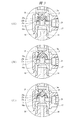
弁室23内には弁体25が配置されており、弁体25は中央部の基部25aと、この基部25aの外側の環状フランジ部25bとを有し、弁体25はゴム材料により一体に成形されている。基部25aは内側弁座面24に接触する位置と離れる位置とに移動して内側弁座面24を開閉し、環状フランジ部25bは弾性変形して外側弁座面21を開閉する。
A
外側弁座面21と円筒状の仕切り部材22は同軸状に配置されている。従って、仕切り部材22の先端側部に設けられる内側弁座面24も外側弁座面21に対して同軸となっている。弁体25は図2,図3(A)(B)(C)に示すように軸対称となっており、外側弁座面21と円筒状の仕切り部材22と内側弁座面24に対して同軸状に配置されている。これらの同軸配置により、弁体25の環状フランジ部25bと基部25aはそれぞれ確実に外側弁座面21と内側弁座面24を閉じることができる。
The outer
流路切換弁13の注入側部15には、収納容器11が取り外し自在に装着されるホルダー26が取り付けられている。一方、吐出側部16には吐出ノズル12の吐出配管14が接続される継手27が取り付けられている。
A
流路切換弁13のバルブケース18を構成するジョイント部17には、仕切り部材22の外側の環状の供給室17aに連通する連通孔28が形成されており、この連通孔28は供給室17aおよび吐出室16aに対して中心軸が直角となっている。ジョイント部17には連通管31の一端部がねじ結合され、連通管31の他端部は吐出制御ブロック32にねじ結合されている。吐出制御ブロック32は連通管31によりバルブケース18に連結されている。吐出制御ブロック32には注入側部15と平行な方向に延びる制御流路33が形成されており、この制御流路33内には収納容器11内のグリスGが注入室15a、弁室23,供給室17a、連通孔28および連通管31内の貫通孔31aを介して充填される。連通管31とジョイント部17の間をシールするために、シール部材34aがナット35aによりジョイント部17の端面に締結されている。連通管31と吐出制御ブロック32の間をシールするために、シール部材34bがナット35bにより吐出制御ブロック32の端面に締結されている。
The
収納容器11内のグリスGを制御流路33内に充填し、充填されたグリスGを制御流路33内から吐出室16aを介して吐出ノズル12に供給するために、吐出制御ブロック32には制御流路33内を往復動する吐出ロッド36が設けられている。この吐出ロッド36は吐出制御ブロック32に取り付けられる駆動ケース37内に組み込まれている。
In order to fill the
駆動ケース37は円筒部37aとこの基端部側の底壁部37bと先端部側の装着筒部37cとを有している。装着筒部37cには、吐出制御ブロック32に設けられた雄ねじ38aにねじ結合される雌ねじ38bが設けられている。円筒部37a内に設けられたスリーブ41には摺動部材42aが軸方向に往復動自在に挿入されており、この摺動部材42aの一端部には駆動ケース37の底壁部37bから外部に突出する駆動ロッド42が設けられている。吐出ロッド36は摺動部材42aに設けられており、駆動ロッド42を軸方向に駆動すると、吐出ロッド36が軸方向に駆動される。このように、駆動ロッド42とこれを往復動自在に収容する駆動ケース37は、吐出ロッド36を往復動する吐出手段となっている。駆動ケース37の先端部内にはカバー43が組み込まれており、カバー43の端壁部43aを吐出ロッド36が貫通して吐出制御ブロック32の制御流路33内に入り込んでいる。
The
カバー43の端壁部43aと摺動部材42aの間には、圧縮コイルばね44が装着されている。この圧縮コイルばね44からなるばね部材により、吐出ロッド36には制御流路33内から離れる後退方向のばね力が加えられている。吐出ロッド36が後退移動して制御流路33内から外部に突出する方向に移動すると、制御流路33の容積が拡大する。これに対し、吐出ロッド36をばね力に抗して前進移動させ制御流路33内に吐出ロッド36を進入させると、制御流路33の容積が縮小する。吐出ロッド36と吐出制御ブロック32との間をシールするために、吐出制御ブロック32にはシール材45が装着されている。シール材45は止めリング46により抜けが防止されている。
A
上述したグリスの吐出装置10を用いて被塗布物に対してグリスGを塗布する操作は、X,Yの2軸方向に移動する図示しない支持台に吐出装置10を据え付けて行うようにしても良く、被塗布物を移動させて固定された支持台に据え付けられた吐出装置10によりグリスGを塗布するようにしても良い。さらには、作業者が吐出装置10を手に持って塗布作業を行うようにしても良い。
The operation of applying the grease G to the object to be coated using the above-described
吐出装置10を支持台に取り付けるために、駆動ケース37の円筒部37aに形成された雄ねじ部にはナット47がねじ結合されており、このナット47により固定される図示しないブラケットにより支持台に吐出装置10が取り付けられる。収納容器11内のグリスGが確実に注入室15aに供給されるように、収納容器11にはその上端部から圧縮空気が図1において矢印で示すように供給されるようになっている。
In order to attach the
上述した吐出装置10により吐出ノズル12から被塗布物にグリスGを塗布するには、まず、駆動ロッド42が下端まで押し下げられて吐出ロッド36が制御流路33に入りきった状態から、収納容器11内のグリスGを制御流路33内に充填する。充填動作は、圧縮コイルばね44により吐出ロッド36を後退移動させて制御流路33の容積を膨張させることで行われる。また、吐出ロッド36の径が大きい場合には圧縮コイルばね44がなくても、収納容器11のグリスGに加えられる圧縮空気の圧力で吐出ロッド36を後退移動して、以下の充填動作が行われる。この充填動作のときには、注入室15aから弁室23にかけて圧力が連通孔28から制御流路33にかけての圧力よりも高いので、図3(A)に示されるように、弁体25の基部25aが内側弁座面24に密着してこれを閉じ、環状フランジ部25bが弾性変形して外側弁座面21から離れてこれを開くことになる。制御流路33へのグリスGの充填動作においては、収納容器11内には圧縮空気の圧力が加えられているので、吐出ロッド36の充填ストロークに対応した量のグリスGが制御流路33内に充填される。
In order to apply the grease G to the application object from the
この状態のもとで、吐出ロッド36が後退限位置まで後退移動して停止すると、注入室15aと供給室17aの圧力が釣り合ったバランス状態となる。このバランス状態となると、環状フランジ部25bが弾性力で元の形に戻って外側弁座面21に密着してこれを閉じるバランス動作が行われる。図2は吐出ロッド36を後退限位置まで駆動して制御流路33内へのグリスGの充填が完了したバランス動作状態を示す。
Under this state, when the
次いで、吐出ノズル12に向けて制御流路33内のグリスGを吐出供給するには、吐出ロッド36を前進移動させて制御流路33を収縮させる。この供給動作は、吐出装置10を自動的に作動させるときには、図示しない空気圧シリンダ等の往復動機構により駆動ロッド42を前進移動させることにより行う。一方、手動で吐出装置10を駆動する場合には、作業者が手作業で駆動ロッド42を押し込むことにより供給動作が行われる。いずれの駆動方式においても、制御流路33内へのグリスGの供給量は、駆動ロッド42の前進移動ストロークにより定まる。
Next, in order to discharge and supply the grease G in the
吐出ロッド36を前進移動させて供給動作が行われると、吐出ロッド36による制御流路33内のグリスGの圧力が注入室15a内のグリスGの圧力よりも高くなるので、弁体25の環状フランジ部25bは外側弁座面21に密着してこれを閉じた状態が維持される。一方、弁体25は、環状フランジ部25bを外側弁座面21に摺動させながら注入室15a側へわずかに移動し、その移動によって基部25aは内側弁座面24からわずかに離れてこれを開く。これにより、制御流路33内のグリスGは吐出室16a、継手27、および吐出配管14を通って吐出ノズル12から被塗布物に対して吐出される。
When the supply operation is performed by moving the
図3(B),図3(C)はいずれもグリスを吐出ノズル12から吐出させるグリス供給動作が行われているときの弁体25の開閉状態を示す。弁体25の基部25aの開度、つまり基部25aと内側弁座面24との間の隙間は、環状フランジ部25bがその弾性復元力により外側弁座面21を閉じた状態のもとで、制御流路33からの吐出室16aに向けて供給されるグリスGの流量に応じて変化することになる。図3(B)は制御流路33から吐出ノズル12に供給されるグリスGの供給速度が比較的速い場合を示し、図3(C)は供給されるグリスGの供給速度が比較的遅い場合を示す。このように、弁体25は軸方向移動により内側弁座面24を開閉する基部25aと、弾性変形と弾性復元により外側弁座面21を開閉するとともに基部25aの開度に応じて外側弁座面21を摺動接触する環状フランジ部25bとを有しているので、グリスGの吐出速度が遅い場合でも吐出ロッド36の供給動作ストロークに応じた量のグリスGを吐出ノズル12に供給することができる。
3B and 3C show the open / close state of the
吐出ロッド36は、収納容器11内のグリスGを制御流路33内に充填するときには、コイルばね44のばね力により後退移動される。この後退移動時には収納容器11内に加えられる圧縮空気の圧力により注入室15aにはグリスGに充填方向の圧力が加えられているので、ばね力を大きくすることなく、吐出ロッド36を後退限位置まで移動させることができる。
The
吐出ロッド36は駆動ケース37内に組み込まれている。駆動ケース37の装着筒部37cの雌ねじ38bを吐出制御ブロック32の雄ねじ38aにねじ結合することにより、吐出ロッド36が組み込まれた駆動ケース37を吐出制御ブロック32に取り付けることができる。図4は駆動ケース37を吐出制御ブロック32に取り付ける直前の状態を示す図であり、グリスGが連通管31の貫通孔31aを介して制御流路33内に充填された状態のもとで、装着筒部37cの雌ねじ38bを雄ねじ38aにねじ結合させる。つまり、初めて吐出装置10を使用する際には、制御流路33を上向きにし、駆動ケース37を取り外した状態で収納容器11をホルダー26に取り付け、わずかな圧力の圧縮空気でグリスGを注入室15aに供給し、バルブケース18,連通管31,シール材45,止めリング46まで充填する。グリスGは止めリング46からわずかに盛り上がった状態とする。これにより、これらの中に入っていた空気を止めリング46の口元から大気に放出し、エア抜きが完了する。エア抜きが完了したところに図4に示すように駆動ケース37を取り付けると、止めリング46からわずかに盛り上がったグリスG内に吐出ロッド36は入って行くので、空気が制御流路33内に入り込むことがない。
The
装着筒部37cを吐出制御ブロック32に取り付けるときに、装着筒部37cの内部つまり雌ねじ38bの内部に入り込んでいる空気を排出するために、装着筒部37cには排気孔51が形成されている。さらに、カバー43の端壁部43aには排出される空気を案内するために排気ガイド溝52が径方向に形成されている。このように、駆動ケース37を吐出制御ブロック32に取り付ける際には、装着筒部37cには排気孔51が形成されており、端壁部43aの外面には排気ガイド溝52が形成されているので、駆動ケース37を吐出制御ブロック32に取り付ける時には、空気が制御流路33内に入り込むことを防止できる。また、吐出ロッド36はコイルばね44により引っ込んだ状態となっているので、その操作を容易に行うことができる。
When the mounting
図5はグリスの吐出装置の変形例を示す一部省略断面図であり、図5にはグリスの吐出装置における図4と同様の部分が示されている。 FIG. 5 is a partially omitted cross-sectional view showing a modified example of the grease discharge device. FIG. 5 shows the same portion of the grease discharge device as in FIG.
この吐出装置においては、駆動ケース37の円筒部37aに形成されたおねじ部には、円筒形状のストローク調整部材53がねじ結合されている。このストローク調整部材53は回転により駆動ケース37の軸方向任意に位置決めすることができ、ナット47をストローク調整部材53に締め付けると、ストローク調整部材53は所定の位置で固定される。駆動ロッド42にはストローク調整部材53の端面に当接する大径のストッパ54が設けられている。駆動ロッド42の往復動ストロークは、ストローク調整部材53の端面とストッパ54の距離により設定され、駆動ロッド42の往復動ストロークにより吐出ロッド36の往復動ストロークが設定される。このように、制御流路33内へのグリスGの供給量は、駆動ロッド42の前進移動ストロークにより定まることになる、したがって、ストローク調整部材53の駆動ケース37に対する軸方向位置を調整することによって、吐出ロッド36によるグリスGの供給量を調整することができる。
In this discharge device, a cylindrical
本発明は前記実施の形態に限定されるものではなく、その要旨を逸脱しない範囲で種々変更可能である。 The present invention is not limited to the above-described embodiment, and various modifications can be made without departing from the scope of the invention.
11 収納容器
12 吐出ノズル
13 流路切換弁
15 注入側部
15a 注入室
16 吐出側部
16a 吐出室
17 ジョイント部
17a 供給室
18 バルブケース
21 外側弁座面
22 仕切り部材
23 弁室
24 内側弁座面
25 弁体
25a 基部
25b 環状フランジ部
31 連通管
31a 貫通孔
32 吐出制御ブロック
33 制御流路
36 吐出ロッド
37 駆動ケース
37c 装着筒部
42 駆動ロッド
44 圧縮コイルばね
46 止めリング
51 排気孔
52 排気ガイド溝
G グリス
DESCRIPTION OF
Claims (4)
前記外側弁座面の径方向内方に配置され内側の吐出室と外側の供給室とを仕切る円筒形状の仕切り部材と、
前記仕切り部材の先端側部に設けられ前記外側弁座面との間で弁室を区画する内側弁座面と、
前記供給室に連通するとともに吐出ロッドによって容積変化する制御流路が形成された吐出制御ブロックと、
前記弁室内に配置され前記内側弁座面を開閉する基部、および当該基部に一体に設けられ弾性変形によって前記外側弁座面を開閉する環状フランジ部を有する弁体と、
を有し、
前記弁体が前記内側弁座面に接触し、前記環状フランジ部が前記外側弁座面に当接する第1状態と、
前記弁体が前記内側弁座面に当接し、前記環状フランジ部が前記外側弁座面から離れる第2状態と、
前記弁体が前記内側弁座面から離れ、前記環状フランジ部が前記外側弁座面に当接する第3状態と、
に作動し、
流動性材料を吐出具に案内する案内流路を切り換える流路切換弁であって、
前記吐出ロッドが後退することで、前記弁体を前記第2状態として前記注入室から前記制御流路へ流動性材料を移動させる充填動作と、
前記吐出ロッドが前進し前記供給室の圧力が高まることで、前記弁体を前記第3状態として前記制御流路から前記吐出室への流動性材料を移動させて吐出口から吐出させる吐出動作と、
が行われ、前記吐出動作後には前記吐出ロッドが後退位置に移動し、流動性材料が前記制御流路内に充填された状態で、加圧状態の流動性材料によって、前記弁体は前記第1状態に移行することを特徴とする流路切換弁。 An injection chamber to which a flowable material pressurized with compressed air is supplied, and a cylindrical outer valve seat surface connected to the injection chamber;
A cylindrical partition member that is arranged radially inward of the outer valve seat surface and partitions the inner discharge chamber and the outer supply chamber;
An inner valve seat surface that is provided at a distal end side portion of the partition member and partitions a valve chamber with the outer valve seat surface;
A discharge control block in which a control flow path communicating with the supply chamber and changing in volume by a discharge rod is formed;
A valve body having a base portion disposed in the valve chamber for opening and closing the inner valve seat surface, and an annular flange portion integrally provided in the base portion for opening and closing the outer valve seat surface by elastic deformation;
Have
A first state in which the valve body is in contact with the inner valve seat surface, and the annular flange portion is in contact with the outer valve seat surface;
A second state in which the valve body abuts on the inner valve seat surface, and the annular flange portion is separated from the outer valve seat surface;
A third state in which the valve body is separated from the inner valve seat surface, and the annular flange portion is in contact with the outer valve seat surface;
Operated on
A flow path switching valve for switching a guide flow path for guiding a flowable material to a discharge tool,
A refilling operation for moving the flowable material from the injection chamber to the control flow path with the valve body in the second state by retreating the discharge rod;
A discharge operation in which the discharge rod moves forward and the pressure in the supply chamber is increased, so that the valve body is moved to the third state to move the flowable material from the control flow path to the discharge chamber and discharge from the discharge port. ,
After the discharge operation, the discharge rod moves to the retracted position, and the valve body is moved by the pressurized flowable material while the flowable material is filled in the control flow path . 1. A flow path switching valve that shifts to one state.
前記外側弁座面の径方向内方に配置され内側の吐出室と外側の供給室とを仕切る円筒形状の仕切り部材と、
前記仕切り部材の先端側部に設けられ前記外側弁座面との間で弁室を区画する内側弁座面と、
前記供給室に連通するとともに吐出ロッドによって容積変化する制御流路が形成された吐出制御ブロックと、
前記吐出制御ブロックに設けられ、前記吐出ロッドを往復動する吐出手段と、
前記弁室内に配置され前記内側弁座面を開閉する基部、および当該基部に一体に設けられ弾性変形によって前記外側弁座面を開閉する環状フランジ部を有する弁体と、
を有し、
前記弁体が前記内側弁座面に接触し、前記環状フランジ部が前記外側弁座面に当接する第1状態と、
前記弁体が前記内側弁座面に当接し、前記環状フランジ部が前記外側弁座面から離れる第2状態と、
前記弁体が前記内側弁座面から離れ、前記環状フランジ部が前記外側弁座面に当接する第3状態と、
に作動し、
流動性材料を吐出具に吐出する流動性材料の吐出制御装置であって、
前記吐出ロッドが後退することで、前記弁体を前記第2状態として前記注入室から前記制御流路へ流動性材料を移動させる充填動作と、
前記吐出ロッドが前進し、前記供給室の圧力が高まることで、前記弁体を前記第3状態として前記制御流路から前記吐出室への流動性材料を移動させて吐出口から吐出させる吐出動作と、
が行われ、前記吐出動作後には前記吐出ロッドが後退位置に移動し、流動性材料が前記制御流路内に充填された状態で、加圧状態の流動性材料によって、前記弁体は前記第1状態に移行することを特徴とする流動性材料の吐出制御装置。 An injection chamber to which a flowable material pressurized with compressed air is supplied, and a cylindrical outer valve seat surface connected to the injection chamber;
A cylindrical partition member that is arranged radially inward of the outer valve seat surface and partitions the inner discharge chamber and the outer supply chamber;
An inner valve seat surface that is provided at a distal end side portion of the partition member and partitions a valve chamber with the outer valve seat surface;
A discharge control block in which a control flow path communicating with the supply chamber and changing in volume by a discharge rod is formed;
A discharge means provided in the discharge control block for reciprocating the discharge rod;
A valve body having a base portion disposed in the valve chamber for opening and closing the inner valve seat surface, and an annular flange portion integrally provided in the base portion for opening and closing the outer valve seat surface by elastic deformation;
Have
A first state in which the valve body is in contact with the inner valve seat surface, and the annular flange portion is in contact with the outer valve seat surface;
A second state in which the valve body abuts on the inner valve seat surface, and the annular flange portion is separated from the outer valve seat surface;
A third state in which the valve body is separated from the inner valve seat surface, and the annular flange portion is in contact with the outer valve seat surface;
Operated on
A discharge control device for a flowable material that discharges the flowable material to a discharge tool,
A refilling operation for moving the flowable material from the injection chamber to the control flow path with the valve body in the second state by retreating the discharge rod;
As the discharge rod moves forward and the pressure in the supply chamber increases, the discharge operation is performed by moving the flowable material from the control flow path to the discharge chamber with the valve body in the third state and discharging from the discharge port. When,
After the discharge operation, the discharge rod moves to the retracted position, and the valve body is moved by the pressurized flowable material while the flowable material is filled in the control flow path . A flowable material discharge control device, wherein the flowable material transitions to one state.
Priority Applications (4)
| Application Number | Priority Date | Filing Date | Title |
|---|---|---|---|
| JP2011192486A JP5535155B2 (en) | 2011-09-05 | 2011-09-05 | Flow path switching valve and fluid material discharge control device using the same |
| US13/602,806 US9133943B2 (en) | 2011-09-05 | 2012-09-04 | Flow path switching valve and discharge control apparatus for fluid material using the same |
| DE201210108199 DE102012108199A1 (en) | 2011-09-05 | 2012-09-04 | Flow path switching valve and fluid material discharge control device using the same |
| CN2012103265819A CN103062437A (en) | 2011-09-05 | 2012-09-05 | Flow path switching valve and discharge control apparatus for fluid material using the same |
Applications Claiming Priority (1)
| Application Number | Priority Date | Filing Date | Title |
|---|---|---|---|
| JP2011192486A JP5535155B2 (en) | 2011-09-05 | 2011-09-05 | Flow path switching valve and fluid material discharge control device using the same |
Publications (3)
| Publication Number | Publication Date |
|---|---|
| JP2013053684A JP2013053684A (en) | 2013-03-21 |
| JP2013053684A5 JP2013053684A5 (en) | 2013-05-30 |
| JP5535155B2 true JP5535155B2 (en) | 2014-07-02 |
Family
ID=47740319
Family Applications (1)
| Application Number | Title | Priority Date | Filing Date |
|---|---|---|---|
| JP2011192486A Active JP5535155B2 (en) | 2011-09-05 | 2011-09-05 | Flow path switching valve and fluid material discharge control device using the same |
Country Status (4)
| Country | Link |
|---|---|
| US (1) | US9133943B2 (en) |
| JP (1) | JP5535155B2 (en) |
| CN (1) | CN103062437A (en) |
| DE (1) | DE102012108199A1 (en) |
Families Citing this family (6)
| Publication number | Priority date | Publication date | Assignee | Title |
|---|---|---|---|---|
| JP5535155B2 (en) * | 2011-09-05 | 2014-07-02 | 株式会社コガネイ | Flow path switching valve and fluid material discharge control device using the same |
| US10384841B2 (en) * | 2017-06-29 | 2019-08-20 | Norman Werbner Information Services, Inc. | Liquid extraction, storage, and dispensing system and method of use |
| TWM559852U (en) * | 2018-01-23 | 2018-05-11 | Horng Chang Metal Industrial Co Ltd | Edible liquid container pressing device |
| KR102396285B1 (en) | 2018-02-14 | 2022-05-10 | 외티커 슈비츠 아게 | flow path diverter valve |
| DE102018131567A1 (en) * | 2018-12-10 | 2020-06-10 | Vermes Microdispensing GmbH | Dosing system and method for controlling a dosing system |
| CN116899820B (en) * | 2023-09-14 | 2024-01-02 | 常州银河世纪微电子股份有限公司 | Double-hole dispensing head for chip and dispensing method thereof |
Family Cites Families (81)
| Publication number | Priority date | Publication date | Assignee | Title |
|---|---|---|---|---|
| US3086542A (en) * | 1960-03-23 | 1963-04-23 | Kenneth C Mosier | Air valve |
| SE205191C1 (en) * | 1961-07-04 | 1966-06-07 | Aga Ab | Valves for respirators |
| US3270771A (en) * | 1963-06-11 | 1966-09-06 | Robertshaw Controls Co | Resilient disc check valve |
| US3419031A (en) * | 1965-03-15 | 1968-12-31 | Hesse | Breathing valve |
| JPS4842339Y1 (en) * | 1970-07-14 | 1973-12-08 | ||
| US4084606A (en) * | 1974-04-23 | 1978-04-18 | Baxter Travenol Laboratories, Inc. | Fluid transfer device |
| US4006847A (en) * | 1975-10-23 | 1977-02-08 | Dooley Dynamics, Inc. | Dispensing apparatus |
| JPS5362929U (en) * | 1976-10-29 | 1978-05-27 | ||
| AU522423B2 (en) * | 1978-03-07 | 1982-06-03 | Commonwealth Industrial Gases Limited, The | Artificial respirator valve system |
| JPS5526663U (en) * | 1978-08-09 | 1980-02-21 | ||
| US4305531A (en) * | 1978-09-21 | 1981-12-15 | Dooley Dan W | Pneumatically operated controlled volume dispensing device |
| US4235265A (en) * | 1979-03-05 | 1980-11-25 | The Mead Corporation | Aseptic container filler apparatus |
| US4254806A (en) * | 1979-04-25 | 1981-03-10 | Robert M. Elsworth | Apparatus for filling caulking tubes in a clean manner |
| US4246932A (en) * | 1979-10-18 | 1981-01-27 | Burron Medical, Inc. | Multiple additive valve assembly |
| US4793524A (en) * | 1981-04-30 | 1988-12-27 | American Monitor Corporation | Integrated reagent container and metered dispenser means |
| US4438872A (en) * | 1981-07-20 | 1984-03-27 | Dooley Dan W | Dispensing apparatus |
| US4485971A (en) * | 1982-04-05 | 1984-12-04 | Paul D Pajevic | Liquid sprayer |
| US4456152A (en) * | 1982-05-03 | 1984-06-26 | Young Don H | Measuring and dispensing apparatus |
| US4457330A (en) * | 1983-02-11 | 1984-07-03 | Yardney Corporation | Reversible quick exhaust valve |
| US4634027A (en) * | 1985-01-04 | 1987-01-06 | Mvm Valve Co., Inc. | Liquid dispensing apparatus and an anti-drip valve cartridge therefor |
| JPS62190171A (en) | 1986-02-14 | 1987-08-20 | Ube Ind Ltd | Novel sulfonylurea derivative and herbicide |
| US4666429A (en) * | 1986-02-26 | 1987-05-19 | Intelligent Medicine, Inc. | Infusion device having improved valving apparatus |
| JPS62190171U (en) * | 1986-05-26 | 1987-12-03 | ||
| US4905744A (en) * | 1987-07-23 | 1990-03-06 | Elopak A/S | Liquid-flow control apparatus |
| US4869404A (en) * | 1987-11-23 | 1989-09-26 | American Wyott Corporation | Condiment pump |
| US5054656A (en) * | 1989-04-14 | 1991-10-08 | Lasner Jeffrey I | Fluid container with pump and attached dosage dispenser |
| DE4014760A1 (en) * | 1990-05-08 | 1991-11-14 | Electronal Ges Fuer Elektronik | DISPENSER HEAD FOR APPLYING SMALL QUANTITIES OF A PASTOUS DIMENSION FOR THE SURFACE MOUNTING OF ELECTRONIC COMPONENTS |
| US5038814A (en) * | 1990-06-15 | 1991-08-13 | Moen Incorporated | Back flow preventer and integral vacuum breaker |
| US5098405A (en) * | 1991-01-31 | 1992-03-24 | Becton, Dickinson And Company | Apparatus and method for a side port cathether adapter with a one piece integral combination valve |
| US5176658A (en) * | 1991-05-03 | 1993-01-05 | Sherwood Medical Company | Valve assembly for use in medical devices |
| DE69204760T2 (en) * | 1991-06-24 | 1996-04-25 | Smc Kk | Speed control. |
| JP2788809B2 (en) * | 1991-06-24 | 1998-08-20 | エスエムシー 株式会社 | speed controller |
| US5320250A (en) * | 1991-12-02 | 1994-06-14 | Asymptotic Technologies, Inc. | Method for rapid dispensing of minute quantities of viscous material |
| US5360413A (en) * | 1991-12-06 | 1994-11-01 | Filtertek, Inc. | Needleless access device |
| JPH06101636A (en) * | 1992-09-19 | 1994-04-12 | Denzaburo Nakaya | Shifting device by reciprocating pump |
| US5295478A (en) * | 1993-02-16 | 1994-03-22 | Baldwin Gene R | Mouth-to-mask resuscitator |
| US5375746A (en) * | 1993-05-10 | 1994-12-27 | Server Products, Inc. | Food pump having a cast valve body |
| AUPM290893A0 (en) * | 1993-12-13 | 1994-01-13 | Mcinnes, Gregory Charles | Vending device for paste-like substances |
| US5407102A (en) * | 1994-02-15 | 1995-04-18 | Freudinger; Mark J. | Apparatus for dispensing a quantity of flowable material |
| US5579959A (en) * | 1995-05-16 | 1996-12-03 | Star Manufacturing International, Inc. | Viscous food products housing, pump, dispenser, and valve apparatus |
| US6253957B1 (en) * | 1995-11-16 | 2001-07-03 | Nordson Corporation | Method and apparatus for dispensing small amounts of liquid material |
| US5738662A (en) * | 1996-02-21 | 1998-04-14 | Pacific Device/Avail Medical Products, Inc. | Retrograde flow checked manifold for infusing medical fluids |
| US5916524A (en) * | 1997-07-23 | 1999-06-29 | Bio-Dot, Inc. | Dispensing apparatus having improved dynamic range |
| JP3554115B2 (en) * | 1996-08-26 | 2004-08-18 | 株式会社コガネイ | Chemical supply device |
| US5749358A (en) * | 1996-10-10 | 1998-05-12 | Nellcor Puritan Bennett Incorporated | Resuscitator bag exhaust port with CO2 indicator |
| US6290682B1 (en) * | 1997-02-13 | 2001-09-18 | Filterek Inc. | Infusion set |
| US6085943A (en) * | 1997-06-30 | 2000-07-11 | Speedline Technologies, Inc. | Controllable liquid dispensing device |
| US6085773A (en) * | 1997-12-05 | 2000-07-11 | Karg; Jeffrey A. | Automatic fluid switching valve |
| GB9820962D0 (en) * | 1998-09-25 | 1998-11-18 | English Glass Company The Limi | Dispenser pumps |
| AU1123300A (en) * | 1998-10-16 | 2000-05-08 | Micro Robotics Systems, Inc. | Dispensing apparatus |
| DE19929607C1 (en) * | 1999-06-28 | 2000-11-23 | Jan Willem Marinus Myers | Two-way valve comprises an additional clamping zone which is located between the outer annular clamped rim and the inner annular seating surface of the membrane disk, for use in e.g. a liquid dispenser |
| US6453940B1 (en) * | 1999-12-20 | 2002-09-24 | Federal-Mogul Corporation | Insert bonded combination valve |
| JP2001278388A (en) * | 2000-03-31 | 2001-10-10 | Toyo Jidoki Co Ltd | Rotary continuous filling device |
| US6378740B1 (en) * | 2000-06-16 | 2002-04-30 | Mush, Inc. | Portable frozen beverage dispenser |
| US8915722B1 (en) * | 2009-02-23 | 2014-12-23 | George H. Blume | Integrated fluid end |
| US6343720B1 (en) * | 2000-09-22 | 2002-02-05 | Carlisle Foodservice Products, Incorporated | Condiment pump |
| JP2002147625A (en) | 2000-11-14 | 2002-05-22 | Hitachi Valve Ltd | Three-way check valve |
| JP2002239435A (en) * | 2001-02-16 | 2002-08-27 | Matsushita Electric Ind Co Ltd | Apparatus and method for applying viscous material |
| JP2002349348A (en) * | 2001-05-18 | 2002-12-04 | Walbro Japan Inc | Accelerating pump of float type carburetor |
| JP4183411B2 (en) * | 2001-11-02 | 2008-11-19 | アピックヤマダ株式会社 | Liquid material discharge device |
| US6983867B1 (en) * | 2002-04-29 | 2006-01-10 | Dl Technology Llc | Fluid dispense pump with drip prevention mechanism and method for controlling same |
| WO2004014566A1 (en) * | 2002-08-06 | 2004-02-19 | Glaxo Group Limited | A dispenser |
| US6953450B2 (en) * | 2002-08-22 | 2005-10-11 | Baxa Corporation | Apparatus and method for administration of IV liquid medication and IV flush solutions |
| US6814109B2 (en) * | 2003-01-03 | 2004-11-09 | Packaging Technologies, Inc. | Zero clearance rotor valve for product filling |
| JP2004283714A (en) * | 2003-03-20 | 2004-10-14 | Fujitsu Display Technologies Corp | Liquid delivery dispenser |
| CN100439820C (en) * | 2003-07-14 | 2008-12-03 | 诺信公司 | Apparatus and method for dispensing discrete amounts of viscous material |
| GB0320883D0 (en) * | 2003-09-05 | 2003-10-08 | Brightwell Dispensers Ltd | Fluid pump |
| US7712637B2 (en) * | 2003-12-11 | 2010-05-11 | Gregory Lambrecht | Wine extraction and preservation device and method |
| JP2005230299A (en) * | 2004-02-20 | 2005-09-02 | Katsutoshi Masuda | Fluid storage vessel |
| US7600530B2 (en) * | 2004-08-09 | 2009-10-13 | Medegen, Inc. | Connector with check valve and method of use |
| JP4711328B2 (en) * | 2005-01-18 | 2011-06-29 | 武蔵エンジニアリング株式会社 | Liquid ejection method and apparatus |
| US7621429B2 (en) * | 2006-02-27 | 2009-11-24 | Aerojet- General Corporation | Piston tank with compound piston for high loading and expulsion efficiency |
| US7793804B2 (en) * | 2006-04-20 | 2010-09-14 | Chapin Manufacturing, Inc. | Reservoir pump |
| JP4547369B2 (en) * | 2006-11-29 | 2010-09-22 | 株式会社コガネイ | Chemical supply device |
| US8690870B2 (en) * | 2006-12-28 | 2014-04-08 | St. Jude Medical, Atrial Fibrillation Division, Inc. | Irrigated ablation catheter system with pulsatile flow to prevent thrombus |
| US8337470B2 (en) * | 2009-01-28 | 2012-12-25 | Angiodynamics, Inc. | Three-way valve for power injection in vascular access devices |
| JP5419616B2 (en) * | 2009-09-25 | 2014-02-19 | 武蔵エンジニアリング株式会社 | Bubble mixing prevention mechanism, liquid material discharging apparatus including the mechanism, and liquid material discharging method |
| JP5444051B2 (en) | 2010-03-12 | 2014-03-19 | スタンレー電気株式会社 | Vehicle lighting |
| US9346075B2 (en) * | 2011-08-26 | 2016-05-24 | Nordson Corporation | Modular jetting devices |
| JP5535155B2 (en) * | 2011-09-05 | 2014-07-02 | 株式会社コガネイ | Flow path switching valve and fluid material discharge control device using the same |
| US8708246B2 (en) * | 2011-10-28 | 2014-04-29 | Nordson Corporation | Positive displacement dispenser and method for dispensing discrete amounts of liquid |
-
2011
- 2011-09-05 JP JP2011192486A patent/JP5535155B2/en active Active
-
2012
- 2012-09-04 DE DE201210108199 patent/DE102012108199A1/en active Pending
- 2012-09-04 US US13/602,806 patent/US9133943B2/en active Active
- 2012-09-05 CN CN2012103265819A patent/CN103062437A/en active Pending
Also Published As
| Publication number | Publication date |
|---|---|
| US20130068330A1 (en) | 2013-03-21 |
| US9133943B2 (en) | 2015-09-15 |
| CN103062437A (en) | 2013-04-24 |
| JP2013053684A (en) | 2013-03-21 |
| DE102012108199A1 (en) | 2013-03-14 |
Similar Documents
| Publication | Publication Date | Title |
|---|---|---|
| JP5535155B2 (en) | Flow path switching valve and fluid material discharge control device using the same | |
| EP3124430B1 (en) | Slide valve for liquid injecting container | |
| JP6199553B2 (en) | Positive displacement dispenser and method for discharging individual amounts of liquid | |
| US8333307B2 (en) | Liquid dispensing module | |
| US6715506B1 (en) | Method and device for injecting a fixed quantity of liquid | |
| JP5100074B2 (en) | Pneumatic delivery system and method using linear actuation | |
| KR101945788B1 (en) | Fluid pressure cylinder | |
| KR20070078699A (en) | Liquid chemical supply system | |
| JP2007532298A (en) | Liquid discharge valve, improved stroke length calibration method, and fluid fitting | |
| KR20020035441A (en) | Two-way valve | |
| US20070221126A1 (en) | Chemical Liquid Supply Apparatus | |
| KR101625337B1 (en) | Spray valve for high viscous fluid | |
| KR101418529B1 (en) | Liquid supplying method and device | |
| KR20190143825A (en) | Dispensing nozzle for a coater | |
| JP2001113212A (en) | Liquid jetting apparatus | |
| JP2006194298A (en) | Diaphragm valve | |
| EP3431187B1 (en) | Device for dispensing a plurality of fluid products | |
| JP2017530860A (en) | Non-impact jetting discharge module and method | |
| JPS6312292Y2 (en) | ||
| KR20030044839A (en) | A dispenser for liquid ejection | |
| JP7229507B2 (en) | Valve device and liquid filling device | |
| US11199187B2 (en) | Plunger pump | |
| JP2017002939A (en) | Fluid control valve | |
| JP2005103507A (en) | Apparatus for preventing dripping of liquid from coating gun | |
| KR20160053384A (en) | Apparatus for discharging fixed quantity of liquid |
Legal Events
| Date | Code | Title | Description |
|---|---|---|---|
| A521 | Request for written amendment filed |
Free format text: JAPANESE INTERMEDIATE CODE: A523 Effective date: 20130410 |
|
| A621 | Written request for application examination |
Free format text: JAPANESE INTERMEDIATE CODE: A621 Effective date: 20130410 |
|
| A977 | Report on retrieval |
Free format text: JAPANESE INTERMEDIATE CODE: A971007 Effective date: 20130809 |
|
| A131 | Notification of reasons for refusal |
Free format text: JAPANESE INTERMEDIATE CODE: A131 Effective date: 20130813 |
|
| A521 | Request for written amendment filed |
Free format text: JAPANESE INTERMEDIATE CODE: A523 Effective date: 20131011 |
|
| TRDD | Decision of grant or rejection written | ||
| A01 | Written decision to grant a patent or to grant a registration (utility model) |
Free format text: JAPANESE INTERMEDIATE CODE: A01 Effective date: 20140408 |
|
| A61 | First payment of annual fees (during grant procedure) |
Free format text: JAPANESE INTERMEDIATE CODE: A61 Effective date: 20140422 |
|
| R150 | Certificate of patent or registration of utility model |
Ref document number: 5535155 Country of ref document: JP Free format text: JAPANESE INTERMEDIATE CODE: R150 |
|
| R250 | Receipt of annual fees |
Free format text: JAPANESE INTERMEDIATE CODE: R250 |
|
| R250 | Receipt of annual fees |
Free format text: JAPANESE INTERMEDIATE CODE: R250 |
|
| R250 | Receipt of annual fees |
Free format text: JAPANESE INTERMEDIATE CODE: R250 |
|
| R250 | Receipt of annual fees |
Free format text: JAPANESE INTERMEDIATE CODE: R250 |
|
| R250 | Receipt of annual fees |
Free format text: JAPANESE INTERMEDIATE CODE: R250 |
|
| R250 | Receipt of annual fees |
Free format text: JAPANESE INTERMEDIATE CODE: R250 |
|
| R250 | Receipt of annual fees |
Free format text: JAPANESE INTERMEDIATE CODE: R250 |
|
| R250 | Receipt of annual fees |
Free format text: JAPANESE INTERMEDIATE CODE: R250 |