JP5534720B2 - Blade manufacturing method - Google Patents
Blade manufacturing method Download PDFInfo
- Publication number
- JP5534720B2 JP5534720B2 JP2009148697A JP2009148697A JP5534720B2 JP 5534720 B2 JP5534720 B2 JP 5534720B2 JP 2009148697 A JP2009148697 A JP 2009148697A JP 2009148697 A JP2009148697 A JP 2009148697A JP 5534720 B2 JP5534720 B2 JP 5534720B2
- Authority
- JP
- Japan
- Prior art keywords
- steel strip
- manufacturing
- hard material
- blade
- blade according
- Prior art date
- Legal status (The legal status is an assumption and is not a legal conclusion. Google has not performed a legal analysis and makes no representation as to the accuracy of the status listed.)
- Expired - Fee Related
Links
Images


Classifications
-
- B—PERFORMING OPERATIONS; TRANSPORTING
- B23—MACHINE TOOLS; METAL-WORKING NOT OTHERWISE PROVIDED FOR
- B23P—METAL-WORKING NOT OTHERWISE PROVIDED FOR; COMBINED OPERATIONS; UNIVERSAL MACHINE TOOLS
- B23P15/00—Making specific metal objects by operations not covered by a single other subclass or a group in this subclass
- B23P15/28—Making specific metal objects by operations not covered by a single other subclass or a group in this subclass cutting tools
- B23P15/40—Making specific metal objects by operations not covered by a single other subclass or a group in this subclass cutting tools shearing tools
-
- B—PERFORMING OPERATIONS; TRANSPORTING
- B23—MACHINE TOOLS; METAL-WORKING NOT OTHERWISE PROVIDED FOR
- B23D—PLANING; SLOTTING; SHEARING; BROACHING; SAWING; FILING; SCRAPING; LIKE OPERATIONS FOR WORKING METAL BY REMOVING MATERIAL, NOT OTHERWISE PROVIDED FOR
- B23D65/00—Making tools for sawing machines or sawing devices for use in cutting any kind of material
-
- B—PERFORMING OPERATIONS; TRANSPORTING
- B23—MACHINE TOOLS; METAL-WORKING NOT OTHERWISE PROVIDED FOR
- B23K—SOLDERING OR UNSOLDERING; WELDING; CLADDING OR PLATING BY SOLDERING OR WELDING; CUTTING BY APPLYING HEAT LOCALLY, e.g. FLAME CUTTING; WORKING BY LASER BEAM
- B23K15/00—Electron-beam welding or cutting
- B23K15/0046—Welding
- B23K15/0086—Welding welding for purposes other than joining, e.g. built-up welding
-
- B—PERFORMING OPERATIONS; TRANSPORTING
- B23—MACHINE TOOLS; METAL-WORKING NOT OTHERWISE PROVIDED FOR
- B23K—SOLDERING OR UNSOLDERING; WELDING; CLADDING OR PLATING BY SOLDERING OR WELDING; CUTTING BY APPLYING HEAT LOCALLY, e.g. FLAME CUTTING; WORKING BY LASER BEAM
- B23K15/00—Electron-beam welding or cutting
- B23K15/0046—Welding
- B23K15/0093—Welding characterised by the properties of the materials to be welded
-
- B—PERFORMING OPERATIONS; TRANSPORTING
- B23—MACHINE TOOLS; METAL-WORKING NOT OTHERWISE PROVIDED FOR
- B23K—SOLDERING OR UNSOLDERING; WELDING; CLADDING OR PLATING BY SOLDERING OR WELDING; CUTTING BY APPLYING HEAT LOCALLY, e.g. FLAME CUTTING; WORKING BY LASER BEAM
- B23K26/00—Working by laser beam, e.g. welding, cutting or boring
- B23K26/14—Working by laser beam, e.g. welding, cutting or boring using a fluid stream, e.g. a jet of gas, in conjunction with the laser beam; Nozzles therefor
- B23K26/144—Working by laser beam, e.g. welding, cutting or boring using a fluid stream, e.g. a jet of gas, in conjunction with the laser beam; Nozzles therefor the fluid stream containing particles, e.g. powder
-
- B—PERFORMING OPERATIONS; TRANSPORTING
- B23—MACHINE TOOLS; METAL-WORKING NOT OTHERWISE PROVIDED FOR
- B23K—SOLDERING OR UNSOLDERING; WELDING; CLADDING OR PLATING BY SOLDERING OR WELDING; CUTTING BY APPLYING HEAT LOCALLY, e.g. FLAME CUTTING; WORKING BY LASER BEAM
- B23K26/00—Working by laser beam, e.g. welding, cutting or boring
- B23K26/20—Bonding
- B23K26/32—Bonding taking account of the properties of the material involved
-
- B—PERFORMING OPERATIONS; TRANSPORTING
- B23—MACHINE TOOLS; METAL-WORKING NOT OTHERWISE PROVIDED FOR
- B23K—SOLDERING OR UNSOLDERING; WELDING; CLADDING OR PLATING BY SOLDERING OR WELDING; CUTTING BY APPLYING HEAT LOCALLY, e.g. FLAME CUTTING; WORKING BY LASER BEAM
- B23K26/00—Working by laser beam, e.g. welding, cutting or boring
- B23K26/34—Laser welding for purposes other than joining
-
- B—PERFORMING OPERATIONS; TRANSPORTING
- B23—MACHINE TOOLS; METAL-WORKING NOT OTHERWISE PROVIDED FOR
- B23K—SOLDERING OR UNSOLDERING; WELDING; CLADDING OR PLATING BY SOLDERING OR WELDING; CUTTING BY APPLYING HEAT LOCALLY, e.g. FLAME CUTTING; WORKING BY LASER BEAM
- B23K31/00—Processes relevant to this subclass, specially adapted for particular articles or purposes, but not covered by only one of the preceding main groups
- B23K31/02—Processes relevant to this subclass, specially adapted for particular articles or purposes, but not covered by only one of the preceding main groups relating to soldering or welding
- B23K31/025—Connecting cutting edges or the like to tools; Attaching reinforcements to workpieces, e.g. wear-resisting zones to tableware
-
- B—PERFORMING OPERATIONS; TRANSPORTING
- B23—MACHINE TOOLS; METAL-WORKING NOT OTHERWISE PROVIDED FOR
- B23K—SOLDERING OR UNSOLDERING; WELDING; CLADDING OR PLATING BY SOLDERING OR WELDING; CUTTING BY APPLYING HEAT LOCALLY, e.g. FLAME CUTTING; WORKING BY LASER BEAM
- B23K35/00—Rods, electrodes, materials, or media, for use in soldering, welding, or cutting
- B23K35/02—Rods, electrodes, materials, or media, for use in soldering, welding, or cutting characterised by mechanical features, e.g. shape
- B23K35/0222—Rods, electrodes, materials, or media, for use in soldering, welding, or cutting characterised by mechanical features, e.g. shape for use in soldering, brazing
- B23K35/0244—Powders, particles or spheres; Preforms made therefrom
-
- B—PERFORMING OPERATIONS; TRANSPORTING
- B23—MACHINE TOOLS; METAL-WORKING NOT OTHERWISE PROVIDED FOR
- B23K—SOLDERING OR UNSOLDERING; WELDING; CLADDING OR PLATING BY SOLDERING OR WELDING; CUTTING BY APPLYING HEAT LOCALLY, e.g. FLAME CUTTING; WORKING BY LASER BEAM
- B23K35/00—Rods, electrodes, materials, or media, for use in soldering, welding, or cutting
- B23K35/22—Rods, electrodes, materials, or media, for use in soldering, welding, or cutting characterised by the composition or nature of the material
- B23K35/24—Selection of soldering or welding materials proper
- B23K35/32—Selection of soldering or welding materials proper with the principal constituent melting at more than 1550 degrees C
- B23K35/327—Selection of soldering or welding materials proper with the principal constituent melting at more than 1550 degrees C comprising refractory compounds, e.g. carbides
-
- B—PERFORMING OPERATIONS; TRANSPORTING
- B23—MACHINE TOOLS; METAL-WORKING NOT OTHERWISE PROVIDED FOR
- B23P—METAL-WORKING NOT OTHERWISE PROVIDED FOR; COMBINED OPERATIONS; UNIVERSAL MACHINE TOOLS
- B23P15/00—Making specific metal objects by operations not covered by a single other subclass or a group in this subclass
- B23P15/28—Making specific metal objects by operations not covered by a single other subclass or a group in this subclass cutting tools
-
- B—PERFORMING OPERATIONS; TRANSPORTING
- B26—HAND CUTTING TOOLS; CUTTING; SEVERING
- B26D—CUTTING; DETAILS COMMON TO MACHINES FOR PERFORATING, PUNCHING, CUTTING-OUT, STAMPING-OUT OR SEVERING
- B26D1/00—Cutting through work characterised by the nature or movement of the cutting member or particular materials not otherwise provided for; Apparatus or machines therefor; Cutting members therefor
- B26D1/0006—Cutting members therefor
-
- C—CHEMISTRY; METALLURGY
- C22—METALLURGY; FERROUS OR NON-FERROUS ALLOYS; TREATMENT OF ALLOYS OR NON-FERROUS METALS
- C22C—ALLOYS
- C22C29/00—Alloys based on carbides, oxides, nitrides, borides, or silicides, e.g. cermets, or other metal compounds, e.g. oxynitrides, sulfides
- C22C29/02—Alloys based on carbides, oxides, nitrides, borides, or silicides, e.g. cermets, or other metal compounds, e.g. oxynitrides, sulfides based on carbides or carbonitrides
- C22C29/06—Alloys based on carbides, oxides, nitrides, borides, or silicides, e.g. cermets, or other metal compounds, e.g. oxynitrides, sulfides based on carbides or carbonitrides based on carbides, but not containing other metal compounds
- C22C29/08—Alloys based on carbides, oxides, nitrides, borides, or silicides, e.g. cermets, or other metal compounds, e.g. oxynitrides, sulfides based on carbides or carbonitrides based on carbides, but not containing other metal compounds based on tungsten carbide
-
- B—PERFORMING OPERATIONS; TRANSPORTING
- B23—MACHINE TOOLS; METAL-WORKING NOT OTHERWISE PROVIDED FOR
- B23K—SOLDERING OR UNSOLDERING; WELDING; CLADDING OR PLATING BY SOLDERING OR WELDING; CUTTING BY APPLYING HEAT LOCALLY, e.g. FLAME CUTTING; WORKING BY LASER BEAM
- B23K2101/00—Articles made by soldering, welding or cutting
- B23K2101/20—Tools
-
- B—PERFORMING OPERATIONS; TRANSPORTING
- B23—MACHINE TOOLS; METAL-WORKING NOT OTHERWISE PROVIDED FOR
- B23K—SOLDERING OR UNSOLDERING; WELDING; CLADDING OR PLATING BY SOLDERING OR WELDING; CUTTING BY APPLYING HEAT LOCALLY, e.g. FLAME CUTTING; WORKING BY LASER BEAM
- B23K2103/00—Materials to be soldered, welded or cut
- B23K2103/50—Inorganic material, e.g. metals, not provided for in B23K2103/02 – B23K2103/26
-
- B—PERFORMING OPERATIONS; TRANSPORTING
- B26—HAND CUTTING TOOLS; CUTTING; SEVERING
- B26D—CUTTING; DETAILS COMMON TO MACHINES FOR PERFORATING, PUNCHING, CUTTING-OUT, STAMPING-OUT OR SEVERING
- B26D1/00—Cutting through work characterised by the nature or movement of the cutting member or particular materials not otherwise provided for; Apparatus or machines therefor; Cutting members therefor
- B26D1/0006—Cutting members therefor
- B26D2001/002—Materials or surface treatments therefor, e.g. composite materials
Landscapes
- Engineering & Computer Science (AREA)
- Mechanical Engineering (AREA)
- Physics & Mathematics (AREA)
- Optics & Photonics (AREA)
- Plasma & Fusion (AREA)
- Chemical & Material Sciences (AREA)
- Materials Engineering (AREA)
- Forests & Forestry (AREA)
- Life Sciences & Earth Sciences (AREA)
- Metallurgy (AREA)
- Organic Chemistry (AREA)
- Other Surface Treatments For Metallic Materials (AREA)
- Welding Or Cutting Using Electron Beams (AREA)
- Polishing Bodies And Polishing Tools (AREA)
- Finish Polishing, Edge Sharpening, And Grinding By Specific Grinding Devices (AREA)
Description
本出願は、米国特許法第119条(e)項に基づいて、2008年6月23日出願の米国仮特許出願第61/074875号、名称「Cutting Tool Edge and Method(切削工具)」の優先権及び利益を主張し、この出願の全内容を参照により本明細書に援用する。 This application is based on United States Patent Law Section 119 (e), priority of US Provisional Patent Application No. 61/074875, filed June 23, 2008, entitled “Cutting Tool Edge and Method”. All rights of this application are hereby incorporated by reference.
本発明は、切削工具のブレード(刃)を製造する方法に関するものである。 The present invention relates to a method for manufacturing a blade of a cutting tool.
切削用材料として炭化タングステンを使用することは、当該分野において周知である。炭化タングステンは、耐摩耗性に優れていることから、様々な切断、穴あけ、フライス削り、及び他の研磨作業に広く使用される。動力鋸のブレードなどの従来の切削工具は、ブレード歯上に鑞付けされた炭化タングステン製のインサートを有する。これによって、実際の切断面が非常に硬質で耐久性のあるものになる。しかし、鑞付けは、炭化タングステン製インサートを、万能ナイフの刃、たがね、及びかんなの刃などの多くの切削工具に取り付けるのに適したプロセスではない。 The use of tungsten carbide as a cutting material is well known in the art. Tungsten carbide is widely used for various cutting, drilling, milling, and other polishing operations because of its excellent wear resistance. Conventional cutting tools such as power saw blades have tungsten carbide inserts brazed onto the blade teeth. This makes the actual cut surface very hard and durable. However, brazing is not a suitable process for attaching tungsten carbide inserts to many cutting tools such as all-purpose knife blades, chisel and planer blades.
本発明の1つの観点によれば、縁部に硬質被覆が被着されたブレードを製造する方法を含む。この方法は、硬質材料、例えば炭化タングステンを切削工具の縁部被着させる工程と、次に、刃付け後に表面全体が硬質材料、例えば炭化タングステンでできたものとなるように刃付けする工程とを含む。 According to one aspect of the present invention, it includes a method of manufacturing a blade having a hard coating applied to an edge. The method includes applying a hard material, such as tungsten carbide, to the edge of the cutting tool, and then cutting the entire surface after cutting with a hard material, such as tungsten carbide. including.
本発明の1つの観点によれば、切削工具のブレードを製造する方法が提供され、その方法は、硬質材料(例えば、炭化タングステン)を被覆された鋼帯を形成するため、硬質材料、例えば炭化タングステンを含む混合物を、移動可能な鋼帯の縁部に被着させる工程と、硬質材料(例えば、炭化タングステン)を被覆された鋼帯の縁部を研削する工程と、硬質材料(例えば、炭化タングステン)を被覆された鋼帯から個々のブレードを形成する工程とを含む。 In accordance with one aspect of the present invention, a method of manufacturing a blade of a cutting tool is provided, the method comprising forming a steel strip coated with a hard material (eg, tungsten carbide) to produce a hard material, eg, carbonized. Applying a mixture comprising tungsten to the edge of a movable steel strip, grinding the edge of a steel strip coated with a hard material (eg, tungsten carbide), and hard material (eg, carbonizing). Forming individual blades from a steel strip coated with tungsten.
本発明のこれら及び他の態様、特徴、及び特性、並びに動作方法、構造の関連元素の機能、部品の組み合わせ、及び製造の経済性は、以下の説明及び添付の特許請求の範囲を、添付図面を参照して考察することによって、より明白になるであろう。図面は全て、本明細書の一部を形成し、図面中、同じ符号は異なる図面における対応する部分を指定する。ただし、図面は単に例証及び説明のためのものであり、本発明の範囲を規定することを意図しないことが明らかに理解されるはずである。明細書及び特許請求の範囲で使用するとき、単数形の「a」、「an」、及び「the」は、文脈が明白に特段の指定をしない限り、複数の指示対象を含む。 These and other aspects, features, and characteristics of the present invention, as well as the method of operation, the function of the relevant elements of the structure, the combination of parts, and the economics of manufacture, are described in the following description and appended claims, with the accompanying drawings It will become clearer by considering with reference to. All drawings form part of the present specification, wherein like reference numerals designate corresponding parts in different drawings. However, it should be clearly understood that the drawings are for purposes of illustration and description only and are not intended to define the scope of the invention. As used in the specification and claims, the singular forms “a”, “an”, and “the” include plural referents unless the context clearly dictates otherwise.
以下、添付の概略図を参照して、本発明の実施例を単に一例として記載する。図面中、対応する符号は対応する部分を表す。 Embodiments of the present invention will now be described by way of example only with reference to the accompanying schematic drawings. Corresponding reference characters indicate corresponding parts in the drawings.
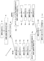
図1は、本発明の一実施例による、ブレードを製造するプロセスのフローチャートである。ブレードを製造するプロセス10では、ステップ20で、複数のブレードが生産される帯鋼のブレード素材が提供される。一実施例では、例えば、鋼帯はコイルの形態で提供され、よりコンパクトにして取扱いが容易になるようになっている。本発明の一実施例では、鋼材は、例えば等級C1095の鋼などの高炭素鋼、又は低合金鋼(例えば、AISI 4147)であるが、他の種類の材料を本発明の他の実施例で使用することができることが想到される。コイル状の鋼帯の長さは1km以上であることができる。鋼帯はまた、端部同士が溶接された複数コイルの形状で提供できる。鋼帯の寸法は、ブレードの所望の寸法に従って選択することができる。例えば、鋼帯は、19mmの幅及び0.6mmの厚さを有することができる。ただし、鋼帯は、鋼帯から形成されるブレードの意図される用途に応じて、他の寸法を有することができる。本発明の一実施例では、鋼帯は、約300HVの最高硬さを有する。
FIG. 1 is a flowchart of a process for manufacturing a blade, according to one embodiment of the present invention. In a
ステップ30で、鋼帯材料はポンチ・プレスに送られ、そこで、ブレードをカートリッジ内に、又は万能ナイフのブレード・キャリア上に固定するために用いられる付着点を設けるため、鋼帯に複数の開口部が打ち抜かれる。それに加えて、商標名、ロゴ、又は他のしるしも打ち抜くことができる。次に、ステップ40で、鋼帯はスコアリング加工され、軸線方向に間隔を空けた複数のスコアリング線(刻み線)を形成する。各スコアリング線は、各ブレードの側縁部にそれぞれ対応し、スコアリングされた鋼帯を後で複数のブレードへと折る又は切断するための分離線になる。図2は、スコアリング線210を有する鋼帯200の一部分の概略図である。スコアリング線は、台形を有する個々のブレード205を規定する。適切なスコアリングの形状を選択することで、平行四辺形のブレード、フック・ブレードなど、他の形態及び形状も得ることができる。
At
一実施例では、ステップ30及びステップ40のスコアリング及び穿孔工程を組み合わせて、単一の打抜き工程とすることができる。
In one embodiment, the scoring and drilling processes of
鋼帯をスコアリングおよび穿孔した後、ブレードを製造するための様々な選択肢を実行することができる。例えば、1つの選択肢(「選択肢1」)は、硬質材料(例えば、炭化タングステン)を被着させる前に鋼帯を硬化することを含み、図1のステップ50a〜90aによって表される。別の選択肢(「選択肢2」)は、鋼帯を硬化する前に硬質材料(例えば、炭化タングステン)を被着させることを含み、ステップ50b〜90bによって表される。選択肢1及び選択肢2を以下により詳細に記載する。 After scoring and drilling the steel strip, various options for manufacturing the blade can be implemented. For example, one option (“Option 1”) includes hardening the steel strip before applying a hard material (eg, tungsten carbide) and is represented by steps 50a-90a in FIG. Another option ("Option 2") involves depositing a hard material (e.g., tungsten carbide) prior to hardening the steel strip and is represented by steps 50b-90b. Option 1 and option 2 are described in more detail below.
選択肢1
プレスされたブレード素材の鋼帯のコイルは、次に、ステップ50aで、鋼帯材を硬化するため、熱処理ラインを通される。このプロセスでは、鋼はコイルから巻き出され、遷移温度を上回る温度まで鋼を加熱する硬化炉に通される。遷移温度は、鋼の組織が、室温で安定な体心立方構造から、高温即ち遷移温度を上回る温度で安定なオーステナイト(オーステナイト組織)として知られる面心立方構造へ変化する温度である。遷移温度は使用される鋼材に応じて変わる。本発明の一実施例では、鋼帯を硬化するための加熱は約800℃〜900℃の温度で行われる。例えば、等級C1095の鋼の場合、遷移温度は約820℃(約1508F)である。この実例では、鋼帯を硬化するための加熱は約820℃を上回る温度で行われる。
Option 1
The coil of pressed steel strip is then passed through a heat treatment line in step 50a to harden the strip. In this process, the steel is unwound from a coil and passed through a hardening furnace that heats the steel to a temperature above the transition temperature. The transition temperature is the temperature at which the steel structure changes from a body-centered cubic structure, which is stable at room temperature, to a face-centered cubic structure known as austenite (austenite structure), which is stable at high temperatures, ie, temperatures above the transition temperature. The transition temperature varies depending on the steel used. In one embodiment of the invention, the heating to harden the steel strip is performed at a temperature of about 800 ° C to 900 ° C. For example, for grade C1095 steel, the transition temperature is about 820 ° C. (about 1508 F). In this example, heating to harden the steel strip occurs at a temperature above about 820 ° C.
本発明の実施例では、硬化/加熱炉の長さは約8メートル(約26フィート)である。鋼帯は、分速約5〜7メートル(分速約16〜22フィート)の速度で移動する。鋼帯の酸化及び変色を防ぐため、例えば、窒素及び水素を本質的に含有する「アンモニア分解ガス」の制御された雰囲気が炉内に供給される。酸化及び変色を防ぐためにアンモニア分解ガスが使用できるが、「洗浄吸熱型ガス(scrubber endothermic gas)」又は「分子ふるいにかけた発熱型ガス(molecular sieved exothermic gas)」など他のガスが使用できるがそれらに限定されない。 In an embodiment of the invention, the length of the curing / heating furnace is about 8 meters (about 26 feet). The steel strip moves at a speed of about 5-7 meters per minute (about 16-22 feet per minute). In order to prevent oxidation and discoloration of the steel strip, for example, a controlled atmosphere of “ammonia decomposition gas” essentially containing nitrogen and hydrogen is fed into the furnace. Ammonia decomposition gas can be used to prevent oxidation and discoloration, but other gases such as “scrubber endothermic gas” or “molecular sieved exothermic gas” can be used. It is not limited to.
本発明の一実施例では、鋼帯を硬化するための鋼帯の加熱は、約75〜105秒間行われる。 In one embodiment of the invention, the heating of the steel strip to harden the steel strip is performed for about 75 to 105 seconds.
加熱(硬化)炉を出た後、ステップ60aで、熱硬化された鋼帯は急冷される。本発明の一実施例では、鋼帯を急冷するため、硬化された鋼帯は、鋼帯の上下に配置された液冷された伝導ブロックの間を通される。本発明の一実施例では、鋼を急冷するため、熱硬化された鋼帯は、カーバイドの摩耗帯材が鋼帯と接触している状態で、水冷された真鍮ブロックを通される。真鍮ブロックは、鋼帯を、臨界冷却速度を上回る速度で、例えば硬化温度(約820℃)から周囲温度(約25℃)まで冷却する。臨界冷却速度は、オーステナイト組織がマルテンサイト組織に変態することを確保するために鋼が冷却される速度である。マルテンサイト組織は体心正方構造である。マルテンサイト組織では、鋼は大きな内部応力を受ける。この内部応力は、鋼の焼き入れとして知られる現象の原因である。硬化の後、元は約300HV未満(熱処理前)であった鋼の硬さは、約850HV(約63HRC)になる。本発明の一実施例では、鋼帯の急冷は約2〜4秒間行われる。本発明の別の実施例では、鋼帯を急冷するのに気体又は液体が使用される。
After exiting the heating (hardening) furnace, in
次に、ステップ70aで、硬化された鋼帯は、鋼を150℃〜400℃の温度まで加熱する焼戻し炉を通り抜ける。このプロセスは、ブレードの靱性を改善し、選択された焼戻し温度に応じてブレードの硬さをHRc62〜55にする。 Next, in step 70a, the hardened steel strip passes through a tempering furnace that heats the steel to a temperature between 150 ° C and 400 ° C. This process improves the toughness of the blade and brings the blade hardness to HRc 62-55 depending on the tempering temperature selected.
本発明の一実施例では、焼戻し炉の長さは約8メートル(約26フィート)である。鋼帯は、分速約5〜7メートル(分速約16〜22フィート)の速度で移動する。鋼帯の酸化及び変色を防ぐため、例えば、窒素及び水素を本質的に含有する「アンモニア分解ガス」の制御雰囲気が炉内に供給される。酸化及び変色を防ぐためにアンモニア分解ガスが使用できるが、「洗浄吸熱型ガス(scrubber endothermic gas)」又は「分子ふるいにかけた発熱型ガス(molecular sieved exothermic gas)」など他のガスが使用できるがそれらに限定されない。本発明の一実施例では、鋼帯を焼き戻すための加熱は、約75〜105秒間行われる。 In one embodiment of the present invention, the length of the tempering furnace is about 8 meters (about 26 feet). The steel strip moves at a speed of about 5-7 meters per minute (about 16-22 feet per minute). In order to prevent oxidation and discoloration of the steel strip, for example, a controlled atmosphere of “ammonia decomposition gas” essentially containing nitrogen and hydrogen is fed into the furnace. Ammonia decomposition gas can be used to prevent oxidation and discoloration, but other gases such as “scrubber endothermic gas” or “molecular sieved exothermic gas” can be used. It is not limited to. In one embodiment of the invention, heating to temper the steel strip is performed for about 75 to 105 seconds.
加熱(焼戻し)炉を出た後、ステップ80aで、硬化され焼き戻された鋼帯は急冷される。本発明の一実施例では、硬化され焼き戻された鋼帯は、鋼帯を急冷するため、鋼帯の上下に配置された液冷された伝導性の急冷ブロックの間を通される。本発明の一実施例では、鋼を急冷するため、熱硬化され焼き戻された鋼帯は、カーバイドの摩耗帯材が鋼帯と接触している状態で、水冷された真鍮ブロックを通される。真鍮ブロックは、鋼表面の酸化を防ぐため、鋼帯を、臨界冷却速度を上回る速度で、例えば焼戻し温度(約150℃〜400℃)から周囲温度(約25℃)まで冷却する。 After exiting the heating (tempering) furnace, in step 80a, the hardened and tempered steel strip is quenched. In one embodiment of the invention, the hardened and tempered steel strip is passed between liquid-cooled conductive quench blocks located above and below the steel strip to quench the steel strip. In one embodiment of the present invention, the steel strip that has been heat-hardened and tempered is passed through a water-cooled brass block with the carbide wear strip in contact with the steel strip to quench the steel. . The brass block cools the steel strip at a rate above the critical cooling rate, for example from tempering temperature (about 150 ° C. to 400 ° C.) to ambient temperature (about 25 ° C.) to prevent oxidation of the steel surface.
次に、急冷された鋼帯のコイルは、ステップ90aで、硬質材料(例えば、炭化タングステン)の被覆を鋼帯の縁部に付与するように構成された、硬質材料(例えば、炭化タングステン)被着ステーションに連続的に供給される。硬質材料は、鋼帯よりも著しく大きな硬さを有する。本発明の一実施例では、硬質材料の硬さは少なくとも60Rcである。本発明の一実施例では、硬質材料の硬さは約70〜80Rcの範囲である。
Next, the quenched steel strip coil is coated in
次に、より詳しくは図3を参照すると、この図面は、本発明の一実施例による全体が300で示される被着ステーションの概略図であり、硬質材料、例えば炭化タングステンの被覆を移動している鋼帯200の縁部201に被着させる。被着ステーション300は、放射線ビーム355を鋼帯200に供給するように構成された放射線源305を含む。被着ステーション300は、放射線ビーム355を鋼帯200の目標部分に投射し集束させるように構成された投射系325を更に含む。
Referring now in more detail to FIG. 3, which is a schematic view of a deposition station, generally designated 300, according to one embodiment of the present invention, moving a coating of hard material, such as tungsten carbide. It is made to adhere to the
選択肢2
別の実施例では、鋼帯が硬化され焼き戻される前に、硬質材料(例えば、炭化タングステン/結合剤)粉末の被着(ステップ50b)が行われる。硬化及び焼戻し工程は、ステップ60b〜90bに示され、ステップ50a〜80aの工程にほぼ類似している。具体的には、硬質材料(例えば、炭化タングステン)を被着させた後、鋼帯は、ステップ60bで硬化され、ステップ70bで急冷される。次に、鋼帯は、ステップ80bで焼き戻され、ステップ90bで急冷される。
Option 2
In another embodiment, a hard material (eg, tungsten carbide / binder) powder is applied (step 50b) before the steel strip is hardened and tempered. The curing and tempering process is shown in
図3を再び参照すると、放射線源305は、鋼帯200を融解するのに十分な出力及びエネルギーを有する放射線ビームを出力するように構成される。一実施例では、放射線源は、波長が数マイクロメートルの赤外(IR)範囲の放射線ビームを出力するレーザーである。使用できるIRレーザーの一例は、主波長帯が約9.4〜10.6マイクロメートル付近を中心とするCO2レーザーである。CO2レーザーの出力は、約数キロワットの範囲、例えば1〜8キロワットであってもよい。一実施例では、CO2レーザーの出力は約6キロワットである。或いは、本発明の別の実施例では、例えば波長が400nm未満のUVレーザーなどの紫外(UV)範囲で動作するレーザーも使用できる。UVレーザーの例としてはエキシマー・レーザーが挙げられる。
Referring back to FIG. 3, the
放射線源305は光源に限定されないことが理解されるであろう。例えば、本発明の一実施例では、電子ビーム源も被着ステーション300に使用できる。この実現例では、電子ビーム源は、鋼帯200を融解するのに十分なエネルギー及び出力を有する電子ビームを供給するように構成される。
It will be appreciated that the
放射線源305によって出力される放射線ビーム355は、移動している鋼帯200の縁部にビームを集束させるように構成された投射系325に向けられる。鋼帯200の縁部201に集中された投射ビーム355のエネルギーは、鋼帯の目標部分と、供給粉末342中の結合剤(使用される場合)とを融解するために使用される。投射系325は、放射の方向付け、形付け、或いは制御を行うために、屈折型、反射型、磁気型、電磁型、静電型、若しくは他のタイプの光学部品、又はそれらの任意の組み合わせなど、様々なタイプの光学部品を含むことができる。放射線源が電子ビーム源である場合、ビーム355を制御し集束するために電磁レンズが使用できる。
The
投射系325は放射線源305と一体にできることが理解されるであろう。投射系325は、好ましくは固定フレームに取り付けられるが、投射された放射線ビーム355の形状を制御するために、投射系325の1つ又は複数の光学素子が移動可能であってもよいことが想到される。
It will be appreciated that the
放射線源305と鋼帯200との間に配置されたディスペンサー、即ち被着ヘッド320は、硬質材料(例えば、炭化タングステン)と結合剤元素との混合物342を鋼帯200の薄い縁部201に供給するように構成される。ディスペンサー320は、放射線ビーム355が通り抜けることができるように、全体として中空の形状を有する。
A dispenser, or
図4は、本発明の一実施例によるディスペンサー320の平面図を示す。ディスペンサー320は全体として円錐形の環状形状を有するが、他の形状(例えば、正方形、長方形、楕円形、多角形)を使用して混合物342を供給できることが想到される。ディスペンサー320は、粉末342、不活性の遮蔽ガス361、及びレーザー・ビームを単一の焦点Fに送るように設計された、一連の円錐形の環状キャビティを含む。本発明の一実施例では、遮蔽ガス361はアルゴンである。図4に示されるように、ディスペンサー320は、外側の円錐370と、不活性の遮蔽ガス361を供給するガス入口371とを含む。ディスペンサー370は、内側の円錐373と、混合物342を供給する入口374a〜bとを更に含む。中央の円錐375により、投射された放射線ビーム355を通過させるディスペンサー320内の通路が画定される。内側の円錐373は、中央の円錐375と外側の円錐370との間に配置され、チャネル376を画定する。内側の円錐373及び外側の円錐370は、それらの間に、不活性の遮蔽ガス361を流すためのチャネル377を画定する。他の配置も想到されることが理解されるであろう。また、混合物342を鋼帯200に供給するため、追加のチャネル又はより少数のチャネルが使用されてもよいことが理解されるであろう。
FIG. 4 shows a top view of a
中央の円錐375の周囲362の直径は、ディスペンサー320を鋼帯200から離す距離DI、及びチャネル376の長さに従って、混合物342の粒子が重力の作用を受けて鋼帯200の所定の部分に落ちるように選択される。そのような所定の部分は、一般に、鋼帯200に対する放射線ビーム355の焦点Fである。内周362の直径も、放射線ビーム355がディスペンサー320を通り抜けられるように選択される。
The diameter of the
内側の遮蔽ガス361は、図3に示されるように、焦点F付近の位置で混合物342の周りに遮蔽346を形成するように構成される。遮蔽346は、鋼帯200の酸化を防ぐため、硬質材料(例えば、炭化タングステン)の混合物342を被着する間、保護雰囲気となる。被着ステーション300を使用する間、内側の遮蔽ガス361は、鋼帯200の融解部分の周りの環境が酸化していないような形で、入口371からチャネル377を下って鋼帯まで流される。
The inner shielding gas 361 is configured to form a shielding 346 around the
ディスペンサー320は、被着ステーション300のフレーム(図示なし)に固定して取り付けられ、定置されるか、或いは少なくとも3つの方向、例えば、x、y、及びz方向に移動可能のどちらかにできる。移動可能なディスペンサー320を有することの利点は、鋼帯200に対するディスペンサー320の位置を正確に制御できることである。電気、電磁、及び/又は圧電性のアクチュエータなど、様々なモータ並びにアクチュエータを使用して、ディスペンサー320を変位させることができる。
The
ディスペンサー320に対する混合物342の供給は、複数の入口374a〜bによって行われる。一実現例では、混合物342の粒子を保管するために、容器(図示なし)が使用される。容器は、1つ又は複数の導管347を通じて複数の入口374a〜bと連通するように配置されるので、混合物は、重力の作用を受けてチャネル376を通じて鋼帯200の所定部まで運搬される。本発明の一実施例では、混合物342の供給は、例えば圧縮ガス又は機械的推進機器を用いて機械的に支援されることが想到される。
Supply of the
本発明の他の実施例では、ディスペンサー320の代替の配置を使用できることが理解されるであろう。例えば、環状のディスペンサーを使用する代わりに、鋼帯200の薄い縁部201に粒子を供給するため、1つ又は複数の個々のノズル若しくは被着ヘッドが使用できる。この構成は図5に示される。図5に示されるように、単一の電源505が、個々の被着ヘッド又はディスペンサー510a〜fと共に使用できる。個々の被着ヘッド510a〜fはそれぞれ、図3〜図4に示される被着ヘッド320に類似していてもよい。電源505によって供給される放射線ビーム(例えば、レーザー・ビーム)は、個々の被着ヘッド510a〜fに向けられるので、各被着ヘッドは、それ自体の放射線ビーム511a〜fを鋼帯200の薄い縁部201に供給する。出力は、各被着ヘッドについて個別に制御される。更に、被着ヘッドはそれぞれ、それ自体の混合物512a〜fを個別に供給するように構成される。図5の実施例では、電源は6個までのレーザー被着ヘッドを独立してサポートする。追加の又はより少数の被着ヘッドを本発明の一実施例において使用できることが理解されるであろう。この構成は非常に有益である。実際に、被着ヘッドそれぞれに対する出力を独立して制御することによって、被着層の形状をより良好に制御し、被着縁部それぞれにおいて異なる組成物(例えば、材料の異なる混合物、又は同じ混合物の異なる組成物)を被着させることが可能である。そのようにして、鋼帯200をコイル状にし、再度被覆することなく、単一の被覆工程で複数の被着を有することが可能である。動作の際、鋼帯200はx方向に沿って移動するので、異なる被着ヘッド20a〜fによって薄い縁部201に様々な層を被覆することができる。
It will be appreciated that alternative arrangements of the
図5に示されるように、個々のヘッド510a〜fは、鋼帯200の薄い縁部201の縁部に沿って位置付けられる。ただし、代替の配置が可能である。例えば、個々の被着ヘッドは、放射線ビームが集束される(地点F)鋼帯200の所定部分の周りに配置できる。更に、1つ又は複数の個々の被着ヘッドが、被着ヘッド又はディスペンサー320と類似した形で、定置或いは鋼帯200に対して移動可能にでき、また、粒子を鋼帯200まで運搬するために圧縮空気が使用できる。
As shown in FIG. 5, the individual heads 510 a-f are positioned along the edge of the
ディスペンサー320はまた、被着プロセスの完了後に混合物342の粒子がノズル360から出ることを防ぐため、1つ又は複数のシャッター(図示なし)を含むことができる。シャッターは、ディスペンサー320の内周に、又はチャネル内に、又はディスペンサーの上側部分に配置できる。
The
図3を再び参照すると、鋼帯200は、アクチュエータ335を使って、放射線ビーム355に対して少なくとも3つの方向、x、y、及びzに移動できる。図面に示されるように、移動可能な鋼帯200は、2つのローラー344a〜bを使用して、x方向に沿って放射線ビーム355を受けて移動される。2つのローラー344a〜bはアクチュエータ335を用いて位置付けることができる。1つ又は複数の別個のモータを使用して、鋼帯200を少なくとも3つの方向、x、y、及びzに移動させることができる。本発明の一実施例で使用できるアクチュエータの例としては、電気式及び電磁式のアクチュエータが挙げられる。鋼帯200の位置は、専用の電子部品及びサーボ制御システムによって制御できる。そのために、放射線ビーム355を受けて移動している鋼帯200の位置を測定するために、測定システム(図示なし)を使用できる。
Referring again to FIG. 3, the
硬質材料(例えば、炭化タングステン)及び結合剤元素の混合物342の被着は、保護されていない環境で実施できることが理解されるであろう。この実現例では、鋼帯200の酸化は、混合物342が被着されるブレード上で生じる。したがって、被着プロセスを完了した後に、酸化物を機械的又は化学的に除去することができる。例えば、混合物342を鋼帯200に被着させた後に、ワイヤ・ブラシ仕上げを使用するインライン研磨プロセスが適用されることが想到される。
It will be appreciated that the deposition of the hard material (eg, tungsten carbide) and
インライン測定システム350は、ブレード工程10で被着された混合物342の特性を制御するために使用できる。測定システム350が、フィルム混合物342の品質/組成及び厚さを制御する楕円偏光計などの非破壊光学系であることが好ましい。インライン測定システム350は、エミッター351a及び検出器351bを含むことができる。エミッター351aは、鋼帯200の部分を放射線ビームで照明するように構成される。放射線ビームは鋼帯200によって反射され、次に検出器351bによって検出される。続いて、反射された放射線ビームは、混合物342の被覆の特性を測定するために、専用の計測器で分析される。測定は、被着プロセスを完了した後、インライン測定システム350によって行われることが好ましい。鋼帯200の測定された特性が規格内にない場合、完成品のブレードを不合格にすべきであることを示すため、鋼帯の部分にマーカーで印を付けることができる。
The inline measurement system 350 can be used to control the properties of the
図3に示されるように、被着プロセスを制御するため、コントローラ345が使用される。コントローラ345は、ディスペンサー320、放射線源305、及びアクチュエータ335に動作可能に接続できる。コントローラ345は、照射設定を入力し、ディスペンサー320内の混合物342の粒子の量及び流れ、並びに/又は被着プロセスの間の鋼帯200の所望の位置付けを制御するため、操作者が操作できる。複数の被着ヘッド又はノズルが使用される構成では、操作者は、各被着ヘッドにおける所望の組成をコントローラ345に入力することができる。放射線ビーム355下における鋼帯200の薄い縁部201の位置付け、混合物342の粒子量、及び放射線源305の照射設定は、鋼帯200の幾何学形状及び性質に応じて大幅に変えることができることが理解されるであろう。
As shown in FIG. 3, a controller 345 is used to control the deposition process. Controller 345 can be operatively connected to
作動中は、鋼帯200の薄い縁部201は放射線ビーム355下で連続的に移動される。次に図6を参照すると、この図面は、被着プロセス中の鋼帯200の図を概略的に示す。x方向は、被着中の鋼帯200の移動方向を表す。図6に示されるように、鋼帯200の薄い縁部201を照射することによって、放射線ビーム355の焦点Fにおいて溶融池365が作られる。混合物342の粒子367は、ディスペンサー320によって放出され、重力の作用を受けて溶融池内に自由落下する。粒子367は、鋼帯200上に落下しながら、放射線ビーム355によって照射され融解される。その結果、ほぼ全ての粒子367は、溶融池365に達するときに既に融解している。
In operation, the
結合剤元素は、硬質材料(例えば、炭化タングステン)を溶融池の融解材料に結合させるように選択される。粒子367と鋼帯200との結合は全て、溶融池内の硬質材料(例えば、炭化タングステン)/結合剤元素の凝固によって達成される。これによって、硬質材料(例えば、炭化タングステン)/結合剤の空隙を含まない被着体が鋼帯200上に形成される。本発明の一実施例で使用できる結合剤の一例としては、コバルトが挙げられる。しかし、これは限定的なものではない。本発明の他の実施例では、追加の結合剤を使用できることが想到される。
The binder element is selected to bond a hard material (eg, tungsten carbide) to the molten material of the molten pool. Bonding between the
被着物の厚さは、粒子の供給速度、粒径、放射線源の照射設定(例えば、放射パルスのエネルギー、出力、周波数)、及び集束された放射線ビーム355の下を鋼帯200が通過する速度によって制御される。これらのパラメータは、コントローラ345によって入力され制御される。被着物の厚さは測定装置351によって測定される。
The thickness of the deposit depends on the particle feed rate, particle size, radiation source illumination settings (eg, radiation pulse energy, power, frequency), and the speed at which the
鋼帯200の変位速度は、被着物の厚さが常に規格内に留まっているように制御される。鋼帯200の速度は、放射線ビームの特性(例えば、パルスの波長及び周波数、エネルギー及び出力)、焦点のサイズ、並びに鋼帯200を構成する材料に応じて変えることができる。
The displacement speed of the
次に図7を参照すると、この図面は、単一のヘッド又はノズルを使用して混合物342を被着させた後の鋼帯200の概略図を示す。この図で分かるように、混合物342の単層202が鋼帯200の薄い縁部201に被覆される。図8は、複数のヘッド又はノズルを使用して異なる混合物を被着させた後の鋼帯200の概略図を示す。この実施例では、2つのヘッドが使用され、各ヘッドは異なる混合物組成を供給するように構成される。図8に示されるように、2つの層203a〜bが鋼帯200の薄い縁部201に被覆される。同じ又は異なる混合物組成を有する2つを超える層を、薄い縁部201に被覆できることが理解されるであろう。更に、層はそれぞれ、異なる被着ヘッド又はノズルにより被覆できる。
Reference is now made to FIG. 7, which shows a schematic view of the
硬質材料(例えば、炭化タングステン)の被着は、ブレード母材の反対側に同じ方法で行うことができることが理解されるであろう。 It will be appreciated that the deposition of a hard material (eg tungsten carbide) can be done in the same way on the opposite side of the blade matrix.
図1を再び参照すると、被着ステーション300を出た後、鋼帯200は研削機に送られる。一実施例では、ステップ100で、鋼帯は再びコイル状にされ、鋼帯の縁部を研削するため、研削機に送られる。鋼帯の縁部が10〜32°などの比較的浅い角度に研削される。この角度は、ブレードの両側に研削されるので、ブレードは、図9から理解できるように、縁部を二分するブレードの長手方向軸線に対してほぼ対称になる。それに加えて、やはり図9から理解できるように、研削角は長手方向軸線に対して測定される。ブレードを切断すべき材料に押し通すために必要な力を低減させるため、角度は浅くなるように選択される。図9は、本発明の一実施例による鋼帯の研削縁部の一例の断面図である。この例では、鋼帯200の研削縁部371の角度は22°±2°である。
Referring again to FIG. 1, after leaving the
鋼帯200は、選択肢1に従ってステップ90で硬質合金被覆を被着させた後、更に熱処理できることが理解されるであろう。例えば、一実現例では、ステップ50a、60a、70a、及び80aで記載したのと類似の態様で、鋼帯200を再び硬化し、急冷し、焼き戻すことができる。
It will be appreciated that the
研削の後、ステップ100で、鋼帯の縁部はホーニング仕上げできる。ホーニング仕上げのプロセスによって、26°〜36°などの第2のより鈍い角が研削縁部の頂部に作られる。このより深いホーニング角度によって、より浅い研削角度よりも強い縁部が得られ、切刃の寿命を延長することが可能になる。その結果、鋼帯は、二重の角度の縁部を有する。 After grinding, at step 100, the edge of the steel strip can be honed. The honing process creates a second blunt angle, such as 26 ° -36 °, at the top of the grinding edge. This deeper honing angle results in a stronger edge than the shallower grinding angle, and can extend the life of the cutting edge. As a result, the steel strip has a double angled edge.
最後に、加工済みの鋼帯は、ステップ90で、スコアリング線に沿って鋼帯を破断して複数のブレードを生産するため、それぞれのスコアリング線のところで鋼帯の長さに沿って折られる。本発明の製造プロセスにより得られたブレードの一実施例の一例は、図9にその様々な寸法で示される。 Finally, the processed steel strip is folded along the length of the steel strip at each scoring line in step 90 to break the steel strip along the scoring line to produce multiple blades. It is done. An example of one embodiment of a blade obtained by the manufacturing process of the present invention is shown in its various dimensions in FIG.
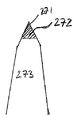
図9は、鋼帯200を研削し刃付けした後のブレード205の断面図を示す。ブレード205は、主に硬質材料(例えば、炭化タングステン)272により作られた切削端271を含むと共に、ブレードの残りの部分は、図9に273で示される、ブレード205を構成するコア材料で作られる。当業者には理解されるように、本発明の一実施例に従って炭化タングステンを被着させることによって、ブレードの残りの表面と同一面内にある炭化タングステンの表面を有するブレードが得られる。図9で分かるように、炭化タングステンは、炭化タングステンとブレードのコア材料273との間に継ぎ目のない遷移が形成されるようにブレードに溶接される。
FIG. 9 shows a cross-sectional view of the
本発明の原理を上述の例示的実施例において明らかにしてきたが、本発明を実施する際に使用される構造、配置、比率、部材、材料、及び構成要素を様々に変更できることが当業者には明白となるであろう。 Although the principles of the present invention have been clarified in the exemplary embodiments described above, it will be apparent to those skilled in the art that the structure, arrangement, ratio, members, materials, and components used in practicing the present invention can be varied. Will be clear.
したがって、本発明の目的が十分且つ効率的に達成されていることが分かるであろう。ただし、上述の好ましい特定の実施例は、本発明の機能上及び構造上の原理を説明する目的で示され、記載されているものであり、そうした原理から逸脱することなく変わり得ることが理解されるであろう。したがって、本発明は、以下の請求項の趣旨及び範囲内に包含される全ての変更を含む。 Thus, it will be appreciated that the objectives of the present invention have been fully and efficiently achieved. It will be understood, however, that the specific preferred embodiments described above are shown and described for the purpose of illustrating the functional and structural principles of the invention and may be varied without departing from such principles. It will be. Accordingly, this invention includes all modifications encompassed within the spirit and scope of the following claims.
Claims (21)
硬質材料により被覆された鋼帯を形成するために、前記硬質材料を含む混合物を移動可能な鋼帯の縁部に被着させる工程と、
前記硬質材料により被覆された鋼帯の前記縁部を研削する工程と、
前記研削する工程に続いて、前記硬質材料により被覆された鋼帯から個々のブレードを形成する工程と
を含み、
前記方法が、前記被着させる工程の前に、前記移動可能な鋼帯を加熱および急冷することにより前記移動可能な鋼帯を硬化させる工程を含み、
加熱による前記移動可能な鋼帯の硬化は、前記被着させる工程の前のみに行われることを特徴とする、ブレードを製造する方法。 A method of manufacturing a blade of a cutting tool, the method comprising:
Depositing a mixture containing the hard material on the edge of a movable steel strip to form a steel strip coated with a hard material;
Grinding the edge of the steel strip coated with the hard material;
The Following grinding to process, look including the step of forming the hard material from the coated steel strip by the individual blades,
The method includes the step of hardening the movable steel strip by heating and quenching the movable steel strip prior to the depositing step;
A method of manufacturing a blade, characterized in that hardening of the movable steel strip by heating is performed only before the step of depositing .
前記個々のブレードを画定する間隔を空けた複数のスコアリング線を形成するために、前記移動可能な鋼帯をスコアリングする工程
を更に含む、請求項1に記載されたブレードを製造する方法。 Before the depositing step,
To form a plurality of scoring lines spaced defining the individual blades, as engineering scoring the movable steel strip
The method of manufacturing a blade according to claim 1 , further comprising:
前記鋼帯の一部分を融解させるために、前記移動可能な鋼帯を放射線ビームで照射する工程と、
前記硬質材料及び結合剤元素を含む前記混合物を前記鋼帯の融解部分に供給する工程と
を含む、請求項1に記載されたブレードを製造する方法。 The step of depositing comprises
Irradiating the movable steel strip with a radiation beam to melt a portion of the steel strip;
Feeding the mixture containing the hard material and binder element to a molten portion of the steel strip.
前記鋼帯の一部分を融解するために、前記移動可能な鋼帯を複数の放射線ビームで照射する工程と、
複数の被覆材料層を形成するように、複数の硬質材料及び結合剤元素の混合物を前記鋼帯の前記融解部分に供給する工程とを含む、請求項1に記載されたブレードを製造する方法。 The step of depositing comprises
Irradiating the movable steel strip with a plurality of radiation beams to melt a portion of the steel strip;
Supplying a mixture of hard materials and binder elements to the melted portion of the steel strip to form a plurality of coating material layers.
Applications Claiming Priority (4)
| Application Number | Priority Date | Filing Date | Title |
|---|---|---|---|
| US7487508P | 2008-06-23 | 2008-06-23 | |
| US61/074,875 | 2008-06-28 | ||
| US12/486,529 US8505414B2 (en) | 2008-06-23 | 2009-06-17 | Method of manufacturing a blade |
| US12/486,529 | 2009-06-17 |
Publications (2)
| Publication Number | Publication Date |
|---|---|
| JP2010000596A JP2010000596A (en) | 2010-01-07 |
| JP5534720B2 true JP5534720B2 (en) | 2014-07-02 |
Family
ID=41198568
Family Applications (1)
| Application Number | Title | Priority Date | Filing Date |
|---|---|---|---|
| JP2009148697A Expired - Fee Related JP5534720B2 (en) | 2008-06-23 | 2009-06-23 | Blade manufacturing method |
Country Status (4)
| Country | Link |
|---|---|
| US (1) | US8505414B2 (en) |
| EP (1) | EP2138263B1 (en) |
| JP (1) | JP5534720B2 (en) |
| AU (1) | AU2009202494B2 (en) |
Families Citing this family (31)
| Publication number | Priority date | Publication date | Assignee | Title |
|---|---|---|---|---|
| US8505414B2 (en) * | 2008-06-23 | 2013-08-13 | Stanley Black & Decker, Inc. | Method of manufacturing a blade |
| US8769833B2 (en) | 2010-09-10 | 2014-07-08 | Stanley Black & Decker, Inc. | Utility knife blade |
| US20120144680A1 (en) | 2010-12-10 | 2012-06-14 | Stanley Black & Decker, Inc. | Cutting blade and method of manufacturing the same |
| US9902018B2 (en) * | 2012-05-25 | 2018-02-27 | European Space Agency | Multi-wire feeder method and system for alloy sample formation and additive manufacturing |
| GB201212629D0 (en) | 2012-07-16 | 2012-08-29 | Prec Engineering Technologies Ltd | A machine tool |
| WO2014063910A1 (en) * | 2012-10-24 | 2014-05-01 | Nv Bekaert Sa | A flat fixed abrasive sawing wire |
| US8884407B2 (en) * | 2012-12-04 | 2014-11-11 | Infineon Technologies Ag | Devices for providing an electrical connection |
| US9833785B2 (en) * | 2012-12-17 | 2017-12-05 | Kooima Company | Method of making a processor disk |
| EP2774714A1 (en) * | 2013-03-06 | 2014-09-10 | Siemens Aktiengesellschaft | Laser build-up welding with low energy input into the substrate |
| EP2875890A1 (en) * | 2013-11-25 | 2015-05-27 | Böhler-Uddeholm Precision Strip GmbH | Method for producing a precursor material for a cutting tool and corresponding precursor material |
| EP2875891A1 (en) * | 2013-11-25 | 2015-05-27 | Böhler-Uddeholm Precision Strip GmbH | Method for producing a precursor material for a cutting tool and corresponding precursor material |
| CN103707024B (en) * | 2013-12-25 | 2016-04-13 | 安徽日升机械制造有限公司 | A kind of preparation method of high accuracy longitudinal shearing slitting blade |
| CN103639676B (en) * | 2013-12-25 | 2016-02-10 | 安徽日升机械制造有限公司 | A kind of crescent-moon scissors slice processing method with high-wearing feature and strong impact resistance |
| JP6092467B2 (en) * | 2015-03-24 | 2017-03-08 | 技術研究組合次世代3D積層造形技術総合開発機構 | Processing nozzle, processing head, processing equipment |
| US10648051B2 (en) * | 2015-04-24 | 2020-05-12 | Kondex Corporation | Reciprocating cutting blade with cladding |
| GB2540385B (en) | 2015-07-15 | 2017-10-11 | C4 Carbides Ltd | Improvements in or relating to tool blades and their manufacture |
| GB2540476A (en) * | 2015-07-15 | 2017-01-18 | C4 Carbides Ltd | Improvements in or relating to tool blades and their manufacture |
| CN107486690B (en) * | 2015-08-14 | 2019-05-17 | 安徽省凌锋冶金机械有限公司 | A kind of manufacturing method of disc shear blade thereby |
| US10688596B2 (en) | 2015-12-18 | 2020-06-23 | Illinois Tool Works Inc. | Wire manufactured by additive manufacturing methods |
| JP6761596B2 (en) * | 2016-07-29 | 2020-09-30 | 三菱マテリアル株式会社 | Cutting tool made of composite material |
| JP7099800B2 (en) * | 2016-07-29 | 2022-07-12 | 三菱マテリアル株式会社 | Cutting tools consisting of composite members and future |
| US10321633B1 (en) * | 2016-11-10 | 2019-06-18 | Ronald J. Kile | Threshing bars with reinforced spikes and cutting blades |
| US10457035B2 (en) | 2017-03-07 | 2019-10-29 | General Electric Company | Apparatuses and systems for net shape manufacturing |
| CN107130239B (en) * | 2017-06-28 | 2019-12-31 | 苏州大学 | Method for laser cladding forming of metal or alloy under local atmosphere protection |
| US10994379B2 (en) * | 2019-01-04 | 2021-05-04 | George H. Lambert | Laser deposition process for a self sharpening knife cutting edge |
| JP7227826B2 (en) * | 2019-03-29 | 2023-02-22 | 株式会社フジクラ | Manufacturing method of blade body for optical fiber cutter |
| DE102019117796A1 (en) * | 2019-07-02 | 2021-01-07 | WIKUS-Sägenfabrik Wilhelm H. Kullmann GmbH & Co. KG | Cutting tool with buffer particles |
| CN111673193B (en) * | 2020-06-15 | 2021-04-23 | 浙江津灿工贸有限公司 | Sawtooth plane machining mechanism for electric saw |
| CN112123285B (en) * | 2020-09-09 | 2021-12-24 | 阳江市睿盈科技有限公司 | Welding cutter and manufacturing method thereof |
| US20220347876A1 (en) * | 2021-05-03 | 2022-11-03 | The Gillette Company Llc | Metals for razor blade applications |
| WO2023220770A1 (en) * | 2022-05-17 | 2023-11-23 | Commonwealth Scientific And Industrial Research Organisation | Process of forming a cutting tool with additively deposited cutting edge |
Family Cites Families (110)
| Publication number | Priority date | Publication date | Assignee | Title |
|---|---|---|---|---|
| US476531A (en) * | 1892-06-07 | Thomas a | ||
| US1639335A (en) | 1924-06-24 | 1927-08-16 | Autostrop Patents Corp | Blade holder |
| US1823976A (en) | 1927-03-11 | 1931-09-22 | Gillette Safety Razor Co | Safety razor |
| US1855478A (en) | 1927-03-12 | 1932-04-26 | Gillette Safety Razor Co | Safety razor |
| US1849919A (en) | 1929-02-11 | 1932-03-15 | Gillette Safety Razor Co | Safety razor |
| US1821578A (en) | 1929-04-25 | 1931-09-01 | Fedco System Inc | Process of making identification plates |
| US2073501A (en) | 1932-10-08 | 1937-03-09 | Gillette Safety Razor Co | Coloring and hardening steel |
| US2137817A (en) | 1934-03-30 | 1938-11-22 | Windsor Mfg Co | Process of coloring metal |
| US2032963A (en) | 1934-09-29 | 1936-03-03 | Rockwell W S Co | Method of coloring and hardening steel |
| US2244053A (en) | 1935-06-22 | 1941-06-03 | Gregory J Comstock | Hard cemented carbide composite |
| US2073502A (en) | 1936-04-08 | 1937-03-09 | Gillette Safety Razor Co | Safety razor blade and blade strip |
| US2131505A (en) | 1938-08-16 | 1938-09-27 | Henry M Garsson | Treating steel |
| US2326774A (en) | 1939-07-11 | 1943-08-17 | Benjamin H Freedman | Safety razor |
| US2964420A (en) | 1955-06-14 | 1960-12-13 | Union Carbide Corp | Refractory coated body |
| US3283117A (en) | 1965-04-22 | 1966-11-01 | Philip Morris Inc | Method for coating cutting edges of sharpened instruments |
| US3480483A (en) | 1965-05-06 | 1969-11-25 | Wilkinson Sword Ltd | Razor blades and methods of manufacture thereof |
| GB1147393A (en) | 1966-02-14 | 1969-04-02 | Wilkinson Sword Ltd | Improvements in or relating to the marking of metal surfaces by electrolytic action |
| GB1149781A (en) | 1966-06-09 | 1969-04-23 | Gillette Industries Ltd | Improvements in or relating to razor blades |
| US3490314A (en) | 1967-03-01 | 1970-01-20 | Gillette Co | Cutting instruments |
| US3496973A (en) | 1967-04-12 | 1970-02-24 | Robert L Ballard | Cutting tool edge construction |
| US3652342A (en) | 1967-06-07 | 1972-03-28 | Gillette Co | Razor blades and processes for the preparation thereof |
| US3754329A (en) | 1967-11-06 | 1973-08-28 | Warner Lambert Co | Razor blade with rf sputtered coating |
| US3664884A (en) | 1968-03-11 | 1972-05-23 | Concept Research Corp | Method of coloring metals by the application of heat |
| US3916523A (en) | 1969-09-29 | 1975-11-04 | Warner Lambert Co | Coated razor blade |
| BR7102060D0 (en) | 1970-04-17 | 1973-04-05 | Wilkinson Sword Ltd | SHAVING BLADE AND PROCESS FOR THE SAME MANUFACTURE |
| US3751283A (en) | 1971-03-08 | 1973-08-07 | Remington Arms Co Inc | Armored metal tools and production thereof |
| US4015100A (en) | 1974-01-07 | 1977-03-29 | Avco Everett Research Laboratory, Inc. | Surface modification |
| US3952180A (en) | 1974-12-04 | 1976-04-20 | Avco Everett Research Laboratory, Inc. | Cladding |
| US4004042A (en) | 1975-03-07 | 1977-01-18 | Sirius Corporation | Method for applying a wear and impact resistant coating |
| GB2052566B (en) | 1979-03-30 | 1982-12-15 | Rolls Royce | Laser aplication of hard surface alloy |
| US4323756A (en) | 1979-10-29 | 1982-04-06 | United Technologies Corporation | Method for fabricating articles by sequential layer deposition |
| US4299860A (en) | 1980-09-08 | 1981-11-10 | The United States Of America As Represented By The Secretary Of The Navy | Surface hardening by particle injection into laser melted surface |
| DE3202697A1 (en) | 1982-01-28 | 1983-08-04 | Kapp & Co Werkzeugmaschinenfabrik, 8630 Coburg | METHOD AND DEVICE FOR FINE-PROFILING TOOLS COATED WITH SUPER-HARD MATERIALS |
| JPS58177238A (en) * | 1982-04-05 | 1983-10-17 | Toshiba Corp | Manufacture of edged tool |
| DE3216456A1 (en) | 1982-05-03 | 1983-11-03 | Robert Bosch Gmbh, 7000 Stuttgart | METHOD FOR Embedding Hard Materials In The Surface Of Chip Removal Tools |
| SE437682B (en) | 1982-10-13 | 1985-03-11 | Inventing Ab | SET AND APPLICATION TO APPLY A NUTS-RESISTANT COATING ON A THIN METALLIC, BAND-SHAPED BEARING MATERIAL |
| US4547649A (en) | 1983-03-04 | 1985-10-15 | The Babcock & Wilcox Company | Method for superficial marking of zirconium and certain other metals |
| CA1265209A (en) | 1984-02-17 | 1990-01-30 | Robert Langen | Process to remove contaminants, particularly rust/from metallic surfaces |
| IT1179061B (en) | 1984-08-20 | 1987-09-16 | Fiat Auto Spa | PROCEDURE FOR CARRYING OUT A TREATMENT ON METAL PIECES WITH THE ADDITION OF A VALUE MATERIAL AND WITH THE USE OF A POWER LASER |
| US4653373A (en) | 1986-01-08 | 1987-03-31 | Gerber Scientific Inc. | Knife blade and method for making same |
| JPH0649228B2 (en) * | 1986-03-25 | 1994-06-29 | 大同特殊鋼株式会社 | Tool manufacturing method |
| US6083570A (en) | 1987-03-31 | 2000-07-04 | Lemelson; Jerome H. | Synthetic diamond coatings with intermediate amorphous metal bonding layers and methods of applying such coatings |
| US4724299A (en) | 1987-04-15 | 1988-02-09 | Quantum Laser Corporation | Laser spray nozzle and method |
| US5204167A (en) | 1989-02-23 | 1993-04-20 | Toshiba Tungaloy Co., Ltd. | Diamond-coated sintered body excellent in adhesion and process for preparing the same |
| US4981756A (en) | 1989-03-21 | 1991-01-01 | Vac-Tec Systems, Inc. | Method for coated surgical instruments and tools |
| US5066553A (en) | 1989-04-12 | 1991-11-19 | Mitsubishi Metal Corporation | Surface-coated tool member of tungsten carbide based cemented carbide |
| US5368947A (en) | 1991-08-12 | 1994-11-29 | The Penn State Research Foundation | Method of producing a slip-resistant substrate by depositing raised, bead-like configurations of a compatible material at select locations thereon, and a substrate including same |
| FR2685922B1 (en) | 1992-01-07 | 1995-03-24 | Strasbourg Elec | COAXIAL NOZZLE FOR SURFACE TREATMENT UNDER LASER IRRADIATION, WITH SUPPLY OF MATERIALS IN POWDER FORM. |
| US5295305B1 (en) | 1992-02-13 | 1996-08-13 | Gillette Co | Razor blade technology |
| US5304771A (en) | 1992-02-18 | 1994-04-19 | D. A. Griffin Corporation | Apparatus for precisely metering powder for welding |
| WO1993017141A1 (en) | 1992-02-20 | 1993-09-02 | The Dow Chemical Company | Rhenium-bound tungsten carbide composites |
| GB9208952D0 (en) | 1992-04-24 | 1992-06-10 | Mcphersons Ltd | Knife blades |
| US5453329A (en) | 1992-06-08 | 1995-09-26 | Quantum Laser Corporation | Method for laser cladding thermally insulated abrasive particles to a substrate, and clad substrate formed thereby |
| US5449536A (en) | 1992-12-18 | 1995-09-12 | United Technologies Corporation | Method for the application of coatings of oxide dispersion strengthened metals by laser powder injection |
| JPH06226554A (en) * | 1993-02-09 | 1994-08-16 | N T Kk | Manufacture of blade body |
| JPH06304820A (en) * | 1993-04-23 | 1994-11-01 | Matsushita Electric Works Ltd | Cutter and manufacture thereof |
| US5731046A (en) | 1994-01-18 | 1998-03-24 | Qqc, Inc. | Fabrication of diamond and diamond-like carbon coatings |
| US5620754A (en) | 1994-01-21 | 1997-04-15 | Qqc, Inc. | Method of treating and coating substrates |
| US5477026A (en) | 1994-01-27 | 1995-12-19 | Chromalloy Gas Turbine Corporation | Laser/powdered metal cladding nozzle |
| DE4437911A1 (en) | 1994-10-22 | 1996-04-25 | Zwilling J A Henckels Ag | Knife and method of making a knife |
| US5486676A (en) | 1994-11-14 | 1996-01-23 | General Electric Company | Coaxial single point powder feed nozzle |
| US5543183A (en) | 1995-02-17 | 1996-08-06 | General Atomics | Chromium surface treatment of nickel-based substrates |
| GB9506494D0 (en) | 1995-03-30 | 1995-05-17 | Mcphersons Ltd | Knife blades |
| US5722803A (en) | 1995-07-14 | 1998-03-03 | Kennametal Inc. | Cutting tool and method of making the cutting tool |
| US5728434A (en) | 1995-08-08 | 1998-03-17 | Pacific/Hoe Saw And Knife Company | Method of applying a wear-resistant coating on a thin, metallic strip-shaped carrier |
| US5837960A (en) | 1995-08-14 | 1998-11-17 | The Regents Of The University Of California | Laser production of articles from powders |
| US6316065B1 (en) | 1995-10-05 | 2001-11-13 | Ble Bayerisches Laserzentrum Gemeinnutzige Forschungsgesellschaft Mbh | Process and device for manufacturing a cutting tool |
| US5724868A (en) | 1996-01-11 | 1998-03-10 | Buck Knives, Inc. | Method of making knife with cutting performance |
| US6293020B1 (en) | 1997-02-14 | 2001-09-25 | Nitinol Technologies, Inc. | Cutting instruments |
| US5736709A (en) | 1996-08-12 | 1998-04-07 | Armco Inc. | Descaling metal with a laser having a very short pulse width and high average power |
| US5906053A (en) | 1997-03-14 | 1999-05-25 | Fisher Barton, Inc. | Rotary cutting blade having a laser hardened cutting edge and a method for making the same with a laser |
| CA2207579A1 (en) | 1997-05-28 | 1998-11-28 | Paul Caron | A sintered part with an abrasion-resistant surface and the process for producing it |
| US6146476A (en) | 1999-02-08 | 2000-11-14 | Alvord-Polk, Inc. | Laser-clad composite cutting tool and method |
| US6396025B1 (en) | 1999-07-01 | 2002-05-28 | Aeromet Corporation | Powder feed nozzle for laser welding |
| DE19931948B4 (en) | 1999-07-09 | 2004-11-11 | Zwilling J. A. Henckels Ag | Method of making a blade of a cutting tool and product made therewith |
| US6534745B1 (en) | 1999-09-27 | 2003-03-18 | Mathew T. J. Lowney | Nozzle particularly suited to direct metal deposition |
| US6756561B2 (en) | 1999-09-30 | 2004-06-29 | National Research Council Of Canada | Laser consolidation apparatus for manufacturing precise structures |
| JP4741056B2 (en) | 2000-06-05 | 2011-08-03 | 株式会社貝印刃物開発センター | Blade member and method of manufacturing the blade edge |
| US6497772B1 (en) | 2000-09-27 | 2002-12-24 | Molecular Metallurgy, Inc. | Surface treatment for improved hardness and corrosion resistance |
| US6805944B2 (en) | 2001-03-26 | 2004-10-19 | Mitsubishi Materials Corporation | Coated cemented carbide cutting tool |
| US7140113B2 (en) | 2001-04-17 | 2006-11-28 | Lazorblades, Inc. | Ceramic blade and production method therefor |
| AT411654B (en) * | 2001-06-25 | 2004-04-26 | Boehler Ybbstal Band Gmbh & Co | METHOD FOR PRODUCING A CUTTING TOOL |
| US7712222B2 (en) | 2001-07-26 | 2010-05-11 | Irwin Industrial Tool Company | Composite utility blade, and method of making such a blade |
| US6701627B2 (en) * | 2001-07-26 | 2004-03-09 | American Saw & Mfg. Company, Inc. | Composite utility knife blade |
| EP1340583A1 (en) | 2002-02-20 | 2003-09-03 | ALSTOM (Switzerland) Ltd | Method of controlled remelting of or laser metal forming on the surface of an article |
| US6617271B1 (en) | 2002-03-19 | 2003-09-09 | Vladimir Yurievich Kodash | Tungsten carbide cutting tool materials |
| US6857255B1 (en) | 2002-05-16 | 2005-02-22 | Fisher-Barton Llc | Reciprocating cutting blade having laser-hardened cutting edges and a method for making the same with a laser |
| WO2004020139A1 (en) | 2002-08-28 | 2004-03-11 | The P.O.M. Group | Part-geometry independant real time closed loop weld pool temperature control system for multi-layer dmd process |
| US7139633B2 (en) | 2002-08-29 | 2006-11-21 | Jyoti Mazumder | Method of fabricating composite tooling using closed-loop direct-metal deposition |
| EP1396556A1 (en) | 2002-09-06 | 2004-03-10 | ALSTOM (Switzerland) Ltd | Method for controlling the microstructure of a laser metal formed hard layer |
| JP4204293B2 (en) | 2002-09-30 | 2009-01-07 | アイシン軽金属株式会社 | Image forming method on aluminum alloy surface |
| US7111376B2 (en) | 2003-01-13 | 2006-09-26 | The Stanley Works | Tool with inserted blade members |
| EP1454705A1 (en) | 2003-03-05 | 2004-09-08 | Trumpf Werkzeugmaschinen GmbH + Co. KG | Thermal treatment of a workpiece made of metal, in particular aluminium |
| DE10320652A1 (en) | 2003-05-07 | 2004-12-02 | Kennametal Widia Gmbh & Co.Kg | Tool, especially a cutting tool, comprising a substrate member onto which at least one layer is deposited by means of chemical vapor deposition (CVD) used in machining operations, e.g. metal cutting |
| SE527180C2 (en) | 2003-08-12 | 2006-01-17 | Sandvik Intellectual Property | Rack or scraper blades with abrasion resistant layer and method of manufacture thereof |
| US6995334B1 (en) | 2003-08-25 | 2006-02-07 | Southern Methodist University | System and method for controlling the size of the molten pool in laser-based additive manufacturing |
| US20050056628A1 (en) | 2003-09-16 | 2005-03-17 | Yiping Hu | Coaxial nozzle design for laser cladding/welding process |
| JP4299157B2 (en) | 2004-02-03 | 2009-07-22 | トヨタ自動車株式会社 | Powder metal overlay nozzle |
| DE602005025611D1 (en) * | 2004-02-18 | 2011-02-10 | Tarrerias Bonjean Soc D Expl | METHOD FOR PRODUCING A CUTTING KNIFE |
| US7673541B2 (en) | 2004-06-03 | 2010-03-09 | The Gillette Company | Colored razor blades |
| US20060049153A1 (en) | 2004-09-08 | 2006-03-09 | Cahoon Christopher L | Dual feed laser welding system |
| US7259353B2 (en) | 2004-09-30 | 2007-08-21 | Honeywell International, Inc. | Compact coaxial nozzle for laser cladding |
| US7284461B2 (en) | 2004-12-16 | 2007-10-23 | The Gillette Company | Colored razor blades |
| US8322253B2 (en) * | 2005-07-08 | 2012-12-04 | Stanley Black & Decker, Inc. | Method of manufacturing a utility knife blade having an induction hardened cutting edge |
| US20070131060A1 (en) | 2005-12-14 | 2007-06-14 | The Gillette Company | Automated control of razor blade colorization |
| EP1857571B1 (en) | 2006-05-10 | 2011-03-09 | Fraunhofer-Gesellschaft zur Förderung der angewandten Forschung e.V. | A cutting implement |
| EP1953004B1 (en) | 2007-01-24 | 2012-03-07 | KUM Limited | Sharpener blade |
| US20080189957A1 (en) | 2007-02-12 | 2008-08-14 | The Stanley Works | Bi-metal chisel blade |
| US8505414B2 (en) * | 2008-06-23 | 2013-08-13 | Stanley Black & Decker, Inc. | Method of manufacturing a blade |
| US8592711B2 (en) | 2009-10-01 | 2013-11-26 | George H. Lambert | Apparatus and method of electronically impregnating a wear-resistant cutting edge |
-
2009
- 2009-06-17 US US12/486,529 patent/US8505414B2/en active Active
- 2009-06-22 EP EP09163418.8A patent/EP2138263B1/en active Active
- 2009-06-22 AU AU2009202494A patent/AU2009202494B2/en not_active Ceased
- 2009-06-23 JP JP2009148697A patent/JP5534720B2/en not_active Expired - Fee Related
Also Published As
| Publication number | Publication date |
|---|---|
| JP2010000596A (en) | 2010-01-07 |
| US20090314136A1 (en) | 2009-12-24 |
| EP2138263A3 (en) | 2010-02-17 |
| US8505414B2 (en) | 2013-08-13 |
| AU2009202494A1 (en) | 2010-01-14 |
| EP2138263B1 (en) | 2017-01-18 |
| AU2009202494B2 (en) | 2014-08-14 |
| EP2138263A2 (en) | 2009-12-30 |
Similar Documents
| Publication | Publication Date | Title |
|---|---|---|
| JP5534720B2 (en) | Blade manufacturing method | |
| US9393984B2 (en) | Utility knife blade | |
| US10828720B2 (en) | Foil-based additive manufacturing system and method | |
| US9764442B2 (en) | Cutting/polishing tool and manufacturing method thereof | |
| CN202480108U (en) | Cutter blade | |
| US7401537B1 (en) | Cutter insert gum modification method and apparatus | |
| CN108778610B (en) | Laser processing apparatus and laser processing method | |
| AU781334B2 (en) | Method for producing a surface-alloyed cylindrical, partially cylindrical or hollow cylindrical component and a device for carrying out said method | |
| US20220288688A1 (en) | Cladded tool and method of making a cladded tool | |
| WO2018089080A1 (en) | Foil-based additive manufacturing system and method | |
| EP3525972B1 (en) | Method of manufacturing a toothed blade and apparatus for manufacturing such a blade | |
| CN102094111A (en) | Bar hot shear blade laser-quenching manufacturing process | |
| WO1997004914A1 (en) | Pulsed laser cladding arrangement | |
| JP7531211B2 (en) | Method for repairing protrusions on turbine rotors | |
| WO2022190376A1 (en) | Mold component manufacturing method |
Legal Events
| Date | Code | Title | Description |
|---|---|---|---|
| A621 | Written request for application examination |
Free format text: JAPANESE INTERMEDIATE CODE: A621 Effective date: 20120621 |
|
| A131 | Notification of reasons for refusal |
Free format text: JAPANESE INTERMEDIATE CODE: A131 Effective date: 20130830 |
|
| A977 | Report on retrieval |
Free format text: JAPANESE INTERMEDIATE CODE: A971007 Effective date: 20130830 |
|
| A521 | Request for written amendment filed |
Free format text: JAPANESE INTERMEDIATE CODE: A523 Effective date: 20131129 |
|
| A521 | Request for written amendment filed |
Free format text: JAPANESE INTERMEDIATE CODE: A821 Effective date: 20131204 |
|
| TRDD | Decision of grant or rejection written | ||
| A01 | Written decision to grant a patent or to grant a registration (utility model) |
Free format text: JAPANESE INTERMEDIATE CODE: A01 Effective date: 20140325 |
|
| A61 | First payment of annual fees (during grant procedure) |
Free format text: JAPANESE INTERMEDIATE CODE: A61 Effective date: 20140422 |
|
| R150 | Certificate of patent or registration of utility model |
Ref document number: 5534720 Country of ref document: JP Free format text: JAPANESE INTERMEDIATE CODE: R150 |
|
| R250 | Receipt of annual fees |
Free format text: JAPANESE INTERMEDIATE CODE: R250 |
|
| R250 | Receipt of annual fees |
Free format text: JAPANESE INTERMEDIATE CODE: R250 |
|
| R250 | Receipt of annual fees |
Free format text: JAPANESE INTERMEDIATE CODE: R250 |
|
| LAPS | Cancellation because of no payment of annual fees |