JP5534603B2 - Lubricating structure for vehicle transmission - Google Patents
Lubricating structure for vehicle transmission Download PDFInfo
- Publication number
- JP5534603B2 JP5534603B2 JP2010209555A JP2010209555A JP5534603B2 JP 5534603 B2 JP5534603 B2 JP 5534603B2 JP 2010209555 A JP2010209555 A JP 2010209555A JP 2010209555 A JP2010209555 A JP 2010209555A JP 5534603 B2 JP5534603 B2 JP 5534603B2
- Authority
- JP
- Japan
- Prior art keywords
- ring gear
- baffle plate
- rod
- converter case
- shaped member
- Prior art date
- Legal status (The legal status is an assumption and is not a legal conclusion. Google has not performed a legal analysis and makes no representation as to the accuracy of the status listed.)
- Expired - Fee Related
Links
- 230000005540 biological transmission Effects 0.000 title claims description 30
- 230000001050 lubricating effect Effects 0.000 title claims description 28
- 239000010687 lubricating oil Substances 0.000 claims description 41
- 239000003921 oil Substances 0.000 claims description 9
- 238000003756 stirring Methods 0.000 description 16
- 239000000446 fuel Substances 0.000 description 8
- 238000005461 lubrication Methods 0.000 description 6
- 238000006073 displacement reaction Methods 0.000 description 4
- 230000001965 increasing effect Effects 0.000 description 4
- 230000000694 effects Effects 0.000 description 3
- 238000013019 agitation Methods 0.000 description 2
- 230000037431 insertion Effects 0.000 description 2
- 238000003780 insertion Methods 0.000 description 2
- 230000002159 abnormal effect Effects 0.000 description 1
- 238000005336 cracking Methods 0.000 description 1
- 230000002708 enhancing effect Effects 0.000 description 1
- 230000002452 interceptive effect Effects 0.000 description 1
- 238000004519 manufacturing process Methods 0.000 description 1
- 239000000463 material Substances 0.000 description 1
- 238000005192 partition Methods 0.000 description 1
- 239000011347 resin Substances 0.000 description 1
- 229920005989 resin Polymers 0.000 description 1
- 238000007790 scraping Methods 0.000 description 1
Images
Landscapes
- General Details Of Gearings (AREA)
Description
本発明は、車両用変速装置の潤滑構造に関し、特に、ディファレンシャル装置の一部を構成するリングギヤの回転動作に起因して、潤滑油をディファレンシャル装置へ導入し潤滑する車両用変速装置の潤滑構造に関する。 The present invention relates to a lubricating structure for a vehicle transmission, and more particularly to a lubricating structure for a vehicle transmission that introduces and lubricates lubricating oil into the differential device due to the rotational operation of a ring gear that forms part of the differential device. .
従来、車両用変速装置の潤滑構造において、例えば、特許文献1に開示されているように、ディファレンシャル室に設けられたクラウンギヤにより潤滑油を掻き上げ、この潤滑油をトランスミッション室に送り込み、連通路によりディファレンス室に戻して、循環させるものが一般的に知られている。 2. Description of the Related Art Conventionally, in a lubricating structure for a transmission for a vehicle, for example, as disclosed in Patent Document 1, the lubricating oil is scraped up by a crown gear provided in a differential chamber, and the lubricating oil is fed into a transmission chamber. It is generally known to circulate back to the difference chamber by
そして、このような車両用変速装置の潤滑構造には、潤滑油の循環量の変動を防ぎ、安定した潤滑効果を高めるものが求められている。このように、潤滑油の循環量の変動を防ぎ、安定した潤滑効果を高めるものとして、例えば、特許文献2には、出力大歯車の潤滑油の掻き回しを防止することで安定した潤滑効果を高めることが可能な舶用減速逆転機の潤滑装置が開示されている。 Such a lubricating structure for a transmission for a vehicle is required to prevent fluctuations in the circulation amount of the lubricating oil and enhance a stable lubricating effect. As described above, for example, in Patent Document 2, the stable lubrication effect is enhanced by preventing the output large gear from being squeezed by preventing the fluctuation of the circulation amount of the lubrication oil and enhancing the stable lubrication effect. A lubricating device for a marine speed reduction reversing machine is disclosed.
また、例えば、特許文献3には、仕切部や潤滑油誘導リブなどを有することで、リダクション装置による潤滑油のつれ回りにより攪拌抵抗を減少させて、安定した潤滑効果を高めることが可能な車両用変速装置の潤滑構造が開示されている。 Further, for example, Patent Document 3 includes a partition, a lubricating oil guide rib, and the like, so that the stirring resistance can be reduced due to the lubricating oil swung by the reduction device, and a stable lubricating effect can be enhanced. A lubricating structure for a transmission is disclosed.
また、例えば、特許文献4には、バッフルプレートによって形成されるラビリンス状の狭路をオイル流路として、異なるオイルを分離するためのシール部材の抵抗分により攪拌抵抗を低減させて、安定した潤滑効果を高めることが可能な変速装置の潤滑装置が開示されている。 Further, for example, in Patent Document 4, a labyrinth-like narrow path formed by a baffle plate is used as an oil flow path, and the stirring resistance is reduced by the resistance component of a seal member for separating different oils, thereby providing stable lubrication. A lubricating apparatus for a transmission that can enhance the effect is disclosed.
しかしながら、上記特許文献1乃至4は、潤滑油の循環量の変動を防ぎ、安定した潤滑を実行しているものの、リングギヤがコンバータケース内の潤滑油を必要以上に掻き上げてしまう可能性がある。このため、上記特許文献1乃至4は、リングギヤにかかる攪拌抵抗を増大させてしまうという可能性がある。 However, although Patent Documents 1 to 4 prevent fluctuations in the circulation amount of the lubricating oil and perform stable lubrication, the ring gear may scrape the lubricating oil in the converter case more than necessary. . For this reason, Patent Documents 1 to 4 may increase the stirring resistance applied to the ring gear.
ここで、リングギヤにかかる攪拌抵抗を低減させるためにリングギヤをバッフルプレートにより覆うことで、潤滑油の油面とリングギヤとの接触面積を低減させる手段が考えられる。 Here, in order to reduce the stirring resistance applied to the ring gear, a means for reducing the contact area between the oil surface of the lubricating oil and the ring gear by covering the ring gear with a baffle plate can be considered.
しかしながら、バッフルプレートが樹脂製の素材により構成されている場合、温度変化による変形、潤滑油の高粘度時による変形、リングギヤの高回転時の外力による変形などが発生し易い。これにより、バッフルプレートを所望の位置、すなわち、リングギヤとバッフルプレートとの間隔を維持する位置を保つことが困難である。 However, when the baffle plate is made of a resin material, deformation due to temperature change, deformation due to high viscosity of the lubricating oil, deformation due to external force during high rotation of the ring gear, and the like are likely to occur. As a result, it is difficult to keep the baffle plate at a desired position, that is, a position that maintains the distance between the ring gear and the baffle plate.
また、車両のレイアウト上、ディファレンシャル室とクロスメンバとが近設している場合、コンバータケースの大きさに制限が生じ、コンバータケースにバッフルプレートを干渉させずに収容するためには、バッフルプレートに切り欠きを設ける必要がある。 In addition, when the differential chamber and the cross member are located close to each other due to the layout of the vehicle, the size of the converter case is limited, and in order to accommodate the baffle plate in the converter case without interfering with the baffle plate, It is necessary to provide a notch.
このため、この切り欠きの近傍の剛性が低減してしまう。したがって、切り欠きを設けたバッフルプレートにおいては、上述したような、リングギヤの高回転時の外力による変形がより発生し易い。これにより、バッフルプレートを所望の位置、すなわち、リングギヤとバッフルプレートとの間隔を維持する位置を保つことが困難である。 For this reason, the rigidity in the vicinity of the notch is reduced. Therefore, in the baffle plate provided with the notches, the deformation due to the external force during the high rotation of the ring gear as described above is more likely to occur. As a result, it is difficult to keep the baffle plate at a desired position, that is, a position that maintains the distance between the ring gear and the baffle plate.
このように、リングギヤとバッフルプレートとの間隔を維持する位置を保つことが困難であるため、潤滑油の油面とリングギヤとの接触面積を低減させる手段として、改良の余地がある。 As described above, since it is difficult to maintain the position for maintaining the distance between the ring gear and the baffle plate, there is room for improvement as means for reducing the contact area between the oil surface of the lubricating oil and the ring gear.
本発明の目的は、上記従来の実状に鑑みて、リングギヤとバッフルプレートとの間隔を維持する位置を保つことで、リングギヤがコンバータケース内の潤滑油を掻き上げる際、必要以上に潤滑油を掻き上げることなく、リングギヤにかかる攪拌抵抗を低減させることが可能な車両用変速装置の潤滑構造を提供することにある。 In view of the above-described conventional situation, the object of the present invention is to maintain a position where the distance between the ring gear and the baffle plate is maintained, so that when the ring gear scoops up the lubricating oil in the converter case, the lubricating oil is scraped more than necessary. An object of the present invention is to provide a lubricating structure for a vehicular transmission that can reduce the agitation resistance applied to the ring gear without increasing it.
このような課題を解決するため、本発明に係る車両用変速装置の潤滑構造は、ディファレンシャル装置の外郭を構成するコンバータケース内に収容され、上記ディファレンシャル装置の一部を構成するリングギヤを少なくとも備え、上記リングギヤの回転動作に起因して、上記コンバータケース内の潤滑油を上記ディファレンシャル装置に導入し上記ディファレンシャル装置を潤滑する車両変速装置の潤滑構造であって、
上記リングギヤを覆うように配置され、上記コンバータケース内の潤滑油の油面から上記リングギヤを離設可能なバッフルプレートを有し、上記バッフルプレートは、上記リングギヤとの間隔を一定に支持する支持手段を具備し、上記支持手段は、上記リングギヤの回転軸に対し、直交方向に延設して配置される棒状部材と、上記バッフルプレートに一体に形成され、上記棒状部材を挿通可能に支持するリブ部と、をさらに具備して構成されている。
In order to solve such a problem, a lubricating structure for a vehicle transmission according to the present invention includes at least a ring gear that is housed in a converter case that constitutes the outline of the differential device, and that constitutes a part of the differential device, Due to the rotational operation of the ring gear, a lubricating structure for a vehicle transmission that introduces lubricating oil in the converter case into the differential device and lubricates the differential device,
A baffle plate disposed so as to cover the ring gear and capable of separating the ring gear from an oil surface of the lubricating oil in the converter case, the baffle plate supporting the space constant with the ring gear. And the support means includes a rod-shaped member disposed so as to extend in a direction orthogonal to the rotating shaft of the ring gear, and a rib formed integrally with the baffle plate so as to be able to insert the rod-shaped member. Are further provided .
また、このような課題を解決するため、本発明に係る車両用変速装置の潤滑構造は、ディファレンシャル装置の外郭を構成するコンバータケース内に収容され、上記ディファレンシャル装置の一部を構成するリングギヤを少なくとも備え、上記リングギヤの回転動作に起因して、上記コンバータケース内の潤滑油を上記ディファレンシャル装置に導入し上記ディファレンシャル装置を潤滑する車両変速装置の潤滑構造であって、上記リングギヤを覆うように配置され、上記コンバータケース内の潤滑油の油面から上記リングギヤを離設可能なバッフルプレートを有し、上記バッフルプレートは、上記リングギヤとの間隔を一定に支持する支持手段を具備し、上記支持手段は、上記リングギヤの回転軸に対し、直交方向に延設して配置され、上記バッフルプレートを補剛する棒状部材と、上記バッフルプレートに一体に形成され、上記棒状部材を挿通可能に支持するリブ部と、をさらに具備して構成されている。In order to solve such a problem, a lubricating structure for a vehicle transmission according to the present invention is accommodated in a converter case that constitutes the outline of the differential device, and at least a ring gear that constitutes a part of the differential device is provided. And a lubricating structure for a vehicle transmission device that introduces lubricating oil in the converter case into the differential device and lubricates the differential device due to the rotational operation of the ring gear, and is arranged to cover the ring gear. A baffle plate capable of separating the ring gear from the oil surface of the lubricating oil in the converter case, the baffle plate comprising support means for supporting a constant distance from the ring gear, and the support means The ring gear is arranged so as to extend in a direction perpendicular to the rotation axis of the ring gear, and A rod-like member to stiffen the baffle plate is formed integrally with the baffle plate, it is configured by further comprising a rib for supporting the rod-like member can be inserted in.
また、本発明に係る車両用変速装置の潤滑構造における棒状部材は、上記コンバータケースと上記コンバータケース内をカバーするカバー部材により挟み込んで固定されて構成されている。 Further, the rod-like member in the lubricating structure of the vehicle transmission according to the present invention is configured to be sandwiched and fixed by the converter case and a cover member that covers the inside of the converter case.
また、本発明に係る車両用変速装置の潤滑構造における支持手段は、上記コンバータケースと上記カバー部材とにより上記バッフルプレートを挟持して機能するように構成されている。 Further, the support means in the lubricating structure of the vehicle transmission according to the present invention is configured to function by sandwiching the baffle plate between the converter case and the cover member.
また、本発明に係る車両用変速装置の潤滑構造におけるバッフルプレートは、上記リングギヤの回転方向に沿った面に切り欠きを有し、上記切り欠きの近傍に上記棒状部材が配設されて構成されている。 The baffle plate in the lubricating structure for a vehicle transmission according to the present invention has a notch on a surface along the rotation direction of the ring gear, and the rod-like member is disposed in the vicinity of the notch. ing.
本発明によれば、リングギヤとバッフルプレートとの間隔を維持する位置を保つことで、リングギヤがコンバータケース内の潤滑油を掻き上げる際、必要以上に潤滑油を掻き上げることなく、リングギヤにかかる攪拌抵抗を低減させることが可能な車両用変速装置の潤滑構造を提供することができる。 According to the present invention, by maintaining the position where the distance between the ring gear and the baffle plate is maintained, when the ring gear scoops up the lubricating oil in the converter case, the stirring applied to the ring gear without scooping up the lubricating oil more than necessary. It is possible to provide a lubricating structure for a vehicle transmission that can reduce resistance.
(実施の形態1)
本実施の形態の車両変速装置の潤滑構造は、潤滑油を差動装置(以下、ディファレンシャル装置と示す。)にて掻き上げ、ディファレンシャル装置及び変速装置を構成する各部品の潤滑を行うものである。具体的には、まず、ディファレンシャル装置の一部を構成するリングギヤ104を回転させて、コンバータケース100内の潤滑油を掻き上げる。
(Embodiment 1)
The lubrication structure for a vehicle transmission according to the present embodiment is a system in which lubricating oil is scooped up by a differential device (hereinafter referred to as a differential device) to lubricate each component constituting the differential device and the transmission. . Specifically, first, the
そして、掻き上げられた潤滑油がリングギヤ104に噛合して配設されたドライブピニオンギヤ102、ディファレンシャル装置を潤滑する。
Then, the scraped-up lubricating oil lubricates the
本実施の形態では、ディファレンシャル装置の一部を構成するリングギヤ104が潤滑油を掻き上げる際に生じる攪拌抵抗を低減させている。以下、本発明の実施の形態のディファレンシャル装置の構成について、図1乃至図3を用いて説明する。
In the present embodiment, the agitation resistance generated when the
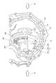
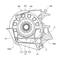
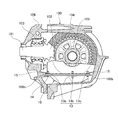
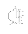
図1は、本発明の一実施の形態であるディファレンシャル装置の内部構成を模式的に示す斜視図であり、図2は、図1におけるA方向からディファレンシャル装置の内部構成を模式的に示す側面図であり、図3は、図1におけるB方向からディファレンシャル装置の内部構成を模式的に示す側面図である。 FIG. 1 is a perspective view schematically showing an internal configuration of a differential device according to an embodiment of the present invention, and FIG. 2 is a side view schematically showing the internal configuration of the differential device from the direction A in FIG. FIG. 3 is a side view schematically showing the internal configuration of the differential device from the direction B in FIG.
図1乃至図3に例示されるように、本実施の形態のディファレンシャル装置は、車両に搭載され、ディファレンシャル装置を構成する各部品を収容するコンバータケース100を有して構成されている。
As illustrated in FIGS. 1 to 3, the differential apparatus according to the present embodiment is configured to include a
このコンバータケース100には、後述するドライブシャフト101を収容するカバー部材106が組み付けられている。そして、コンバータケース100は、カバー部材106に当接する当接面に開口部を有しており、箱型をなして形成されている。
The
すなわち、本実施の形態のディファレンシャル装置は、コンバータケース100とカバー部材106とによりディファレンシャル装置を構成する各部品を収容している。これらコンバータケース100とカバー部材106とは、複数のボルトにより連結されている。
That is, in the differential device of the present embodiment, the
そして、コンバータケース100とカバー部材106とが組み付けられた内部には、上述したように、ディファレンシャル装置を構成する各部品が収容され、このディファレンシャル装置の主たる構成として、ドライブシャフト101、ドライブピニオンギヤ102、リングギヤ104及びディファレンシャルケース105が収容されている。
As described above, the components constituting the differential device are housed in the assembly in which the
本実施の形態において、ドライブシャフト101には、図示しない推進軸が締結されている。この推進軸は、図示しない変速装置により所望のトルクと回転数に変換されたエンジン(駆動源)の動力をドライブシャフト101に伝達している。
In the present embodiment, a drive shaft (not shown) is fastened to the
ドライブシャフト101の端部には、ドライブピニオンギヤ102が設けられている。そして、ドライブピニオンギヤ102は、ベアリング103を介してドライブシャフト101に支持されている。すなわち、ドライブピニオンギヤ102は、ドライブシャフト101の回転に対し、相対回転可能に支持されている。
A
また、コンバータケース100には、上述したように、ディファレンシャルケース105が収容されている。そして、ディファレンシャルケース105の内部には、図示しないピニオンシャフトが取り付けられている。
Further, as described above, the
このピニオンシャフトには、二つのピニオンギヤが回転可能に取り付けられている。これら二つのピニオンギヤは、左右の駆動輪に連結される図示しない車軸にそれぞれに取り付けられた図示しないべベルギヤに噛合して配設されている。 Two pinion gears are rotatably attached to the pinion shaft. These two pinion gears are arranged so as to mesh with bevel gears (not shown) attached to axles (not shown) connected to the left and right drive wheels, respectively.
また、ディファレンシャルケース105には、リングギヤ104が複数のボルト(締結部材)によって固定されている。そして、ディファレンシャルケース105は、図示しないベアリングによりコンバータケース100に支持されている。すなわち、リングギヤ104及びディファレンシャルケース105は、ドライブシャフト101の回転に伴い、回転可能に配設されている。
In addition, the
リングギヤ104は、上述したように、ディファレンシャルケース105と一体に回転し、ディファレンシャルケース105のその内部に設けられたピニオンギヤの公転を可能にしている。これにより、ディファレンシャルケース105の回転力は、ピニオンギヤからべベルギヤを介して車軸に伝達され、車軸の回転駆動を可能にしている。
As described above, the
本実施の形態において、コンバータケース100の底部には、ディファレンシャル装置及び変速装置を潤滑する潤滑油が貯留されている。本実施の形態のディファレンシャル装置は、リングギヤ104の回転に起因して掻き上げられた潤滑油を収容するバッフルプレート10を備えて構成されている。
In the present embodiment, the bottom of
このため、リングギヤ104の一部は潤滑油に浸されている。これにより、リングギヤ104の回転に起因して潤滑油が掻き上げられる。このように、リングギヤ104の回転に起因して潤滑油が掻き上げられることで、ドライブピニオンギヤ102とリングギヤ104との噛合部が潤滑される。
For this reason, a part of the
また、掻き上げられた潤滑油は、ディファレンシャルケース105に設けられた図示しない潤滑油導入孔を介してディファレンシャルケース105内に導入され、ディファレンシャルケース105内に配設されたピニオンギヤとべベルギヤとの間を潤滑する。
Further, the scraped lubricating oil is introduced into the
バッフルプレート10は、上述したように、コンバータケース100の内部に設けられ、リングギヤ104の下方側を覆うように配置されている。このバッフルプレート10は、リングギヤ104の外郭に沿った形状をなして形成されている。
As described above, the
このため、バッフルプレート10は、コンバータケース100の底部に滞留する潤滑油からリングギヤ104を離設可能にしている。すなわち、バッフルプレート10は、コンバータケース100の底部に貯留された潤滑油に対して、リングギヤ104の接触面積を低減させている。
For this reason, the
このように、バッフルプレート10がコンバータケース100の底部に貯留された潤滑油に対して、リングギヤ104の接触面積を低減させているため、リングギヤ104が回転する際に生じる攪拌抵抗を低減させることができる。
Thus, since the
本実施の形態において、バッフルプレート10は、リングギヤ104の回転軸に対し、直交方向に沿って配設された第1の棒状部材12及び第2の棒状部材14をさらに備えて構成されている。
In the present embodiment, the
そして、バッフルプレート10の一方面側には、第1の棒状部材12を挿通可能に支持するリブ部11a,11b,11cが一体に形成されている。また、バッフルプレート10の他方面側には、第2の棒状部材14を挿通可能に支持する複数のリブ部13a,13b,13cが一体に形成されている。
On one side of the
このリブ部11a,11b,11cは、板状をなして形成され、リングギヤ104の回転軸に沿って延設されている。なお、本実施の形態において、リブ部11a,11b,11cは、板状をなして形成されているが、この形状を限定されず、例えば、リブ部11a,11b,11cの内部を中空状に形成しても良い。
The
リブ部11a,11b,11cのそれぞれには、第1の棒状部材12を挿通可能な挿通孔が形成されている。すなわち、リブ部11a,11b,11cに第1の棒状部材12を挿通させることで、第1の棒状部材12がリングギヤ104の回転軸に対し、直交方向に沿って配設されている。
Each of the
また、リブ部13a,13b,13cも、リブ部11a,11b,11cと同様に、板状をなして形成され、リングギヤ104の回転軸に沿って延設されている。なお、本実施の形態において、リブ部13a,13b,13cも、板状をなして形成されているが、この形状に限定されず、リブ部13a,13b,13cの内部を中空状に形成しても良い。
The
そして、リブ部13a,13b,13cのそれぞれには、リブ部11a,11b,11cと同様に、第2の棒状部材14を挿通可能な挿通孔が形成されている。すなわち、リブ部13a,13b,13cに第2の棒状部材14を挿通させることで、第2の棒状部材14がリングギヤ104の回転軸に対し、直交方向に沿って配設されている。
And the
このように、バッフルプレート10の一方面側及び他方面側に沿って第1の棒状部材12及び第2の棒状部材14が配設され、これら第1の棒状部材12及び第2の棒状部材14をリブ部11a,11b,11c及びリブ部13a,13b,13cにより支持することで、バッフルプレート10の剛性を高めることができる。
As described above, the first rod-shaped
また、本実施の形態のバッフルプレート10は、第1の棒状部材12及び第2の棒状部材14を備え、バッフルプレート10自体の剛性を高めることで、異音の発生を抑止することができる。
Moreover, the
また、第1の棒状部材12の両端は、コンバータケース100のボス部100a及びカバー部材106のボス部106aに挿通されている。第2の棒状部材14も第1の棒状部材12と同様に、コンバータケース100のボス部100b及びカバー部材106のボス部106bに挿通されている。
Further, both ends of the first rod-shaped
このように、第1の棒状部材12及び第2の棒状部材14の両端がコンバータケース100及びカバー部材106に挟まれて固定されているため、バッフルプレート10を所望の位置に保持して位置決めを行うことが可能になる。また、バッフルプレート10を所望の位置に保持して位置ずれを抑えることが可能になる。
Thus, since both ends of the 1st rod-shaped
このため、バッフルプレート10とリングギヤ104との間隔を維持することが可能になる。これにより、リングギヤ104の攪拌抵抗を低減させることができる。そして、リングギヤ104の攪拌抵抗を低減させることで、リングギヤ104を回動させるためにかかる燃料の消費量を抑えることができ、燃費向上代を向上させることができる。
For this reason, the distance between the
また、本実施の形態のバッフルプレート10は、コンバータケース100及びカバー部材106に当接する当接面15を有して形成されている。すなわち、バッフルプレート10は、第1の棒状部材12及び第2の棒状部材14に加えて、バッフルプレート10自体がコンバータケース100及びカバー部材106により挟持されている。
Further, the
このように、バッフルプレート10をコンバータケース100及びカバー部材106に挟みこんで支持することで、バッフルプレート10を所望の位置に保持して位置決めを行うことが可能になる。また、バッフルプレート10を所望の位置に保持して位置ずれを抑えることが可能になる。
In this way, by sandwiching and supporting the
このため、バッフルプレート10とリングギヤ104との間隔を維持することが可能になり、リングギヤ104の攪拌抵抗をより確実に低減することができる。そして、リングギヤ104の攪拌抵抗を低減させることで、リングギヤ104を回動させるためにかかる燃料の消費量を抑えることができ、燃費向上代を向上させることができる。
For this reason, it becomes possible to maintain the space | interval of the
また、本実施の形態のバッフルプレート10は、このバッフルプレート10を支持する第1の棒状部材12及び第2の棒状部材14をコンバータケース100及びカバー部材106により挟み込んで支持されるとともに、バッフルプレート10自体をコンバータケース100及びカバー部材106により挟み込んで支持されることで、バッフルプレート10を組み付けるための部品を必要とせずに、バッフルプレート10とリングギヤ104との間隔を一定に保つことが可能になる。
In addition, the
このように、コンバータケース100にバッフルプレート10を組み付けるための部品を必要としないため、部品の脱落などによる異物噛み込みを予防することができる。
As described above, since a part for assembling the
そして、コンバータケース100にバッフルプレート10を組み付けるための部品を必要とすることなく、バッフルプレート10とリングギヤ104との間隔を一定に保つことが可能になるため、バッフルプレート10を位置決めするために複雑な構造とすることなく、容易に組み付けることができる。
And since it becomes possible to keep the space | interval of the
以上、本実施の形態によれば、リングギヤ104とバッフルプレート10との間隔を維持する位置を保つことで、リングギヤ104がコンバータケース100内の潤滑油を掻き上げる際、必要以上に潤滑油を掻き上げることなく、リングギヤ104にかかる攪拌抵抗を低減させることができる。
As described above, according to the present embodiment, by maintaining the position where the gap between the
(実施の形態2)
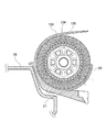
次に、本発明の他の実施の形態である車両用変速装置の潤滑構造について、図4及び図5を用いて説明する。図4は、本発明の他の実施の形態に係るディファレンシャル装置の内部構成を模式的に示す側面図であり、図5は、本発明の他の実施の形態に係るバッフルプレート20の構成を模式的に示す平面図である。
(Embodiment 2)
Next, a lubricating structure of a vehicle transmission apparatus according to another embodiment of the present invention will be described with reference to FIGS. FIG. 4 is a side view schematically showing an internal configuration of a differential apparatus according to another embodiment of the present invention, and FIG. 5 schematically shows a configuration of a
なお、本実施の形態の車両用変速装置の潤滑構造は、上述の実施の形態1に対して、バッフルプレート20に切り欠き27が形成された点が異なり、他の構成は、同様である。したがって、実施の形態と同一又は相当する部分には、同様の符号を付してその説明を省略する。
The lubricating structure of the vehicle transmission of the present embodiment is different from that of the first embodiment described above in that the
本実施の形態において、バッフルプレート20には、リングギヤ104の回転方向に沿った面に切り欠き27が形成されている。具体的には、切り欠き27は、リングギヤ104の回転方向に沿った面のうち、下方側の面に形成されている。
In the present embodiment, the
この切り欠き27は、バッフルプレート10とリングギヤ104との歯当り状態を確認する役目を果たしている。また、他方では、切り欠き27は、車両のレイアウト上、クロスメンバ29とディファレンシャル装置とを近設させる際、コンバータケース100内にバッフルプレート20を収容するための役目を果たしている。
This
また、図5に例示されるように、切り欠き27の隅切り部28は、略円形状をなして形成されている。このように、切り欠き27の隅切り部28が略円形状をなして形成されることで、この隅切り部28のひび割れを予防している。
Further, as illustrated in FIG. 5, the corner cut
本実施の形態のバッフルプレート20には、上述したように、切り欠き27が形成されている。このバッフルプレート20には、リングギヤ104の回転軸に対し、直交方向に延設して配置され、バッフルプレート20を補剛する第1の棒状部材22及び第2の棒状部材24が配設されている。
As described above, the
そして、バッフルプレート20の一方側面には、第1の棒状部材22を挿通可能に支持するリブ部21a,21b,21cがバッフルプレート20に一体に形成されている。また、バッフルプレート20の他方側面には、第2の棒状部材24を挿通可能に支持するリブ部23a,23b,23cがバッフルプレート20に一体に形成されている。
On one side surface of the
このように、バッフルプレート20の一方側面及び他方側面に第1の棒状部材22及び第2の棒状部材24が配設されることで、切り欠き27の口開きを抑えることができる。すなわち、バッフルプレート20の一方面側及び他方面側に第1の棒状部材22及び第2の棒状部材24が配設されることで、バッフルプレート20自体の剛性を高めることができる。
As described above, the first rod-
また、本実施の形態のバッフルプレート20も、上述の実施の形態1と同様に、第1の棒状部材22及び第2の棒状部材24を備え、バッフルプレート20自体の剛性を高めることで、異音の発生を抑止することができる。
Further, the
また、第1の棒状部材22の両端は、コンバータケース100のボス部100a及びカバー部材106のボス部106aに挿通されている。第2の棒状部材24もコンバータケース100のボス部100b及びカバー部材106のボス部106bに挿通されている。
Further, both ends of the first rod-shaped
このように、第1の棒状部材22及び第2の棒状部材24の両端がコンバータケース100及びカバー部材106に挟まれて固定されているため、バッフルプレート10を所望の位置に保持して位置決めを行うことが可能になる。また、バッフルプレート10を所望の位置に保持して位置ずれを抑えることが可能になる。
Thus, since both ends of the first rod-
このため、バッフルプレート20とリングギヤ104との間隔を維持することが可能になる。これにより、リングギヤ104の攪拌抵抗を低減させることができる。そして、リングギヤ104の攪拌抵抗を低減させることで、リングギヤ104を回動させるためにかかる燃料の消費量を抑えることができ、燃費向上代を向上させることができる。
For this reason, the distance between the
また、本実施の形態のバッフルプレート20は、上述の実施の形態1と同様に、コンバータケース100及びカバー部材106に当接する当接面25を有して形成されている。
Further, the
すなわち、バッフルプレート20は、第1の棒状部材22及び第2の棒状部材24に加えて、バッフルプレート20自体がコンバータケース100及びカバー部材106により挟持されている。
That is, the
このように、バッフルプレート20をコンバータケース100及びカバー部材106に挟みこんで支持することで、バッフルプレート20を所望の位置に保持して位置決めを行うことが可能になる。また、バッフルプレート20を所望の位置に保持して位置ずれを抑えることが可能になる。
As described above, the
このため、バッフルプレート20とリングギヤ104との間隔を維持することが可能になり、リングギヤ104の攪拌抵抗をより確実に低減することができる。そして、リングギヤ104の攪拌抵抗を低減させることで、リングギヤ104を回動させるためにかかる燃料の消費量を抑えることができ、燃費向上代を向上させることができる。
For this reason, it becomes possible to maintain the space | interval of the
また、本実施の形態のバッフルプレート20は、このバッフルプレート20を支持する第1の棒状部材22及び第2の棒状部材24をコンバータケース100及びカバー部材106により挟み込んで支持されるとともに、バッフルプレート20自体をコンバータケース100及びカバー部材106により挟み込んで支持されることで、バッフルプレート20を組み付けるための部品を必要とせずに、バッフルプレート20とリングギヤ104との間隔を一定に保つことが可能になる。
Further, the
このように、コンバータケース100にバッフルプレート20を組み付けるための部品を必要としないため、部品の脱落などによる異物噛み込みを予防することができる。
In this way, since a part for assembling the
そして、コンバータケース100にバッフルプレート20を組み付けるための部品を必要とすることなく、バッフルプレート20とリングギヤ104との間隔を一定に保つことが可能になるため、バッフルプレート20を位置決めするために複雑な構造とすることなく、容易に組み付けることができる。
And since it becomes possible to keep the space | interval of the
このように、バッフルプレート20に切り欠き21が必要な場合であっても、本実施の形態のバッフルプレート20は、リングギヤ104とバッフルプレート20との間隔を維持する位置を保つことで、リングギヤ104がコンバータケース100内の潤滑油を掻き上げる際、必要以上に潤滑油を掻き上げることなく、リングギヤ104にかかる攪拌抵抗を低減させることができる。
As described above, even when the notch 21 is necessary in the
10 バッフルプレート
11 リブ部
12 第1の棒状部材
13 リブ部
14 第2の棒状部材
15 当接面
20 バッフルプレート
21 リブ部
22 第1の棒状部材
23 リブ部
24 第2の棒状部材
27 切り欠き
28 隅切り部
29 クロスメンバ
100 コンバータケース
101 ドライブシャフト
102 ドライブピニオンギヤ
103 ベアリング
104 リングギヤ
105 ディファレンシャルケース
106 カバー部材
DESCRIPTION OF
Claims (5)
前記リングギヤを覆うように配置され、前記コンバータケース内の潤滑油の油面から前記リングギヤを離設可能なバッフルプレートを有し、
前記バッフルプレートは、前記リングギヤとの間隔を一定に支持する支持手段を具備し、
前記支持手段は、前記リングギヤの回転軸に対し、直交方向に延設して配置される棒状部材と、
前記バッフルプレートに一体に形成され、前記棒状部材を挿通可能に支持するリブ部と、をさらに具備すること、
を特徴とする車両用変速装置の潤滑構造。 At least a ring gear that is housed in a converter case that constitutes the outer shell of the differential device, and that constitutes a part of the differential device, and the lubricating oil in the converter case is fed to the differential device due to the rotational operation of the ring gear. A lubricating structure for a vehicle transmission that introduces and lubricates the differential device,
A baffle plate disposed so as to cover the ring gear and capable of separating the ring gear from the oil level of the lubricating oil in the converter case;
The baffle plate includes support means for supporting a constant distance from the ring gear ,
The support means is a rod-shaped member arranged extending in a direction orthogonal to the rotation axis of the ring gear;
A rib portion that is integrally formed with the baffle plate and supports the rod-shaped member so that the rod-shaped member can be inserted ;
A lubricating structure for a transmission for a vehicle.
前記リングギヤを覆うように配置され、前記コンバータケース内の潤滑油の油面から前記リングギヤを離設可能なバッフルプレートを有し、A baffle plate disposed so as to cover the ring gear and capable of separating the ring gear from the oil level of the lubricating oil in the converter case;
前記バッフルプレートは、前記リングギヤとの間隔を一定に支持する支持手段を具備し、The baffle plate includes support means for supporting a constant distance from the ring gear,
前記支持手段は、前記リングギヤの回転軸に対し、直交方向に延設して配置され、前記バッフルプレートを補剛する棒状部材と、The support means is disposed extending in a direction orthogonal to the rotation axis of the ring gear, and a rod-shaped member that stiffens the baffle plate;
前記バッフルプレートに一体に形成され、前記棒状部材を挿通可能に支持するリブ部と、をさらに具備すること、 A rib portion that is integrally formed with the baffle plate and supports the rod-shaped member so that the rod-shaped member can be inserted;
を特徴とする車両用変速装置の潤滑構造。 A lubricating structure for a transmission for a vehicle.
を特徴とする請求項1又は2記載の車両用変速装置の潤滑構造。 The rod-shaped member is sandwiched and fixed by the converter case and a cover member that covers the inside of the converter case,
The lubricating structure for a transmission for a vehicle according to claim 1 or 2 .
を特徴とする請求項3記載の車両用変速装置の潤滑構造。 The support means functions by sandwiching the baffle plate between the converter case and the cover member;
The lubricating structure for a vehicle transmission according to claim 3.
を特徴とする請求項1乃至4の何れか一項に記載の車両用変速装置の潤滑構造。
The baffle plate has a notch on a surface along the rotation direction of the ring gear, and the rod-shaped member is disposed in the vicinity of the notch,
The lubricating structure for a transmission for a vehicle according to any one of claims 1 to 4 .
Priority Applications (1)
| Application Number | Priority Date | Filing Date | Title |
|---|---|---|---|
| JP2010209555A JP5534603B2 (en) | 2010-09-17 | 2010-09-17 | Lubricating structure for vehicle transmission |
Applications Claiming Priority (1)
| Application Number | Priority Date | Filing Date | Title |
|---|---|---|---|
| JP2010209555A JP5534603B2 (en) | 2010-09-17 | 2010-09-17 | Lubricating structure for vehicle transmission |
Publications (2)
| Publication Number | Publication Date |
|---|---|
| JP2012062995A JP2012062995A (en) | 2012-03-29 |
| JP5534603B2 true JP5534603B2 (en) | 2014-07-02 |
Family
ID=46058901
Family Applications (1)
| Application Number | Title | Priority Date | Filing Date |
|---|---|---|---|
| JP2010209555A Expired - Fee Related JP5534603B2 (en) | 2010-09-17 | 2010-09-17 | Lubricating structure for vehicle transmission |
Country Status (1)
| Country | Link |
|---|---|
| JP (1) | JP5534603B2 (en) |
Families Citing this family (8)
| Publication number | Priority date | Publication date | Assignee | Title |
|---|---|---|---|---|
| CN104487740B (en) * | 2012-07-24 | 2017-05-03 | 本田技研工业株式会社 | Baffle plate and transmission with same |
| CN105247249B (en) | 2013-06-28 | 2018-04-06 | 爱信艾达株式会社 | power transmission device |
| JP6426400B2 (en) * | 2014-08-19 | 2018-11-21 | 株式会社Subaru | Transmission for vehicle |
| JP6488158B2 (en) * | 2015-03-09 | 2019-03-20 | 株式会社Subaru | Differential equipment |
| KR101836691B1 (en) * | 2016-09-05 | 2018-03-09 | 현대자동차주식회사 | Lubricating apparatus of differential for vehicle |
| US11098654B2 (en) * | 2019-03-15 | 2021-08-24 | Hamilton Sundstrand Corporation | Hydraulic unit gear shrouds |
| DE102022213413A1 (en) * | 2022-12-12 | 2024-06-13 | Zf Friedrichshafen Ag | Oil drip tray for a gearbox with parking lock and gearbox with parking lock |
| GB2643383A (en) * | 2024-08-06 | 2026-02-18 | Jaguar Land Rover Ltd | Electric vehicle differential |
Family Cites Families (2)
| Publication number | Priority date | Publication date | Assignee | Title |
|---|---|---|---|---|
| JPS63180767U (en) * | 1987-05-15 | 1988-11-22 | ||
| JPH02101165U (en) * | 1989-01-27 | 1990-08-13 |
-
2010
- 2010-09-17 JP JP2010209555A patent/JP5534603B2/en not_active Expired - Fee Related
Also Published As
| Publication number | Publication date |
|---|---|
| JP2012062995A (en) | 2012-03-29 |
Similar Documents
| Publication | Publication Date | Title |
|---|---|---|
| JP5534603B2 (en) | Lubricating structure for vehicle transmission | |
| CN108237893B (en) | Hybrid vehicle and lubrication structure for hybrid vehicle | |
| JP6580726B2 (en) | Power transmission device | |
| CN114375375B (en) | transmission | |
| JP4671267B2 (en) | Oil leakage prevention device for automatic transmission | |
| JP2009216189A (en) | Combined planetary gear drive apparatus | |
| JP6168236B2 (en) | Final drive device | |
| JP7596049B2 (en) | Power transmission | |
| JPWO2019208641A1 (en) | Vehicle power unit | |
| JP5952665B2 (en) | Lubrication and breather structure of power transmission equipment | |
| JP6534414B2 (en) | Power plant | |
| JP2006162039A (en) | Transmission for automobile or the like | |
| JP2020112246A (en) | Lubrication structure for hybrid vehicle driving device | |
| EP2187099B1 (en) | Lubrication structure of gear train encased in gear case | |
| JP6787155B2 (en) | Lubrication structure of reduction gear | |
| JP2019143744A (en) | Drive unit | |
| JP2015132314A (en) | Differential gear lubrication structure | |
| JP2006183717A (en) | Differential equipment | |
| JP6683063B2 (en) | Lubrication structure of power transmission device | |
| CN110296205B (en) | Lubricating structure of planetary gear mechanism | |
| JP2018189136A (en) | Power equipment | |
| WO2021048939A1 (en) | Transmission device | |
| JP7219274B2 (en) | Lubrication structure of power transmission device | |
| JP2012255493A (en) | Power transmission device | |
| JP2006250259A (en) | Lubrication structure for gear device |
Legal Events
| Date | Code | Title | Description |
|---|---|---|---|
| A621 | Written request for application examination |
Free format text: JAPANESE INTERMEDIATE CODE: A621 Effective date: 20130520 |
|
| A131 | Notification of reasons for refusal |
Free format text: JAPANESE INTERMEDIATE CODE: A131 Effective date: 20131224 |
|
| A977 | Report on retrieval |
Free format text: JAPANESE INTERMEDIATE CODE: A971007 Effective date: 20131227 |
|
| A521 | Request for written amendment filed |
Free format text: JAPANESE INTERMEDIATE CODE: A523 Effective date: 20140218 |
|
| TRDD | Decision of grant or rejection written | ||
| A01 | Written decision to grant a patent or to grant a registration (utility model) |
Free format text: JAPANESE INTERMEDIATE CODE: A01 Effective date: 20140325 |
|
| A61 | First payment of annual fees (during grant procedure) |
Free format text: JAPANESE INTERMEDIATE CODE: A61 Effective date: 20140421 |
|
| R150 | Certificate of patent or registration of utility model |
Ref document number: 5534603 Country of ref document: JP Free format text: JAPANESE INTERMEDIATE CODE: R150 |
|
| S531 | Written request for registration of change of domicile |
Free format text: JAPANESE INTERMEDIATE CODE: R313531 |
|
| R350 | Written notification of registration of transfer |
Free format text: JAPANESE INTERMEDIATE CODE: R350 |
|
| R250 | Receipt of annual fees |
Free format text: JAPANESE INTERMEDIATE CODE: R250 |
|
| S533 | Written request for registration of change of name |
Free format text: JAPANESE INTERMEDIATE CODE: R313533 |
|
| R350 | Written notification of registration of transfer |
Free format text: JAPANESE INTERMEDIATE CODE: R350 |
|
| R250 | Receipt of annual fees |
Free format text: JAPANESE INTERMEDIATE CODE: R250 |
|
| R250 | Receipt of annual fees |
Free format text: JAPANESE INTERMEDIATE CODE: R250 |
|
| R250 | Receipt of annual fees |
Free format text: JAPANESE INTERMEDIATE CODE: R250 |
|
| R250 | Receipt of annual fees |
Free format text: JAPANESE INTERMEDIATE CODE: R250 |
|
| R250 | Receipt of annual fees |
Free format text: JAPANESE INTERMEDIATE CODE: R250 |
|
| LAPS | Cancellation because of no payment of annual fees |