JP5533239B2 - Pneumatic tire - Google Patents
Pneumatic tire Download PDFInfo
- Publication number
- JP5533239B2 JP5533239B2 JP2010114059A JP2010114059A JP5533239B2 JP 5533239 B2 JP5533239 B2 JP 5533239B2 JP 2010114059 A JP2010114059 A JP 2010114059A JP 2010114059 A JP2010114059 A JP 2010114059A JP 5533239 B2 JP5533239 B2 JP 5533239B2
- Authority
- JP
- Japan
- Prior art keywords
- narrow groove
- recess
- groove
- opening
- tread surface
- Prior art date
- Legal status (The legal status is an assumption and is not a legal conclusion. Google has not performed a legal analysis and makes no representation as to the accuracy of the status listed.)
- Expired - Fee Related
Links
Images


Description
本発明は、トレッド面に細溝を備えた空気入りタイヤに関する。 The present invention relates to a pneumatic tire having a narrow groove on a tread surface.
スタッドレスタイヤには、エッジ効果を高めるためトレッド面に小さい幅の細溝が多数設けられている。
この細溝は、エッジ効果に加え、幅の大きい溝で排除しきれなかった水を取り込む排水機能も発揮している。
Studless tires are provided with a large number of narrow grooves having a small width on the tread surface in order to enhance the edge effect.
In addition to the edge effect, the narrow groove also exhibits a drainage function for taking in water that could not be excluded by the wide groove.
一方、細溝の幅が小さくなると、スタッドレスタイヤはサマータイヤに比べトレッドゴムが柔らかいため、タイヤ接地時の荷重負荷により細溝の開口部が閉塞され易い。
そして細溝の開口部が閉塞されると、路面から水を取り込みにくく、また、溝内に取り込んだ水を排出しにくくなるため、排水機能を向上しウェット性能を向上する上で改善の余地があった。
本発明は前記事情に鑑み案出されたものであって、本発明の目的は、細溝の形状を工夫することにより、細溝の開口部が閉塞された場合においてもウェット性能を向上できる空気入りタイヤを提供することにある。
On the other hand, when the width of the narrow groove is reduced, the tread rubber of the studless tire is softer than that of the summer tire, so that the opening of the narrow groove is likely to be blocked by a load load at the time of tire contact.
If the opening of the narrow groove is closed, it is difficult to take in water from the road surface, and it is difficult to discharge water taken into the groove, so there is room for improvement in improving the drainage function and improving wet performance. there were.
The present invention has been devised in view of the above circumstances, and an object of the present invention is to improve the wet performance even when the opening of the narrow groove is closed by devising the shape of the narrow groove. The purpose is to provide tires.
前記目的を達成するため本発明は、トレッド面に開口部を介して開放されるようにトレッド面に形成され、タイヤ接地時の荷重負荷により前記開口部が閉塞される細溝を備えた空気入りタイヤにおいて、前記細溝は、幅が3.0mm以上5.0mm未満であり、前記細溝を構成する互いに平行して対向する壁面の一方または双方に、前記開口部が閉塞された状態で前記細溝の底部寄りの箇所に連通する前記トレッド面に開放された凹部が前記細溝の延在方向に間隔をおいて複数設けられ、前記壁面の、トレッド面に直交する法線に対する角度θは、壁面の下端が互いに近づく方向の傾斜角度を−(マイナス)とし、互いに離れる方向の傾斜角度を+(プラス)とすると、−5度≦θ≦+5度であり、より好ましくは0度≦θ≦3度であり、前記細溝の幅をaとし、前記凹部が対向する壁面から最も離れた方向における前記凹部の底部までの寸法をbとし、前記細溝の延在方向に沿った前記凹部の幅をcとし、隣り合う前記凹部の間で前記凹部が形成されていない壁面の前記細溝の延在方向に沿った寸法をdとした場合、a〜dは、0.3≦a/b≦0.9(式1)および0.3≦c/d≦0.9(式2)を満たしていることを特徴とする。 In order to achieve the above-mentioned object, the present invention provides a pneumatic system provided with a narrow groove formed on a tread surface so as to be opened through the opening portion, and the opening portion being closed by a load applied at the time of tire contact. In the tire, the narrow groove has a width of 3.0 mm or more and less than 5.0 mm, and the opening is closed on one or both of the parallel facing walls constituting the narrow groove. fine grooves opened recess on the tread surface that communicates with the portion of the bottom near the plurality et been at intervals in the extending direction of the narrow groove of the wall surface, the angle θ relative to the normal perpendicular to the tread surface Is −5 degrees ≦ θ ≦ + 5 degrees, more preferably 0 degrees ≦ when the inclination angle in the direction in which the lower ends of the wall surfaces approach each other is − (minus) and the inclination angle in the direction away from each other is + (plus). θ ≦ 3 degrees, The width of the groove is a, the dimension to the bottom of the recess in the direction farthest from the wall surface facing the recess is b, and the width of the recess along the extending direction of the narrow groove is c. When the dimension along the extending direction of the narrow groove on the wall surface where the concave portion is not formed between the concave portions is d, a to d are 0.3 ≦ a / b ≦ 0.9 (formula 1 ) And 0.3 ≦ c / d ≦ 0.9 (formula 2) .
本発明では、タイヤ接地時に開口部が閉塞された状態でも、路面上の水を凹部から細溝内に取り込み易くし、また、溝内に取り込んだ水を凹部から排出し易くなるため、排水機能を向上し、ウェット性能を向上できる。 In the present invention, even when the opening is closed at the time of tire contact, water on the road surface can be easily taken into the narrow groove from the recessed portion, and the water taken into the groove can be easily discharged from the recessed portion. Can improve wet performance.
以下、本発明の実施の形態を図面にしたがって説明する。
図6に示すように、スタッドレスタイヤ10のトレッド部12には、トレッド部12のショルダー部14寄りの箇所にタイヤ周方向に延在する一対の縦溝16Aが設けられ、またこの縦溝16Aに交差する横溝16Bがタイヤ周方向に間隔をおいて設けられている。さらに、各横溝16Bの内端間を接続する傾斜した細溝18が設けられ、さらに、この細溝18と縦溝16Aの間で横溝16Bの中間部間を接続する傾斜した細溝20が設けられている。
トレッド部12には、それら縦溝16A、横溝16B、細溝18、20により、タイヤ赤道C上を延在するセンターリブ12Aと、センターリブ12Aの両側にそれぞれブロックが周方向に並べられた第1ブロック列12B、第2ブロック列12C、第3ブロック列12Dからなる陸部24が区画され、陸部24のトレッド面1202にサイプ26が設けられている。
本発明の対象となる細溝は、本実施の形態では、細溝18と縦溝16Aの間で横溝16Bの中間部間を接続する傾斜した細溝20である。
Hereinafter, embodiments of the present invention will be described with reference to the drawings.
As shown in FIG. 6, the
The
In the present embodiment, the narrow groove that is the subject of the present invention is an inclined
トレッド面1202を構成するトレッド部のゴムの硬度は、20℃の雰囲気においてJIS 6253のAタイプデュロメータで測定した硬度で42以上57以下である。
ゴムの硬度が42に満たないと、細溝20のエッジ効果が不十分となり、ゴムの硬度が57を超えると、細溝20がつぶれにくくなるためである。
The hardness of the rubber in the tread portion constituting the
This is because if the hardness of the rubber is less than 42, the edge effect of the
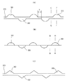
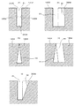
細溝20は、図1(A)、図2(E)に示すように、互いに対向する壁面2002、壁面2002の下部を接続する底面2004で形成されており、トレッド面1202に開口部2006を介して開放されている。
細溝20の幅は小さく、図1(B)、図2(G)に示すように、壁面2002をなすブロック状の部分1204がタイヤ接地時の荷重負荷により変形して開口部2006が閉塞される。
本発明において対象となる細溝20は、幅が1.0mmから5.0mmが好ましい。細溝20の幅が1.0mm未満であると、排水機能が十分に発揮されず、また、幅が5.0mmを超えると、タイヤ接地時に開口部2006が閉塞される可能性が低くなるためである。
細溝20は、直線状に延在していてもよく、曲線状あるいはジクザク状に延在していてもよい。
As shown in FIGS. 1A and 2E, the
The
In the present invention, the
The
また、図3に示すように、壁面2002の、トレッド面1202に直交する法線22に対する角度θは、壁面2002の下端が互いに近づく方向の傾斜角度を−(マイナス)とし、互いに離れる方向の傾斜角度を+(プラス)とすると、−5度≦θ≦+5度が好ましく、0度≦θ≦3度がより好ましい。角度θが−5度以下では、開口部2006が閉塞された際の溝体積を確保できず、ウェット性能を向上させる上で不利がある。また、角度θが5度を超えると、タイヤ加硫後の金型からの抜けが悪くなり、ブロック欠けなどの製造上の問題が生じる。したがって、トレッド面1202に直交する法線22に対する角度θが上述の範囲内にあれば、壁面2002をなすブロック状の部分1204がタイヤ接地時の荷重負荷により変形して開口部2006が閉塞された際に、細溝20内の溝体積を確保でき、ウェット性能を向上する上で有利となる。
Further, as shown in FIG. 3, the angle θ of the
図1(A)、図2(F)に示すように、細溝20を構成する互いに対向する壁面2002の一方または双方に、細溝20の延在方向に間隔をおきトレッド面1202に開放された複数の凹部30が設けられている。
凹部30は、図1(B)、図2(G)に示すように、壁面2002をなすブロック状の部分1204がタイヤ接地時の荷重負荷により変形して開口部2006が閉塞された状態で、図2(H)に示すように、細溝20の底面2004寄りの箇所と連通されるものである。
これにより、開口部2006が閉塞された状態でも、路面上の水を凹部30から細溝20内に取り込み易くし、また、細溝20内に取り込んだ水を凹部30から排出し易くなるため、排水機能を向上し、ウェット性能が向上される。
図2(F)に示すように、凹部30の深さは、細溝20と同じ深さで形成してもよく、図2(I)に示すように、細溝20から離れるにつれて次第に深さを減少させてもよい。凹部30の深さを細溝20と同じ深さで形成する場合には、凹部30は、例えば、円筒面からなる壁面3002で形成され、また、凹部30の深さを細溝20から離れるにつれて次第に深さを減少させる場合には、凹部30は、例えば、円錐面からなる壁面3002で形成される。
なお、細溝20の深さ方向と直交する平面で切断した凹部30の輪郭は、図1(A)、(B)に示す円弧状に限定されず、図1(C)に示す三角形や、四角形などであってもよい。
As shown in FIGS. 1 (A) and 2 (F), one or both of
As shown in FIGS. 1 (B) and 2 (G), the
Thereby, even when the
As shown in FIG. 2 (F), the depth of the
In addition, the outline of the
凹部30を対向する壁面2002の双方に設ける場合、それら凹部30を対向するように設けてもよく、あるいは、それら凹部30が干渉しないように細溝20の延在方向に位相をずらして設けてもよい。
本実施の形態では、対向する壁面2002の双方にそれら凹部30が干渉しないように細溝20の延在方向に位相をずらして設けられている。
凹部30を対向する壁面2002の双方に設ける場合、凹部30が存在していない壁面2002どうしが対向する箇所が設けられる。凹部30が存在していない壁面2002どうしが対向する箇所の細溝20の延在方向に沿った長さL(図1(A)参照)は、2mm以上が好ましい。長さLが2mm以下では、開口部2006が閉塞された際に、壁面2002をなすブロック状の部分1204どうしが互いに支えきれず、凹部30の体積が減少するためである。
When the
In the present embodiment, the phase is shifted in the extending direction of the
When providing the recessed
また、図4に示すように、細溝20の幅をaとし、凹部30が対向する壁面2002から最も離れた方向における凹部30の底部までの寸法をbとし、細溝20の延在方向に沿った凹部30の幅をcとし、隣り合う凹部30の間で凹部30が形成されていない壁面2002の細溝20の延在方向に沿った寸法をdとした場合、下記の式1と式2を満たしていることが好ましい。
0.3≦a/b≦0.9 (式1)
0.3≦c/d≦0.9 (式2)
これは、a/b>0.9の場合、および0.3>c/dの場合には、細溝20に対する凹部30の体積比が小さいため、排水機能が期待できず、WET性能を確保し難くなるためである。
また、a/b<0.3の場合にはブロック剛性が低下し、また、0.9<c/dの場合には、開口部2006が閉塞される際に接触する凹部30が存在していない壁面2002どうしが対向する箇所の細溝20の延在方向に沿った長さLが短くなる。そのため、開口部2006が閉塞される際に壁面2002をなすブロック状の部分1204の変形量が多くなって凹部30自体の体積も減少し、排水機能が期待できなくなるためである。
Further, as shown in FIG. 4, the width of the
0.3 ≦ a / b ≦ 0.9 (Formula 1)
0.3 ≦ c / d ≦ 0.9 (Formula 2)
This is because when a / b> 0.9 and 0.3> c / d, the volume ratio of the
Further, when a / b <0.3, the block rigidity is reduced, and when 0.9 <c / d, there is a
図6に示すトレッドパターンで図5に示す仕様の細溝20、凹部30(図1に示す円弧状の凹部30)が形成された、タイヤサイズが225/65R17のスタッドレスタイヤを試作し、WET旋回性能について評価を行なった。
評価はWET旋回試験路で行ない、水深を1mmとし、旋回半径を30mとし、グリップ走行範囲内の最高の速度で5周旋回し、1周毎の速度のうち最大値と最小値を除き、3周分の速度の平均値を算出した。そして、算出結果を従来例を100とした指数で表示し、数値が大きいほどWET旋回性能が良好であることを示す。
A prototype studless tire with a tire size of 225 / 65R17 in which the tread pattern shown in FIG. 6 and the
The evaluation is performed on the WET turning test road, the water depth is 1 mm, the turning radius is 30 m, the turning speed is 5 laps at the highest speed within the grip travel range, and the maximum and minimum values are excluded from the speed for each lap. The average speed of minutes was calculated. The calculation result is displayed as an index with the conventional example being 100, and the larger the value, the better the WET turning performance.
図5から、タイヤ接地時の荷重負荷により開口部2006が閉塞される細溝20に凹部30を設けると、WET旋回性能を向上できることが明らかである。
また、実施例2〜5から、上記の寸法a〜dが上記の式1と式2を満たしていると、WET旋回性能を向上する上で有利であることが明らかである。
From FIG. 5, it is clear that the WET turning performance can be improved by providing the
Moreover, it is clear from Examples 2-5 that it is advantageous when improving said WET turning performance that said dimension ad satisfy | fills said
20……細溝、2002……壁面、2006……開口部、30……凹部。 20... Fine groove, 2002... Wall surface, 2006.
Claims (3)
前記細溝は、幅が3.0mm以上5.0mm未満であり、
前記細溝を構成する互いに平行して対向する壁面の一方または双方に、前記開口部が閉塞された状態で前記細溝の底部寄りの箇所に連通する前記トレッド面に開放された凹部が前記細溝の延在方向に間隔をおいて複数設けられ、
前記壁面の、トレッド面に直交する法線に対する角度θは、壁面の下端が互いに近づく方向の傾斜角度を−(マイナス)とし、互いに離れる方向の傾斜角度を+(プラス)とすると、−5度≦θ≦+5度であり、より好ましくは0度≦θ≦3度であり、
前記細溝の幅をaとし、前記凹部が対向する壁面から最も離れた方向における前記凹部の底部までの寸法をbとし、前記細溝の延在方向に沿った前記凹部の幅をcとし、隣り合う前記凹部の間で前記凹部が形成されていない壁面の前記細溝の延在方向に沿った寸法をdとした場合、a〜dは、0.3≦a/b≦0.9(式1)および0.3≦c/d≦0.9(式2)を満たしている、
ことを特徴とする空気入りタイヤ。 In a pneumatic tire provided with a narrow groove that is formed on a tread surface so as to be opened to the tread surface via an opening, and the opening is closed by a load load at the time of tire contact,
The narrow groove has a width of 3.0 mm or more and less than 5.0 mm,
On one or both of the walls facing each other in parallel with each other, the recessed portion opened to the tread surface communicating with the portion near the bottom of the narrow groove with the opening closed is formed on the narrow groove. plurality et been at intervals in the extending direction of the groove,
The angle θ of the wall surface with respect to the normal line orthogonal to the tread surface is −5 degrees when the inclination angle in the direction in which the lower ends of the wall surfaces approach each other is − (minus) and the inclination angle in the direction away from each other is + (plus). ≦ θ ≦ + 5 degrees, more preferably 0 degree ≦ θ ≦ 3 degrees,
The width of the narrow groove is a, the dimension to the bottom of the recess in the direction farthest from the wall facing the recess is b, the width of the recess along the extending direction of the narrow groove is c, When the dimension along the extending direction of the narrow groove on the wall surface where the concave portion is not formed between the adjacent concave portions is defined as d, a to d are 0.3 ≦ a / b ≦ 0.9 ( Satisfying Formula 1) and 0.3 ≦ c / d ≦ 0.9 (Formula 2),
A pneumatic tire characterized by that.
ことを特徴とする請求項1記載の空気入りタイヤ。 The hardness of the rubber of the tread portion constituting the tread surface is 42 or more and 57 or less in hardness measured with an A type durometer of JIS 6253 in an atmosphere of 20 ° C.,
The pneumatic tire according to claim 1.
ことを特徴とする請求項1または2記載の空気入りタイヤ。 The pneumatic tire according to claim 1 or 2, characterized in that.
Priority Applications (1)
| Application Number | Priority Date | Filing Date | Title |
|---|---|---|---|
| JP2010114059A JP5533239B2 (en) | 2010-05-18 | 2010-05-18 | Pneumatic tire |
Applications Claiming Priority (1)
| Application Number | Priority Date | Filing Date | Title |
|---|---|---|---|
| JP2010114059A JP5533239B2 (en) | 2010-05-18 | 2010-05-18 | Pneumatic tire |
Publications (2)
| Publication Number | Publication Date |
|---|---|
| JP2011240800A JP2011240800A (en) | 2011-12-01 |
| JP5533239B2 true JP5533239B2 (en) | 2014-06-25 |
Family
ID=45407898
Family Applications (1)
| Application Number | Title | Priority Date | Filing Date |
|---|---|---|---|
| JP2010114059A Expired - Fee Related JP5533239B2 (en) | 2010-05-18 | 2010-05-18 | Pneumatic tire |
Country Status (1)
| Country | Link |
|---|---|
| JP (1) | JP5533239B2 (en) |
Families Citing this family (5)
| Publication number | Priority date | Publication date | Assignee | Title |
|---|---|---|---|---|
| CN102848859B (en) * | 2012-09-14 | 2015-06-03 | 江苏大学 | Automobile tire with anti-skidding and noise-reducing performances |
| JP6123405B2 (en) * | 2013-03-26 | 2017-05-10 | 横浜ゴム株式会社 | Pneumatic tire |
| KR101782621B1 (en) * | 2016-06-28 | 2017-09-27 | 넥센타이어 주식회사 | Tire |
| KR101853845B1 (en) * | 2016-12-14 | 2018-05-02 | 넥센타이어 주식회사 | Pneumatic tire |
| JP7399679B2 (en) * | 2019-10-29 | 2023-12-18 | 株式会社ブリヂストン | pneumatic tires |
Family Cites Families (4)
| Publication number | Priority date | Publication date | Assignee | Title |
|---|---|---|---|---|
| JPS63297106A (en) * | 1987-05-26 | 1988-12-05 | Sumitomo Rubber Ind Ltd | Spikeless tire |
| JPH07276923A (en) * | 1994-04-06 | 1995-10-24 | Ohtsu Tire & Rubber Co Ltd :The | Tire |
| JP5099914B2 (en) * | 2008-10-03 | 2012-12-19 | 東洋ゴム工業株式会社 | Pneumatic tire |
| JP2010105509A (en) * | 2008-10-29 | 2010-05-13 | Yokohama Rubber Co Ltd:The | Pneumatic tire |
-
2010
- 2010-05-18 JP JP2010114059A patent/JP5533239B2/en not_active Expired - Fee Related
Also Published As
| Publication number | Publication date |
|---|---|
| JP2011240800A (en) | 2011-12-01 |
Similar Documents
| Publication | Publication Date | Title |
|---|---|---|
| JP4669052B2 (en) | Pneumatic tire | |
| US8307867B2 (en) | Pneumatic tire with tread including sipe having wide portions located alternately on both side walls | |
| JP4397956B1 (en) | Pneumatic tire | |
| JP5005684B2 (en) | Running tread with tread pattern with notches | |
| JP5270417B2 (en) | Pneumatic tire | |
| JP5239504B2 (en) | Pneumatic tire | |
| JP5797506B2 (en) | Pneumatic tire | |
| JP4215751B2 (en) | Pneumatic tire | |
| JP2017505261A (en) | Tread for heavy vehicle tires | |
| JP2014523366A (en) | Tire having a tread with a cut including a wide portion and a narrow portion | |
| JP4740301B2 (en) | Pneumatic tire | |
| JP5533239B2 (en) | Pneumatic tire | |
| CN109219530B (en) | Winter tyre | |
| JP6139843B2 (en) | Pneumatic tire | |
| JP4958361B2 (en) | Tire tread pattern | |
| JP5679105B2 (en) | Pneumatic tire and its vulcanization mold | |
| JP4548551B2 (en) | Pneumatic tire | |
| CN101578186A (en) | Pneumatic tire | |
| CN105764708A (en) | Tire for winter | |
| JP2008290521A (en) | Pneumatic tire | |
| CA2911606A1 (en) | Pneumatic tire | |
| JP2013244854A (en) | Pneumatic tire | |
| JP4735137B2 (en) | Pneumatic tire | |
| JP4255165B2 (en) | Pneumatic tire and its vulcanization mold | |
| CN204149781U (en) | Air-inflation tyre |
Legal Events
| Date | Code | Title | Description |
|---|---|---|---|
| A621 | Written request for application examination |
Free format text: JAPANESE INTERMEDIATE CODE: A621 Effective date: 20130510 |
|
| A977 | Report on retrieval |
Free format text: JAPANESE INTERMEDIATE CODE: A971007 Effective date: 20131218 |
|
| A131 | Notification of reasons for refusal |
Free format text: JAPANESE INTERMEDIATE CODE: A131 Effective date: 20140107 |
|
| A521 | Request for written amendment filed |
Free format text: JAPANESE INTERMEDIATE CODE: A523 Effective date: 20140310 |
|
| TRDD | Decision of grant or rejection written | ||
| A01 | Written decision to grant a patent or to grant a registration (utility model) |
Free format text: JAPANESE INTERMEDIATE CODE: A01 Effective date: 20140401 |
|
| R150 | Certificate of patent or registration of utility model |
Ref document number: 5533239 Country of ref document: JP Free format text: JAPANESE INTERMEDIATE CODE: R150 |
|
| A61 | First payment of annual fees (during grant procedure) |
Free format text: JAPANESE INTERMEDIATE CODE: A61 Effective date: 20140414 |
|
| R250 | Receipt of annual fees |
Free format text: JAPANESE INTERMEDIATE CODE: R250 |
|
| R250 | Receipt of annual fees |
Free format text: JAPANESE INTERMEDIATE CODE: R250 |
|
| R250 | Receipt of annual fees |
Free format text: JAPANESE INTERMEDIATE CODE: R250 |
|
| R250 | Receipt of annual fees |
Free format text: JAPANESE INTERMEDIATE CODE: R250 |
|
| R250 | Receipt of annual fees |
Free format text: JAPANESE INTERMEDIATE CODE: R250 |
|
| LAPS | Cancellation because of no payment of annual fees |