JP5526629B2 - Superconducting coil body manufacturing method and superconducting coil body - Google Patents
Superconducting coil body manufacturing method and superconducting coil body Download PDFInfo
- Publication number
- JP5526629B2 JP5526629B2 JP2009159751A JP2009159751A JP5526629B2 JP 5526629 B2 JP5526629 B2 JP 5526629B2 JP 2009159751 A JP2009159751 A JP 2009159751A JP 2009159751 A JP2009159751 A JP 2009159751A JP 5526629 B2 JP5526629 B2 JP 5526629B2
- Authority
- JP
- Japan
- Prior art keywords
- superconducting
- tape
- superconducting coil
- wire
- coils
- Prior art date
- Legal status (The legal status is an assumption and is not a legal conclusion. Google has not performed a legal analysis and makes no representation as to the accuracy of the status listed.)
- Active
Links
Images


Description
本発明は、超電導コイル体の製造方法および超電導コイル体に関する。 The present invention relates to a method for manufacturing a superconducting coil body and a superconducting coil body.
従来より、超電導マグネットなどの超電導機器は、複数の超電導コイルを積層することにより作製される。超電導コイルは、巻枠と、この巻枠に超電導線材を巻き付けることにより製造される。超電導コイルに用いられる超電導線材は、たとえば非特許文献1および2などが挙げられる。非特許文献1の超電導線材の平均厚さは、0.255〜0.285mmであることが記載されている。非特許文献2の超電導線材の平均厚さは、0.30±0.04mmであることが記載されている。 Conventionally, superconducting equipment such as a superconducting magnet is manufactured by laminating a plurality of superconducting coils. The superconducting coil is manufactured by winding a winding frame and a superconducting wire around the winding frame. Examples of the superconducting wire used for the superconducting coil include Non-Patent Documents 1 and 2. It is described that the average thickness of the superconducting wire of Non-Patent Document 1 is 0.255 to 0.285 mm. Non-Patent Document 2 describes that the superconducting wire has an average thickness of 0.30 ± 0.04 mm.
上記非特許文献1および2の超電導線材の平均厚さは、0.03〜0.08mmのばらつきがある。このように、超電導線材の平均厚さのばらつきが大きいと、これらの超電導線材を用いて作製した超電導コイルの特性が劣化するという問題がある。その理由について、以下説明する。 The average thickness of the superconducting wires of Non-Patent Documents 1 and 2 varies from 0.03 to 0.08 mm. Thus, when the dispersion | variation in the average thickness of a superconducting wire is large, there exists a problem that the characteristic of the superconducting coil produced using these superconducting wires deteriorates. The reason will be described below.
具体的には、図10に示すように、平均厚さが異なる超電導線材210、220を同じ巻き数で巻枠213に巻き付けて超電導コイルを形成すると、それぞれの超電導コイルの外形が異なる。このため、図10の領域Rでそれぞれの超電導線材を接続すると、外形の差により超電導線材がひっかかって折れてしまう場合がある。超電導線材が折れてしまうと、超電導コイルの特性が劣化してしまう。
Specifically, as shown in FIG. 10, when
そこで、本発明の目的は、特性の劣化を抑制した超電導コイル体の製造方法および超電導コイル体を提供することである。 Therefore, an object of the present invention is to provide a method of manufacturing a superconducting coil body and a superconducting coil body in which deterioration of characteristics is suppressed.
本発明の超電導コイル体の製造方法は、以下の工程を備えている。複数の超電導線材を準備する。超電導線材の中から平均厚みが最も大きな第1の超電導線材を特定し、第1の超電導線材を巻くことにより形成される第1の超電導コイルの外形を設計し、第1の超電導線材を巻くことにより第1の超電導コイルを形成する。第1の超電導コイルとの外縁の差が5mm以下となるように、かつ第1の超電導コイルの巻き数と同じ巻き数になるように、残部の超電導線材をテープ状部材と共に巻くことにより形成される残部の超電導コイルの外形を設計し、残部の超電導線材をテープ状部材と共に巻くことにより残部の超電導コイルを形成する。第1の超電導コイルと、残部の超電導コイルとを複数の超電導線材の特性が劣化しないように接続する。 The manufacturing method of the superconducting coil body of the present invention includes the following steps. Prepare multiple superconducting wires. The first superconducting wire having the largest average thickness is identified from the superconducting wires, the outer shape of the first superconducting coil formed by winding the first superconducting wire is designed, and the first superconducting wire is wound. Thus, the first superconducting coil is formed. It is formed by winding the remaining superconducting wire together with the tape-like member so that the difference in outer edge with the first superconducting coil is 5 mm or less and the same number of turns as the first superconducting coil. The remaining superconducting coil is designed, and the remaining superconducting wire is wound with a tape-shaped member to form the remaining superconducting coil. The first superconducting coil and the remaining superconducting coil are connected so that the characteristics of the plurality of superconducting wires are not deteriorated .
本発明の超電導コイル体の製造方法によれば、テープ状部材を用いて残部の超電導コイルの外形を調整して、平均厚みが最も大きな超電導線材を用いて形成された第1の超電導コイルの外形と同じ外形にしている。このため、第1の超電導コイルと残部の超電導コイルとの外形をそろえることができる。これにより、第1の超電導コイルと残部の超電導コイルとの接続において、超電導線材がひっかかることを抑制できる。したがって、超電導線材が折れることを抑制できるので、これらの超電導線材を用いて形成された第1の超電導コイルと残部の超電導とが接続された超電導コイル体の特性の劣化を抑制することができる。 According to the method for manufacturing a superconducting coil body of the present invention, the outer shape of the remaining superconducting coil is adjusted using a tape-like member, and the outer shape of the first superconducting coil formed using the superconducting wire having the largest average thickness. It has the same external shape. For this reason, it is possible to align the outer shapes of the first superconducting coil and the remaining superconducting coil. Thereby, it is possible to prevent the superconducting wire from being caught in the connection between the first superconducting coil and the remaining superconducting coil. Therefore, since the superconducting wire can be prevented from being broken, it is possible to suppress the deterioration of the characteristics of the superconducting coil body in which the first superconducting coil formed using these superconducting wires and the remaining superconducting material are connected.
本発明に従った超電導コイル体は、絶縁材で被覆された、平均厚みが少なくとも1つは異なる複数の超電導線材を用いて形成された複数の超電導コイルが複数の超電導線材の特性が劣化しないように接続された超電導コイル体であって、複数の超電導コイルの外縁の差は5mm以下であり、複数の超電導コイルでは、超電導線材とテープ状部材とが共巻きされており、複数の超電導コイルのうちの1つの超電導コイルにおけるテープ状部材の巻き数は、複数の超電導コイルのうちの他の1つの超電導コイルにおけるテープ状部材の巻き数と異なる。
本発明の一の局面における超電導コイル体は、絶縁材で被覆された、平均厚みが少なくとも1つは異なる複数の超電導線材を用いて形成された複数の超電導コイルが複数の超電導線材の特性が劣化しないように接続された超電導コイル体であって、複数の超電導コイルの外縁の差は5mm以下であり、複数の超電導コイルのうちの少なくとも1つの超電導コイルは、超電導線材とテープ状部材とが共巻きされており、かつ複数の超電導コイルのうちの少なくとも1つの超電導コイルは、テープ状部材が共巻きされていない状態で超電導線材が巻かれていることを特徴としている。
The superconducting coil body according to the present invention has a plurality of superconducting coils formed of a plurality of superconducting wires coated with an insulating material and having an average thickness of at least one different so that characteristics of the plurality of superconducting wires are not deteriorated. A plurality of superconducting coils , wherein the difference between the outer edges of the plurality of superconducting coils is 5 mm or less . In the plurality of superconducting coils, the superconducting wire and the tape-like member are wound together, The number of turns of the tape-like member in one of the superconducting coils is different from the number of turns of the tape-like member in the other one of the plurality of superconducting coils.
In the superconducting coil body according to one aspect of the present invention, a plurality of superconducting coils formed using a plurality of superconducting wires coated with an insulating material and having an average thickness different from each other are deteriorated in characteristics of the plurality of superconducting wires. The superconducting coil bodies are connected so that the difference between the outer edges of the plurality of superconducting coils is 5 mm or less , and at least one superconducting coil of the plurality of superconducting coils is composed of a superconducting wire and a tape-like member. The superconducting wire is wound, and at least one superconducting coil of the plurality of superconducting coils is characterized in that the superconducting wire is wound in a state where the tape-like member is not co-wound.
本発明の一の局面における超電導コイル体によれば、超電導線材とテープ状部材とを共巻きすることで、複数の超電導コイルの外形を同じにしている。このため、超電導線材がひっかかることを抑制して、複数の超電導コイルを接続することができる。したがって、複数の超電導コイルの接続において超電導線材が折れることを抑制できるので、超電導コイル体の特性の劣化を抑制することができる。 According to the superconducting coil body in one aspect of the present invention, the superconducting wire and the tape-like member are wound together to make the outer shapes of the plurality of superconducting coils the same. For this reason, it can suppress that a superconducting wire is caught and can connect a some superconducting coil. Therefore, since the superconducting wire can be prevented from being broken at the connection of a plurality of superconducting coils, the deterioration of the characteristics of the superconducting coil body can be suppressed.
本発明の他の局面における超電導コイル体は、超電導線材とテープ状部材とが共巻きされた複数の超電導コイルが接続された超電導コイル体であって、複数の超電導コイルは、平均厚みが少なくとも1つは異なる複数の超電導線材を用いて形成され、複数の超電導コイルは、複数の超電導線材の特性が劣化しないように接続され、複数の超電導コイルの外縁の差は5mm以下であり、複数の超電導コイルにおいて共巻きされたテープ状部材の平均厚みが異なることを特徴としている。 A superconducting coil body according to another aspect of the present invention is a superconducting coil body in which a plurality of superconducting coils in which a superconducting wire and a tape-like member are wound together are connected , and the plurality of superconducting coils have an average thickness of at least 1. Are formed using a plurality of different superconducting wires, the plurality of superconducting coils are connected so that the characteristics of the plurality of superconducting wires are not deteriorated, and the difference between the outer edges of the plurality of superconducting coils is 5 mm or less. It is characterized in that the average thicknesses of the tape-like members wound together in the coil are different.
本発明の他の局面における超電導コイル体によれば、平均厚みが異なるテープ状部材を共巻きすることで、複数の超電導コイルの外形を同じにしている。このため、超電導線材がひっかかることを抑制して、複数の超電導コイルを接続することができる。したがって、複数の超電導コイルの接続において超電導線材が折れることを抑制できるので、超電導コイル体の特性の劣化を抑制することができる。 According to the superconducting coil body in another aspect of the present invention, the outer shapes of the plurality of superconducting coils are made the same by co-winding tape-like members having different average thicknesses. For this reason, it can suppress that a superconducting wire is caught and can connect a some superconducting coil. Therefore, since the superconducting wire can be prevented from being broken at the connection of a plurality of superconducting coils, the deterioration of the characteristics of the superconducting coil body can be suppressed.
上記超電導コイル体の製造方法において好ましくは、第1の超電導コイルを形成する工程では、第1の超電導線材をテープ状部材と共に巻くことにより第1の超電導コイルを形成し、第1の超電導コイルにおけるテープ状部材の巻き数は、残部の超電導コイルにおける少なくとも1つのテープ状部材の巻き数と異なる。
上記超電導コイル体の製造方法において好ましくは、残部の超電導コイルを形成する工程では、テープ状部材として、ポリイミドテープ、プリプレグテープ、およびポリアミドテープからなる群より選ばれた少なくとも一種を用いる。
Preferably, in the method of manufacturing the superconducting coil body, in the step of forming the first superconducting coil, the first superconducting wire is wound together with the tape-shaped member to form the first superconducting coil, and the first superconducting coil The number of turns of the tape-like member is different from the number of turns of at least one tape-like member in the remaining superconducting coil.
Preferably, in the method of manufacturing the superconducting coil body, in the step of forming the remaining superconducting coil, at least one selected from the group consisting of a polyimide tape, a prepreg tape, and a polyamide tape is used as the tape-like member.
本発明の一および他の局面における超電導コイル体において好ましくは、テープ状部材は、ポリイミドテープ、プリプレグテープ、およびポリアミドテープからなる群より選ばれた少なくとも一種である。 In the superconducting coil body according to one and other aspects of the present invention, preferably, the tape-shaped member is at least one selected from the group consisting of a polyimide tape, a prepreg tape, and a polyamide tape.
これらのテープ状部材は、絶縁性で、かつ低温での耐性を有している。このため、超電導コイルの短絡を防止でき、かつ超電導状態での耐性を向上することができる。 These tape-shaped members are insulative and have low-temperature resistance. For this reason, the short circuit of a superconducting coil can be prevented and the tolerance in a superconducting state can be improved.
上記超電導コイル体の製造方法において好ましくは、残部の超電導コイルを形成する工程では、残部の超電導線材の長さ方向の全てにおいて残部の超電導線材をテープ状部材と共に巻く。 Preferably, in the method of manufacturing the superconducting coil body, in the step of forming the remaining superconducting coil, the remaining superconducting wire is wound together with the tape-like member in the entire length of the remaining superconducting wire.
上記一および他の超電導コイル体において好ましくは、テープ状部材と共巻きされた超電導線材は、長さ方向の全てにおいてテープ状部材と共に巻かれている。 In the one and other superconducting coil bodies, preferably, the superconducting wire co-wound with the tape-like member is wound together with the tape-like member in all the length directions.
これにより、長さ方向の全てにおいてテープ状部材と共に巻かれた超電導線材を有する超電導コイルの電流密度を均一にすることができる。このため、磁場分布の均一化を向上できる。 Thereby, the current density of the superconducting coil having the superconducting wire wound together with the tape-like member in all the length directions can be made uniform. For this reason, the uniformity of the magnetic field distribution can be improved.
上記超電導コイル体の製造方法において好ましくは、残部の超電導コイルを形成する工程では、残部の超電導線材の長さ方向の一部において残部の超電導線材をテープ状部材と共に巻く。 Preferably, in the method of manufacturing the superconducting coil body, in the step of forming the remaining superconducting coil, the remaining superconducting wire is wound together with the tape-like member in a part of the remaining superconducting wire in the length direction.
上記一および他の局面における超電導コイル体において好ましくは、テープ状部材と共巻きされた超電導線材は、長さ方向の一部においてテープ状部材と共に巻かれている。 In the superconducting coil body according to the above and other aspects, preferably, the superconducting wire wound together with the tape-like member is wound together with the tape-like member in a part in the length direction.
これにより、超電導線材の厚み、テープ状部材の厚みなどによらずに、テープ状部材と共に巻かれた超電導コイルの外形を容易に調整できる。このため、超電導コイルを同じ外形に容易に形成することができる。 Thereby, the external shape of the superconducting coil wound with the tape-like member can be easily adjusted without depending on the thickness of the superconducting wire, the thickness of the tape-like member, or the like. For this reason, a superconducting coil can be easily formed in the same external shape.
以上より、本発明の超電導コイル体の製造方法および超電導コイル体によれば、特性の劣化を抑制することができる。 As described above, according to the method of manufacturing a superconducting coil body and the superconducting coil body of the present invention, it is possible to suppress deterioration of characteristics.
以下、図面に基づいて本発明の実施の形態を説明する。なお、以下の図面において同一または相当する部分には同一の参照符号を付し、その説明は繰り返さない。 Hereinafter, embodiments of the present invention will be described with reference to the drawings. In the following drawings, the same or corresponding parts are denoted by the same reference numerals, and description thereof will not be repeated.
(実施の形態1)
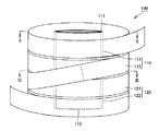
図1〜図5を参照して、本発明の一実施の形態における超電導コイル体100について説明する。本実施の形態における超電導コイル体100は、ダブルパンケーキ型コイルである。
(Embodiment 1)
A
具体的には、本実施の形態における超電導コイル体100は、図1〜図3に示すように、第1の超電導コイル110と、第2の超電導コイル120とを備えている。第1および第2の超電導コイル110、120の外形は同じである。図2に示すように、第1の超電導コイル110は、巻枠111と、巻枠111に巻き付けられた超電導線材112とを含む。第1の超電導コイル110は、テープ状部材が共巻きされていない状態で超電導線材112が巻かれている。図3に示すように、第2の超電導コイル120は、巻枠121と、巻枠121に巻き付けられた超電導線材122と、超電導線材122と共巻きされたテープ状部材123とを含む。本実施の形態では、第2の超電導コイル120は、長さ方向の全てにおいてテープ状部材123と共に巻かれている。超電導線材112、122は、最外周層において互いに接続されている。
Specifically, the
ここで、上記「第1および第2の超電導コイル110、120の外形は同じ」とは、第1の超電導コイル110の外縁と第2の超電導コイル120との外縁の差が、用いる超電導線材112、122の許容曲げ歪みの範囲内であることを意味する。この場合、超電導線材112、122の接続において超電導線材112、122の特性の劣化を抑制できる。外縁の差は、たとえば5mm以下であり、好ましくは1mm以下、より好ましくは0.3mm以下である。0.3mm以下の場合、超電導線材112、122の曲げ歪みを効果的に抑制できる。本実施の形態では第1および第2の超電導コイル110、120が円筒状であるので、第1および第2の超電導コイル110、120の外径R110、R120の差は、10mm以下である。第1および第2の超電導コイル110、120がレーストラック型であれば、第1および第2の超電導コイル110、120の長径および短径の差は、10mm以下である。
Here, “the outer shapes of the first and second
巻枠111、121は、たとえば内部が開口した円筒状である。なお、巻枠111、121の形状等は、特に限定されず、たとえばレーストラック形状であってもよい。巻枠111、121の外周には超電導線材112、122がそれぞれ巻回される。巻枠111、121を構成する材料は特に限定されないが、ステンレス鋼(SUS)または絶縁材料などを用いることができる。
The
超電導線材112、122は、巻枠111、121に巻き付けられて第1および第2の超電導コイル110、120を形成している。本実施の形態では図1に示すように、ダブルパンケーキ型コイルであるが、巻き型は特に限定されず、ダブルパンケーキ型コイル、シングルパンケーキ型コイル、超電導線材112、122がらせん状に巻かれてなるコイルなどを用いることができる。
超電導線材112、122はテープ状であり、図4に示すように、ビスマス(Bi)系の超電導線材を用いてもよく、図5に示すように、薄膜超電導線材を用いてもよい。
The
ビスマス系の超電導線材は、図4に示すように、長手方向に延びる複数本の超電導体112aと、複数の超電導体112aの全周を被覆するシース部112bと、シース部112bの全周を被覆する絶縁材112gとを有している。シース部112bは超電導体112aに接触している。複数本の超電導体112aの各々は、たとえばBi−Pb−Sr−Ca−Cu−O系の組成を有するビスマス系超電導体が好ましく、特に、(ビスマスと鉛):ストロンチウム:カルシウム:銅の原子比がほぼ2:2:2:3の比率で近似して表されるBi2223相を含む材質が最適である。なお、超電導体112aは、単数本であってもよい。シース部112bの材質は、たとえば銀や銀合金よりなっている。絶縁材112gは、他の超電導線材等と絶縁性を確保するために形成されている。絶縁材112gは、たとえばポリイミドテープなどを用いることができる。
As shown in FIG. 4, the bismuth-based superconducting wire covers a plurality of
薄膜超電導線材は、図5に示すように、基板112cと、中間層112dと、超電導層112eと、安定化層112fと、絶縁材112gとを有している。中間層112dは、基板112c上に接して設けられている。超電導層112eは、中間層112d上に接して設けられている。安定化層112fは、超電導層112e上に接して設けられている。絶縁材112gは、基板112c、中間層112d、超電導層112eおよび安定化層112fを有する積層体の外周全体を被覆している。
As shown in FIG. 5, the thin film superconducting wire has a substrate 112c, an
基板112cは、たとえばステンレス鋼、ニッケル合金(たとえばハステロイ)、または銀合金などの金属よりなっている。中間層112dは、たとえばイットリア安定化ジルコニア、酸化セリウム、酸化マグネシウムまたはチタン酸ストロンチウムなどよりなっている。なお、中間層112dは省略されてもよい。
The substrate 112c is made of a metal such as stainless steel, nickel alloy (for example, Hastelloy), or silver alloy. The
超電導層112eはたとえばRE123系超電導体よりなっている。RE123系超電導体とは、RExBayCuzO7-dにおいて、0.7≦x≦1.3、1.7≦y≦2.3、2.7≦z≦3.3であることを意味する。また、RE123系超電導体のREとは、希土類元素およびイットリウム元素の少なくともいずれかを含む材質を意味する。また、希土類元素としては、たとえばネオジム(Nd)、ガドリニウム(Gd)、ホルミニウム(Ho)、サマリウム(Sm)などが含まれる。RE123系超電導線材は、液体窒素温度(77.3K)での臨界電流密度がビスマス系の超電導線材よりも高いという利点を有している。また、低温下および一定磁場下における臨界電流値が高いという利点を有している。一方で、RE123系超電導体はビスマス系超電導体のようにシース部で被覆することができないので、配向金属基板上に気相法のみまたは液相法のみによって超電導体(超電導薄膜材料)を成膜する方法で製造される。
また、安定化層112fは、超電導層112eの表面保護のために設けられる層であり、たとえば銀や銅などよりなっている。安定化層112fは省略されてもよい。
The stabilizing
本実施の形態のBi系の超電導線材および薄膜超電導線材において、第1の超電導コイル110を構成する超電導線材112では絶縁材112gは省略されず、第2の超電導コイル120を構成する超電導線材122では絶縁材112gは省略されてもよい。
In the Bi-based superconducting wire and the thin film superconducting wire of the present embodiment, the insulating
テープ状部材123は、第1および第2の超電導コイル110、120の外形を同じにするために形成されている。本実施の形態では、第1の超電導コイル110を構成する超電導線材112の平均厚みは、第2の超電導コイル120を構成する超電導線材122の平均厚みよりも大きい。このため、テープ状部材123は、第1および第2の超電導コイル110、120の外形をそろえるために、第2の超電導線材122と共巻きされている。
The tape-
テープ状部材123は、絶縁性であっても導電性であってもよい。超電導線材122が絶縁材112gを有していない場合には、第1の超電導コイル120のターン間の短絡を防止する観点から、テープ状部材123は絶縁性であることが好ましい。このような材料として、ポリイミドテープ、プリプレグテープ(半硬化テープ)、およびポリアミドテープからなる群より選ばれた少なくとも一種であることが好ましい。これらの材料の厚みは薄いため、厚みを調整が容易である。ポリイミドテープは、たとえば10μm程度の厚みを有している。プリプレグテープおよびポリアミドテープは、たとえば50μm程度の厚みを有している。ポリアミドテープは、たとえばノーメックステープ(R)を用いることができる。また、第1および第2の超電導コイル110、120を樹脂に含浸させたときに、これらの材料は樹脂との親和性が高い。さらに、これらの材料は低温での耐性が高いため、超電導状態での耐性を向上できる。なお、テープ状部材123は、ガラスクロスなどの材料を用いてもよい。
The tape-
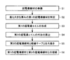
続いて、本実施の形態における超電導コイル体100の製造方法について説明する。まず、図1〜図6に示すように、複数の超電導線材112、122を準備する(ステップS1)。複数の超電導線材112、122は、図4または図5に示すような超電導線材を用いることができる。
Then, the manufacturing method of the
次に、複数の超電導線材112、122の中から平均厚みが最も大きな第1の超電導線材112を特定する(ステップS2)。平均厚みとは、長手方向に1m毎に50点以上測定した厚みの平均値を意味する。
Next, the
次に、第1の超電導線材112を巻くことにより第1の超電導コイル110を形成する(ステップS3)。ステップS3では、巻枠111に超電導線材112を巻き付ける。巻き付ける方法は特に限定されず、ダブルパンケーキ型、シングルパンケーキ型、らせん状などのように超電導線材112を巻枠111に巻き付ける。ステップS3を実施することにより、準備した複数の超電導線材の中から最も大きな外形の超電導コイルを形成することができる。
Next, a first
次に、第2の超電導線材112を用いたときの第2の超電導コイル120の外形を算出する(ステップS4)。ステップS4では、算出した外形と、第1の超電導コイル110の外形との差を考慮して、超電導線材122と共巻きするテープ状部材123の厚み、長さを決定する。
Next, the outer shape of the second
たとえば、第1の超電導線材112の平均厚みが0.34mmで、第2の超電導線材122の平均厚みが0.30mmの場合には、0.04mmの平均厚みを有するテープ状部材123を共巻きすることを決定する。
For example, when the average thickness of the
次に、第1の超電導コイル110の外形と同じ外形になるように、かつ第1の超電導コイル110の巻き数と同じ巻き数になるように、残部の超電導線材122をテープ状部材123と共に巻くことにより第2の超電導コイル120を形成する(ステップS5)。ステップS5では、ステップS4で決定したテープ状部材123と、超電導線材122とを重ね合わせた状態で、巻枠121に巻き付ける。共巻きする方法は、第1の超電導コイル110を構成する超電導線材110の巻き付ける方法と同様に、特に限定されない。
Next, the remaining
本実施の形態では、超電導線材122の長さ方向の全てにおいて超電導線材122をテープ状部材123と共に巻いている。このため、第2の超電導コイル120の電流密度は等しくなる。
In the present embodiment, the
次に、第1の超電導コイルと、残部の超電導コイルとを接続する(ステップS6)。このステップS6では、たとえば、第1および第2の超電導コイル110、120をスタックして、第1および第2の超電導コイル110、120の超電導線材112、122の端末部を引き出す。本実施の形態では、超電導線材112、122の最外周の端部を引き出して、互いに電気的に接続している。
Next, the first superconducting coil and the remaining superconducting coil are connected (step S6). In this step S6, for example, the first and second
以上の工程を実施することにより、図1〜図3に示す超電導コイル体100を製造することができる。なお、上述の製造方法は一例であり、別の工程を備えていてもよいし、工程の順序を変更してもよい。
By performing the above steps, the
続いて、本実施の形態の超電導コイル体100およびその製造方法の効果について説明する。
Next, the effects of the
本発明者は、図10に示すように厚みのばらつきのある超電導線材を用いて形成した複数の超電導コイルを接続すると、外形の差により超電導線材がひっかかって折れてしまう場合があることに着目した。そこで、本発明者は非特許文献2に開示されている超電導線材を用いて、円筒状の巻枠の内径が100mmで、300ターンの巻き数で超電導線材を巻き付けて超電導コイルを製造した。その結果、超電導線材の厚みが0.26mmの場合には256mmの外径となり、超電導線材の厚みが0.34mmの場合には304mmの外径となった。つまり、超電導線材の平均厚みのばらつきが0.08mmの場合には、超電導コイルの外径の差は48mmとなることを確認した。このため、それぞれの超電導コイルを接続すると、外径の差が大きいため、その段差により超電導線材がひっかかって折れてしまい、超電導コイルの特性が劣化するという問題があった。 As shown in FIG. 10, the present inventor paid attention to the fact that when a plurality of superconducting coils formed using a superconducting wire having a variation in thickness are connected, the superconducting wire may be caught and broken due to the difference in outer shape. . Therefore, the present inventor manufactured a superconducting coil by using the superconducting wire disclosed in Non-Patent Document 2 and winding the superconducting wire with the number of turns of 300 turns with the inner diameter of the cylindrical winding frame being 100 mm. As a result, the outer diameter was 256 mm when the thickness of the superconducting wire was 0.26 mm, and the outer diameter was 304 mm when the thickness of the superconducting wire was 0.34 mm. That is, when the variation in the average thickness of the superconducting wire was 0.08 mm, it was confirmed that the difference in the outer diameter of the superconducting coil was 48 mm. For this reason, when the respective superconducting coils are connected, the difference in outer diameter is large, so that there is a problem that the superconducting wire is caught and broken by the step and the characteristics of the superconducting coil deteriorate.
そこで、本実施の形態では、外径の最も大きい第1の超電導コイル110の外形と同じ外形になるように、かつ第1の超電導コイル110の巻き数と同じ巻き数になるように、残部の超電導線材(第2の超電導線材122)をテープ状部材123と共に巻くことにより残部の超電導コイル(第2の超電導コイル120)を形成している。これにより、第1の超電導コイル110と第2の超電導コイル120との外形をそろえることができる。このため、第1の超電導コイル110と第2の超電導コイル120との接続において、超電導線材112、122がひっかかることを抑制できる。したがって、超電導線材112、122が折れることを抑制できるので、これらの超電導線材112、122を用いて形成された第1の超電導コイル110と第2の超電導コイル120とが接続された超電導コイル体100の特性の劣化を抑制することができる。
Therefore, in the present embodiment, the remainder of the first
特に、巻き数が大きくなっても、テープ状部材123により、同じ外径の超電導コイルを作製できる。このため、超電導コイル体100の特性の劣化を抑制できる。
In particular, even when the number of turns increases, the superconducting coil having the same outer diameter can be produced by the tape-
また、第1の超電導コイル110と第2の超電導コイル120の巻き数(ターン数)が同じであるので、磁場の精度を向上できる。このため、本実施の形態における超電導コイル体100をMRI等に好適に用いることができる。
Moreover, since the number of turns (number of turns) of the first
また、本実施の形態では、平均厚みが最も大きい超電導線材112は、外周全体を被覆した絶縁材112gを有している。このため、第1の超電導コイル110は短絡を防止できるので、テープ状部材を共巻きせずに第1の超電導コイル110を形成することができる。この場合、第1の超電導コイル110を簡略化して形成することができる。
Moreover, in this Embodiment, the
ここで、本実施の形態では、超電導コイル体100として、第1および第2の超電導コイル110、120を接続した構造を例に挙げて説明したが、本発明の超電導コイル体は2つの超電導コイルの接続体に特に限定されない。本発明の超電導コイル体は、3つ以上の超電導コイルの接続体を含む。
Here, in the present embodiment, the
3つ以上の超電導コイルを接続した超電導コイル体は、たとえば図7に示すように、接続する超電導コイル間での外形が同じである。つまり、第1の超電導コイル110と第2の超電導コイル120との外縁の差D1が、超電導線材112、122の許容曲げ歪み以下(たとえば5mm以下)で、かつ第2の超電導コイル120と第3の超電導コイル130との外縁の差D2が超電導線材112、122の許容曲げ歪み以下(たとえば5mm以下)である。言い換えると、第1の超電導コイル110の外径R110と第2の超電導コイル120の外径R120との差は超電導線材112、122の許容曲げ歪みの2倍以下(たとえば10mm以下)で、第2の超電導コイル120の外径R120と第3の超電導コイル130の外径R130との差は超電導線材の許容曲げ歪みの2倍以下(たとえば10mm以下)である。
A superconducting coil body to which three or more superconducting coils are connected has the same outer shape between the superconducting coils to be connected, for example, as shown in FIG. That is, the difference D1 between the outer edges of the first
(実施の形態2)
図8を参照して、本実施の形態における超電導コイル体について説明する。本実施の形態における超電導コイル体は、実施の形態1の超電導コイル体と基本的には同様の構成を備えているが、図8に示すように、第1の超電導コイル110の構成において異なっている。
(Embodiment 2)
A superconducting coil body in the present embodiment will be described with reference to FIG. The superconducting coil body in the present embodiment has basically the same configuration as the superconducting coil body in the first embodiment, but differs in the configuration of the first
具体的には、第1の超電導コイル110は、超電導線材112と、超電導線材112と共巻きされたテープ状部材113とを含んでいる。第1の超電導コイル110を構成するテープ状部材113の平均厚みと、第2の超電導コイル120を構成するテープ状部材123の平均厚みとは異なっている。本実施の形態では、第1の超電導コイル110を構成する超電導線材112の平均厚みが第2の超電導コイル120を構成する超電導線材122の平均厚みよりも大きいため、第1の超電導コイル110を構成するテープ状部材113の平均厚みは第2の超電導コイル120を構成するテープ状部材123の平均厚みよりも小さい。
Specifically, the first
ここで、テープ状部材113、123の平均厚みとは、長手方向に1m毎に50点以上測定した厚みの平均値を意味する。
Here, the average thickness of the tape-
テープ状部材113のその他の構成は、実施の形態1で説明したテープ状部材123と同様であるので、その説明は繰り返さない。
Since the other structure of the tape-shaped
また、本実施の形態における超電導線材112は、図4および図5に示す絶縁材112gを含んでいてもよく、含んでいなくてもよい。
Moreover, the
続いて、本実施の形態における超電導コイル体の製造方法について説明する。本実施の形態における超電導コイル体の製造方法は、基本的には実施の形態1における超電導コイル体の製造方法と同様の構成を備えているが、第1の超電導コイル110の形成方法において異なっている。
Then, the manufacturing method of the superconducting coil body in this Embodiment is demonstrated. The method for manufacturing the superconducting coil body in the present embodiment basically has the same configuration as the method for manufacturing the superconducting coil body in the first embodiment, but differs in the method for forming the first
具体的には、複数の超電導線材112、122を準備する(ステップS1)。次に、最も大きな厚みの第1の超電導線材を特定する(ステップS2)。ステップS1およびS2は、実施の形態1のステップS1およびS2と同様であるので、その説明は繰り返さない。
Specifically, a plurality of
次に、第1および第2の超電導線材112、122から、第1および第2の超電導コイル110、120の外径を設計し、その外径になるように、第1および第2の超電導線材112と共巻きするテープ状部材113、123を特定する(ステップS4)。
Next, the outer diameters of the first and second
次に、第1の超電導線材112とテープ状部材113とを共巻きして、超電導コイル110を形成する(ステップS3)。また、第2の超電導線材122とテープ状部材123とを共巻きして、第2の超電導コイル120を形成する(ステップS5)。ステップS3、S5は、実施の形態1のステップS5と同様であるので、その説明は繰り返さない。
Next, the
次に、第1の超電導線材112と第2の超電導線材122とを接続する(ステップS6)。ステップS6は、実施の形態1のステップS6と同様であるので、その説明は繰り返さない。
Next, the
以上のステップS1〜S6を実施することにより、本実施の形態における超電導コイル体を製造することができる。 By performing the above steps S1 to S6, the superconducting coil body in the present embodiment can be manufactured.
本実施の形態における超電導コイル体およびその製造方法によれば、複数の超電導コイル(第1および第2の超電導コイル110、120)の外形は同じであり、複数の超電導コイル(第1および第2の超電導コイル110、120)において共巻きされたテープ状部材113、123の平均厚みが異なる。これにより、超電導線材112、122と共にテープ状部材113、123を巻くことにより、所望の外径で、かつ同じ外径の超電導コイル(第1および第2の超電導コイル110、120)を作製できる。したがって、特性の劣化を抑制し、かつ所望の大きさの超電導コイル体を製造することができる。
According to the superconducting coil body and the manufacturing method thereof in the present embodiment, the plurality of superconducting coils (first and second
ここで、本実施の形態では、第1の超電導コイル110において、超電導線材112は長さ方向の全てにおいてテープ状部材113と共に巻かれているが、長さ方向の一部においてテープ状部材113と共に巻かれていてもよい。
Here, in the present embodiment, in the first
(実施の形態3)
図9を参照して、本実施の形態における超電導コイル体について説明する。本実施の形態における超電導コイル体は、実施の形態1の超電導コイル体と基本的には同様の構成を備えているが、図9に示すように、第2の超電導コイル120の構成において異なっている。
(Embodiment 3)
With reference to FIG. 9, the superconducting coil body in the present embodiment will be described. The superconducting coil body in the present embodiment has basically the same configuration as the superconducting coil body in the first embodiment, but differs in the configuration of the second
具体的には、第2の超電導コイル120において、テープ状部材123と共巻きされた超電導線材122は、長さ方向の一部においてテープ状部材123と共に巻かれている。本実施の形態では、巻枠111側(内周側)にはテープ状部材が巻き付けられていない状態で超電導線材122が巻き付けられ、外周側にはテープ状部材が超電導線材122と共に巻き付けられている。なお、長さ方向の一部とは、外周側に特に限定されず、内周側であってもよく、中央部であってもよい。
Specifically, in the second
続いて、本実施の形態における超電導コイル体の製造方法について説明する。本実施の形態における超電導コイル体の製造方法は、基本的には実施の形態1および2の超電導コイル体の製造方法と同様であるが、第2の超電導コイル120の形成方法において異なっている。
Then, the manufacturing method of the superconducting coil body in this Embodiment is demonstrated. The method for manufacturing the superconducting coil body in the present embodiment is basically the same as the method for manufacturing the superconducting coil body in the first and second embodiments, but differs in the method for forming the second
具体的には、第2の超電導コイル120を形成するステップS4では、超電導線材122の長さ方向の一部において超電導線材122をテープ状部材123と共に巻く。本実施の形態では、超電導線材122のみを所定のターン数巻枠121に巻きつけた後、超電導線材122をテープ状部材123と共に巻き付ける。なお、超電導線材122の巻き始めのみにテープ状部材123を共巻してもよく、巻き始めおよび巻き終わりを避けて超電導線材122とテープ状部材123とを共巻きしてもよい。
Specifically, in step S <b> 4 for forming the second
本実施の形態における超電導コイル体およびその製造方法によれば、超電導線材122の長さ方向の一部において超電導線材122をテープ状部材123と共に巻いている。超電導線材112、122の厚み、テープ状部材123の厚みなどによらず、また所望の厚みのテープ状部材123が入手困難な場合であっても、テープ状部材123と共に巻かれた第2の超電導コイル120の外形を容易に調整できる。このため、超電導コイルを同じ外形に容易に形成することができる。
According to the superconducting coil body and the manufacturing method thereof in the present embodiment,
ここで、本実施の形態は、実施の形態2の超電導コイル体およびその製造方法にも適用できる。また、実施の形態2に適用した場合には、第2の超電導コイルのみでなく、第1の超電導コイルにも適用できる。 Here, the present embodiment can also be applied to the superconducting coil body and the manufacturing method thereof according to the second embodiment. Moreover, when applied to Embodiment 2, it is applicable not only to the second superconducting coil but also to the first superconducting coil.
以上のように本発明の実施の形態について説明を行なったが、各実施の形態の特徴を適宜組み合わせることも当初から予定している。また、今回開示された実施の形態はすべての点で例示であって制限的なものではないと考えられるべきである。本発明の範囲は上記した実施の形態ではなくて特許請求の範囲によって示され、特許請求の範囲と均等の意味および範囲内でのすべての変更が含まれることが意図される。 Although the embodiments of the present invention have been described as described above, it is also planned from the beginning to combine the features of each embodiment as appropriate. In addition, it should be considered that the embodiment disclosed this time is illustrative and not restrictive in all respects. The scope of the present invention is shown not by the above-described embodiment but by the scope of claims, and is intended to include all modifications within the meaning and scope equivalent to the scope of claims.
100 超電導コイル体、110 超電導コイル、111,121 巻枠、112,122 超電導線材、112a 超電導体、112b シース部、112c 基板、112d 中間層、112e 超電導層、112f 安定化層、112g 絶縁材、113,123 テープ状部材、120 第2の超電導コイル、130 第3の超電導コイル。 100 superconducting coil body, 110 superconducting coil, 111, 121 winding frame, 112, 122 superconducting wire, 112a superconductor, 112b sheath part, 112c substrate, 112d intermediate layer, 112e superconducting layer, 112f stabilization layer, 112g insulating material, 113 , 123 tape-shaped member, 120 second superconducting coil, 130 third superconducting coil.
Claims (11)
前記超電導線材の中から平均厚みが最も大きな第1の超電導線材を特定し、前記第1の超電導線材を巻くことにより形成される第1の超電導コイルの外形を設計し、前記第1の超電導線材を巻くことにより前記第1の超電導コイルを形成する工程と、
前記第1の超電導コイルとの外縁の差が5mm以下となるように、かつ前記第1の超電導コイルの巻き数と同じ巻き数になるように、残部の前記超電導線材をテープ状部材と共に巻くことにより形成される残部の超電導コイルの外形を設計し、残部の前記超電導線材を前記テープ状部材と共に巻くことにより前記残部の超電導コイルを形成する工程と、
前記第1の超電導コイルと、前記残部の超電導コイルとを前記複数の超電導線材の特性が劣化しないように接続する工程とを備えた、超電導コイル体の製造方法。 Preparing a plurality of superconducting wires;
A first superconducting wire having the largest average thickness is identified from among the superconducting wires, the outer shape of the first superconducting coil formed by winding the first superconducting wire is designed, and the first superconducting wire forming said Ri by the winding a first superconducting coil,
Winding the remaining superconducting wire together with the tape-like member so that the difference between the outer edges of the first superconducting coil is 5 mm or less and the number of turns is the same as the number of turns of the first superconducting coil. a step of designing the outer shape of the superconducting coils of the balance, the superconducting wire of the remainder to form a superconducting coil by Ri the remainder to be wound together with the tape-like member which is formed by,
A method of manufacturing a superconducting coil body, comprising: connecting the first superconducting coil and the remaining superconducting coil so that characteristics of the plurality of superconducting wires are not deteriorated .
前記第1の超電導コイルにおける前記テープ状部材の巻き数は、前記残部の超電導コイルにおける少なくとも1つの前記テープ状部材の巻き数と異なる、請求項1に記載の超電導コイル体の製造方法。 In the step of forming the first superconducting coil, the first superconducting coil is formed by winding the first superconducting wire together with a tape-shaped member,
2. The method of manufacturing a superconducting coil body according to claim 1, wherein the number of turns of the tape-like member in the first superconducting coil is different from the number of turns of at least one of the tape-like members in the remaining superconducting coil.
前記複数の超電導コイルの外縁の差は5mm以下であり、
前記複数の超電導コイルでは、前記超電導線材とテープ状部材とが共巻きされており、
前記複数の超電導コイルのうちの1つの超電導コイルにおける前記テープ状部材の巻き数は、前記複数の超電導コイルのうちの他の1つの超電導コイルにおける前記テープ状部材の巻き数と異なる、超電導コイル体。 A superconducting coil body in which a plurality of superconducting coils formed by using a plurality of superconducting wires having different average thicknesses and covered with an insulating material are connected so as not to deteriorate the characteristics of the plurality of superconducting wires. And
The difference between the outer edges of the plurality of superconducting coils is 5 mm or less ,
In the plurality of superconducting coils, the superconducting wire and the tape-shaped member are wound together,
The number of turns of the tape-like member in one superconducting coil of the plurality of superconducting coils is different from the number of turns of the tape-like member in another superconducting coil of the plurality of superconducting coils. .
前記複数の超電導コイルの外縁の差は5mm以下であり、
前記複数の超電導コイルのうちの少なくとも1つの超電導コイルは、前記超電導線材とテープ状部材とが共巻きされており、かつ前記複数の超電導コイルのうちの少なくとも1つの超電導コイルは、前記テープ状部材と共巻きされていない状態で前記超電導線材が巻かれていることを特徴としている、超電導コイル体。 A superconducting coil body in which a plurality of superconducting coils formed by using a plurality of superconducting wires having different average thicknesses and covered with an insulating material are connected so as not to deteriorate the characteristics of the plurality of superconducting wires. And
The difference between the outer edges of the plurality of superconducting coils is 5 mm or less ,
At least one superconducting coil of the plurality of superconducting coils has the superconducting wire and a tape-shaped member wound together, and at least one superconducting coil of the plurality of superconducting coils is the tape-shaped member. A superconducting coil body, wherein the superconducting wire is wound in a state where it is not co-wound.
前記複数の超電導コイルは、平均厚みが少なくとも1つは異なる複数の超電導線材を用いて形成され、
前記複数の超電導コイルは、前記複数の超電導線材の特性が劣化しないように接続され、
前記複数の超電導コイルの外縁の差は5mm以下であり、
前記複数の超電導コイルにおいて共巻きされた前記テープ状部材の平均厚みが異なることを特徴としている、超電導コイル体。 A superconducting coil body in which a plurality of superconducting coils in which a superconducting wire and a tape-like member are wound together are connected ,
The plurality of superconducting coils are formed using a plurality of superconducting wires having at least one average thickness different from each other,
The plurality of superconducting coils are connected so as not to deteriorate the characteristics of the plurality of superconducting wires,
The difference between the outer edges of the plurality of superconducting coils is 5 mm or less ,
A superconducting coil body, wherein the tape-shaped members wound together in the plurality of superconducting coils have different average thicknesses.
Priority Applications (1)
| Application Number | Priority Date | Filing Date | Title |
|---|---|---|---|
| JP2009159751A JP5526629B2 (en) | 2009-07-06 | 2009-07-06 | Superconducting coil body manufacturing method and superconducting coil body |
Applications Claiming Priority (1)
| Application Number | Priority Date | Filing Date | Title |
|---|---|---|---|
| JP2009159751A JP5526629B2 (en) | 2009-07-06 | 2009-07-06 | Superconducting coil body manufacturing method and superconducting coil body |
Publications (3)
| Publication Number | Publication Date |
|---|---|
| JP2011014830A JP2011014830A (en) | 2011-01-20 |
| JP2011014830A5 JP2011014830A5 (en) | 2013-07-11 |
| JP5526629B2 true JP5526629B2 (en) | 2014-06-18 |
Family
ID=43593415
Family Applications (1)
| Application Number | Title | Priority Date | Filing Date |
|---|---|---|---|
| JP2009159751A Active JP5526629B2 (en) | 2009-07-06 | 2009-07-06 | Superconducting coil body manufacturing method and superconducting coil body |
Country Status (1)
| Country | Link |
|---|---|
| JP (1) | JP5526629B2 (en) |
Families Citing this family (3)
| Publication number | Priority date | Publication date | Assignee | Title |
|---|---|---|---|---|
| JP6297845B2 (en) * | 2014-01-28 | 2018-03-20 | 公益財団法人鉄道総合技術研究所 | Superconducting coil and manufacturing method thereof |
| WO2016084164A1 (en) * | 2014-11-26 | 2016-06-02 | 三菱電機株式会社 | Superconducting magnet and method for manufacturing superconducting magnet |
| JP2020031124A (en) * | 2018-08-22 | 2020-02-27 | 住友電気工業株式会社 | Superconducting coil, superconducting coil assembly and superconducting apparatus |
Family Cites Families (5)
| Publication number | Priority date | Publication date | Assignee | Title |
|---|---|---|---|---|
| JPS63177503A (en) * | 1987-01-19 | 1988-07-21 | Toshiba Corp | Manufacture of superconducting coil |
| JPH0715848B2 (en) * | 1990-08-02 | 1995-02-22 | 三菱電機株式会社 | Superconducting coil manufacturing method |
| JPH04318908A (en) * | 1991-04-17 | 1992-11-10 | Takaoka Electric Mfg Co Ltd | Device for manufacturing winding of transformer |
| JP2004039591A (en) * | 2002-07-08 | 2004-02-05 | Fujikura Ltd | Noninductive winding and permanent current switch |
| JP4752744B2 (en) * | 2006-11-30 | 2011-08-17 | 住友電気工業株式会社 | Superconducting coil |
-
2009
- 2009-07-06 JP JP2009159751A patent/JP5526629B2/en active Active
Also Published As
| Publication number | Publication date |
|---|---|
| JP2011014830A (en) | 2011-01-20 |
Similar Documents
| Publication | Publication Date | Title |
|---|---|---|
| US7394338B2 (en) | Superconducting coil | |
| US5659277A (en) | Superconducting magnetic coil | |
| US20090206968A1 (en) | Armored superconducting winding and method for its production | |
| JP5526629B2 (en) | Superconducting coil body manufacturing method and superconducting coil body | |
| US5604473A (en) | Shaped superconducting magnetic coil | |
| WO2007080794A1 (en) | Superconducting cable | |
| JP5548108B2 (en) | Oxide superconducting solenoid coil and method for manufacturing the same | |
| JP4774494B2 (en) | Superconducting coil | |
| US20210358660A1 (en) | Round superconductor wires | |
| JP5397994B2 (en) | Superconducting cable | |
| JP2021061268A (en) | Superconducting coil device | |
| Kar et al. | Optimum copper stabilizer thickness for symmetric tape round (STAR) REBCO wires with superior mechanical properties for accelerator magnet applications | |
| JP2012195413A (en) | Superconducting coil | |
| WO2008065781A1 (en) | Oxide superconducting wire rod, superconducting structure, method for manufacturing oxide superconducting wire rod, superconducting cable, superconducting magnet, and product comprising superconducting magnet | |
| JP5604213B2 (en) | Superconducting equipment | |
| JP5385746B2 (en) | Superconducting cable | |
| JP2012064693A (en) | Superconducting coil and superconducting apparatus | |
| JP2010040962A (en) | Superconducting coil | |
| JP2010238787A (en) | Double pancake coil | |
| JP2009048792A (en) | Superconducting cable | |
| JP4737094B2 (en) | Oxide superconducting wire, superconducting structure, manufacturing method of oxide superconducting wire, superconducting cable, superconducting magnet, and product including superconducting magnet | |
| JP6163039B2 (en) | Superconducting cable | |
| JP5041414B2 (en) | Superconducting wire and superconducting conductor | |
| JP2005235562A (en) | Dislocation segment conductor | |
| JP5434280B2 (en) | Superconducting coil and method of manufacturing superconducting coil |
Legal Events
| Date | Code | Title | Description |
|---|---|---|---|
| A621 | Written request for application examination |
Free format text: JAPANESE INTERMEDIATE CODE: A621 Effective date: 20120528 |
|
| A521 | Request for written amendment filed |
Free format text: JAPANESE INTERMEDIATE CODE: A523 Effective date: 20130523 |
|
| A977 | Report on retrieval |
Free format text: JAPANESE INTERMEDIATE CODE: A971007 Effective date: 20130627 |
|
| A131 | Notification of reasons for refusal |
Free format text: JAPANESE INTERMEDIATE CODE: A131 Effective date: 20130702 |
|
| A521 | Request for written amendment filed |
Free format text: JAPANESE INTERMEDIATE CODE: A523 Effective date: 20130829 |
|
| TRDD | Decision of grant or rejection written | ||
| A01 | Written decision to grant a patent or to grant a registration (utility model) |
Free format text: JAPANESE INTERMEDIATE CODE: A01 Effective date: 20140318 |
|
| A61 | First payment of annual fees (during grant procedure) |
Free format text: JAPANESE INTERMEDIATE CODE: A61 Effective date: 20140331 |
|
| R150 | Certificate of patent or registration of utility model |
Ref document number: 5526629 Country of ref document: JP Free format text: JAPANESE INTERMEDIATE CODE: R150 |
|
| R250 | Receipt of annual fees |
Free format text: JAPANESE INTERMEDIATE CODE: R250 |
|
| R250 | Receipt of annual fees |
Free format text: JAPANESE INTERMEDIATE CODE: R250 |
|
| R250 | Receipt of annual fees |
Free format text: JAPANESE INTERMEDIATE CODE: R250 |
|
| R250 | Receipt of annual fees |
Free format text: JAPANESE INTERMEDIATE CODE: R250 |
|
| R250 | Receipt of annual fees |
Free format text: JAPANESE INTERMEDIATE CODE: R250 |
|
| R250 | Receipt of annual fees |
Free format text: JAPANESE INTERMEDIATE CODE: R250 |
|
| R250 | Receipt of annual fees |
Free format text: JAPANESE INTERMEDIATE CODE: R250 |