JP5526333B2 - Method and system for selecting between centralized and distributed maximum power point tracking in an energy generation system - Google Patents
Method and system for selecting between centralized and distributed maximum power point tracking in an energy generation system Download PDFInfo
- Publication number
- JP5526333B2 JP5526333B2 JP2011509723A JP2011509723A JP5526333B2 JP 5526333 B2 JP5526333 B2 JP 5526333B2 JP 2011509723 A JP2011509723 A JP 2011509723A JP 2011509723 A JP2011509723 A JP 2011509723A JP 5526333 B2 JP5526333 B2 JP 5526333B2
- Authority
- JP
- Japan
- Prior art keywords
- energy
- local
- panel
- shaded
- controller
- Prior art date
- Legal status (The legal status is an assumption and is not a legal conclusion. Google has not performed a legal analysis and makes no representation as to the accuracy of the status listed.)
- Active
Links
- 238000000034 method Methods 0.000 title claims description 89
- 230000004913 activation Effects 0.000 claims description 30
- 230000009849 deactivation Effects 0.000 claims description 30
- 238000004364 calculation method Methods 0.000 claims description 12
- 230000001360 synchronised effect Effects 0.000 claims description 7
- 238000012937 correction Methods 0.000 claims 4
- 238000006243 chemical reaction Methods 0.000 description 96
- 239000012190 activator Substances 0.000 description 32
- 238000001994 activation Methods 0.000 description 28
- 238000004891 communication Methods 0.000 description 12
- 239000000446 fuel Substances 0.000 description 8
- 238000010586 diagram Methods 0.000 description 7
- 230000004048 modification Effects 0.000 description 5
- 238000012986 modification Methods 0.000 description 5
- 230000003213 activating effect Effects 0.000 description 4
- 238000003491 array Methods 0.000 description 4
- 230000008859 change Effects 0.000 description 4
- 230000006870 function Effects 0.000 description 4
- 238000005457 optimization Methods 0.000 description 3
- 230000003044 adaptive effect Effects 0.000 description 2
- 239000003990 capacitor Substances 0.000 description 2
- 230000007547 defect Effects 0.000 description 2
- 238000004146 energy storage Methods 0.000 description 2
- 230000036039 immunity Effects 0.000 description 2
- 238000010248 power generation Methods 0.000 description 2
- 238000006467 substitution reaction Methods 0.000 description 2
- 230000007704 transition Effects 0.000 description 2
- GYHNNYVSQQEPJS-UHFFFAOYSA-N Gallium Chemical compound [Ga] GYHNNYVSQQEPJS-UHFFFAOYSA-N 0.000 description 1
- 238000004458 analytical method Methods 0.000 description 1
- 238000013459 approach Methods 0.000 description 1
- 239000003245 coal Substances 0.000 description 1
- 230000008878 coupling Effects 0.000 description 1
- 238000010168 coupling process Methods 0.000 description 1
- 238000005859 coupling reaction Methods 0.000 description 1
- 238000013480 data collection Methods 0.000 description 1
- 230000003247 decreasing effect Effects 0.000 description 1
- 230000002950 deficient Effects 0.000 description 1
- 230000005611 electricity Effects 0.000 description 1
- 229910052733 gallium Inorganic materials 0.000 description 1
- 238000005286 illumination Methods 0.000 description 1
- 238000012544 monitoring process Methods 0.000 description 1
- 239000003921 oil Substances 0.000 description 1
- 230000005693 optoelectronics Effects 0.000 description 1
- 230000008569 process Effects 0.000 description 1
- 230000004044 response Effects 0.000 description 1
- 229910052710 silicon Inorganic materials 0.000 description 1
- 239000010703 silicon Substances 0.000 description 1
- 230000003442 weekly effect Effects 0.000 description 1
Images


Classifications
-
- G—PHYSICS
- G05—CONTROLLING; REGULATING
- G05F—SYSTEMS FOR REGULATING ELECTRIC OR MAGNETIC VARIABLES
- G05F1/00—Automatic systems in which deviations of an electric quantity from one or more predetermined values are detected at the output of the system and fed back to a device within the system to restore the detected quantity to its predetermined value or values, i.e. retroactive systems
- G05F1/66—Regulating electric power
- G05F1/67—Regulating electric power to the maximum power available from a generator, e.g. from solar cell
-
- H—ELECTRICITY
- H02—GENERATION; CONVERSION OR DISTRIBUTION OF ELECTRIC POWER
- H02J—CIRCUIT ARRANGEMENTS OR SYSTEMS FOR SUPPLYING OR DISTRIBUTING ELECTRIC POWER; SYSTEMS FOR STORING ELECTRIC ENERGY
- H02J3/00—Circuit arrangements for ac mains or ac distribution networks
- H02J3/38—Arrangements for parallely feeding a single network by two or more generators, converters or transformers
- H02J3/381—Dispersed generators
-
- H—ELECTRICITY
- H02—GENERATION; CONVERSION OR DISTRIBUTION OF ELECTRIC POWER
- H02S—GENERATION OF ELECTRIC POWER BY CONVERSION OF INFRARED RADIATION, VISIBLE LIGHT OR ULTRAVIOLET LIGHT, e.g. USING PHOTOVOLTAIC [PV] MODULES
- H02S50/00—Monitoring or testing of PV systems, e.g. load balancing or fault identification
-
- H—ELECTRICITY
- H02—GENERATION; CONVERSION OR DISTRIBUTION OF ELECTRIC POWER
- H02J—CIRCUIT ARRANGEMENTS OR SYSTEMS FOR SUPPLYING OR DISTRIBUTING ELECTRIC POWER; SYSTEMS FOR STORING ELECTRIC ENERGY
- H02J2300/00—Systems for supplying or distributing electric power characterised by decentralized, dispersed, or local generation
- H02J2300/20—The dispersed energy generation being of renewable origin
- H02J2300/22—The renewable source being solar energy
- H02J2300/24—The renewable source being solar energy of photovoltaic origin
- H02J2300/26—The renewable source being solar energy of photovoltaic origin involving maximum power point tracking control for photovoltaic sources
-
- Y—GENERAL TAGGING OF NEW TECHNOLOGICAL DEVELOPMENTS; GENERAL TAGGING OF CROSS-SECTIONAL TECHNOLOGIES SPANNING OVER SEVERAL SECTIONS OF THE IPC; TECHNICAL SUBJECTS COVERED BY FORMER USPC CROSS-REFERENCE ART COLLECTIONS [XRACs] AND DIGESTS
- Y02—TECHNOLOGIES OR APPLICATIONS FOR MITIGATION OR ADAPTATION AGAINST CLIMATE CHANGE
- Y02E—REDUCTION OF GREENHOUSE GAS [GHG] EMISSIONS, RELATED TO ENERGY GENERATION, TRANSMISSION OR DISTRIBUTION
- Y02E10/00—Energy generation through renewable energy sources
- Y02E10/50—Photovoltaic [PV] energy
- Y02E10/56—Power conversion systems, e.g. maximum power point trackers
Landscapes
- Engineering & Computer Science (AREA)
- Power Engineering (AREA)
- Electromagnetism (AREA)
- Sustainable Energy (AREA)
- Sustainable Development (AREA)
- Physics & Mathematics (AREA)
- Life Sciences & Earth Sciences (AREA)
- General Physics & Mathematics (AREA)
- Radar, Positioning & Navigation (AREA)
- Automation & Control Theory (AREA)
- Control Of Electrical Variables (AREA)
- Supply And Distribution Of Alternating Current (AREA)
- Dc-Dc Converters (AREA)
Description
本開示は、概略、エネルギ発生システムに関するものである。更に詳細には、本開示はエネルギ発生システムにおいて集中型と分散型の最大パワーポイントトラッキングの間で選択する方法及びシステム関するものである。 The present disclosure generally relates to energy generation systems. More particularly, the present disclosure relates to a method and system for selecting between centralized and distributed maximum power point tracking in an energy generation system.
太陽及び風のエネルギは、石炭又は石油等の従来の非再生不可能な汚染性エネルギ源と比較して、再生可能で非汚染性のエネルギ源を提供するものである。そのために、太陽及び風のエネルギは、電気へ変換することが可能なエネルギ源として益々重要なものとなっている。太陽エネルギの場合、アレイ状に配列させた光電パネルが、典型的に、太陽エネルギを電気エネルギへ変換する手段を与えている。風又はその他の自然エネルギ源からエネルギを取り出すために同じようなアレイを実現することが可能である。 Solar and wind energy provides a renewable and non-polluting energy source as compared to conventional non-renewable polluting energy sources such as coal or oil. For this reason, solar and wind energy are becoming increasingly important as energy sources that can be converted to electricity. In the case of solar energy, photoelectric panels arranged in an array typically provide a means for converting solar energy into electrical energy. Similar arrays can be implemented to extract energy from wind or other natural energy sources.
光電アレイを動作させる場合に、特定の温度及び太陽放射照度に対して最大パワー出力を発生させるために該アレイが動作すべき電圧又は電流を自動的に決定するために最大パワーポイントトラッキング(MPPT)、即ち最大電力点追跡、が通常使用される。該アレイが理想的な条件下(即ち、該アレイの各パネルに対して同一の放射照度、温度、及び電気的特徴)で動作している場合には全体的なアレイに対するMPPTを実施させることは比較的容易であるが、ミスマッチがあったり又は部分的に影(陰)がかかった条件である場合には、該アレイに対するMPPTは全体として一層複雑なものである。この場合には、ミスマッチ状態のアレイのマルチピーク電力−電圧特性の相対的な最適条件に起因して、MPPT技術は正確な結果を与えるものではない場合がある。その結果、該アレイ内のパネルの内の数個のものが理想的に動作しているに過ぎない場合がある。このことはパワー発生を劇的に減少させることとなる。何故ならば、複数のパネルからなる複数の列(ストリング)を包含しているアレイの場合に、一つの列内の最も効率の悪いパネルがその列全体に対する電流及び効率を決定するからである。 When operating a photoelectric array, maximum power point tracking (MPPT) to automatically determine the voltage or current at which the array should operate to generate maximum power output for a particular temperature and solar irradiance, That is, maximum power point tracking is usually used. If the array is operating under ideal conditions (ie, the same irradiance, temperature, and electrical characteristics for each panel of the array), it is possible to have MPPT performed on the entire array. While relatively easy, the MPPT for the array as a whole is more complex when there is a mismatch or a partially shadowed condition. In this case, the MPPT technique may not give accurate results due to the relative optimum of the multi-peak power-voltage characteristics of the mismatched array. As a result, only a few of the panels in the array may be operating ideally. This drastically reduces power generation. This is because, in the case of an array containing a plurality of columns of strings, the least efficient panel in a column determines the current and efficiency for that entire column.
このために、幾つかの光電システムはアレイ内の各パネルに対してDC−DCコンバータを与えている。これらのDC−DCコンバータの各々は、それに対応するパネルに対しての最大パワーポイントを見つけるためにMPPTを実施する。然しながら、このシステムにおけるDC−DCコンバータは、パネルの実際の最大パワーポイントの代わりにそのパネルを動作するための局所的最大を選択することに欺罔される場合がある。更に、この様なシステムにおける多数のDC−DCコンバータの使用は、該コンバータを動作させる場合に起こされる電気的損失を発生し、そのことは全体的なシステムの効率を低下させることとなる。 For this reason, some photoelectric systems provide a DC-DC converter for each panel in the array. Each of these DC-DC converters performs MPPT to find the maximum power point for the corresponding panel. However, the DC-DC converter in this system may be deceived to select a local maximum for operating the panel instead of the actual maximum power point of the panel. In addition, the use of multiple DC-DC converters in such a system generates electrical losses that are caused when operating the converter, which reduces the overall system efficiency.
以下に説明する図1乃至12、及び本特許文書において本発明の原理を説明するために使用する種々の実施例は単に例示的なものであって本発明の範囲を制限する態様で解釈されるべきものではない。当業者は、本発明の原理は適切に構成された任意の装置又はシステムにおいて実現することが可能であることを理解するものである。 The various examples used to illustrate the principles of the present invention in FIGS. 1-12 described below and in this patent document are merely exemplary and are to be construed in a manner that limits the scope of the present invention. It shouldn't be. Those skilled in the art will appreciate that the principles of the invention may be implemented in any suitably configured device or system.
図1は、本開示の1実施例に基いて、中央的に制御することが可能なエネルギ発生システム100を例示している。エネルギ発生システム100は、各々が対応する局所的変換器104に結合されている複数個のエネルギ発生装置(EGD)102を有しており、それらは一緒になってエネルギ発生アレイ106を形成している。この開示において説明するように、特定の実施例の場合に、エネルギ発生システム100は光電システムを有している場合があり、且つエネルギ発生装置102は光電(PV)パネルを有している場合がある。然しながら、エネルギ発生システム100は、ウインドタービンシステム、燃料電池システム等の任意のその他の適宜のタイプのエネルギ発生システムを有することが可能であることが理解されることとなる。これらの実施例の場合には、エネルギ発生装置102はウインドタービン、燃料電池等を有することが可能である。
FIG. 1 illustrates an
例示した光電システム100は中央アレイ制御器110を有しており且つシステム100がオングリッド(on−grid)システムとして動作される場合におけるDC−AC変換器112又はその他の適宜の負荷も有することが可能である。然しながら、システム100は、アレイ106を、DC−AC変換器112の代わりに、バッテリー充電器又はその他の適宜のエネルギ格納装置へ結合させることによってオフグリッド(off−grid)システムとして動作させることが可能であることが理解される。
The illustrated
アレイ106内の複数個のPVパネル102は複数個のストリング(列)114に配列されている。例示した実施例の場合、アレイ106は2個のストリング(列)114を有しており、各ストリング(列)114は3個のパネル102を有している。然しながら、アレイ106は任意の適宜の数のストリング114を有することが可能であり、且つ各ストリング114は任意の適宜の数のパネル102を有することが可能である。又、例示した実施例の場合、各ストリング114内のパネル102は直列接続で実現されている。その結果、DC−AC変換器112の入力ポートへ高電圧を供給する一方、各局所的変換器104の出力電圧は未だにその入力電圧に近いものとすることが可能であり、DC−AC変換器112は、幾つかの実施例の場合に、150Vと500Vとの間の入力電圧で動作することが可能である。従って、並列形態ストリングの場合に使用されるような変圧器を基礎とした変換器に対する必要性が無く、その結果、効率が高く且つ低コストの局所的変換器104を実現することが可能である。
The plurality of PV panels 102 in the
各PVパネル102は太陽エネルギを電気エネルギへ変換させることが可能である。各局所的変換器104はその対応するパネル102へ結合されており且つパネル102によって発生される電気エネルギがアレイ106用の負荷(図1では不図示)によって使用可能であるようにパネル102によって供給される入力の電圧・電流関係を再構成することが可能である。DC−AC変換器112はアレイ106へ結合されており且つ局所的変換器104によって発生された直流(DC)をDC−AC変換器112へ結合させることが可能な負荷用の交流(AC)へ変換させることが可能である。
Each PV panel 102 can convert solar energy into electrical energy. Each local transducer 104 is coupled to its corresponding panel 102 and supplied by the panel 102 so that the electrical energy generated by the panel 102 can be used by a load for the array 106 (not shown in FIG. 1). It is possible to reconfigure the input voltage / current relationship. The DC-
最大パワーポイントトラッキング(MPPT)が、特定の温度及び太陽放射照射に対して最大パワー出力を発生するためにパネル102を動作すべき電圧又は電流を自動的に決定する。全アレイ106に対するMPPTは、アレイ106が理想的な条件(即ち、アレイ106における各パネル102に対して同じ放射照度、温度及び電気的特徴)下において動作している場合には、実施することが比較的容易である。然しながら、例えば、ミスマッチが存在したり又は部分的に陰となっている条件の場合には、全体としてのアレイ106に対するMPPTは一層複雑なものとなる。この状態においては、MPPT技術は、ミスマッチ状態にあるアレイ106のマルチピークパワー対電圧特性の相対的な最適条件に起因して正確な結果を与えるものではない場合がある。その結果、アレイ106内のパネル102の内の数個のみが理想的に動作しているに過ぎない場合があり、パワー発生を劇的に減少させることとなる。従って、この問題を解決するために、各局所的変換器104はそれに対応するパネル102に対する局所的MPPTを与えることが可能である。この様に、各パネル102は理想的な条件及びミスマッチ又は陰が存在する条件の両方においてそれ自身の最適パワーポイント(MPP)において動作することが可能である。エネルギ発生装置102がウインドタービンを有している実施例の場合には、MPPTはウインドタービンのブレードのピッチを調節するために使用することが可能である。MPPTはその他のタイプのエネルギ発生装置102を有するシステム100を最適化させるために使用することが可能であることも理解される。
Maximum power point tracking (MPPT) automatically determines the voltage or current at which the panel 102 should be operated to generate maximum power output for a particular temperature and solar radiation exposure. MPPT for the
中央アレイ制御器110はアレイ106へ結合されており且つ有線リンク(シリアル又はパラレルバス等)又は無線リンクのいずれかを介してアレイ106と通信を行なうことが可能である。中央アレイ制御器110は診断モジュール120及び/又は制御モジュール125を有することが可能である。診断モジュール120は光電システム100をモニターすることが可能であり、一方制御モジュール125は光電システム100を制御することが可能である。
The
診断モジュール120は、アレイ106内の各局所的変換器104から、局所的変換器104用の局所的変換器データとパネル102に対応する局所的変換器104用の装置データの両方を受け取ることが可能である。ここにおいて使用されているように、「装置データ」とはパネル102に対する出力電圧、出力電流、温度、放射照度、出力パワー等を意味している。同様に、「局所的変換器データ」とは局所的変換器出力電圧、局所的変換器出力電流、局所的変換器出力パワー等を意味している。
診断モジュール120は、又、システム100に関するレポートを発生し且つ該レポートをオペレータへ与えることが可能である。例えば、診断モジュール120は、オペレータに対して、装置データ及び局所的変換器データの幾つか又は全てを表示することが可能である場合がある。更に、診断モジュール120は、装置データ及び局所的変換器データの幾つか又は全てを制御モジュール125へ供給することが可能である場合がある。診断モジュール120は、又、任意の適宜の態様でデータを解析し且つ該解析結果をオペレータ及び/又は制御モジュール125へ供給することが可能である。例えば、診断モジュール120は、時間毎、日毎、週毎、月毎等の任意の適宜の時間枠に基いて各パネル102に対する統計を決定することが可能である。
The
診断モジュール120は、又、アレイ106に対する欠陥モニタリングを与えることが可能である。局所的変換器104から受け取ったデータに基いて、診断モジュール120は、故障したか、機能障害を起こしたか、陰がかかったか、汚染されている等のパネル102である1個又はそれ以上の欠陥性パネル102を識別することが可能である。診断モジュール120は、又、欠陥性パネル102を置換するか、修復するか、又は清掃すべきである場合にオペレータに通知することが可能である。
The
制御モジュール125は、1個又はそれ以上の局所的変換器104へ制御信号を送ることによってアレイ106を実際に制御することが可能である。例えば、制御モジュール125は、機能障害を起こしている対応するパネル103を具備する特定の局所的変換器104へ迂回制御信号を送ることが可能である。該迂回制御信号はそのパネルを迂回するように局所的変換器104を促し、迂回されるパネル102と同じストリング114内のその他のパネル102の動作に影響を与えること無しに、アレイ106からそのパネル102を効果的に取り除く。
The
更に、制御モジュール125は、1つ又はそれ以上の局所的変換器104へ制御信号を送ることが可能であり、該制御信号は局所的変換器104の出力電圧又は電流を調節するように指示する。幾つかの実施例の場合には、局所的変換器104のMPPT機能性は中央アレイ制御器110へ移すことが可能である。これらの実施例の場合には、制御モジュール125は、又、各パネル102を制御モジュール125によって決定されるようにそれ自身のMPPにおいて動作させるために各パネル102のMPPを較正し且つ変換比コマンドを該較正に基いて各局所的変換器104へ送ることが可能である。
In addition, the
制御モジュール125は、又、オペレータからの命令を受け取り且つそれに関して動作することが可能である。例えば、オペレータは、システム100がオングリッド又はオフグリッドへ移行すべきことを制御モジュール125へ指示することが可能であり、且つ制御モジュール125はシステム100をオングリッドとさせるか又はシステム100をオフグリッドとさせることによって応答することが可能である。
The
従って、中央アレイ制御器110を実現することによって、光電システム100はパネル当たりを基礎としたより良い利用率を与える。又、このシステム100は異なる供給源の混合を可能とさせることによって増加された柔軟性を与える。中央アレイ制御器110は、又、全システム100に対してより良い保護及びデータ収集を与える。
Thus, by implementing the
図2はこの開示の1実施例に基く局所的変換器204を例示している。局所的変換器204は図1Aの局所的変換器の内の一つ又は図1の局所的変換器104の内の一つを表すことが可能であるが、局所的変換器204はこの開示の範囲から逸脱すること無しに、任意の適宜構成されたエネルギ発生システムにおいて実現することが可能であることが理解される。更に、PVパネルとして呼称するエネルギ発生装置202へ結合して示されているが、局所的変換器204はPVパネルの単一のセルか又は光電アレイにおける複数個のパネルからなるサブセットか、又はウインドタービン、燃料電池等の別のエネルギ発生装置202へ結合させることが可能であることが理解される。
FIG. 2 illustrates a
局所的変換器204は、パワーステージ206及び局所的制御器208を有しており、該局所的制御器は、更に、MPPTモジュール210及びオプションの通信インターフェース212を有している。パワーステージ206は、入力としてパネル電圧及びPVパネル202からの電流を受け取り且つ出力電圧及び電流を発生するために該入力の電圧・電流関係を再構成することが可能である。
The
局所的制御器208の通信インターフェース212は、局所的変換器204と図1の中央アレイ制御器110のような中央アレイ制御器との間に通信チャンネルを与えることが可能である。然しながら、局所的変換器204が中央アレイ制御器と通信を行なうことのない実施例の場合には、通信インターフェース212は省略することが可能である。
The
MPPTモジュール212は、入力として、パネル202からパネル電圧及び電流を受け取ることが可能であり、且つ実現されるアルゴリズムによって必要とされる場合には、パワーステージ206から出力電圧及び電流を受け取ることが可能である。これらの入力に基いて、MPPTモジュール210はパワーステージ206を制御するための信号を供給することが可能である。この様に、局所的制御器208のMPPTモジュール210はPVパネル202に対してMPPTを与えることが可能である。
The
MPPTを与えることによって、MPPTモジュール210は対応するパネル202を基本的に固定された動作点(即ち、パネル202の最大パワーポイントに対応する固定電圧Vpan及び電流Ipan)において機能することを維持する。従って、与えられた固定太陽放射照度に対して、定常状態において、局所的変換器204に対する入力パワーは、パネル202の相対的又は絶対的な最大パワーポイントに対応しているので、固定されている(即ち、Ppan=Vpan・Ipan)。更に、局所的変換器204は比較的高い効率を有しており、従って、出力パワーはほぼ入力パワーに等しい(即ち、Pout≒Ppan)。
By providing the MPPT, the
図3はこの開示の1実施例に基く局所的変換器204の詳細を例示している。この実施例の場合には、パワーステージ206は単一インダクタ・4スイッチ同期バックブーストスイッチングレギュレータ(single-inductor, four-switch synchronous buck-boost switching regulator)として実現されており、且つMPPTモジュール210は、パワーステージレギュレータ302と、MPPT制御ブロック304と、2個のアナログ・デジタル変換器(ADC)306及び308とを有している。
FIG. 3 illustrates details of the
ADC306は、アナログパネル電圧Vpan及びアナログパネル電流Ipanをスケーリングし且つ量子化して、夫々、デジタルパネル電圧及びデジタルパネル電流を発生することが可能である。パネル電圧及びパネル電流として例示されており且つ説明するが、ウインドタービン、燃料電池等の任意の適宜のエネルギ発生装置202に対して、Vpanは出力装置電圧のことを意味することが可能であり且つIpanは出力装置電流のことを意味することが可能であることが理解される。MPPT制御ブロック304及び通信インターフェース212へ結合されているADC306は、又、MPPT制御ブロック304及び通信インターフェース212の両方に対してデジタルパネル電圧及び電流信号を供給することが可能である。同様に、ADC308は該アナログ出力電圧及びアナログ出力電流をスケーリングし且つ量子化して、夫々、デジタル出力電圧及びデジタル出力電流を発生することが可能である。MPPT制御ブロック304及び通信インターフェース212へ結合されているADC308は、MPPT制御ブロック304及び通信インターフェース212の両方へデジタル出力電圧及び電流信号を供給することが可能である。通信インターフェース212は、ADC306によって発生されたデジタルパネル電圧及び電流信号と、ADC308によって発生されたデジタル出力電圧及び電流信号とを中央アレイ制御器へ供給することが可能である。
The
パワーステージレギュレータ302へ結合されているMPPT制御ブロック304は、ADC306からのデジタルパネル電圧及び電流及びADC308からのデジタル出力電圧及び電流を受け取ることが可能である。これらのデジタル信号の内の少なくとも幾つかに基いて、MPPT制御ブロック304はパワーステージレギュレータ302に対する変換比コマンドを発生することが可能である。該変換比コマンドは、パワーステージ206を動作させる場合に使用するためのパワーステージレギュレータ302に対する変換比を有している。MPPT制御ブロック304がデジタル出力電圧及び電流に基くものではなくデジタルパネル電圧及び電流に基いて該変換比コマンドを発生することが可能である実施例の場合には、ADC308は、MPPT制御ブロック304ではなく通信インターフェース212のみへ該デジタル出力電圧及び電流を供給することが可能である。
An
幾つかの実施例の場合には、パワーステージレギュレータ302はバックブースト(buck-boost)モード制御論理及びデジタルパルス幅変調器を有している。このパワーステージレギュレータ302は、パワーステージ206に対するPWM信号の変換比を較正することが可能なMPPT制御ブロック304によって供給される変換比に基いてパルス幅変調(PWM)信号を発生することによって異なるモードでパワーステージ206を動作させることが可能である。
In some embodiments, the
パワーステージレギュレータ302はパワーステージ206へ結合されており、且つ該変換比に基いて決定されるデューティサイクル及びモードを使用してパワーステージ206を動作させることによってMPPT制御ブロック304からの変換比に基いてパワーステージ206を動作させることが可能である。パワーステージ206がバックブースト変換器として実現されている例示した実施例の場合には、パワーステージ206に対する可能なモードは、バックモード、ブーストモード、バックブーストモード、バイパスモード、及びシャットダウンモードを包含することが可能である。
The
この実施例の場合には、パワーステージレギュレータ302は、変換比CRがバックブースト範囲内にある場合に、バックブーストモードで、CRがバックブースト範囲未満にある場合に、バックモードで、且つCRがバックブースト範囲より大きい場合に、ブーストモードで、パワーステージ206を動作させることが可能である。バックブースト範囲は、実質的に1に等しい値を包含している。例えば、特定の実施例の場合に、バックブースト範囲は0.95乃至1.05を有することが可能である。パワーステージ206がバックモードにある場合、CRが最大バック変換比CRbuck,max未満である場合には、パワーステージレギュレータ302はパワーステージ206を完全にバック形態で動作させることが可能である。同様に、パワーステージ206がブーストモードにある場合、CRが最大ブースト変換比CRboost,minより大きい場合には、パワーステージレギュレータ302はパワーステージ206を完全にブースト形態で動作させることが可能である。
In this embodiment, the
最後に、パワーステージレギュレータ302は、該変換比がCRbuck,maxよりも大きく且つCRboost,min未満である場合に、パワーステージ206をバック形態及びブースト形態で交互に動作させることが可能である。この場合に、パワーステージレギュレータ302は時分割多重化を実施してバック形態とブースト形態との間で交互動作させることが可能である。従って、該変換比がCRbuck,maxに一層近い場合には、パワーステージレギュレータ302はパワーステージ206をブースト形態よりも一層頻繁にバック形態で動作させることが可能である。同様に、該変換比がCRboost,minに一層近い場合には、パワーステージレギュレータ302はパワーステージ206をバック形態よりも一層頻繁にブースト形態で動作させることが可能である。該変換比がCRbuck,maxとCRboost,minとの間の中間点近くにある場合には、パワーステージレギュレータ302はパワーステージ206をブースト形態とほぼ同じ頻度でバック形態において動作させることが可能である。例えば、パワーステージ206がバックブーストモードにある場合に、パワーステージレギュレータ302は、バック形態とブースト形態とにおいてパワーステージ206を均等に交互に動作させることが可能である。
Finally, the
例示した実施例の場合には、パワーステージ206は4個のスイッチ310a−dと、インダクターLと、コンデンサCとを有している。幾つかの実施例の場合には、スイッチ310はNチャンネルパワーMOSFETを有する場合がある。特定の実施例の場合には、これらのトランジスタはガリウム窒化物・オン・シリコン装置を有することが可能である。然しながら、スイッチ310はこの開示の範囲から逸脱すること無しにその他の態様で適宜に実現することが可能であることが理解される。更に、パワーステージ206はスイッチ310(例えば、該トランジスタのゲート)を駆動するために1個又はそれ以上のドライバ(図3においては不図示)を有することが可能である。例えば、特定の実施例の場合には、第1ドライバをトランジスタ310a及び310bのゲートを駆動するためにパワーステージレギュレータ302とトランジスタ310a及び301bとの間に結合させることが可能であり、一方第2ドライバをトランジスタ310c及び310dのゲートを駆動するためにパワーステージレギュレータ302とトランジスタ310c及び310dとの間に結合させることが可能である。この実施例の場合には、パワーステージレギュレータ302によって発生されるPWM信号が該ドライバへ供給され、該ドライバはこれらのPWM信号に基いてそれらの夫々のトランジスタ310のゲートを駆動する。
In the illustrated embodiment, the
例示した実施例の場合には、パワーステージ206を動作させる場合に、パワーステージレギュレータ302はパワーステージ206のスイッチ310を制御するためにデジタルパルスを発生することが可能である。以下に説明する実施例の場合には。スイッチ310はトランジスタを有している。バック形態の場合には、パワーステージレギュレータ302はトランジスタ310cをターンオフし且つトランジスタ310dをターンオンさせる。該パルスは、次いで、パワーステージ206がバックレギュレータとして動作するようにトランジスタ310a及びトランジスタ310bを交互にターンオン及びターンオフさせる。この実施例に対するトランジスタ310aのデューティサイクルは、MPPT制御ブロック304によって発生される変換比コマンド内に包含されているデューティサイクルDに等しい。ブーストモードの場合には、パワーステージレギュレータ302はトランジスタ310aをターンオンし且つトランジスタ301bをターンオフする。該パルスは、次いで、パワーステージ206がブーストレギュレータとして動作するようにトランジスタ310c及びトランジスタ310dを交互にターンオン及びオフさせる。この実施例に対するトランジスタ310cのデューティサイクルは1−Dに等しい。
In the illustrated embodiment, when operating the
バックブーストモードの場合には、パワーステージレギュレータ302は、上述した如く、バック形態とブースト形態との間で時分割多重化を実施する。パワーステージレギュレータ302は、トランジスタ310a及び310bのバックスイッチ対及びトランジスタ301c及び301dのブーストスイッチ対に対する制御信号を発生する。トランジスタ310aに対するデューティサイクルはCRbuck,maxに対応するデューティサイクルに固定され、且つトランジスタ310cに対するデューティサイクルはCRboost,minに対応するデューティサイクルに固定される。特定した時間期間にわたってのバック形態及びブースト形態動作の間の比はDに対して直線的に比例している。
In the buck-boost mode, the
パワーステージ206は、出力電圧がパネル電圧に近い場合に、バックブーストモードで動作される。この状態において、例示した実施例の場合には、インダクタ電流リップル及び電圧スイッチに起因するストレスは、SPEIC及び従来のバックブースト変換器のものよりも一層低い。又、例示したパワーステージ206は、従来のバックブースト変換器と比較して、一層高い効率を達成する。
The
幾つかの実施例の場合には、図4に関連して以下により詳細に説明するように、MPPT制御ブロック304は4つのモード、即ち、ドーマント(dormant)、トラッキング(tracking)、ホールディング(holding)、及びバイパス(bypass)の内の一つにおいて動作することが可能である。パネル電圧が予め決定した一次スレッシュホールド電圧未満である場合には、MPPT制御ブロック304はドーマントモードで動作することが可能である。ドーマントモードにある間は、MPPT制御ブロック304はトランジスタ310a〜dをターンオフさせる。例えば、幾つかの実施例の場合には、MPPT制御ブロック304は、MPPT制御ブロック304がドーマントモードにある場合にはトランジスタ310a〜dをターンオフさせるべくパワーステージレギュレータ302を促す変換比コマンドを発生することが可能である。従って、パワーステージ206はシャットダウンモードとされ且つパネル202は迂回され、パネル202をそれが実現されている光電システムから事実上取り除くこととなる。
In some embodiments, the
パネル電圧が該一次スレッシュホールド電圧を超えて上昇すると、MPPT制御ブロック304はトラッキングモードで動作することが可能である。このモードにおいて、MPPT制御ブロック304は、パワーステージレギュレータ302に対する最適な変換比を決定するためにパネル202に対する最大パワーポイントトラッキングを実施することが可能である。又、このモードにおいては、パワーステージレギュレータ302はパワーステージ206を、現在発生されている変換比コマンドに依存して、バックモード、ブーストモード、又はバックブーストモードとさせる。
When the panel voltage rises above the primary threshold voltage, the
更に、幾つかの実施例の場合には、MPPT制御ブロック304は、又、シャットダウンレジスタを有することが可能であり、該シャットダウンレジスタは、MPPT制御ブロック304がパワーステージ206をシャットダウンモードに維持することを強制させるために、システムのオペレータか又は中央アレイ制御器において実現される制御プログラム等の任意の適宜の制御プログラムによって修正させることが可能である。この実施例の場合には、MPPT制御ブロック304は、(i)パネル電圧が一次スレッシュホールド電圧を超え、且つ(ii)シャットダウンレジスタがMPPT制御ブロック304がパワーステージ206をシャットダウンモードから外すことが可能であることを表す、これらの両方の条件が満足されるまで、トラッキングモードにおいて動作を開始することはない。
Further, in some embodiments, the
MPPT制御ブロック304が最適な変換比を見つけ出した場合には、MPPT制御ブロック304は予め定めた時間期間の間ホールディングモードで動作することが可能である。このモードにおいて、MPPT制御ブロック304は、パワーステージレギュレータ302に対して、継続してトラッキングモードにおいて最適な変換比であると決定された同じ変換比を供給することが可能である。又、このモードにおいて、トラッキングモードの場合のように、パワーステージ206は、変換比コマンド内に与えられている最適な変換比に依存して、バックモード、ブーストモード、又はバックブーストモードとされる。該予め定めた時間期間が経過した後に、MPPT制御ブロック304は、最適な変換比が変化していないことを確認するため、又はパネル202に対する条件が変化した場合には新たな最適な変換比を見つけ出すために、トラッキングモードへ復帰することが可能である。
If the
図5〜8に関連して以下に一層詳細に説明するように、光電アレイ内のパネル202等の各パネルが一様な照明の下にあり且つパネル202間にミスマッチが存在しない場合には、中央アレイ制御器は、MPPT制御ブロック304、従ってパワーステージ206をバイパスモードとさせることが可能である。バイパスモードにおいては、幾つかの実施例の場合に、トランジスタ310a及び310dがターンオンされ且つトランジスタ310b及び310cがターンオフされ、従ってパネル電圧は出力電圧と等しくなる。その他の実施例の場合には、オプションのスイッチ312がパワーステージ206内に包含させることが可能であり、それは入力ポートを出力ポートへ結合させて出力電圧をパネル電圧と等しくさせることが可能である。この様に、MPPTが局所的に必要とされない場合には、局所的変換器204はシステムから基本的に取り除くことが可能であり、それにより局所的変換器204と関連する損失を減少させ且つその寿命を増加させることによって効率を最大化させる。
As described in more detail below in connection with FIGS. 5-8, if each panel, such as
従って、上述した如く、MPPT制御ブロック304は、ドーマントモードで動作し且つパワーステージ206をシャットダウンモードとさせることが可能である、そのことはパネル202を迂回させる。MPPT制御ブロック304は、又、トラッキングモード又はホールディングモードで動作することが可能である。これらのモードのいずれにおいても、MPPT制御ブロック304はパワーステージ206をバックモード、ブーストモード及びバックブーストモードの内の一つのモードとさせることが可能である。最後に、MPPT制御ブロック304は、バイパスモードで動作し且つパワーステージ206をバイパスモードとさせることが可能であり、そのことはパネル202をアレイ内の他のパネル202へ直接結合させることを可能とさせる一方、局所的変換器204をバイパスさせる。
Thus, as described above, the
局所的変換器204をこの様な態様で動作させることによって、パネル202を含む複数のパネルからなるストリング(列)に対するストリング電流は個々のパネル電流とは独立的である。その代わりに、ストリング電流はストリング電圧及び全ストリングパワーによって設定される。更に、陰が無いパネル202は、ストリング内のその他のパネルの陰条件とは無関係に、ピークパワー点において継続して動作することが可能である。
By operating the
代替的実施例の場合には、MPPT制御ブロック304が最適な変換比を見つけた場合に、MPPT制御ブロック304は、最適な変換比がパワーステージ206に対するバックブーストモードに対応している場合には、ホールディングモードの代わりにバイパスモードで動作することが可能である。バックブーストモードにおいては、出力電圧はパネル電圧に近い。従って、パネル202は、局所的変換器204をバイパスすることによってその最大パワーポイントの近くで動作させることが可能であり、そのことは効率を増加させる。前に説明した実施例の場合における如く、MPPT制御ブロック304は、最適な変換比がバックブーストモード範囲内に留まっていることを検証するために、このバイパスモードから周期的にトラッキングモードへ復帰することが可能である。
In an alternative embodiment, if
幾つかの実施例の場合に、MPPT制御ブロック304は、パワーステージ206のトランジスタ、インダクタ、及びコンデンサ上のストレスを回避するために、通常の段階的変化ではなく、パワーステージレギュレータ302に対する変換比を漸進的に調節することが可能である。幾つかの実施例の場合に、MPPT制御ブロック304は、変換比の代わりにパネル電圧又はコンダクタンスを調節するために異なるMPPT技術を実現することが可能である。更に、MPPT制御ブロック304は、動的入力電圧規制のために変換比の代わりに基準電圧を調節することが可能である。
In some embodiments, the MPPT control block 304 uses a conversion ratio for the
更に、MPPT制御ブロック304は、シャットダウンモードとパワーステージ206用のその他のモードとの間で比較的高速で且つ滑らかな遷移を可能とさせることが可能である。MPPT制御ブロック304は非揮発性メモリを有することが可能であり、それは変換比等の以前の最大パワーポイント状態を格納することが可能である。この実施例の場合には、MPPT制御ブロック304がドーマントモードへ遷移している場合には、最大パワーポイント状態がこの非揮発性メモリ内に格納される。MPPT制御ブロック304がその後にトラッキングモードへ帰還すると、格納されている最大パワーポイント状態を初期的最大パワーポイント状態として使用することが可能である。この様に、シャットダウンモードとその他のモードとの間の遷移はパワーステージ206に対して著しく減少させることが可能である。
In addition, the
幾つかの実施例の場合に、MPPT制御ブロック304は、又、局所的変換器204に対して過剰パワー及び/又は過剰電圧保護を与えることが可能である。MPPT制御ブロック304は最大のパワーを抽出することを試みる。何故ならば、信号Vpan及びIpanがADC306を介してMPPT制御ブロック304へフィードフォアワードされるからである。局所的変換器204に対する出力電圧は、パワーステージ206出力において開回路が存在する場合には、最大に到達する。従って、過剰パワー保護の場合に、局所的変換器204の出力電流は、MPPT制御ブロック304をターンオン及びオフするための信号として使用することが可能である。この実施例の場合に、出力電流が低く降下しすぎると、パネル電圧が出力電圧とほぼ等しいように、変換比をMPPT制御ブロック304によって設定させることが可能である。
In some embodiments, the
過剰電圧保護の場合に、MPPT制御ブロック304は、MPPT制御ブロック304が超えることの無い変換比コマンドに対する最大変換比を有している場合がある。従って、変換比が最大変換比を超えて継続して一層高いものであるような場合には、MPPT制御ブロック304は変換比をその最大値に制限する。このことは、出力電圧が対応する最大値を超えて増加することがないことを確保する。最大変換比の値は固定したもの又は適応的なものとすることが可能である。例えば、適応的変換比制限は、パネル電圧を検知し、且つ、パワーステージ206の変換比に従って変換比の次にプログラムされている値に対応する出力電圧の推定を計算することによって達成することが可能である。
In the case of overvoltage protection, the
更に、例示した実施例の場合に、パワーステージ206は、オプションの単一方向スイッチ314を有している。このオプションのスイッチ314は、パワーステージ206がシャットダウンモードにある場合にパネル202を迂回させることを可能とさせるために設けることが可能であり、それによりパネル202をアレイから取り除き一方その他のパネル202は継続して動作することを可能とさせる。特定の実施例の場合に、この単一方向スイッチ314はダイオードを有することが可能である。然しながら、単一方向スイッチ314はこの開示の範囲を逸脱すること無しに任意のその他の適宜のタイプの単一方向スイッチを有することが可能である。
Further, in the illustrated embodiment, the
図4は、この開示の1実施例に基いて局所的変換器204においてMPPTを実現するための方法400を例示している。この方法400の実施例は単に例示的なものであるに過ぎない。方法400のその他の実施例をこの開示の範囲を逸脱すること無しに実現することが可能である。
FIG. 4 illustrates a
方法400は、ドーマントモードで動作しているMPPT制御ブロック304で開始する(ステップ401)。例えば、MPPT制御ブロック304は、変換比コマンドを発生してパワーステージレギュレータ302がパワーステージ206のトランジスタ310a〜dをターンオフさせることを促し、それによりパワーステージ206をシャットダウンモードとさせ且つパネル202を迂回することが可能である。
The
ドーマントモードにある間に、MPPT制御ブロック304はパネル電圧Vpanをモニターし且つパネル電圧を一次スレッシュホールド電圧Vthと比較する(ステップ402)。例えば、ADC306はパネル電圧をアナログ信号からデジタル信号を変換し且つそのデジタルパネル電圧をMPPT制御ブロック304へ供給することが可能であり、MPPT制御ブロック304は該デジタルパネル電圧と比較するための該一次スレッシュホールド電圧を格納している。
While in the dormant mode, the MPPT control block 304 monitors the panel voltage V pan and compares the panel voltage to the primary threshold voltage V th (step 402). For example, the
パネル電圧が一次スレッシュホールド電圧より低いままである限り(ステップ402)、MPPT制御ブロック304は継続してドーマントモードで動作する。更に、上述した如く、MPPT制御ブロック304は、シャットダウンレジスタがパワーステージ206がシャットダウンモードに留まるべきであることを表す場合には、ドーマントモードに留まることが可能である。然しながら、パネル電圧が一次スレッシュホールド電圧を超えると(ステップ402)、MPPT制御ブロック304は、初期的変換比を包含しているパワーステージ206を動作させるための変換比コマンドを発生する(ステップ403)。例えば、1実施例の場合に、MPPT制御ブロック304は変換比1で開始することが可能である。代替的に、MPPT制御ブロック304は、以前のトラッキングモード期間中に決定された最適な変換比を格納することが可能である。この実施例の場合には、MPPT制御ブロック304は、変換比を以前に決定した最適な変換比と同じであるように初期化させることが可能である。又、MPPT制御ブロック304によって発生される変換比コマンドはパワーステージレギュレータ302へ供給され、それは該初期的変換比を使用してパワーステージ206を動作させる。
As long as the panel voltage remains below the primary threshold voltage (step 402), the
この点において、MPPT制御ブロック304はパネル電流Ipan及び出力電流Ioutをモニターし、且つ該パネル電流及び出力電流をスレッシュホールドIthと比較する(ステップ404)。例えば、ADC306は該パネル電流をアナログ信号からデジタル信号へ変換し且つ該デジタルパネル電流をMPPT制御ブロック304へ供給することが可能であり、且つADC308は該出力電流をアナログ信号からデジタル信号へ変換し且つ該デジタル出力電流をMPPT制御ブロック304へ供給することが可能であり、MPPT制御ブロック304は該デジタルパネル電流及びデジタル出力電流と比較するためのスレッシュホールド電流を格納している。これらの電流Ipan及びIoutの内の少なくとも一つが該スレッシュホールド電流より下側に留まる限り(ステップ404)、MPPT制御ブロック304は継続して電流レベルをモニターする。然しながら、これらの電流の両方が該スレッシュホールド電流を超えると(ステップ404)、MPPT制御ブロック304はトラッキングモードで動作を開始し、そのことは、初期的にトラッキング変数Tを1に設定し且つカウントを初期化することを包含している(ステップ406)。
At this point, the MPPT control block 304 monitors the panel current I pan and output current I out and compares the panel current and output current to the threshold I th (step 404). For example,
図4の方法400には図示していないが、MPPT制御ブロック304は、トラッキングモードにある間に継続してパネル電圧をモニターし且つ該パネル電圧を一次スレッシュホールド電圧未満の二次スレッシュホールド電圧と比較することが可能であることが理解される。パネル電圧がこの二次スレッシュホールド電圧より下側へ降下すると、MPPT制御ブロック304はドーマントモードへ復帰することが可能である。一次スレッシュホールド電圧未満の二次スレッシュホールド電圧を使用することによって、MPPT制御ブロック304はノイズ免疫性が与えられ、それはMPPT制御ブロック304がドーマントモードとトラッキングモードとの間で頻繁にスイッチングすることを防止する。
Although not shown in the
トラッキング変数の値を設定し且つカウントを初期化した後に、MPPT制御ブロック304はパネル202に対する初期パワーを計算する(ステップ408)。例えば、ADC306はデジタルパネル電流及びパネル電圧信号(Ipan及びVpan)をMPPT制御ブロック304へ供給することが可能であり、該MPPT制御ブロック304はこれらの信号を共に掛け合わせて該装置(即ち、パネル)パワー(Ipan・Vpan)に対する初期値を決定する。
After setting the value of the tracking variable and initializing the count, the
初期パワーを計算した後に、MPPT制御ブロック304は変換比を第一方向に修正し且つ修正した変換比を有する変換比コマンドを発生する(ステップ410)。例えば、幾つかの実施例の場合に、MPPT制御ブロック304は変換比を増加させる場合がある。その他の実施例の場合に、MPPT制御ブロック304は変換比を減少させる場合がある。安定化するためのシステム時間を与えた後に、MPPT制御ブロック304はパネル222に対する現在のパワーを計算する(ステップ412)。例えば、ADC306はデジタルパネル電流及びパネル電圧信号をMPPT制御ブロック304へ供給することが可能であり、MPPT制御ブロック304はこれらの信号を共に掛け合わせてパネルパワーに対する現在の値を決定する。
After calculating the initial power, the MPPT control block 304 corrects the conversion ratio in the first direction and generates a conversion ratio command having the corrected conversion ratio (step 410). For example, in some embodiments, the
次いで、MPPT制御ブロック304は現在の計算されたパワーを初期的には初期パワーである以前に計算したパワーと比較する(ステップ414)。現在のパワーが以前のパワーよりも大きい場合には(ステップ414)、MPPT制御ブロック304は変換比を以前の修正と同じ方向に修正し且つアップデートした変換比コマンドを発生する(ステップ416)。幾つかの実施例の場合に、変換比は同じ寸法の増分で一層高く又は一層低く修正させることが可能である。その他の実施例の場合には、変換比はシステム応答を最適化させるために線形的な又は非線形的な増分で一層高く又は一層低く修正させることが可能である。例えば、変換比が最適値からかなり離れている場合には、初期的には一層大きな増分を使用し次いで最適値に近づくに従い一層小さな増分を使用することが幾つかのシステムの場合に望ましい場合がある。
The MPPT control block 304 then compares the current calculated power with the previously calculated power, which is initially the initial power (step 414). If the current power is greater than the previous power (step 414), the
MPPT制御ブロック304は、又、トラッキング変数Tが1に等しいか否か、即ち、変換比が以前の計算の前の計算に対して修正された場合の以前の計算に対するものと同じ方向に修正されたことを表すものであるか否か、を決定する(ステップ418)。従って、T=1である場合には、パネルパワーは同一の方向において変換比の以前の修正で増加している。この場合には、安定化するためにシステム時間を与えた後に、MPPT制御ブロック304は、再度、パネル202に対する現在のパワーを計算し(ステップ412)且つそれを以前のパワーと比較する(ステップ414)。然しながら、Tが1に等しくないこと、即ち、変換比が以前の計算の前の計算に対して修正された場合とは以前の計算に対して反対の方向に修正されたこと(ステップ418)を示していること、をMPPT制御ブロック304が判別する場合には、MPPT制御ブロック304はTを1に設定し且つカウントをインクリメントさせる(ステップ420)。
The
次いで、MPPT制御ブロック304はカウントがカウントスレッシュホールドCthを超えたか否かを判別する(ステップ422)。カウントスレッシュホールドが該カウントの現在値によって越えられていない場合には(ステップ412)、安定化するためにシステム時間を与えた後に、MPPT制御ブロック304は、再度、パネル202に対する現在のパワーを計算し(ステップ412)且つそれを以前のパワーと比較して(ステップ414)パネルパワーが増加しているか又は減少しているかを判別する。
Next, the
現在のパワーが以前のパワーよりも一層大きいものではないことをMPPT制御ブロック304が判別すると(ステップ414)、MPPT制御ブロック304は以前の修正とは反対の方向に変換比を修正し且つアップデートした変換比コマンドを発生する(ステップ424)。MPPT制御ブロック304は、又、トラッキング変数Tが2に等しいか否か、即ち、変換比が以前の計算の前の計算に対して修正された場合とは以前の計算に対して反対の方向に修正されたことを示しているか否か、を判別する(ステップ426)。この場合には、安定化するためのシステム時間を与えた後に、MPPT制御ブロック304は、再度、パネル202に対する現在のパワーを計算し(ステップ412)且つそれを以前のパワーと比較する(ステップ414)。
When
然しながら、Tが2に等しくないこと、即ち、変換比が以前の計算の前の計算に対して修正された場合に以前の計算に対するのと同じ方向に修正されたことを示していること、をMPPT制御ブロック304が判別する場合には、MPPT制御ブロック304はTを2に設定し且つカウントをインクリメントさせる(ステップ428)。次いで、MPPT制御ブロック304は、上述した如く、カウントがカウントスレッシュホールドCthを超えたか否かを決定する(ステップ422)。
However, T is not equal to 2, indicating that the conversion ratio has been modified in the same direction as for the previous calculation when modified for the previous calculation of the previous calculation, If the
カウントがカウントスレッシュホールドを超えている場合(ステップ422)、即ち、変換比がカウントスレッシュホールドよりも大きな回数にわたり第1方向及び第2方向に交互に修正されたことを示している場合には、MPPT制御ブロック304はパネル202に対する最大パワーポイントに対応する最適な変換比を見つけ出しており、且つMPPT制御ブロック304はホールディングモードにおいて動作を開始する(ステップ430)。
If the count exceeds the count threshold (step 422), i.e., indicates that the conversion ratio has been alternately modified in the first and second directions for a number of times greater than the count threshold,
ホールディングモードにある間に、MPPT制御ブロック304はタイマーを設定し且つカウントを再初期化させることが可能である(ステップ432)。タイマーが時間経過すると(ステップ434)、MPPT制御ブロック304はトラッキングモードへ復帰し(ステップ436)且つ現在のパワーを計算して(ステップ412)、MPPT制御ブロック304が以前にトラッキングモードにあった時に計算した最後のパワーと比較することが可能である(ステップ414)。この様に、MPPT制御ブロック304は、最適な変換比が変化していないことを確保することが可能であるか、又はパネル202に対する条件が変化した場合には異なる最適な変換比を見つけ出すことが可能である。
While in the holding mode, the
図4Aはエネルギ発生装置202に対する最大パワーポイントをトラッキング、即ち追跡するための方法400の1例を例示しているが、この方法400に対する種々の変形例を構成することが可能である。例えば、方法400を光電パネルに関して説明したが、方法400はウインドタービン、燃料電池等のその他のエネルギ発生装置202に対して実現することが可能である。更に、方法400を図3のMPPT制御ブロック304に関して説明したが、方法400は本開示の範囲を逸脱すること無しに任意の適宜に構成されたMPPT制御ブロックにおいて実現することが可能であることが理解される。更に、幾つかの実施例の場合には、最適な変換比がパワーステージ206に対するバックブーストモードに対応することをMPPT制御ブロック304が判別する場合には、MPPT制御ブロック304は、ステップ430において、ホールディングモードの代わりにドーマントモードで動作することが可能である。これらの実施例の場合には、ドーマントモード期間中にタイマーが時間経過した後の時間量が、ホールディングモード期間中にタイマーと関連する時間量と同じであるか又は異なるものである場合がある。又、一連のステップとして示してあるが、方法400におけるステップはオーバーラップするか、並列的に発生するか、複数回発生するか、又は異なる順番で発生することが可能である。
Although FIG. 4A illustrates one example of a
図5は、本開示の1実施例に基づくエネルギ発生システム500を例示しており、それは、複数個のエネルギ発生装置502と、エネルギ発生システム500に対して集中型(中央化)MPPT及び分散型MPPTの間で選択することが可能な中央アレイ制御器510とを包含している。ここで説明する実施例の場合には、エネルギ発生システムは、各々が対応する局所的変換器504へ結合されている複数個の光電パネル502からなるアレイを有する光電システム502を参照して説明する。
FIG. 5 illustrates an
各局所的変換器504は、パワーステージ506と局所的制御器508とを具備している。更に、幾つかの実施例の場合には、各局所的変換器504は、スイッチ312等のオプションの内部スイッチを介してバイパスさせることが可能である。バイパスされると、局所的変換器504の出力電圧は基本的にその入力電圧に等しい。この様に、局所的変換器504の動作と関連する損失は最小化させることが可能であり、又は局所的変換器504が必要とされない場合には除去することも可能である。
Each local converter 504 includes a power stage 506 and a local controller 508. Further, in some embodiments, each local converter 504 can be bypassed via an optional internal switch, such as
中央アレイ制御器510に加えて、システム500の例示した実施例は、又、変換ステージ512と、グリッド514と、データバス516とを有することが可能である。中央アレイ制御器510は、診断モジュール520と、制御モジュール525と、オプションの変換ステージ(CS)最適化器530とを有している。更に、例示した実施例は、変換ステージ512内にグローバル制御器540を設けている。然しながら、グローバル制御器540は、変換ステージ512の代わりに中央アレイ制御器510において実現することが可能であることが理解される。又、CS最適化器530は、中央アレイ制御器510の代わりに変換ステージ512内において実現させることが可能である。
In addition to the
幾つかの実施例の場合に、パネル502及び局所的変換器504は、図1のパネル102及び局所的変換器104を、及び/又は図2又は3のパネル202及び局所的変換器204を表すことが可能であり、中央アレイ制御器510は、図1の中央アレイ制御器110を表すことが可能であり、及び/又は変換ステージ512は、図1のDC−AC変換器112を表すことが可能である。更に、診断モジュール520及び制御モジュール525は、診断モジュール120及び制御モジュール125を夫々表すことが可能である。然しながら、システム500のコンポーネントは任意の適宜の態様で実現することが可能であることが理解される。変換ステージ512は、DC−AC変換器と、バッテリーチャージャー又はその他のエネルギ格納装置と、又は任意のその他の適宜のコンポーネントとを有することが可能である。グリッド514は、光電システム500によって発生されるエネルギに基いて動作することが可能な任意の適宜の負荷を有することが可能である。
In some embodiments, panel 502 and local converter 504 represent panel 102 and local converter 104 of FIG. 1 and / or
各局所的制御器508は、データバス516、又は、代替的に、無線リンク、を介して、中央アレイ制御器510へ対応するパネル502用の装置データ及び局所的変換器データを供給することが可能である。このデータに基いて、診断モジュール520は、パネル502が準理想的条件で、即ち、パネル520がミスマッチではなく且つ基本的に互いに同じ量で照明されている状態で、動作しているか否かを判別することが可能である。この場合に、診断モジュール520は、システム500を中央化MPPT(CMPPT)モードとさせるために制御モジュール525を促すことが可能である。このことを達成するために、制御モジュール525は、局所的変換器504をバイパスモードで動作することによって局所的変換器504をディスエーブルさせるために局所的制御器508の各々へデータバス516を介してディスエーブル信号を送信することが可能である。制御モジュール525は、又、イネーブル信号をグローバル制御器540へ送信することが可能である。
Each local controller 508 may provide device data and local converter data for the corresponding panel 502 to the
バイパスモードにおいて、局所的制御器508は、最早、MPPTを実施することはなく、且つパワーステージ506の出力電圧は、基本的に、パネル502からのパネル電圧に等しい。従って、局所的変換器504を動作させることに関連する損失は、最小化され、且つシステム500の効率は最大化される。局所的変換器504がバイパスモードで動作している場合には、グローバル制御器540は複数のパネル502からなるアレイに対してCMPPTを実施することが可能である。
In bypass mode, local controller 508 no longer performs MPPT and the output voltage of power stage 506 is essentially equal to the panel voltage from panel 502. Thus, losses associated with operating local converter 504 are minimized and the efficiency of
診断モジュール520は、又、パネル502の幾つかが陰がかかっており、ミスマッチの状態(即ち、幾つかのパネル502はアレイ内の他のパネル502と比較して異なる特性を有している)であるか否かを判別することが可能である。この場合には、診断モジュール502は、システム500を分散型MPPT(DMPPT)モードとさせるべく制御モジュール525を促すことが可能である。このことを達成するために、制御モジュール525は、局所的変換器504の通常動作を許容することによって局所的変換器504をイネーブルさせるために局所的制御器508の各々へデータバス516を介してイネーブル信号を送信することが可能である。制御モジュール525は、又、グローバル制御器540へディスエーブル信号を送信することが可能である。
The
パネル502の幾つかに陰がかかっている場合には、診断モジュール520は、陰がかかっているパネル502の幾つかが部分的に陰がかかっている場合があることを判別することが可能である。この場合には、システム500をDMPPTモードとさせるために制御モジュール525を促すことに加えて、診断モジュール520は、部分的に陰がかかっているパネル502に対する局所的制御器508が局所的最大ではなくそれらの実際の最大パワー点を見出していることを確保するために、システム500の完全なる診断スキャンを実施することも可能である。エネルギ発生装置520がウインドタービンを有している実施例の場合に、診断モジュール520は、変化する風パターン、丘、又は風をブロックするその他の構造物、又はその他の風に影響を与える条件に起因して、ウインドタービンの幾つかが「shaded(即ち、陰となっている)」か否かを判別することが可能である。
If some of the panels 502 are shaded, the
光電システム500に対して部分的に陰となっている状態を図6及び7A−7Cに例示してある。図6は部分的に陰となっている条件下における光電アレイ600を例示している。図7A−7Cは、図6の光電パネルの内の3つに対応する電圧・パワー特性を例示したグラフ700,705,710である。
A partially shaded state for the
例示したアレイ600は複数の光電パネルからなる3個のストリング(列)610を有している。ストリング610c内のパネルの内の3個は、パネルA、パネルB、パネルCと符号が付けられている。これらのパネルは図5のパネル502か、又は任意のその他の適宜に構成されている光電システムにおけるパネルを表すことが可能であることが理解される。これらのパネルの内の幾つかは陰付領域620によって完全に又は部分的に被覆されている。
The illustrated
例示した例においては、パネルAは完全に照明されており、一方パネルBは部分的に陰がつけられており、且つパネルCは陰付領域620によって完全に陰が付けられている。図7Aのグラフ700における電圧対パワー特性はパネルAに対応しており、図7Bのグラフ705における電圧対パワー特性はパネルBに対応しており、且つ図7Cのグラフ710における電圧対パワー特性はパネルCに対応している。
In the illustrated example, panel A is fully illuminated, while panel B is partially shaded and panel C is fully shaded by
従って、グラフ705において示されている如く、部分的に陰が付けられているパネルBは、その実際の最大パワー点725とは異なる局所的最大値720を有している。中央アレイ制御器510の診断モジュール520は、パネルBが部分的に陰が付けられていることを判別することが可能であり且つパネルBが局所的最大値720ではなくその実際の最大パワー点725においてその局所的制御器508によって動作されていることを確保するためにフル診断スキャンを実施することが可能である。点725の様な実際の最大パワー点の代わりに点720のような局所的最大パワー点において動作しているパネル502は、「過少性能(under-performing)」パネル502と呼称される。
Thus, as shown in
特定の実施例の場合に、診断モジュール520は、以下の如くにして、部分的に陰が付けられたパネル502を識別することが可能である。第1に、診断モジュール520は、パネル1,...,Nが同じ特性を具備する考慮中のアレイ内の複数のパネル502からなるサブセットであると仮定し、且つPpan,iがセット[1,...,N]に属するi番目のパネル502の出力パワーであると仮定する。次いで、以下の通りであるとする。
In certain embodiments, the
![]()
![]()
尚、Ppan,maxは最良性能パネル502の出力パワーであり、且つPpan,minは最悪性能パネル502の出力パワーである。 P pan, max is the output power of the best performance panel 502, and P pan, min is the output power of the worst performance panel 502.
診断モジュール520は、又、以下の式によって変数φiを定義する。
The

i番目のパネル502が完全に又は部分的に陰が付けられている確率は以下の如くに表すことが可能である。 The probability that the i-th panel 502 is fully or partially shaded can be expressed as:
尚、kは1以下である定数である。従って、次式が得られる。 Note that k is a constant that is 1 or less. Therefore, the following equation is obtained.
![]()
![]()
尚、 still,
診断モジュール520は、又、DMPPTが必要とされるように確率関数ρmaxの最小値としてρDMPPTを定義する。従って、ρmaxがρDMPPTよりも大きい場合には、DMPPTがイネーブルされる。更に、部分的に陰が付けられている場合があるいずれかのパネル502がそれらのMPPにおいて動作しているか否かを判別するために診断機能が必要とされるように確率関数ρmaxの最小値としてρdiagが定義される。従って、ρmaxがρdiagよりも大きい場合には、診断モジュール520は、部分的に陰が付けられている場合があるパネル502を識別し且つこれらの識別されたパネル502に関してスキャンを実施する。
The
診断モジュール520は、パネル502の間の比較的小さなミスマッチの場合でもDMPPTをイネーブルさせることが可能であるが、一層大きなミスマッチの場合には、診断モジュール520はフル即ち完全な診断スキャンを実施することが可能である。そうであるから、ρDMPPTの値は、通常、ρdiag未満である。
The
従って、幾つかの実施例の場合には、診断モジュール520は、システム500が、ρmax<ρDMPPTである場合には、CMPPTモードであり、ρDMPPT<ρmax<ρdiagである場合に、DMPPTモードであり、且つρmax>ρdiagである場合には、フル診断スキャンと共にDMPPTモードであるべきであることを判別することが可能である。
Thus, in some embodiments, the
これらの実施例の場合には、フル診断スキャンは、ρj>ρdiagに対しての各パネルjの電圧対パワー特性の完全なスキャンを包含することが可能である。診断モジュール520は、中央アレイ制御器510によって与えられるタイミングに基づいてこの様な各パネル502の特性を個別的にスキャンすることが可能である。この様に、変換ステージ512は継続して通常に動作することが可能である。
For these embodiments, a full diagnostic scan can include a complete scan of the voltage versus power characteristics of each panel j for ρ j > ρ diag . The
システム500がDMPPTモードで動作している場合に、CS最適化器530は変換ステージ512の動作点を最適化させることが可能である。1実施例の場合に、変換ステージ512の動作点は一定値に設定することが可能である。然しながら、CS最適化器530が実現されている実施例の場合には、変換ステージ512の動作点はCS最適化器530によって最適化させることが可能である。1実施例の場合に、変換ステージ512の動作点は一定値に設定することが可能である。然しながら、CS最適化器530が実現されている実施例の場合には、変換ステージ512の動作点はCS最適化器530によって最適化させることが可能である。
When the
特定の実施例の場合に、CS最適化器530は、以下に説明する如くに、変換ステージ512に対する最適化された動作点を決定することが可能である。i番目のパワーステージ506に対して、デューティサイクルはDiとして定義され且つその変換比はM(Di)として定義される。パワーステージ506は、M0の公称変換比を有するべく構成される。従って、パワーステージ506を可及的にM0に近くに動作させることは、一層高い効率を与え、ストレスを低下させ、且つ出力電圧飽和の確率を低下させる。ステップアップコンバータを具備するパワーステージ506の場合には、M0は1である場合がある。
In certain embodiments, the
そのために、最適化原理は以下の如くに定義することが可能である。 Therefore, the optimization principle can be defined as follows.
従って、次式が得られる。 Therefore, the following equation is obtained.
尚、Ipan,iはi番目パワーステージ506の入力電流であり、Iout,iはi番目パワーステージ506の出力電流でありηiはi番目パワーステージ506の効率であり、且つILOADは変換ステージ512に対する入力電流である。その結果、最適化原理は以下の如くに書き直すことが可能である。
Where I pan, i is the input current of the i-th power stage 506, I out, i is the output current of the i-th power stage 506, η i is the efficiency of the i-th power stage 506, and I LOAD is This is an input current to the
CS最適化器530は、変換ステージ512の入力電流がILOADに設定されるように変換ステージ512の入力ポートにおいて標準の電流モード制御技術を使用することによってこの最適化を達成することが可能である。
The
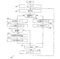
図8は、本開示の1実施例に従ってエネルギ発生システム500に対する集中型MPPTと分散型MPPTとの間の選択を行う方法800を例示している。方法800の実施例は単に例示的なものに過ぎない。方法800のその他の実施例を本開示の範囲を逸脱すること無しに実現することが可能である。
FIG. 8 illustrates a
方法800は、診断モジュール520がタイマーを設定することで開始する(ステップ802)。該タイマーは、繰り返しを基礎とする方法800の初期化をトリガーするために診断モジュール520によって使用することが可能である。診断モジュール520は、エネルギ発生システム500内のパネル等のエネルギ発生装置502を解析する(ステップ804)。例えば、幾つかの実施例の場合に、診断モジュール520は、各パネル502に対するパネルパワーPpanを計算し、次いで、図5に関連して上により詳細に説明した如く、Ppanのこれらの計算された値に基づいて多数のその他の値を決定することによって、パネル502を解析することが可能である。例えば、診断モジュール520は、計算されたPpan値の最大値及び最小値(夫々、Ppan,max及びPpan,min)を決定し、次いでパネル502が完全に又は部分的に陰が付けられていることの各パネル502に対する確率(ρ)を計算するためにこれらの最大値及び最小値を使用することが可能である。診断モジュール520は、又、計算された確率の最大値(ρmax)を決定することも可能である。
The
パネル502を解析した後に(ステップ804)、診断モジュール520は準理想的条件下で動作する(ステップ806)。例えば、幾つかの実施例の場合に、診断モジュール520は、パネル502が陰が付けられていることの計算された確率の最大値(ρmax)を予め定めたDMPPTスレッシュホールド(ρDMPPT)と比較することが可能である。ρmaxがρDMPPT未満である場合には、パネル502の最大出力パワー及び最小出力パワーは互いに十分に近いものであって、パネル502間のミスマッチの確率は極めて小さいものと考えることが可能であり、且つシステム500は準理想的条件下で動作しているものと考えることが可能である。同様に、ρmaxがρDMPPT未満で無い場合には、パネル502の最大出力パワー及び最小出力パワーは互いに十分に離れており、パネル502間のミスマッチの確率は極めて低いものと考えることは出来ず、システム500は準理想的条件下で動作していないものと考えることが可能である。
After analyzing panel 502 (step 804),
システム500が準理想的条件下で動作していないものと診断モジュール520が判別する場合には(ステップ806)、制御モジュール525は局所的制御器508をイネーブルさせ(ステップ808)且つグローバル制御器540をディスエーブルさせ(ステップ810)、それによりシステム500をDMPPTモードとさせる。従って、この状態においては、局所的制御器508は各個別的なパネル502に対してMPPTを実施する。
If the
DMPPTモードはパネル502間の比較的小さなミスマッチの場合でも使用されるので、診断モジュール520は、陰が付けられたパネル502の確率が非常に低いものであると考えられるものではないが尚且つ低いものであると考えられる場合であっても、システム500が準理想的条件下で動作しているものではないことを判別することが可能である。従って、DMPPTモードに入った後に、診断モジュール520は、陰が付けられたパネル502の確率が高いか否かを判別する(ステップ812)。例えば、診断モジュール520は、パネル502が陰が付けられていることの最大確率(ρmax)を予め定めた診断スレッシュホールド(ρdiag)と比較することが可能である。ρmaxがρdiagよりも大きい場合には、パネル502の最大出力パワー及び最小出力パワーは十分に離れており、パネル502間のミスマッチの確率は比較的高いものであり、従って少なくとも1個の陰が付けられたパネル502の確率が高いものと考えることが可能である。
Since the DMPPT mode is used even in the case of a relatively small mismatch between panels 502, the
陰が付けられたパネル502の確率が高い場合には(ステップ812)、診断モジュール520は全ての潜在的に陰が付けられている可能性のあるパネル502に対してフル特性スキャンを実施する(ステップ814)。例えば、診断モジュール520は、各パネル502に対して、パネル501が陰が付けられている確立(ρ)を診断スレッシュホールド(ρdiag)と比較することによって潜在的に陰が付けられている可能性のあるパネル502を識別することが可能である。特定のパネル502に対するρがρdiagよりも一層大きい場合には、その特定のパネル502の出力パワーはシステム500におけるパネル502によって与えられる最大出力パワーから十分にかなり離れており、その特定のパネル502が少なくとも部分的に陰が付けられている確立は比較的高い。
If the probability of shaded panel 502 is high (step 812),
フル特性スキャンを実施する場合に、診断モジュール520は、中央アレイ制御器510によって与えられるタイミングに基いて各潜在的に陰が付けられている可能性のあるパネル502に対する電圧対パワー特性のスキャンを個別的に実施することが可能である。この様に、変換ステージ512は該スキャン期間中に継続して通常通り動作することが可能である。
When performing a full characteristic scan, the
フル特性スキャンを実施している過程期間中に、いずれかのパネル502が過少実施である(即ち、MPP725のような実際のMPPの代わりに、局所的MPP720のような局所的最大パワー点(MPP)において動作している)ことを診断モジュール520が判別する場合には、制御モジュール525はこれらの過少実施状態のパネル502に対して補正を行なうことが可能である(ステップ816)。
During the process of performing a full characteristic scan, either panel 502 is under-performing (ie, instead of an actual MPP such as
この点において、又は陰が付けられているパネル502の高い確率が存在しない場合には(ステップ812)、診断モジュール520はタイマーが時間切れとなっているか否か(ステップ818)、即ち方法800が再度初期化されるべきであるか否か、を判別する。タイマーが時間切れである場合には(ステップ818)、診断モジュール520はタイマーをリセットし(ステップ820)且つ再度パネル502の解析を開始する(ステップ804)。
At this point, or if there is no high probability of shaded panel 502 (step 812),
システム500が準理想的条件下で動作していることを診断モジュール520が判別する場合には(ステップ806)、制御モジュール525は局所的制御器508をディスエーブルさせ(ステップ822)且つグローバル制御器540をイネーブルさせ(ステップ824)、それによりシステム500をCMPPTモードとさせる。従って、この状態において、グローバル制御器540は全システム500に対してMPPTを実施する。
If the
この点において、又、診断モジュール520は、タイマーが時間切れしたか否か、即ち方法800が再度初期化されるべきか否か、を判別する(ステップ818)。タイマーが時間切れであると(ステップ818)、診断モジュール520はタイマーをリセットし(ステップ820)且つ再度パネル502の解析を開始する(ステップ804)。
At this point, the
図8は集中型MPPTと分散型MPPTとの間の選択をする方法800の1例を例示しているが、この方法800に対して種々の変更を行なうことが可能である。例えば、方法800を光電システムを参照して説明しているが、方法800は、ウインドタービンシステム、燃料電池システム等のその他のエネルギ発生システム500に対して実現することが可能である。更に、方法800を図5のシステムを参照して説明しているが、方法800は本開示の範囲を逸脱すること無しに任意の適宜に構成されたエネルギ発生システムにおいて実現することが可能である。更に、一連のステップとして示してあるが、方法800におけるステップは、オーバーラップするか、並列に発生するか、複数回発生するか、又は異なる順番で発生することが可能である。
Although FIG. 8 illustrates one example of a
図9は、本開示の1実施例に従うエネルギ発生システムにおける局所的変換器904用の局所的制御器908を活性化且つ脱活性化させるシステム900を例示している。システム900は、光電パネル902として呼称されるエネルギ発生装置902と、局所的変換器904とを有している。局所的変換器904は、パワーステージ906と、局所的制御器908と、アクチベーター即ち活性化器910とを有している。
FIG. 9 illustrates a
局所的変換器904は、図1の局所的変換器104の内の一つ、図2又は3の局所的変換器204、及び/又は図5の局所的変換器504の内の一つを表すことが可能であるが、局所的変換器904は、本開示の範囲を逸脱すること無しに任意の適宜に構成されたエネルギ発生システムにおいて実現することが可能であることが理解される。従って、システム900は他の同様のシステム900へ直列的及び/又は並列的に結合されてエネルギ発生アレイを形成することが可能である。
The local converter 904 represents one of the local converters 104 of FIG. 1, the
例示した実施例の場合、アクチベーター910がパネル902と局所的制御器908との間に結合されている。幾つかの実施例の場合に、アクチベーター910は、パネル902の出力電圧に基づいて局所的制御器908を活性化させ且つ脱活性化させることが可能である。パネル902の出力電圧が低すぎる場合には、アクチベーター910は、基本的にゼロである供給電圧を局所的制御器908へ供給することが可能であり、それにより局所的制御器908をシャットオフさせる。パネル902の出力電圧が一層高い場合には、アクチベーター910は、局所的制御器908が動作可能状態となるべくゼロではない供給電圧を局所的制御器908へ供給することが可能である。
In the illustrated embodiment,
アクチベーター910は、局所的制御器908へ供給電圧を供給する以外の任意の適宜の態様で局所的制御器908を活性化させ且つ脱活性化させることが可能である。例えば、一つの代替例の場合に、アクチベーター910は、局所的制御器908を活性化させ且つ脱活性化させるために局所的制御器908の1個又はそれ以上のピンをセットさせることが可能である。別の代替例の場合には、アクチベーター910は、局所的制御器908を活性化させるために局所的制御器908内の第1レジスタへ第1所定値を書き込み、且つ局所的制御器908を脱活性化させるために局所的制御器908内の該第1レジスタ又は第2レジスタのいずれかに第2所定値(これは、特定の実現例に基づいて、第1所定値と同じもの又は異なるものとすることが可能である)を書き込むことが可能である。
The
従って、システム900は、バッテリ又は外部電源を使用すること無しに、局所的変換器904の自立的動作を与えている。太陽放射照度が十分に高い場合には、出力パネル電圧Vpanは、アクチベーター910をしてゼロではない供給電圧Vccの発生を開始させるレベルへ増加する。この点において、局所的制御器908及び/又は中央アレイ制御器(図9においては不図示)は、レジスタの初期化、パネル902間の予備的電圧比較、アナログ・デジタル変換器キャリブレーション、クロック同期又はインターリーブ、パワーステージ906の同期的活性化、等の活性化手順を実施することを開始することが可能である。同様に、システム900を脱活性化させる前に、スタンドアローン適用例の場合におけるバックアップユニットとの同期、パワーステージ906の同期的脱活性化、等の脱活性化手順を実施することが可能である。これらの脱活性化手順期間中に、アクチベーター910はそれ自身は活性化されたままとなることが可能である。
Thus, the
更に、幾つかの実施例の場合に、アクチベーター910は、局所的制御器904に対して過剰パワー保護を与えることが可能である。図3に関連して上に説明した如く、局所的制御器208の一部であるMPPT制御ブロック304は過剰パワー保護を与えることが可能である。然しながら、アクチベーター910を含むシステムに対する代替例として、アクチベーター910はその代わりにこの保護を与えることが可能である。従って、この代替例の場合には、出力電流が低すぎるほど低下すると、アクチベーター910は、パネル電圧Vpanがほぼ出力電圧Voutに等しいように局所的制御器908のMPPT機能性をスイッチオフさせることが可能である。
Further, in some embodiments,
図10は本開示の1実施例に基づくシステム900に対する時間に関しての装置電圧変化の1例を例示しているグラフ920である。光電パネル902の場合には、太陽放射照度レベルがアクチベーター910に対する電圧活性化レベル(Vt−on)周りに振動する状態において、電圧脱活性化レベル(Vt−off)と同じ電圧活性化レベルを使用することは、システム900の不所望の複数の活性化及び脱活性化を発生させることとなる。従って、グラフ920に示されているように、このことを防止するために、一層低い電圧脱活性化レベルを使用することが可能である。この一層低い電圧脱活性化レベルを使用することによって、システム900は、パネル電圧が電圧活性化レベルよりも幾分一層低いレベルへ降下するように太陽放射照度レベルが十分に減少するまで、一貫性をもって活性化されたまま留まることが可能である。その結果、頻繁な活性化及び脱活性化が回避され、システム900に対してノイズ免疫性を与えている。
FIG. 10 is a
幾つかの実施例の場合に、パネル電圧が電圧活性化レベルを超えて局所的制御器908の活性化となった後に、局所的制御器908は、パネル電圧が電圧脱活性化レベルよりも一層低いレベルへ継続して降下する場合に一層迅速に脱活性化させることが可能であるために、パネル電圧が電圧脱活性化レベルより下側に降下する場合に、脱活性化手順を開始することが可能である。更に、幾つかの実施例の場合に、局所的制御器908は、特定の状態に対して電圧脱活性化レベルに到達する前に、アクチベーター910、従ってそれ自身をシャットオフさせることが可能である。
In some embodiments, after the panel voltage exceeds the voltage activation level and the
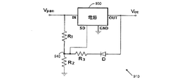
図11は、本開示の1実施例に従うアクチベーター910を例示している。この実施例の場合、アクチベーター910は、電源930と、複数個の抵抗R1,R2,R3と、ダイオードDとを有している。抵抗R1及びR2は、電源930の入力ノード(IN)と接地との間に直列に結合されている。該ダイオード及び抵抗R3は、電源930の出力ノード(OUT)と抵抗R1及びR2が共に結合されているノード940との間に直列に結合されている。更に、電源930のシャットダウンノード(SD)もノード940に結合されている。
FIG. 11 illustrates an
電源930は、その入力ノードにおいてパネル電圧Vpanを受け取り且つその出力ノードにおいて局所的制御器908用の供給電圧Vccを発生することが可能である。電源930のシャットダウンノードは、電源930の制御回路によって決定されるように該シャットダウンノードにおける電圧レベルが特定した電圧V0を超える場合に、電源930の動作をイネーブルさせ、且つ該シャットダウンノードにおける電圧レベルが該特定した電圧V0より下側に降下する場合に、電源930の動作をディスエーブルさせる。
The
電源930がターンオフされると、該ダイオードは非導通状態であり、且つ該シャットダウンノードにおける電圧は次式によって与えられる。
When
![]()
![]()
電圧VSD,t−onが値V0を超えると、該ダイオードは導通状態を開始し且つ該シャットダウンノードにおける電圧は以下の如くになる。 When the voltage V SD, t-on exceeds the value V 0 , the diode begins to conduct and the voltage at the shutdown node is:
![]()
![]()
尚、Vdはダイオード電圧降下であり、且つ Where V d is the diode voltage drop, and
![]()
![]()
である。電圧VSD,t−offがV0より下側に降下すると、電源930はターンオフされる。従って、ターンオン及びターンオフ電圧スレッシュホールドは、抵抗R1,R2,R3によって与えられる抵抗値に基づいて決定される。
It is. When the voltage V SD, t-off drops below V 0 , the
図12は、本開示の1実施例に従って局所的変換器904を活性化及び脱活性化させる方法1200を例示している。方法1200の実施例は、単に例示的なものであるに過ぎない。方法1200のその他の実施例を本開示の範囲を逸脱すること無しに実現することが可能である。
FIG. 12 illustrates a
方法1200は、開回路条件で動作しているエネルギ発生装置、即ちパネル、902で開始する(ステップ1202)。この条件において、アクチベーター910は局所的制御器908を活性化させていない。何故ならば、パネル902によって出力されるパネル電圧が低すぎるからである。アクチベーター910は、電圧活性化レベル(Vt−on)を超えるまで、このパネル電圧(Vpan)をモニターする(ステップ1204)。
The
パネル電圧が電圧活性化レベルを超えたことをアクチベーター910が判別すると(ステップ1204)、アクチベーター910は局所的制御器908をターンオンさせることによって局所的変換器904の活性化を開始する(ステップ1206)。例えば、アクチベーター910は、局所的制御器908に対してゼロではない供給電圧Vccを発生することによって局所的変換器904の活性化を開始することが可能である。その他の実施例の場合に、アクチベーター904は、局所的制御器908の1個又はそれ以上のピンをセットすることによって、又は局所的制御器908内の第1レジスタへ第1所定値を書き込むことによって局所的変換器904の活性化を開始することが可能である。局所的制御器908及び/又は中央アレイ制御器は、次いで、局所的変換器904に対する活性化手順を実施する(ステップ1208)。例えば、該活性化手順は、レジスタの初期化、パネル902間の予備的電圧比較、アナログ・デジタル変換器キャリブレーション、クロック同期又はインターリーブ、パワーステージ906等を含む複数のパネルからなるストリングの同期的活性化を含むことが可能である。
When activator 910 determines that the panel voltage has exceeded the voltage activation level (step 1204),
局所的制御器908は、該ストリング内の他のパワーステージ906が動作状態となるまで(ステップ1212)、所定の変換比でパワーステージ906を動作させる(ステップ1210)。該ストリング内のパネル902の各々が動作状態にあるパワーステージ906を持つと(ステップ1212)、局所的制御器908は、パネル電流(Ipan)を活性化電流レベル(Imin)と比較する(ステップ1214)。パネル電流が活性化電流レベルよりも一層大きい場合には(ステップ1214)、局所的制御器908が通常の動作を開始する(ステップ1216)。従って、局所的制御器908はパワーステージ906に対してMPPTの実施を開始する。
The
この様に、エネルギ発生システムにおける全ての局所的制御器908の活性化は自動的に同期させることが可能である。更に、光電システムにおける複数のパネル902からなるサブセットのみがアクチベーター910による活性化となるのに十分に高い電圧を発生するに過ぎない場合には、スイッチ314等の単一方向スイッチをパワーステージ906の各々に包含させて、残りのパネル902が動作されることを許容することが可能である。
In this way, the activation of all
局所的制御器908は、継続してパネル電流を活性化電流レベルと比較する(ステップ1218)。パネル電流が活性化電流レベル未満である場合には(ステップ1218)、局所的制御器908は脱活性化タイマーをセットする(ステップ1220)。局所的制御器908は、次いで、所定の変換比でパワーステージ906を動作することへ復帰する(ステップ1222)。次いで、局所的制御器908及び/又は中央アレイ制御器が局所的変換器904に対する脱活性化手順を実施する(ステップ1224)。例えば、該脱活性化手順は、スタンドアローン適用例の場合におけるバックアップユニットとの同期、パワーステージ906の同期的脱活性化等を含むことが可能である。
The
次いで、局所的制御器908は、脱活性化タイマーが時間切れとなったか否かを判別する(ステップ1226)。このことは、パネル電流が活性化電流レベルの上方へ増加することを許容する。従って、局所的制御器908は、脱活性化の準備をするが、脱活性化が実際に実施されるべきであることを確保するために待機する。
The
従って、脱活性化タイマーが時間切れとならない限り(ステップ1226)、局所的制御器908はパネル電流を活性化電流レベルと比較する(ステップ1228)。パネル電流が継続して活性化電流レベル未満に留まる場合には(ステップ1228)、局所的制御器908は継続して脱活性化タイマーの時間切れを待機する(ステップ1226)。脱活性化タイマーの時間切れ(ステップ1226)の前にパネル電流が活性化電流レベルより一層大きくなると(ステップ1228)、局所的制御器908は、再度、パワーステージ906に対してMPPTを実施することによって通常に動作する(ステップ1216)。
Thus, as long as the deactivation timer does not expire (step 1226), the
然しながら、パネル電流が活性化電流レベル未満である間(ステップ1228)に脱活性化タイマーが時間切れとなると(ステップ1226)、局所的制御器908はパワーステージ906及び局所的制御器908をターンオフし、且つパネル902は、再度、開回路条件で動作される(ステップ1230)。幾つかの実施例の場合に、アクチベーター910は、局所的制御器908に対してゼロの供給電圧Vccを発生することによって、局所的変換器904の脱活性化を完了する場合がある。その他の実施例の場合に、アクチベーター910は、局所的制御器908の1個又はそれ以上のピンをセットすることによって、又は局所的制御器908内の第1レジスタ又は第2レジスタのいずれかに第2所定値を書き込むことによって、局所的変換器904の脱活性化を完了する場合がある。この点において、アクチベーター910は、再度、電圧活性化レベルを超えるまで(ステップ1204)パネル電圧をモニタし、活性化プロセスを最初期化させる。
However, if the deactivation timer expires (step 1226) while the panel current is below the activation current level (step 1228), the
図12は局所的変換器904を活性化させ且つ脱活性化させるための方法1200の1例を例示しているが、この方法1200に対して種々の変形を行うことが可能である。例えば、方法1200は光電パネルを参照して説明しているが、方法1200は、ウインドタービン、燃料電池等のその他のエネルギ発生装置902に対して実現することが可能である。更に、方法1200を図9の局所的制御器908及びアクチベーター910を参照して説明しているが、局所的制御器908及びアクチベーター910は本開示の範囲を逸脱すること無しに任意の適宜に構成されたエネルギ発生システムにおいて実現することが可能であることが理解される。又、一連のステップとして示してあるが、方法1200におけるステップは、オーバーラップすること、並列的に発生すること、複数回発生すること、又は異なる順番で発生することが可能である。
Although FIG. 12 illustrates one example of a
上の説明は特定の実施例を参照しているが、説明したコンポーネント、システム及び方法の幾つかは、サブセル、単一セル、パネル(即ち、セルアレイ)、パネルアレイ、及び/又は複数のパネルアレイからなるシステムに対して適用することが可能であることが理解される。例えば、上述した局所的変換器は各々1個のパネルと関連しているものであるが、1個のパネル内の各セルに対しての、又は複数のパネルからなる各ストリングに対しての、局所的変換器と共に、同様にシステムを実現することが可能である。更に、説明したコンポーネント、システム及び方法の幾つかは、ウインドタービン、燃料電池等の光電装置以外のエネルギ発生装置へ適用することが可能である。 Although the above description refers to particular embodiments, some of the components, systems, and methods described are subcells, single cells, panels (ie, cell arrays), panel arrays, and / or multiple panel arrays. It is understood that the present invention can be applied to a system consisting of For example, the local transducers described above are each associated with one panel, but for each cell in a panel or for each string of panels. It is possible to implement a system with a local transducer as well. Furthermore, some of the components, systems and methods described can be applied to energy generating devices other than optoelectronic devices such as wind turbines and fuel cells.
この特許文書において使用されている或る単語及び用語の定義を説明しておくことが有益的である。「結合」という用語及びその派生語は、2個又はそれ以上のコンポーネント間のいかなる直接的又は間接的な通信を意味しており、これらのコンポーネントが互いに物理的に接触しているか否かを問うものではない。「送信」、「受信」及び「通信する」という用語及びそれらの派生語は、直接的な及び間接的な両方の通信を包含している。「含む」及び「有する」という用語及びそれらの派生語は、制限無しでの包含することを意味している。「又は」という用語は包括的であり、及び/又はの意味である。「各」という用語は識別された複数の項目からなる少なくともサブセット(副組)の内のどれもこれもである。「関連する」及び「それと関連する」という用語及びそれらの派生語は、包含すること、その中に包含されていること、それと相互接続していること、含むこと、その中に含まれること、それへ又はそれと接続すること、それへ又はそれと結合すること、それと通信可能であること、それと共同すること、インターリーブすること、並置すること、それに近接していること、それへ又はそれと束縛されていること、持っていること、その特性を持っていること、等を意味する場合がある。 It is useful to explain the definitions of certain words and terms used in this patent document. The term “coupled” and its derivatives means any direct or indirect communication between two or more components and asks whether these components are in physical contact with each other. It is not a thing. The terms “transmit”, “receive” and “communicate” and their derivatives encompass both direct and indirect communication. The terms “including” and “having” and their derivatives are meant to include without limitation. The term “or” is inclusive, meaning and / or. The term “each” is any of at least a subset of a plurality of identified items. The terms “related” and “related to” and their derivatives are included, included in, interconnected with, included in, included in, Connected to, connected to, connected to, coupled to, communicable with, collaborated with, interleaved, juxtaposed, close to it, bound to it or to it May mean having, having, or having that characteristic.
本開示を或る実施例及び通常関連する方法について説明したが、これらの実施例及び方法の変更及び置換は当業者に自明である。従って、例示的実施例の上の説明は本開示を定義付けるか又は拘束するものではない。以下の特許請求の範囲によって定義されるように、本開示の精神及び範囲を逸脱すること無しにその他の変化、置換、変形も可能である。 While this disclosure has been described with reference to certain embodiments and commonly associated methods, variations and substitutions of these embodiments and methods will be apparent to those skilled in the art. Accordingly, the above description of example embodiments does not define or constrain this disclosure. Other changes, substitutions, and modifications are possible without departing from the spirit and scope of the present disclosure, as defined by the following claims.
Claims (30)
該エネルギ発生装置が準理想的条件下で動作しているか否かを判別し、
該エネルギ発生装置が準理想的条件下で動作している場合には該エネルギ発生システムを集中型最大パワーポイントトラッキング(CMPPT)とさせ、
該エネルギ発生装置が準理想的条件下で動作していない場合には該エネルギ発生システムを分散型最大パワーポイントトラッキング(DMPPT)とさせる、
ことを包含している方法。 Each local transducer has a local controller for the corresponding energy generator, and each energy generator comprises a plurality of energy generators coupled to a corresponding local transducer. In a method for selecting between centralized and distributed maximum power point tracking in an energy generation system,
Determining whether the energy generator is operating under sub-ideal conditions;
If the energy generating device is operating under sub-ideal conditions, the energy generating system is centralized maximum power point tracking (CMPPT);
If the energy generating device is not operating under sub-ideal conditions, the energy generating system is distributed maximum power point tracking (DMPPT);
The method that encompasses that.
少なくとも1個の陰が付けられている可能性のあるエネルギ発生装置を識別し、
各識別された陰が付けられている可能性のあるエネルギ発生装置に対してフル特性スキャンを実施する、
ことを包含している方法。 The method of claim 4, further comprising determining that the probability that at least one of the energy generating devices is shaded is above the predetermined threshold.
Identify at least one shaded energy generator,
Perform a full characteristic scan for each identified shaded energy generator;
The method that encompasses that.
該フル特性スキャンに基づいて少なくとも1個の過少性能エネルギ発生装置を識別し、
各識別された過少性能エネルギ発生装置に対する補正を与える、
ことを包含している方法。 In claim 5, further:
Identifying at least one underperformance energy generator based on the full characteristic scan;
Providing a correction for each identified underperformance energy generator;
The method that encompasses that.
各エネルギ発生装置に対して、該エネルギ発生装置の各々と関連する出力パワー値に基づいて該エネルギ発生装置が陰が付けられていることの確率を計算し、
該計算した確率の中の最大値を識別し、
該計算した確率の中の該最大値をDMPPTスレッシュホールドと比較し、
該計算した確率の中の該最大値がDMPPTスレッシュホールド未満である場合には、該エネルギ発生装置が準理想的条件下で動作していることを判別する、
ことを包含している方法。 In claim 1, when determining whether the energy generating device is operating under quasi-ideal conditions,
For each energy generator, calculate the probability that the energy generator is shaded based on the output power value associated with each of the energy generators;
Identifying the maximum of the calculated probabilities;
Comparing the maximum of the calculated probabilities with the DMPPT threshold;
If the maximum of the calculated probabilities is less than the DMPPT threshold, determine that the energy generator is operating under sub-ideal conditions;
The method that encompasses that.
該エネルギ発生装置の各々に対して出力パワー値を計算し、
各エネルギ発生装置に対して、該エネルギ発生装置に対する出力パワー値に基づいて該エネルギ発生装置が陰が付けられていることの確率を計算し、
該計算した確率の中の最大値を識別し、
該計算した確率の中の該最大値を分散型最大パワーポイントトラッキング(DMPPT)スレッシュホールドと比較し、
該計算した確率の中の該最大値がDMPPTスレッシュホールド未満である場合には該エネルギ発生システムを集中型最大パワーポイントトラッキング(CMPPT)モードとさせ、
該計算した確率の中の該最大値がDMPPTスレッシュホールド以上である場合には該エネルギ発生システムをDMPPTモードとさせる、
ことを包含している方法。 Each local transducer has a local controller for the corresponding energy generator, and each energy generator comprises a plurality of energy generators coupled to a corresponding local transducer. In a method for selecting between centralized and distributed maximum power point tracking in an energy generation system,
Calculating an output power value for each of the energy generators;
For each energy generator, calculate the probability that the energy generator is shaded based on the output power value for the energy generator;
Identifying the maximum of the calculated probabilities;
Comparing the maximum of the calculated probabilities with a distributed maximum power point tracking (DMPPT) threshold;
If the maximum of the calculated probabilities is less than a DMPPT threshold, place the energy generating system in a centralized maximum power point tracking (CMPPT) mode;
If the maximum of the calculated probabilities is greater than or equal to the DMPPT threshold, the energy generating system is in DMPPT mode;
The method that encompasses that.
該エネルギ発生装置が準理想的条件下で動作しているか否かを判別することが可能な診断モジュール、
該エネルギ発生装置が準理想的条件下で動作している場合には、該エネルギ発生システムを集中型最大パワーポイントトラッキング(CMPPT)モードとさせ、且つ、該エネルギ発生装置が準理想的条件下で動作していない場合には、該エネルギ発生システムを分散型最大パワーポイントトラッキング(DMPPT)モードとさせることが可能な制御モジュール、
を有している中央アレイ制御器。 Each local transducer has a local controller for the corresponding energy generator, and each energy generator comprises a plurality of energy generators coupled to a corresponding local transducer. In a central array controller that can choose between centralized and decentralized maximum power point tracking for energy generation systems,
A diagnostic module capable of determining whether the energy generator is operating under sub-ideal conditions;
When the energy generator is operating under sub-ideal conditions, the energy generation system is in a centralized maximum power point tracking (CMPPT) mode and the energy generator is operating under sub-ideal conditions If not, a control module capable of causing the energy generation system to be in a distributed maximum power point tracking (DMPPT) mode;
Having a central array controller.
該エネルギ発生装置に対する装置電流を活性化電流レベルと比較し、
該装置電流が該活性化電流レベルより下側に降下する場合に該局所的変換器を自動的に脱活性化させる、
ことを包含している方法。 A method of deactivating a local converter for one of a plurality of energy generating devices in an energy generating array, the local converter comprising a power stage and a local controller.
Comparing the device current for the energy generator to the activation current level;
Automatically deactivating the local transducer when the device current falls below the activation current level;
The method that encompasses that.
特定した時間期間に対して該装置電流をモニターし、
該特定した時間期間に対して該装置電流が該活性化電流レベルの下側に留まる場合に、該局所的変換器の脱活性化を完了する、
ことを包含している方法。 In claim 24 , when automatically deactivating the local transducer,
Monitor the device current for a specified time period;
Complete deactivation of the local converter if the device current remains below the activation current level for the specified time period;
The method that encompasses that.
Applications Claiming Priority (5)
| Application Number | Priority Date | Filing Date | Title |
|---|---|---|---|
| US12/152,478 | 2008-05-14 | ||
| US12/152,566 US7991511B2 (en) | 2008-05-14 | 2008-05-14 | Method and system for selecting between centralized and distributed maximum power point tracking in an energy generating system |
| US12/152,478 US9077206B2 (en) | 2008-05-14 | 2008-05-14 | Method and system for activating and deactivating an energy generating system |
| US12/152,566 | 2008-05-14 | ||
| PCT/US2009/044036 WO2009140551A2 (en) | 2008-05-14 | 2009-05-14 | Method and system for selecting between centralized and distributed maximum power point tracking in an energy generating system |
Publications (3)
| Publication Number | Publication Date |
|---|---|
| JP2011521363A JP2011521363A (en) | 2011-07-21 |
| JP2011521363A5 JP2011521363A5 (en) | 2012-07-05 |
| JP5526333B2 true JP5526333B2 (en) | 2014-06-18 |
Family
ID=41319349
Family Applications (1)
| Application Number | Title | Priority Date | Filing Date |
|---|---|---|---|
| JP2011509723A Active JP5526333B2 (en) | 2008-05-14 | 2009-05-14 | Method and system for selecting between centralized and distributed maximum power point tracking in an energy generation system |
Country Status (6)
| Country | Link |
|---|---|
| EP (1) | EP2291899A4 (en) |
| JP (1) | JP5526333B2 (en) |
| KR (1) | KR20110019742A (en) |
| CN (1) | CN102067437B (en) |
| TW (1) | TWI498705B (en) |
| WO (1) | WO2009140551A2 (en) |
Families Citing this family (55)
| Publication number | Priority date | Publication date | Assignee | Title |
|---|---|---|---|---|
| US11881814B2 (en) | 2005-12-05 | 2024-01-23 | Solaredge Technologies Ltd. | Testing of a photovoltaic panel |
| US10693415B2 (en) | 2007-12-05 | 2020-06-23 | Solaredge Technologies Ltd. | Testing of a photovoltaic panel |
| US11855231B2 (en) | 2006-12-06 | 2023-12-26 | Solaredge Technologies Ltd. | Distributed power harvesting systems using DC power sources |
| US8384243B2 (en) | 2007-12-04 | 2013-02-26 | Solaredge Technologies Ltd. | Distributed power harvesting systems using DC power sources |
| US11687112B2 (en) | 2006-12-06 | 2023-06-27 | Solaredge Technologies Ltd. | Distributed power harvesting systems using DC power sources |
| US8319483B2 (en) | 2007-08-06 | 2012-11-27 | Solaredge Technologies Ltd. | Digital average input current control in power converter |
| US11728768B2 (en) | 2006-12-06 | 2023-08-15 | Solaredge Technologies Ltd. | Pairing of components in a direct current distributed power generation system |
| US11888387B2 (en) | 2006-12-06 | 2024-01-30 | Solaredge Technologies Ltd. | Safety mechanisms, wake up and shutdown methods in distributed power installations |
| US8816535B2 (en) | 2007-10-10 | 2014-08-26 | Solaredge Technologies, Ltd. | System and method for protection during inverter shutdown in distributed power installations |
| US11735910B2 (en) | 2006-12-06 | 2023-08-22 | Solaredge Technologies Ltd. | Distributed power system using direct current power sources |
| US11309832B2 (en) | 2006-12-06 | 2022-04-19 | Solaredge Technologies Ltd. | Distributed power harvesting systems using DC power sources |
| US8963369B2 (en) | 2007-12-04 | 2015-02-24 | Solaredge Technologies Ltd. | Distributed power harvesting systems using DC power sources |
| US9088178B2 (en) | 2006-12-06 | 2015-07-21 | Solaredge Technologies Ltd | Distributed power harvesting systems using DC power sources |
| US8473250B2 (en) | 2006-12-06 | 2013-06-25 | Solaredge, Ltd. | Monitoring of distributed power harvesting systems using DC power sources |
| US8013472B2 (en) | 2006-12-06 | 2011-09-06 | Solaredge, Ltd. | Method for distributed power harvesting using DC power sources |
| US11569659B2 (en) | 2006-12-06 | 2023-01-31 | Solaredge Technologies Ltd. | Distributed power harvesting systems using DC power sources |
| US8319471B2 (en) | 2006-12-06 | 2012-11-27 | Solaredge, Ltd. | Battery power delivery module |
| US8947194B2 (en) | 2009-05-26 | 2015-02-03 | Solaredge Technologies Ltd. | Theft detection and prevention in a power generation system |
| EP3324505B1 (en) | 2007-10-15 | 2023-06-07 | Ampt, Llc | Systems for highly efficient solar power |
| US7919953B2 (en) | 2007-10-23 | 2011-04-05 | Ampt, Llc | Solar power capacitor alternative switch circuitry system for enhanced capacitor life |
| WO2009072076A2 (en) | 2007-12-05 | 2009-06-11 | Solaredge Technologies Ltd. | Current sensing on a mosfet |
| JP2011507465A (en) | 2007-12-05 | 2011-03-03 | ソラレッジ テクノロジーズ リミテッド | Safety mechanism, wake-up method and shutdown method in distributed power installation |
| US11264947B2 (en) | 2007-12-05 | 2022-03-01 | Solaredge Technologies Ltd. | Testing of a photovoltaic panel |
| EP3719949A1 (en) | 2008-05-05 | 2020-10-07 | Solaredge Technologies Ltd. | Direct current power combiner |
| WO2010120315A1 (en) | 2009-04-17 | 2010-10-21 | Ampt, Llc | Methods and apparatus for adaptive operation of solar power systems |
| US9466737B2 (en) | 2009-10-19 | 2016-10-11 | Ampt, Llc | Solar panel string converter topology |
| CN103181051A (en) * | 2010-02-16 | 2013-06-26 | 丹福斯日光变换器有限公司 | A method of operating a maximum power point tracker |
| WO2011142406A1 (en) * | 2010-05-12 | 2011-11-17 | オムロン株式会社 | Voltage conversion device, voltage conversion method, power adjusting device, power adjusting method, solar power generation system, and management device |
| CN102253682B (en) * | 2010-05-18 | 2013-07-24 | 沈阳工程学院 | Maximum power point tracking (MPPT) control method of photovoltaic battery |
| DE102010036966B4 (en) * | 2010-08-12 | 2013-02-28 | Sma Solar Technology Ag | Method for operating a photovoltaic generator at a maximum power operating point |
| US10673229B2 (en) | 2010-11-09 | 2020-06-02 | Solaredge Technologies Ltd. | Arc detection and prevention in a power generation system |
| US10673222B2 (en) | 2010-11-09 | 2020-06-02 | Solaredge Technologies Ltd. | Arc detection and prevention in a power generation system |
| GB2485527B (en) | 2010-11-09 | 2012-12-19 | Solaredge Technologies Ltd | Arc detection and prevention in a power generation system |
| US10230310B2 (en) | 2016-04-05 | 2019-03-12 | Solaredge Technologies Ltd | Safety switch for photovoltaic systems |
| GB2483317B (en) | 2011-01-12 | 2012-08-22 | Solaredge Technologies Ltd | Serially connected inverters |
| EP2684218B1 (en) * | 2011-03-09 | 2018-05-02 | Solantro Semiconductor Corp. | Self mapping photovoltaic array system |
| US8570005B2 (en) | 2011-09-12 | 2013-10-29 | Solaredge Technologies Ltd. | Direct current link circuit |
| CN103166239B (en) * | 2011-12-09 | 2015-07-08 | 上海康威特吉能源技术有限公司 | Centralized-distributed mixed novel energy power generation system and maximum power point tracking control method |
| GB2498365A (en) | 2012-01-11 | 2013-07-17 | Solaredge Technologies Ltd | Photovoltaic module |
| GB2498790A (en) | 2012-01-30 | 2013-07-31 | Solaredge Technologies Ltd | Maximising power in a photovoltaic distributed power system |
| US9853565B2 (en) | 2012-01-30 | 2017-12-26 | Solaredge Technologies Ltd. | Maximized power in a photovoltaic distributed power system |
| GB2498791A (en) | 2012-01-30 | 2013-07-31 | Solaredge Technologies Ltd | Photovoltaic panel circuitry |
| GB2499991A (en) | 2012-03-05 | 2013-09-11 | Solaredge Technologies Ltd | DC link circuit for photovoltaic array |
| CN103378602A (en) * | 2012-04-20 | 2013-10-30 | 上海康威特吉能源技术有限公司 | Distributed type tandem photovoltaic grid connected power generation system and current sampling correcting method |
| JP5988208B2 (en) * | 2012-09-26 | 2016-09-07 | パナソニックIpマネジメント株式会社 | Inverter |
| US20140103892A1 (en) * | 2012-10-16 | 2014-04-17 | Volterra Semiconductor Corporation | Scalable maximum power point tracking controllers and associated methods |
| US10333299B2 (en) | 2013-03-05 | 2019-06-25 | Abb Schweiz Ag | Power converter and methods for increasing power delivery of soft alternating current power source |
| US9548619B2 (en) | 2013-03-14 | 2017-01-17 | Solaredge Technologies Ltd. | Method and apparatus for storing and depleting energy |
| US9397497B2 (en) | 2013-03-15 | 2016-07-19 | Ampt, Llc | High efficiency interleaved solar power supply system |
| CN105324901B (en) * | 2013-06-26 | 2018-01-23 | 三菱电机株式会社 | Voltage monitoring control device and voltage monitoring control method |
| WO2016008093A1 (en) * | 2014-07-15 | 2016-01-21 | 阳光电源股份有限公司 | Centralized mppt exiting and switching method and application thereof |
| TWI514714B (en) * | 2014-12-09 | 2015-12-21 | Univ Nat Cheng Kung | Distributed solar power system and controlling method thereof |
| US11177663B2 (en) | 2016-04-05 | 2021-11-16 | Solaredge Technologies Ltd. | Chain of power devices |
| US11018623B2 (en) | 2016-04-05 | 2021-05-25 | Solaredge Technologies Ltd. | Safety switch for photovoltaic systems |
| US11843253B2 (en) * | 2020-10-06 | 2023-12-12 | Navia Energy Inc. | Controlled energy system |
Family Cites Families (9)
| Publication number | Priority date | Publication date | Assignee | Title |
|---|---|---|---|---|
| US5327071A (en) * | 1991-11-05 | 1994-07-05 | The United States Of America As Represented By The Administrator Of The National Aeronautics & Space Administration | Microprocessor control of multiple peak power tracking DC/DC converters for use with solar cell arrays |
| US7269036B2 (en) * | 2003-05-12 | 2007-09-11 | Siemens Vdo Automotive Corporation | Method and apparatus for adjusting wakeup time in electrical power converter systems and transformer isolation |
| CN100438259C (en) * | 2003-08-05 | 2008-11-26 | 松下电器产业株式会社 | Direct-current power supply and battery-powered electronic apparatus equipped with the power supply |
| JP2005151662A (en) * | 2003-11-13 | 2005-06-09 | Sharp Corp | Inverter device and distributed power supply system |
| WO2005076445A1 (en) * | 2004-01-09 | 2005-08-18 | Philips Intellectual Property & Standards Gmbh | Decentralized power generation system |
| CN1797892A (en) * | 2004-12-30 | 2006-07-05 | 中国科学院电工研究所 | Tracker for maximum power of light-volt electric-power production by solar energy, and control method |
| JP4776348B2 (en) * | 2005-11-11 | 2011-09-21 | シャープ株式会社 | Inverter device |
| TWI296457B (en) * | 2006-01-18 | 2008-05-01 | Univ Yuan Ze | High-performance power conditioner for solar photovoltaic system |
| US8751053B2 (en) * | 2006-10-19 | 2014-06-10 | Tigo Energy, Inc. | Method and system to provide a distributed local energy production system with high-voltage DC bus |
-
2009
- 2009-05-13 TW TW098115860A patent/TWI498705B/en active
- 2009-05-14 EP EP09747632.9A patent/EP2291899A4/en not_active Withdrawn
- 2009-05-14 CN CN200980123556.7A patent/CN102067437B/en active Active
- 2009-05-14 JP JP2011509723A patent/JP5526333B2/en active Active
- 2009-05-14 WO PCT/US2009/044036 patent/WO2009140551A2/en active Application Filing
- 2009-05-14 KR KR1020107028019A patent/KR20110019742A/en not_active Application Discontinuation
Also Published As
| Publication number | Publication date |
|---|---|
| EP2291899A4 (en) | 2015-03-04 |
| KR20110019742A (en) | 2011-02-28 |
| EP2291899A2 (en) | 2011-03-09 |
| TWI498705B (en) | 2015-09-01 |
| CN102067437B (en) | 2014-07-02 |
| WO2009140551A3 (en) | 2010-02-25 |
| CN102067437A (en) | 2011-05-18 |
| WO2009140551A2 (en) | 2009-11-19 |
| JP2011521363A (en) | 2011-07-21 |
| TW201009534A (en) | 2010-03-01 |
Similar Documents
| Publication | Publication Date | Title |
|---|---|---|
| JP5526333B2 (en) | Method and system for selecting between centralized and distributed maximum power point tracking in an energy generation system | |
| JP5361994B2 (en) | Method and system for providing a local transducer for providing maximum power point tracking in an energy generation system | |
| JP5357249B2 (en) | Method and system for providing maximum power point tracking in an energy generation system | |
| US7962249B1 (en) | Method and system for providing central control in an energy generating system | |
| US9077206B2 (en) | Method and system for activating and deactivating an energy generating system | |
| JP2011522313A (en) | System and method for incorporating local maximum power point tracking in an energy generation system with central maximum power point tracking | |
| US7991511B2 (en) | Method and system for selecting between centralized and distributed maximum power point tracking in an energy generating system | |
| US8279644B2 (en) | Method and system for providing maximum power point tracking in an energy generating system | |
| US8139382B2 (en) | System and method for integrating local maximum power point tracking into an energy generating system having centralized maximum power point tracking | |
| US8053929B2 (en) | Solar power array with maximized panel power extraction | |
| US20200144825A1 (en) | Power convertor, power generation system, and power generation control method | |
| EP3780314B1 (en) | Method and device for tracking maximum power point | |
| EP2896100A1 (en) | Method and apparatus for bidirectional power production in a power module | |
| KR20060044698A (en) | Method for partial shade compasation of pv | |
| US11081961B2 (en) | Power convertor, power generation system, and power generation control method | |
| Jerin | Direct control method applied for improved incremental conductance mppt using SEPIC converter | |
| US20140265590A1 (en) | Pre-regulator and pre-regulation methods for photovioltaic inverters |
Legal Events
| Date | Code | Title | Description |
|---|---|---|---|
| A521 | Request for written amendment filed |
Free format text: JAPANESE INTERMEDIATE CODE: A523 Effective date: 20120514 |
|
| A621 | Written request for application examination |
Free format text: JAPANESE INTERMEDIATE CODE: A621 Effective date: 20120514 |
|
| A131 | Notification of reasons for refusal |
Free format text: JAPANESE INTERMEDIATE CODE: A131 Effective date: 20130806 |
|
| A601 | Written request for extension of time |
Free format text: JAPANESE INTERMEDIATE CODE: A601 Effective date: 20131105 |
|
| A602 | Written permission of extension of time |
Free format text: JAPANESE INTERMEDIATE CODE: A602 Effective date: 20131112 |
|
| A601 | Written request for extension of time |
Free format text: JAPANESE INTERMEDIATE CODE: A601 Effective date: 20131204 |
|
| A602 | Written permission of extension of time |
Free format text: JAPANESE INTERMEDIATE CODE: A602 Effective date: 20131211 |
|
| A601 | Written request for extension of time |
Free format text: JAPANESE INTERMEDIATE CODE: A601 Effective date: 20131225 |
|
| A602 | Written permission of extension of time |
Free format text: JAPANESE INTERMEDIATE CODE: A602 Effective date: 20140108 |
|
| A521 | Request for written amendment filed |
Free format text: JAPANESE INTERMEDIATE CODE: A523 Effective date: 20140204 |
|
| TRDD | Decision of grant or rejection written | ||
| A01 | Written decision to grant a patent or to grant a registration (utility model) |
Free format text: JAPANESE INTERMEDIATE CODE: A01 Effective date: 20140304 |
|
| RD02 | Notification of acceptance of power of attorney |
Free format text: JAPANESE INTERMEDIATE CODE: A7422 Effective date: 20140313 |
|
| A61 | First payment of annual fees (during grant procedure) |
Free format text: JAPANESE INTERMEDIATE CODE: A61 Effective date: 20140314 |
|
| R150 | Certificate of patent or registration of utility model |
Ref document number: 5526333 Country of ref document: JP Free format text: JAPANESE INTERMEDIATE CODE: R150 |
|
| R250 | Receipt of annual fees |
Free format text: JAPANESE INTERMEDIATE CODE: R250 |
|
| R250 | Receipt of annual fees |
Free format text: JAPANESE INTERMEDIATE CODE: R250 |
|
| R250 | Receipt of annual fees |
Free format text: JAPANESE INTERMEDIATE CODE: R250 |
|
| R250 | Receipt of annual fees |
Free format text: JAPANESE INTERMEDIATE CODE: R250 |
|
| R250 | Receipt of annual fees |
Free format text: JAPANESE INTERMEDIATE CODE: R250 |
|
| R250 | Receipt of annual fees |
Free format text: JAPANESE INTERMEDIATE CODE: R250 |
|
| R250 | Receipt of annual fees |
Free format text: JAPANESE INTERMEDIATE CODE: R250 |