JP5526302B2 - Optical unit with light output pattern synthesized from multiple light sources - Google Patents
Optical unit with light output pattern synthesized from multiple light sources Download PDFInfo
- Publication number
- JP5526302B2 JP5526302B2 JP2011516893A JP2011516893A JP5526302B2 JP 5526302 B2 JP5526302 B2 JP 5526302B2 JP 2011516893 A JP2011516893 A JP 2011516893A JP 2011516893 A JP2011516893 A JP 2011516893A JP 5526302 B2 JP5526302 B2 JP 5526302B2
- Authority
- JP
- Japan
- Prior art keywords
- lamp assembly
- solid state
- light
- led
- output
- Prior art date
- Legal status (The legal status is an assumption and is not a legal conclusion. Google has not performed a legal analysis and makes no representation as to the accuracy of the status listed.)
- Expired - Fee Related
Links
Images


Classifications
-
- F—MECHANICAL ENGINEERING; LIGHTING; HEATING; WEAPONS; BLASTING
- F21—LIGHTING
- F21K—NON-ELECTRIC LIGHT SOURCES USING LUMINESCENCE; LIGHT SOURCES USING ELECTROCHEMILUMINESCENCE; LIGHT SOURCES USING CHARGES OF COMBUSTIBLE MATERIAL; LIGHT SOURCES USING SEMICONDUCTOR DEVICES AS LIGHT-GENERATING ELEMENTS; LIGHT SOURCES NOT OTHERWISE PROVIDED FOR
- F21K9/00—Light sources using semiconductor devices as light-generating elements, e.g. using light-emitting diodes [LED] or lasers
- F21K9/20—Light sources comprising attachment means
- F21K9/23—Retrofit light sources for lighting devices with a single fitting for each light source, e.g. for substitution of incandescent lamps with bayonet or threaded fittings
-
- F—MECHANICAL ENGINEERING; LIGHTING; HEATING; WEAPONS; BLASTING
- F21—LIGHTING
- F21K—NON-ELECTRIC LIGHT SOURCES USING LUMINESCENCE; LIGHT SOURCES USING ELECTROCHEMILUMINESCENCE; LIGHT SOURCES USING CHARGES OF COMBUSTIBLE MATERIAL; LIGHT SOURCES USING SEMICONDUCTOR DEVICES AS LIGHT-GENERATING ELEMENTS; LIGHT SOURCES NOT OTHERWISE PROVIDED FOR
- F21K9/00—Light sources using semiconductor devices as light-generating elements, e.g. using light-emitting diodes [LED] or lasers
- F21K9/60—Optical arrangements integrated in the light source, e.g. for improving the colour rendering index or the light extraction
-
- F—MECHANICAL ENGINEERING; LIGHTING; HEATING; WEAPONS; BLASTING
- F21—LIGHTING
- F21S—NON-PORTABLE LIGHTING DEVICES; SYSTEMS THEREOF; VEHICLE LIGHTING DEVICES SPECIALLY ADAPTED FOR VEHICLE EXTERIORS
- F21S8/00—Lighting devices intended for fixed installation
- F21S8/08—Lighting devices intended for fixed installation with a standard
-
- F—MECHANICAL ENGINEERING; LIGHTING; HEATING; WEAPONS; BLASTING
- F21—LIGHTING
- F21W—INDEXING SCHEME ASSOCIATED WITH SUBCLASSES F21K, F21L, F21S and F21V, RELATING TO USES OR APPLICATIONS OF LIGHTING DEVICES OR SYSTEMS
- F21W2131/00—Use or application of lighting devices or systems not provided for in codes F21W2102/00-F21W2121/00
- F21W2131/10—Outdoor lighting
- F21W2131/103—Outdoor lighting of streets or roads
-
- F—MECHANICAL ENGINEERING; LIGHTING; HEATING; WEAPONS; BLASTING
- F21—LIGHTING
- F21Y—INDEXING SCHEME ASSOCIATED WITH SUBCLASSES F21K, F21L, F21S and F21V, RELATING TO THE FORM OR THE KIND OF THE LIGHT SOURCES OR OF THE COLOUR OF THE LIGHT EMITTED
- F21Y2107/00—Light sources with three-dimensionally disposed light-generating elements
- F21Y2107/10—Light sources with three-dimensionally disposed light-generating elements on concave supports or substrates, e.g. on the inner side of bowl-shaped supports
-
- F—MECHANICAL ENGINEERING; LIGHTING; HEATING; WEAPONS; BLASTING
- F21—LIGHTING
- F21Y—INDEXING SCHEME ASSOCIATED WITH SUBCLASSES F21K, F21L, F21S and F21V, RELATING TO THE FORM OR THE KIND OF THE LIGHT SOURCES OR OF THE COLOUR OF THE LIGHT EMITTED
- F21Y2115/00—Light-generating elements of semiconductor light sources
- F21Y2115/10—Light-emitting diodes [LED]
Description
[0001]本出願は、2008年7月2日に出願した、参照によりその開示全体が本明細書に組み込まれている、「Light Unit With Light Output Pattern Synthesized From Multiple LightSources,」という名称の米国特許仮出願第61/077747号の優先権を主張するものである。 [0001] This application is a US patent entitled “Light Unit With Light Output Pattern Synthesized From Multiple LightSources,” filed on July 2, 2008, the entire disclosure of which is incorporated herein by reference. The priority of provisional application 61/0777747 is claimed.
[0002]本開示はLEDベース光ユニットに関し、より具体的には、少数のLEDエレメント及び少数の光学系を使用した、合成出力パターンを備えたLEDベース光ユニットに関する。 [0002] The present disclosure relates to LED-based light units, and more particularly to LED-based light units with a composite output pattern using a small number of LED elements and a small number of optical systems.
[0003]照明システムには、伝統的に、白熱光、蛍光光及び発光ダイオード(LED)をベースとする光を一般的に含む様々な異なるタイプの照明デバイスが使用されている。LEDをベースとする光には、特定の光又は照明システムのニーズに見合う十分な光を生成するために、通常、複数のダイオードエレメントが利用されている。常に高騰するエネルギーの価格をオフセットさせ、又、温室ガスの発生を有意に抑制するための手法の1つとして、LED照明は、この点に関して極めて有望である。1ワット当たり150ルーメンに接近しつつあり、又、寿命が50,000時間を超えるその有効性のため、LED及びLED技術に基づく照明製品は、潜在的に、住宅用及び商用の屋内及び屋外アプリケーションにおける照明市場に食い込む大きな可能性を秘めている。 [0003] Various different types of lighting devices are traditionally used in lighting systems, typically including light based on incandescent light, fluorescent light, and light emitting diodes (LEDs). For LED-based light, multiple diode elements are typically utilized to generate enough light to meet the needs of a particular light or lighting system. As one of the approaches to offset the constantly rising energy prices and significantly reduce greenhouse gas generation, LED lighting is very promising in this regard. Because of its effectiveness, approaching 150 lumens per watt and with a lifetime exceeding 50,000 hours, lighting products based on LEDs and LED technology are potentially residential and commercial indoor and outdoor applications. It has great potential to cut into the lighting market.
[0004]LEDをベースとする光は、例えば白熱源と比較すると、著しく有利な効率及び寿命を提供し、又、生成される廃熱がより少ない。例えば、完全な固体照明デバイスを製造したと仮定すると、白熱照明源の場合に必要なエネルギーと等価のエネルギーのわずかに1/20のエネルギーを使用するだけで同じレベルの輝度を達成することができる。LEDの場合、白熱光及びコンパクト蛍光などの多くの他の照明源より長い寿命が提供され、又、蛍光タイプの光に含まれている環境に有害な水銀は含まれていない。又、LEDをベースとする光によれば、瞬時オンの利点が提供され、又、オン−オフサイクルの反復によって劣化することはない。 [0004] LED-based light provides significantly advantageous efficiencies and lifetimes, for example, compared to incandescent sources, and produces less waste heat. For example, assuming that a complete solid state lighting device has been manufactured, the same level of brightness can be achieved using only 1/20 of the energy equivalent to that required for an incandescent lighting source. . LEDs provide a longer life than many other illumination sources, such as incandescent light and compact fluorescent light, and do not contain mercury that is harmful to the environment contained in fluorescent type light. Also, LED-based light provides the instant on advantage and does not degrade with repeated on-off cycles.
[0005]上で言及したように、LEDをベースとする光には、通常、光を生成するための複数のLEDエレメントが利用されている。LEDエレメントは、当分野でよく知られているように微小面光源であり、放射パターンを整形し、又、LEDの出力の反射を補助する関連光学系をしばしば備えている。LEDは、電子デバイス上の微小表示光としてしばしば使用されており、懐中電灯及び面照明などのより大きい電力アプリケーションがますます増加している。放出される光の色は、LEDの接合を形成するために使用される半導体材料の組成及び条件で決まり、赤外光、可視光及び紫外光を使用することができる。 [0005] As mentioned above, LED-based light typically utilizes a plurality of LED elements for generating light. LED elements are microsurface light sources, as is well known in the art, and often have associated optics that shape the radiation pattern and assist in reflecting the output of the LED. LEDs are often used as micro-display light on electronic devices, and increasingly larger power applications such as flashlights and surface lighting. The color of the emitted light depends on the composition and conditions of the semiconductor material used to form the LED junction, and infrared light, visible light and ultraviolet light can be used.
[0006]可視スペクトル内では、LEDは、所望の色が生成されるように製造することができる。LEDが面照明のために使用されるアプリケーションの場合、白色光出力であることが一般的には望ましい。高強度白色光LEDを製造するための2つの一般的な方法が存在している。1つの方法は、最初に3原色(赤、緑及び青)を放出する個々のLEDを製造し、次にこれらのすべての色を混合して白色光を生成することである。このような製品は、一般に多色白色LEDと呼ばれており、RGB LEDと呼ばれることもある。このような多色LEDには、通常、異なる色の配合及び拡散を制御するための複雑な電気光学設計が必要であり、又、この手法は、この業界ではこれまでのところ、白色LEDを大量生産するためにはほとんど使用されていない。原理的には、この機構は、白色光の生成においては比較的高い量子効率を有している。 [0006] Within the visible spectrum, LEDs can be manufactured to produce a desired color. For applications where LEDs are used for surface illumination, a white light output is generally desirable. There are two common methods for manufacturing high intensity white light LEDs. One method is to first produce individual LEDs that emit the three primary colors (red, green and blue) and then mix all these colors to produce white light. Such products are commonly referred to as multicolor white LEDs and are sometimes referred to as RGB LEDs. Such multi-color LEDs typically require complex electro-optic designs to control the blending and diffusion of different colors, and this approach has so far been a large amount of white LEDs in the industry. It is rarely used to produce. In principle, this mechanism has a relatively high quantum efficiency in the production of white light.
[0007]白色LED出力を生成する第2の方法は、InGaNでできた青色LEDなどの1つの色のLEDを製造し、そのLEDに異なる色の燐光体コーティング材をコーティングして白色光を生成することである。このようなLEDベース照明エレメントを製造するための一般的な方法の1つは、燐光体がコーティングされたエポキシの内側にInGaN青色LEDをカプセル封じすることである。一般的な黄色燐光体材料は、セリウムがドープされたイットリウムアルミニウムガーネット(Ce3+:YAG)である。元のLEDの色に応じて、異なる色の燐光体を使用することも可能である。このような技法を使用して製造されたLEDは、一般に燐光体ベース白色LEDと呼ばれている。製造コストは多色LEDより安価ではあるが、燐光体ベースLEDは、多色LEDと比較すると、より小さい量子効率を有している。又、燐光体ベースLEDは、燐光体に関連する劣化問題を抱えており、LEDの出力が時間と共に劣化する。燐光体ベース白色LEDは、製造が比較的より容易であるが、このようなLEDは、より短い波長の光子(例えば青色光子)がより長い波長の光子(例えば白色光子)に変換される場合に生じる損失であるストークスエネルギー損失によって影響される。したがって、このようなアプリケーションに使用される燐光体の量を少なくすることがしばしば望ましく、それによりこのエネルギー損失を小さくすることがしばしば望ましい。したがって、このように燐光体の量が少ないLEDエレメントを使用したLEDをベースとする白色光は、通常、観察者から見ると青色を有している。 [0007] A second method of producing white LED output is to produce a single color LED, such as a blue LED made of InGaN, and coat the LED with a different color phosphor coating material to produce white light. It is to be. One common method for manufacturing such LED-based lighting elements is to encapsulate an InGaN blue LED inside a phosphor-coated epoxy. A common yellow phosphor material is cerium-doped yttrium aluminum garnet (Ce3 +: YAG). Depending on the color of the original LED, it is also possible to use phosphors of different colors. LEDs manufactured using such techniques are commonly referred to as phosphor-based white LEDs. Although the manufacturing cost is cheaper than multicolor LEDs, phosphor-based LEDs have lower quantum efficiency compared to multicolor LEDs. Also, phosphor-based LEDs have a degradation problem associated with phosphors, and the output of the LED degrades over time. Phosphor-based white LEDs are relatively easier to manufacture, but such LEDs are used when shorter wavelength photons (eg, blue photons) are converted to longer wavelength photons (eg, white photons). It is affected by the Stokes energy loss, which is the loss that occurs. Therefore, it is often desirable to reduce the amount of phosphor used in such applications, thereby reducing this energy loss. Accordingly, white light based on LEDs using such LED elements with a low amount of phosphor usually has a blue color when viewed from the observer.
[0008]様々な他のタイプの固体照明エレメントを様々な照明アプリケーションに使用することも可能である。量子ドットは、例えば、固有の光特性を有する半導体ナノクリスタルである。量子ドットの発光色は、可視スペクトルから赤外スペクトルまで調整することができる。したがって量子ドットLEDは、ほぼすべての出力色を生成することができる。有機発光ダイオード(OLED)には、有機化合物である放出層材料が含まれている。半導体として機能させるためには、この有機放出材料は、共役π結合を有していなければならない。放出材料は、結晶相又は重合体中の微小有機分子であってもよい。重合体材料は可撓性であってもよく、このようなLEDは、PLED又はFLEDとして知られている。 [0008] Various other types of solid state lighting elements may be used for various lighting applications. A quantum dot is, for example, a semiconductor nanocrystal having unique optical characteristics. The emission color of the quantum dots can be adjusted from the visible spectrum to the infrared spectrum. Thus, quantum dot LEDs can generate almost any output color. Organic light emitting diodes (OLEDs) include emissive layer materials that are organic compounds. In order to function as a semiconductor, the organic emission material must have a conjugated π bond. The release material may be a small organic molecule in a crystalline phase or polymer. The polymeric material may be flexible and such LEDs are known as PLEDs or FLEDs.
[0009]本開示によれば、少数のLEDエレメントを使用して所望の照明特性を満足する出力照明パターンを生成するLEDベース光ユニットが提供される。本開示によれば、他の点光源と結合すると、LEDヘッドカウントを最少化し、且つ、追加ビームステアリング光学系を必要としない合成光出力が提供されるよう、所望の方向に導かれる多数の点光源が提供される。 [0009] According to the present disclosure, an LED-based light unit is provided that uses a small number of LED elements to generate an output illumination pattern that satisfies a desired illumination characteristic. In accordance with the present disclosure, a number of points that are directed in a desired direction to combine with other point light sources to provide a combined light output that minimizes LED head count and does not require additional beam steering optics. A light source is provided.
[0010]本開示の一態様によれば、ランプアセンブリであって、(a)複数の取付け面を有し、該複数の取付け面が、ランプアセンブリによって照明される面に実質的に平行の第1の平面に対して複数の異なる角度を有する面を備えるハウジングと、(b)個々の取付け面に取り付けられる少なくとも1つの固体光エレメントであって、複数の光エレメントからなる少なくとも1つのの各々が、第1の平面に対して直角をなしている第2の平面と交差し、且つ、ハウジングの中心線と交差する対応する個々の主軸に沿って光出力を提供し、複数の固体光エレメントの出力が結合して合成照明パターンを形成する、少なくとも1つの固体光エレメントとを備える、ランプアセンブリが提供される。一実施形態では、複数の固体光エレメントのうちの少なくとも1つは、関連する固体光エレメントによって生成される光を平行にする平行化コンポーネントを備えており、この平行化コンポーネントは、固体光エレメントによって出力光を5°以下のビーム角に平行化することができる。一実施形態では、固体照明エレメントによって提供される光が平行化され、それにより複数の固体照明エレメントの他の角強度と実質的に等価の角強度が提供される。様々な実施形態のランプアセンブリの照明パターンは、白熱ランプ又はガス放電ランプによって提供される一様性より優れた一様性を有している。いくつかの実施形態では、照明パターンは、ランプアセンブリに対して非対称である。 [0010] According to one aspect of the present disclosure, a lamp assembly includes: (a) a plurality of mounting surfaces, wherein the plurality of mounting surfaces are substantially parallel to a surface illuminated by the lamp assembly. A housing comprising surfaces having a plurality of different angles with respect to a plane, and (b) at least one solid state optical element attached to each mounting surface, each of at least one of the plurality of optical elements comprising Providing a light output along a corresponding individual major axis that intersects a second plane perpendicular to the first plane and intersects the center line of the housing; A lamp assembly is provided comprising at least one solid state light element whose outputs combine to form a composite illumination pattern. In one embodiment, at least one of the plurality of solid state optical elements comprises a collimating component that collimates the light generated by the associated solid state optical element, the collimating component being The output light can be collimated to a beam angle of 5 ° or less. In one embodiment, the light provided by the solid state lighting elements is collimated, thereby providing an angular intensity that is substantially equivalent to other angular intensities of the plurality of solid state lighting elements. The illumination patterns of the lamp assemblies of various embodiments have a uniformity that is superior to that provided by incandescent or gas discharge lamps. In some embodiments, the illumination pattern is asymmetric with respect to the lamp assembly.
[0011]一実施形態では、ランプアセンブリには、第1の複数の取付け面及び第2の複数の取付け面を備えた取付け面が含まれており、第1の複数の取付け面は、平均すると、第2の平面に対して第2の複数の取付け面より小さい角度を有している。他の実施形態では、第1の複数の取付け面に取り付けられる固体照明エレメントが、照明パターンの第1の領域のための照明を提供し、又、第2の複数の取付け面に取り付けられる固体照明エレメントが、照明パターンの第2の領域のための照明を提供する。さらに他の実施形態では、第1の領域を第2の領域より広くすることができ、或いはこれらの領域のサイズを同じにしてオフセットさせることができる。 [0011] In one embodiment, the lamp assembly includes a mounting surface comprising a first plurality of mounting surfaces and a second plurality of mounting surfaces, wherein the first plurality of mounting surfaces averages And an angle smaller than the second plurality of mounting surfaces with respect to the second plane. In other embodiments, a solid state lighting element attached to the first plurality of mounting surfaces provides illumination for the first region of the lighting pattern and is also attached to the second plurality of mounting surfaces. An element provides illumination for the second region of the illumination pattern. In still other embodiments, the first region can be wider than the second region, or the size of these regions can be the same and offset.
[0012]本開示の他の態様によれば、ランプアセンブリであって、(a)照明パターンを形成するように構成され、且つ、ランプアセンブリから該ランプアセンブリによって照明される面まで実質的に直角に延在する主軸を有するランプアセンブリに取り付けられる複数の固体光エレメントと、(b)主軸に対して複数の角度を有する取付け面であって、該取付け面に複数の固体光エレメントが取り付けられ、それらの各々が取付け面に対して直角の出力軸に沿って光出力を提供し、複数の固体光エレメントからなる少なくとも1つのの出力軸が、主軸を含んだ平面及びランプアセンブリの中心線と交差する、取付け面とを備える、ランプアセンブリが提供される。出力パターンは、ランプアセンブリの中心線に対して非対称にすることができる。一実施形態では、非対称出力パターンには、第1の照明領域及び第1の照明領域より小さい第2の照明領域が含まれている。他の実施形態では、非対称出力パターンには、第1の照明領域及び第1の照明領域の面積と実質的に同じ面積の第2の照明領域が含まれている。他の実施形態では、第1の照明領域は第2の照明領域からオフセットしている。いくつかの実施形態では、光エレメントが他の光エレメントに向かって取り付けられ、且つ、他の光エレメントに向かって導かれており、したがってランプアセンブリは、様々な「ダークスカイ」ゴールに応じることができるため、ランプアセンブリから放出されるアップライトが抑制される。 [0012] According to another aspect of the present disclosure, a lamp assembly is configured to (a) be configured to form an illumination pattern and substantially perpendicular from the lamp assembly to a surface illuminated by the lamp assembly. A plurality of solid state light elements attached to a lamp assembly having a main axis extending to, and (b) a mounting surface having a plurality of angles with respect to the main axis, wherein the plurality of solid state light elements are attached to the mounting surface, Each of them provides light output along an output axis perpendicular to the mounting surface, and at least one output axis comprising a plurality of solid state light elements intersects the plane containing the main axis and the centerline of the lamp assembly And a mounting surface is provided. The output pattern can be asymmetric with respect to the centerline of the lamp assembly. In one embodiment, the asymmetric output pattern includes a first illumination area and a second illumination area that is smaller than the first illumination area. In other embodiments, the asymmetric output pattern includes a first illumination region and a second illumination region having substantially the same area as the area of the first illumination region. In other embodiments, the first illumination area is offset from the second illumination area. In some embodiments, the optical elements are mounted towards and guided towards other optical elements, so that the lamp assembly can respond to various “dark sky” goals. As a result, upright emitted from the lamp assembly is suppressed.
[0013]本開示の他の態様によれば、ランプアセンブリであって、(a)ランプアセンブリから該ランプアセンブリによって照明される面まで実質的に直角に延在する主軸を有する、複数の取付け面を備えるハウジングと、(b)取付け面に取り付けられる複数の固体光エレメントと、(c)固体光エレメントからなる少なくとも1つのに取り付けられる、対応する個々の光エレメントからの出力光を平行にする複数の平行化コンポーネントと、(d)平行化コンポーネントからなる少なくとも1つのに取り付けられる複数の拡大光学系(spreading optics)であって、平行化コンポーネントからの出力光を、光エレメントによって照明される対象の光エレメントからの距離に基づいて選択されるビーム幅に拡大する、複数の拡大光学系とを備える、ランプアセンブリが提供される。 [0013] According to another aspect of the present disclosure, a lamp assembly comprising: (a) a plurality of mounting surfaces having a major axis extending substantially perpendicularly from the lamp assembly to a surface illuminated by the lamp assembly; A housing comprising: (b) a plurality of solid state optical elements attached to the mounting surface; and (c) a plurality of parallel output lights from corresponding individual light elements attached to at least one of the solid state optical elements. And (d) a plurality of spreading optics attached to at least one of the collimating components, wherein the output light from the collimating components is to be illuminated by the optical element Multiple expansions that expand to a selected beam width based on distance from the optical element And an optical system, the lamp assembly is provided.
[0014]本開示のさらに他の態様によれば、固体照明アセンブリから所望の照明パターンを生成するための方法であって、(a)複数の異なる固体光エレメントからの出力光をベクトルとしてモデル化するステップであって、個々のベクトルの方向が対応する個々の光エレメント出力の中央ローブのポインティングに基づいて決定され、又、個々のベクトルの長さが光エレメントのピーク照度の強度に基づいて決定される、ステップと、(b)照明アセンブリから出力される所望の強度パターンを決定するステップと、(c)所望の強度パターンを達成するために複数のポインティングベクトルの方向及び長さを決定するステップとを含む方法が提供される。一実施形態では、この方法には、(d)照明アセンブリのためのハウジングの構成を複数のポインティングベクトルの決定された方向及び長さに基づいて決定するステップがさらに含まれている。一実施形態では、固体照明エレメント及び関連する平行化エレメントは、関連するポインティングベクトルの長さに基づいて選択される。照明エレメントが取り付けられる面の角度は、関連するポインティングベクトルの方向に基づいて決定することができる。 [0014] According to yet another aspect of the present disclosure, a method for generating a desired illumination pattern from a solid state lighting assembly, comprising: (a) modeling output light from a plurality of different solid state light elements as a vector The direction of each vector is determined based on the pointing of the central lobe of the corresponding individual optical element output, and the length of each vector is determined based on the intensity of the peak illuminance of the optical element. (B) determining a desired intensity pattern output from the lighting assembly; and (c) determining a direction and length of a plurality of pointing vectors to achieve the desired intensity pattern. Is provided. In one embodiment, the method further includes the step of (d) determining a housing configuration for the lighting assembly based on the determined direction and length of the plurality of pointing vectors. In one embodiment, the solid state lighting element and the associated collimating element are selected based on the length of the associated pointing vector. The angle of the surface to which the lighting element is attached can be determined based on the direction of the associated pointing vector.
[0015]本開示のこれら及び他の態様は、とりわけ添付の図面を参照しながら本開示を読むことによって当業者には明らかになるであろう。 [0015] These and other aspects of the present disclosure will become apparent to those of ordinary skill in the art by reading the present disclosure, particularly with reference to the accompanying drawings.
[0037]本開示には、LEDをベースとする照明設計の場合、LEDのアレイを含んだ低コストLEDランプを生成することが望ましいことが認識されている。又、本開示には、一様な照明パターンを生成することが望ましく、或いは特定の非一様な照明パターンを必要とする場合、所望のパターンの照明を提供することが望ましいことが認識されている。さらに、本開示には、コストをさらに低減するためには、平行化を必要とするLEDの数を同じく最少化しなければならないことが認識されている。本開示によれば、これらの基準を満足する光ユニット、並びにこのような改良型設計を製造する方法が提供される。道路照明、事務所又は他の作業現場の照明或いは住宅照明など、ランプを使用しなければならないアプリケーションは、基本的な出力パターン要求事項を有している。このような出力パターン要求事項は、ランプの高さ及びランプ間の間隔に応じて、フートキャンドル単位の最小照明及び敷地範囲の照明を含むことができる。最初に、必要なパターン幅がそれを許容するだけの十分なパターン幅である場合、中心照度ピークを確立するために十分な数の非平行化LEDが使用される。次に、出力パターンを「満たす」ために細いLEDビームが照準され、それにより出力パターン要求事項を満足する一様な出力パターンが生成される。したがって本開示によれば、所望の出力パターンを備え、その一方で、使用される光エレメントの数が少ないためにランプコストが安価であり、且つ、ランプに必要な光学系の数が少ないランプが提供される。 [0037] The present disclosure recognizes that for LED-based lighting designs, it is desirable to produce a low cost LED lamp that includes an array of LEDs. The present disclosure also recognizes that it is desirable to generate a uniform illumination pattern, or that it is desirable to provide a desired pattern of illumination if a particular non-uniform illumination pattern is required. Yes. Furthermore, the present disclosure recognizes that in order to further reduce cost, the number of LEDs that need to be collimated must also be minimized. In accordance with the present disclosure, a light unit that satisfies these criteria, as well as a method of manufacturing such an improved design, is provided. Applications that must use lamps, such as road lighting, office or other work site lighting, or residential lighting, have basic output pattern requirements. Such output pattern requirements can include minimum lighting in footcandle units and site area lighting depending on lamp height and spacing between lamps. Initially, if the required pattern width is sufficient to allow it, a sufficient number of non-collimated LEDs are used to establish a central illumination peak. The thin LED beam is then aimed to “fill” the output pattern, thereby producing a uniform output pattern that satisfies the output pattern requirements. Therefore, according to the present disclosure, there is provided a lamp having a desired output pattern, while having a low lamp cost due to a small number of optical elements used and a small number of optical systems required for the lamp. Provided.
[0038]最初に図1を参照して、異なるタイプのランプに対する相対コストを示すグラフについて説明する。図1から分かるように、典型的なガス放電ランプの1ルーメン出力当たりのコストは、ルーメン出力が大きくなるほど小さくなっている。しかしながら、LEDランプのルーメン出力を大きくするためにはLEDエレメントをさらに追加しなければならず、したがってLEDランプのコストは出力に比例している。言い換えると、LEDランプの1ルーメン当たりのコストは、出力が大きくなっても本質的に一定である。今日の設計によれば、これは、LEDをベースとする照明装置がガス放電ランプとコスト的に競合し得る少なくとも3つのレジームが存在するシナリオを生成している。第1のレジームは、LEDをベースとする照明が大きな市場シェアを獲得している自動車用照明及び懐中電灯などの低電力特性照明市場で一般的に見られるように、より低いルーメン出力レベルに存在している。第2のレジームは、建築照明などの場合のように装飾取付具のコストが総照明装置コストの高い割合を占めている部分である。第3のレジームは、照明アプリケーションへのアクセスが高く、困難である場合のように、リランピングのコスト(しばしばライフサイクルコスト又は所有総コストと呼ばれている)が高い部分である。 [0038] Referring initially to FIG. 1, a graph illustrating relative costs for different types of lamps will be described. As can be seen from FIG. 1, the cost per lumen output of a typical gas discharge lamp decreases as the lumen output increases. However, additional LED elements must be added to increase the lumen output of the LED lamp, and the cost of the LED lamp is proportional to the output. In other words, the cost per lumen of the LED lamp is essentially constant as the output increases. According to today's design, this creates a scenario where there are at least three regimes where LED-based lighting devices can cost-compete with gas discharge lamps. The first regime exists at lower lumen output levels, as commonly seen in the low power lighting market, such as automotive lighting and flashlights, where LED-based lighting has gained a large market share doing. The second regime is a portion where the cost of the decorative fixture occupies a high proportion of the total lighting device cost as in the case of architectural lighting and the like. The third regime is the high cost of re-lamping (often referred to as life cycle cost or total cost of ownership), such as when access to lighting applications is high and difficult.
[0039]技術は止まることなく進歩しているため、LED出力が大きくなり、その一方でコストが低下し、これは、図1に示されているLEDランプ曲線の勾配を緩やかにする効果を有しており、より大きい電力アプリケーションを、より一層魅力的にしている。汎用照明アプリケーションのためのLEDランプには、通常、LEDランプのアレイ(照明すべき領域全体に適切な照明を提供するために現場に配置される複数のランプ)が必要であるため、LEDランプの効力とアプリケーションに必要なランプの数との間には、ある程度のトレードが存在している。このトレードは、期待されるライフサイクル節約と、被る初期コストペナルティとを平衡させる働きをしている。 [0039] As technology continues to advance, LED output is increased while costs are reduced, which has the effect of slowing the slope of the LED lamp curve shown in FIG. Making larger power applications even more attractive. Because LED lamps for general lighting applications typically require an array of LED lamps (multiple lamps placed in the field to provide adequate illumination for the entire area to be illuminated) There is some trade-off between efficacy and the number of lamps required for the application. This trade serves to balance the expected life cycle savings with the initial cost penalty incurred.
[0040]次に図2を参照して、異なるタイプのランプに対する相対ライフサイクルコストを示すグラフについて説明する。図2のグラフは、2つのLEDランプコスト曲線及び1つのガス放電ランプコスト曲線を示したものである。LEDランプ1のラベルが振られた曲線は、より小さい動作電流を使用して動作する多数のLEDエレメントを有するLEDランプに対するライフサイクルコストを示している。LEDランプ2のラベルが振られた曲線は、LEDランプ1と比較して、より大きい動作電流を使用して動作する少数のLEDエレメントを有するLEDランプに対するライフサイクルコストを示している。ガス放電ランプのラベルが振られた曲線は、ガス放電ランプに対するライフサイクルコストを示したもので、リランピングコストに対応する曲線中にいくつかの不連続性が示されている。図2に示されている2つのLEDランプシナリオのうち、LEDランプ1の方は、初期コストはより高いが、より高い効力を有している。LEDランプ1は、初期コストのペナルティはより高いが、ライフサイクル節約は、LEDランプ2より高い。特定のアプリケーションのための好ましいランプは、様々な経済的要因で決まることになる。総所有コストの観点からすると、総合的なコストがより安価であるため、LEDランプ1の方が好ましいことになる。しかしながら、金の時間価値(将来の節約の減価)、及びコスト対時間の心理学などの二次要因が、LEDランプ2、さらにはガス放電ランプの方がより魅力的である状況をもたらすことも考えられる。理想的なシナリオの場合、比較的小さい動作電流を使用して動作する少数のLEDエレメントを備えたLEDランプが提供され、それによりランプの運転コストが低減され、且つ、寿命が長くなる。 [0040] Referring now to FIG. 2, a graph illustrating relative life cycle costs for different types of lamps will be described. The graph of FIG. 2 shows two LED lamp cost curves and one gas discharge lamp cost curve. The curve labeled LED lamp 1 shows the life cycle cost for an LED lamp having a large number of LED elements operating using a smaller operating current. The curve labeled LED lamp 2 shows the life cycle cost for an LED lamp with a small number of LED elements operating using a larger operating current compared to LED lamp 1. The curve with the label of the gas discharge lamp shows the life cycle cost for the gas discharge lamp, and some discontinuities are shown in the curve corresponding to the re-ramping cost. Of the two LED lamp scenarios shown in FIG. 2, the LED lamp 1 has higher initial cost but higher efficacy. The LED lamp 1 has a higher initial cost penalty, but the life cycle savings are higher than the LED lamp 2. The preferred lamp for a particular application will depend on various economic factors. From the viewpoint of the total cost of ownership, the overall cost is lower, so the LED lamp 1 is preferable. However, secondary factors such as the time value of gold (deduction of future savings) and cost versus time psychology can also lead to situations where LED lamp 2 and even gas discharge lamps are more attractive. Conceivable. In an ideal scenario, an LED lamp with a small number of LED elements operating using a relatively low operating current is provided, thereby reducing the operating cost of the lamp and extending its life.
[0041]上で説明したように、光出力の観点からすると、単一のLEDは、光レベルが比較的低いデバイスであり、一般的には約100ルーメンである。通常の白熱電球又はコンパクト蛍光白熱電球の出力を生成するためには、今日の技術を使用した10個と20個の間のLEDエミッタが必要である。これは、匹敵する従来の照明ランプと比較すると、初期設置コストが比較的高いランプがもたらされることになる。本開示によれば、設計に利用されるLEDの数を最少化するLEDランプを提供することにより、現在の製品とコスト競争力のあるLEDベース照明製品が提供される。ランプに使用されるLEDエレメントの数は、LEDヘッドカウントと呼ばれている。 [0041] As explained above, from a light output perspective, a single LED is a device with a relatively low light level, typically about 100 lumens. In order to produce the output of a regular or compact fluorescent incandescent bulb, between 10 and 20 LED emitters using today's technology are required. This results in a lamp that has a relatively high initial installation cost when compared to comparable conventional illumination lamps. According to the present disclosure, providing an LED lamp that minimizes the number of LEDs utilized in the design provides an LED-based lighting product that is cost competitive with current products. The number of LED elements used in the lamp is called the LED head count.
[0042]LEDヘッドカウントは、多くの要因によって左右される。そのうちの1つであるルーメンメンテナンスは、LEDが経年変化し、出力が劣化する挙動と呼ばれている。従来の手法は、ランプの寿命の初期における光の過剰生成と、寿命の指定終焉時における光出力の低減が同じになるようにランプを設計することである。例えば、典型的なLEDの寿命は、その出力が初期値に対して30%低下した時点として定義されているため、LEDをベースとする照明製品は、このルーメンメンテナンスを考慮するために30%多いLEDヘッドカウントを含むことになる。LEDヘッドカウントにおける他の要因は、ランプから放出される所望のビームパターンを生成するために必要なLEDエレメントの数である。LEDヘッドカウントにおけるさらに他の要因は、ランプから必要な総出力であり、より大きいルーメン出力を必要とするランプには、より多くのLEDヘッドカウントが必要である。 [0042] The LED head count depends on many factors. Lumen maintenance, which is one of them, is called a behavior in which the LED changes with age and the output deteriorates. The conventional approach is to design the lamp so that the light overproduction at the beginning of the lamp life is the same as the light output reduction at the end of the life of the lamp. For example, the lifetime of a typical LED is defined as the point at which its output drops 30% relative to its initial value, so LED-based lighting products are 30% more to account for this lumen maintenance. LED head count will be included. Another factor in the LED head count is the number of LED elements required to produce the desired beam pattern emitted from the lamp. Yet another factor in LED head count is the total power required from the lamp, and lamps that require a larger lumen output require more LED head count.
[0043]LEDをベースとする照明デバイスには、多数の単一LEDエミッタが使用されるため、結果として得られる照明パターンは、個々のLEDのパターンのインコヒーレント和である。例えば、照明パターンは、しばしば、すべて同じ方向を指している複数のLEDのパターンの和であるパターンを使用して生成される。この場合、LEDの集合の出力パターンは、個々の個別LEDのパターンを厳密に追従する。他の設計は、他のLEDエレメントの出力と結合すると、規定の基準を満足するランプ出力を提供するビーム形状を提供するために、関連する光学系を有するLEDエレメントのグループを使用することができる。したがって離散LEDエレメントからの重畳ビームを使用して、必要な照明パターンの生の近似が生成される。通常、このような設計により、照明パターンの外縁部分における光強度を最小必要強度まで引き上げるために必要な中心ピークより高い照明パターンの中心ピークが提供される。しかしながら、これは、LEDヘッドカウントの点で最適にはほど遠い設計をもたらすことになる。本開示によれば、照明パターンを照明装置の実際の要求事項により厳密に適合させることにより、実質的な利得が提供される。 [0043] Because many single LED emitters are used in LED-based lighting devices, the resulting illumination pattern is an incoherent sum of individual LED patterns. For example, the illumination pattern is often generated using a pattern that is the sum of a plurality of LED patterns all pointing in the same direction. In this case, the output pattern of the set of LEDs closely follows the pattern of each individual LED. Other designs can use groups of LED elements with associated optics to provide a beam shape that, when combined with the output of other LED elements, provides a lamp output that meets a specified criteria. . Thus, a superimposed approximation from the discrete LED elements is used to generate a raw approximation of the required illumination pattern. Typically, such a design provides a central peak of the illumination pattern that is higher than the central peak required to raise the light intensity at the outer edge portion of the illumination pattern to the minimum required intensity. However, this will result in a design that is far from optimal in terms of LED headcount. According to the present disclosure, substantial gain is provided by more closely adapting the illumination pattern to the actual requirements of the lighting device.
[0044]次に図3を参照すると、平行化されていない白色LED及び平行化されていないカラーLEDの基本出力のグラフが示されている。図から分かるように、相対光度は、本質的に形態Cos(シータ)の相対光度であり、シータは、LEDのピーク強度に対する定義済み伝搬からの角度である。このタイプの放射パターンは、しばしばランベルトパターンと呼ばれている。LEDビームを使用する場合の重要な考察事項がビームの幅を定義している。タイプB分布に対するIESNA/ANSI/NEMA定義によれば、「ビーム角」は最大の50%として定義されており、又、「視野角」は最大の10%として定義されている。これらの角度は、通常、半角を意味している。図3のグラフでは、平行化されていないLEDのビーム角はほぼ50度であり、又、視野角はほぼ20度である。光源から離れた平らな面の光強度は、角分布より上を所望の面上の投影まで伝搬させることによって到達している。 [0044] Referring now to FIG. 3, a graph of the basic output of unparalleled white LEDs and unparalleled color LEDs is shown. As can be seen, the relative luminous intensity is essentially the relative luminous intensity of the form Cos (theta), where theta is the angle from the defined propagation relative to the peak intensity of the LED. This type of radiation pattern is often referred to as a Lambertian pattern. An important consideration when using LED beams defines the width of the beam. According to the IESNA / ANSI / NEMA definition for the Type B distribution, “beam angle” is defined as 50% maximum and “viewing angle” is defined as 10% maximum. These angles usually mean half-widths. In the graph of FIG. 3, the beam angle of the unparalleled LED is approximately 50 degrees and the viewing angle is approximately 20 degrees. The light intensity of a flat surface away from the light source is reached by propagating above the angular distribution to a projection on the desired surface.
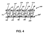
[0045]次に図4を参照すると、一実施形態による、5個のLEDのアレイ及び関連する平行化光学系の断面図が示されている。アレイ100には、この実施形態では、基板108の上に取り付けられた5個の個々のLED104が含まれている。基板108には、個々のLED104を関連する電源(図示せず)に接続している相互接続が含まれている。又、基板108は、LED104によって生成される熱を散逸させるように作用する、ヒートシンクなどの熱伝達機構を含むことも可能である。平行化光学系112は、基板108の上に、個々の関連するLED104を覆うように取り付けられており、平行化光学系112なしに生成されることになるビームに対して平行化された個々のLED104からの出力光パターンを形成している。図4の断面図は、混成型の設計を示したものであり、個々のLED104からの中心光線は、屈折コンポーネント116を介して平行化され、又、外側の光線は、反射コンポーネント120を介して平行化される。このような光コンポーネントは当分野で知られており、又、屈折コンポーネントは、光を所望のパターンで屈折させるように作用する光レンズを含むことができ、反射コンポーネントは、光を所望のパターンで反射させる鏡映面を生成するために堆積された反射物質を含むことができる。一実施形態では、LED104の平行化によって5%の範囲内のビーム角が生成される。他の実施形態では、LED104によって約2%のビーム角が生成される。又、図4の図解では、5個の光学系はすべて同じ方向を指しており、強度プロファイルが個々のビームの強度プロファイルと同じである距離プロファイルを有することになることに留意されたい。図3に関連して説明したように、二次光学系を全く有さないLEDは、通常、Cos(シータ)又はランベルトパターンを放射することになる。パワーが正の適切な焦点距離及び開口数を備えた光学系を追加することにより、放射パターンを平行化するように作用させることができ、それにより、光学系を全く有さないLEDによって生成されるパターンより狭い発散パターンを有するビームが生成される。
[0045] Referring now to FIG. 4, a cross-sectional view of an array of five LEDs and associated collimating optics is shown, according to one embodiment. The
[0046]遠視野強度に対する平行化の効果を理解するために、最初に、ランベルト放射パターンを備えた、平行化されていないLEDは、強度プロファイル
Io=PT/2[cos(θ)]
を有していることに留意されたい。上式でPTは総放出パワーである。平行化されたLEDは、プロファイル
Io=nPT/2[cos(nθ)]
を有することになる。標準ランベルトパターンは、120°の半値全幅(FWHM)角を有しており、又、平行化された5°FWHMパターンは、n=24を有することになる。したがって図4の実施形態の場合、アレイ内のLEDの各々は、平行化されたLEDに対する式で定義される強度を提供している。
[0046] To understand the effect of collimation on far-field intensity, first, an unparalleled LED with a Lambertian radiation pattern has an intensity profile Io = PT / 2 [cos (θ)].
Note that Where PT is the total emitted power. The collimated LED has a profile Io = nPT / 2 [cos (nθ)]
Will have. The standard Lambertian pattern has a full width at half maximum (FWHM) angle of 120 °, and the collimated 5 ° FWHM pattern will have n = 24. Thus, in the embodiment of FIG. 4, each of the LEDs in the array provides an intensity defined by the equation for the collimated LEDs.
[0047]次に図5を参照して、一実施形態によるLEDエレメントのアレイ150の斜視図について説明する。この実施形態では、5個のLED154のアレイが基板158の上に取り付けられている。図4に関連して上で説明したように、基板158には、同様に、個々のLED154を関連する電源(図示せず)に接続している相互接続が含まれている。又、基板158は、LED154によって生成される熱を散逸させるように作用する、ヒートシンクなどの熱伝達機構を含むことも可能である。平行化光学系162は、基板158の上に、個々の関連するLED154を覆うように取り付けられており、平行化光学系162なしに生成されることになるビームに対して平行化された個々のLED154からの出力光パターンを形成している。この実施形態では、LED154の出力を追加整形するために、フレネル型レンズ166が平行化光学系162に取り付けられており、それにより平行化された光出力をさらに整形している。これらのスナップオンレンズ166タイプは、より広い長円型のパターンを生成することができる。したがってLEDのアレイ150の出力を選択して、所望の特性を有する集合体パターン又は合成パターンを形成することができる。
[0047] Referring now to FIG. 5, a perspective view of an array 150 of LED elements according to one embodiment will be described. In this embodiment, an array of five
[0048]図6は、平行化光学系コンポーネント162を示したものである。平行化光学系162には、LED光エレメント154を受け取るように構成されたレンズ部分170が含まれている。レンズ170は、この実施形態では接着パッド174を使用して基板に取り付けられている。上で説明したように、フレネル型レンズをレンズ170に取り付けることができ、それにより光出力をさらに整形することができる。以下で詳細に追加説明するように、平行化されていないLEDビームパターン、狭く平行化されたLEDビームパターン、広角度及び/又は長円形投影LEDビームパターンの適切な組合せを使用することにより、所与の照明に必要なLEDの数を少なくする、出力が一様な低コストランプを達成することができる。
[0048] FIG. 6 shows a
[0049]図3に関連して上で説明したように、ほとんどすべてのLEDエミッタが、放出される光の強度がピークであり、且つ、中心線からの角度を関数として強度が低下する中央ローブを有している。又、これは、平行化され、且つ、整形された個々のLEDエミッタの場合もそうである。この中央ローブは、XYZ空間における方向座標が中央ローブの伝搬方向を表すベクトルと見なすことができ、そのベクトルの大きさが光のピーク強度である。平行化されていないLEDの場合、中央ローブベクトルは、ゼロ度に位置し、且つ、Pt/2に等しい大きさを有することになる。平行化されたLEDは、同様の方向及びnPt/2の大きさを有することになり、nは、上で説明したように平行化度である。 [0049] As explained above in connection with FIG. 3, almost all LED emitters have a central lobe where the intensity of the emitted light is peak and the intensity decreases as a function of angle from the centerline. have. This is also the case for individual LED emitters that are collimated and shaped. This central lobe can be regarded as a vector whose direction coordinate in the XYZ space represents the propagation direction of the central lobe, and the magnitude of the vector is the peak intensity of light. For an unparalleled LED, the central lobe vector will be located at zero degrees and have a magnitude equal to Pt / 2. The collimated LEDs will have a similar direction and a size of nPt / 2, where n is the degree of collimation as described above.
[0050]一様な照明パターンを有するランプを生成する場合、光エレメントの角強度も同じく考慮しなければならない。図7を参照すると、高さhのランプが面を照明している。所与の角度(θ)に対して、その角度に対する被照明面は、もっと遠くの被照明面に伸びて、法線から被照明面まで獲得することになる。一様な照明の場合、角強度は、
h[tan(θ+δ/2)−tan(θ−δ/2)]
の関係を追従しなければならない。典型的な照明環境では、ランプの間隔は、ランプの高さの形で定義される。つまりランプ間の間隔がnhである場合、考慮すべき最大角度は、tan(θmax)=n/2の場合である。一様な照明パターンの生成は、角度デルタシータ中に伝搬したLED光は、所望の強度の光を提供するためには、上に示した関係によって増加しなければならない状況に対応することになる。
[0050] When producing a lamp with a uniform illumination pattern, the angular intensity of the optical element must also be considered. Referring to FIG. 7, a lamp having a height h illuminates the surface. For a given angle (θ), the illuminated surface for that angle extends to the farther illuminated surface and is acquired from the normal to the illuminated surface. For uniform lighting, the angular intensity is
h [tan (θ + δ / 2) −tan (θ−δ / 2)]
Must follow the relationship. In a typical lighting environment, lamp spacing is defined in terms of lamp height. That is, when the interval between the lamps is nh, the maximum angle to be considered is when tan (θmax) = n / 2. The generation of a uniform illumination pattern will correspond to the situation where the LED light propagated in the angle delta theta must be increased by the relationship shown above in order to provide the desired intensity of light.
[0051]一実施形態では、LEDエレメントは、所望の出力パターンが提供されるよう、ランプアセンブリの中に配置するために選択される。ランプアセンブリ自体には、この実施形態の場合、異なる方向のLEDからの光出力を提供するために、異なる面に取り付けられるLEDが含まれている。平行化されない光学系、狭く平行化されたLEDビームパターン、広角度LEDビームパターン及び長円形投影LEDビームパターンと共に、光の方向を選択することにより、最少数のLEDエレメントで一様な照明パターンを形成する合成ランプ出力を展開することができる。このようなランプは、所望の照明レベル以上の照明を面に提供することができ、又、存在している場合、所望の照明領域全体に規定の照明レベルを提供するために必要な最少数を超える若干の追加LEDエレメントの存在に基づいて低減されるコストを有している。 [0051] In one embodiment, the LED elements are selected for placement in the lamp assembly such that a desired output pattern is provided. The lamp assembly itself includes, in this embodiment, LEDs that are mounted on different surfaces to provide light output from the LEDs in different directions. Along with non-collimated optics, narrowly collimated LED beam pattern, wide angle LED beam pattern and oval projection LED beam pattern, by selecting the direction of light, uniform illumination pattern with a minimum number of LED elements The resulting composite lamp output can be developed. Such lamps can provide illumination above the desired illumination level to the surface and, if present, provide the minimum number necessary to provide a defined illumination level across the desired illumination area. It has a reduced cost based on the presence of some additional LED elements.
[0052]このようなLEDランプアセンブリは、一実施形態では、所望の出力光パターンを生成するためのLEDエレメントの配置を設計することによって達成される。LED照明の場合、個々のLEDエレメントからの光強度がインコヒーレント追加によって直線的に追加される。LEDレイアウトの設計に際しては、個々のビームの1/2強度点が整合する場合、2つのビーム間の強度はほぼ等しいことが仮定される。このような実施形態の場合、上で言及したように、出力中央ローブは、XYZ空間における方向座標が中央ローブの伝搬方向を表すベクトルと見なすことができ、そのベクトルの大きさが光のピーク強度に対応することになる。一実施形態では、LED中央ローブベクトルが面に対して直角になるようにその面を生成することによって照明パターンを合成することができる。例えば、図8及び9は、照明領域上の異なる領域を照明するLEDエレメントを有する二次元面を示したものである。図8の例では、面200には、A〜Eの5個のLEDエレメントが含まれている。この例では、個々のLEDエレメントA〜Eには、個々のLEDから出力されるビームを平行にし、5°のビーム角を提供する平行化光学系が含まれている。領域A1〜E1は、対応するLEDエレメントA〜Eによってそれぞれ照明される照明領域部分を示している。図9は、異なる光学系が面250上の異なるLEDで実施された実施形態を示したものである。この実施形態では、「A」で示されている第1のLEDは、ビーム角が20°である平行化されていないLEDであり、したがって照明領域の部分A1を照明している。「B」で示されている第2のLEDには、ビーム角が5°のLEDを提供する平行化光学系が含まれており、したがって照明領域の部分B1を照明している。同様に、「C」で示されている第3のLEDにも、ビーム角が5°のLEDを提供する平行化光学系が含まれており、したがって照明領域の部分C1を照明している。面250に取り付けられている残りのLEDは、照明領域全体にわたる無矛盾の一様性で所望の強度の光を照明領域に提供するために、平行化されなくても、或いは平行化光学系及び/又は拡大レンズを含むことも可能である。
[0052] Such an LED lamp assembly is achieved, in one embodiment, by designing an arrangement of LED elements to produce a desired output light pattern. In the case of LED lighting, the light intensity from individual LED elements is added linearly by incoherent addition. In designing the LED layout, it is assumed that the intensities between the two beams are approximately equal if the ½ intensity points of the individual beams are matched. In such an embodiment, as mentioned above, the output central lobe can be regarded as a vector whose direction coordinate in XYZ space represents the propagation direction of the central lobe, and the magnitude of the vector is the peak intensity of the light. It will correspond to. In one embodiment, the illumination pattern can be synthesized by generating the surface so that the LED center lobe vector is perpendicular to the surface. For example, FIGS. 8 and 9 illustrate a two-dimensional surface having LED elements that illuminate different areas on the illumination area. In the example of FIG. 8, the
[0053]このような方法によれば、LEDをベースとする、所望の光照明パターンを形成するランプを製造することができる。ベクトルの組合せとしてのモデリングランプ出力は、所望の強度パターンを生成するためのポインティングベクトルの密度及び強度の生成、所望の強度を生成するための収斂ベクトルの密度の選択、LED出力のタイリングを提供するための平行ベクトルの密度の選択などの様々な技法を可能にすることができる。当然、ベクトルの組合せを使用して密度及びタイリングの両方の強度変化を生成することができる。さらに、LEDアレイ中における整形タイプの変化をモデル化することも可能である。理想的なパターンによって、ベクトルの方向の変化、ベクトルの密度の変化及びベクトルの長さ(強度)の変化に基づくベクトルの最適組合せが得られる。 [0053] According to such a method, an LED-based lamp that forms a desired light illumination pattern can be manufactured. Modeling lamp output as a vector combination provides generation of pointing vector density and intensity to generate desired intensity pattern, selection of convergent vector density to generate desired intensity, tiling LED output Various techniques may be possible, such as selection of the density of parallel vectors to do. Of course, a combination of vectors can be used to generate both density and tiling intensity changes. It is also possible to model shaping type changes in the LED array. An ideal pattern yields an optimal combination of vectors based on vector direction changes, vector density changes, and vector length (intensity) changes.
[0054]次に図10を参照して他の実施形態について説明する。複数のベクトル方向を有するランプ面にLEDを配置する代わりに、ビームステアリング光学系をLEDエレメントと組み合わせて使用して所望の照明パターンが生成される。図10の例では、面300には、2個のLEDエレメント304、308が含まれている。個々のLEDエレメントは、それぞれ関連するビームステアリング光学系312、316を有している。したがって、LED304から生成されるビームは、ビームステアリング光学系312を介して所望の方向に導かれる。同様に、LED308から生成されるビームは、ビームステアリング光学系316を介して所望の方向に導かれる。面には、特定のアプリケーションのニーズに合致する合成照明パターンを生成するための、特定のビームステアリング光学系と結合した異なるLED又はLEDのグループを備えた多数のLEDエレメントを含むことができる。さらに、他の実施形態では、複数のベクトル方向を備えたランプ面及びビームステアリング光学系の両方を共同して使用して、所望の照明パターンを生成することも可能である。
Next, another embodiment will be described with reference to FIG. Instead of placing the LEDs on a lamp surface having a plurality of vector directions, beam steering optics are used in combination with LED elements to produce the desired illumination pattern. In the example of FIG. 10, the
[0055]一実施形態では、パターン合成を使用して、照明装置からの所望の出力パターンに基づいて、その照明装置のための構成が決定される。この方法については、図11に概略的に記述されている。この実施形態では、道路内の対象の可視度の改善が期待されている。その理由は、道路照明の目的は、道路を見るためだけではなく、道路内に存在している可能性のあるあらゆる対象を見ることにあるからである。道路照明の分野で理解されているように、中央が存在しない二方向交通の街路上で一般的に使用される二方向照明装置は、正及び負の両方のコントラストによって微小ターゲット可視度(STV)を生成している。コントラストの反転は、通常、間隔サイクルにおいて、照明装置の真下の線上と、照明装置と照明装置の間の距離の約1/3の部分で合計2度生じる。千鳥形配置の場合、コントラスト反転の数が増加することになる。正のコントラストと負のコントラストの間に反転が存在する回数を少なくし、又、反転領域を狭くすることが望ましい。コントラストが正の領域では、ターゲット面を可能な限り明るくし、且つ、ターゲット面を見る背景となる道路表面を合理的に暗くしなければならない。コントラストが負の領域では、その逆にしなければならない。したがって、輝度の一様性が最大許容限界に近い一様性から最小許容限界まで変化する所望の平均舗道輝度を達成することが望ましい。高い値のSTVを達成するためには、照明装置の分布及び間隔を適切に選択することが極めて重要である。 [0055] In one embodiment, pattern composition is used to determine a configuration for a lighting device based on a desired output pattern from the lighting device. This method is schematically described in FIG. In this embodiment, improvement of the visibility of the object in the road is expected. The reason is that the purpose of road lighting is not only to see the road, but to see any object that may be present in the road. As is understood in the field of road lighting, two-way lighting devices commonly used on two-way traffic streets where there is no center are low target visibility (STV) with both positive and negative contrast. Is generated. Contrast reversal typically occurs a total of two times in the interval cycle, on the line directly below the illuminator and at about 1/3 of the distance between the illuminators. In a staggered arrangement, the number of contrast inversions will increase. It is desirable to reduce the number of inversions between positive contrast and negative contrast and to narrow the inversion region. In areas where the contrast is positive, the target surface must be as bright as possible, and the road surface as the background for viewing the target surface must be reasonably darkened. The opposite must be done in areas where the contrast is negative. Accordingly, it is desirable to achieve a desired average pavement luminance where the luminance uniformity varies from a uniformity close to the maximum allowable limit to a minimum allowable limit. In order to achieve high values of STV, it is very important to properly select the distribution and spacing of the lighting devices.
[0056]もう一度図11を参照すると、高さhの取付け高さ及び分離dを有するランプ320が、道路324上の進行方向に対する関係で示されている。ライトの前方の照明パターンの主要範囲はxで示されており、又、ライトの後方の照明パターンの主要範囲はyで示されており、ライト間の重畳はzで示されている。ライトから、ポストから離れた地面までの角度は、シータで画定されており、ライトのポールは、シータ=0である。所望の照明パターンは、距離xが進行中の自動車運転者に見える角度未満の角度に対応するように、ライトの前方の照明パターンの主要範囲を有することになる。それにより、道路表面320を進行方向に走行中の自動車運転者が遭遇するグレアが抑制される。ライトの後方の主要範囲yは、過剰な侵入などの問題によって制限されており、反対車線の自動車運転者にグレアを生成している。さらに、ライト間の重畳領域zを最小化することによってターゲット可視度が改善される。このターゲット可視度の改善は、光が弱くなる領域を慎重に制御することによって達成することができる。一様な照明パターンは、正接関数として本質的に記述される角強度を有することになる。一実施形態では、比較的狭いビームを使用して、tan(シータ)角強度線からの、可能な限り速やかにゼロに到達する移行への移行であるこの終端が提供される。この移行線は、光の最も外側のビーム成分のビームパターンを追従しなければならない。パターン合成プロセスによって画定される、高度に平行化されたビームを使用して、ベイリングルミナンス、ベイリンググレアを最小化し、且つ、ターゲット可視度を改善するために必要なパターン終端特性を生成することができる。図12は、ランプ320及び領域x、y及びzを備えた一例示的道路324の平面図を示したものである。
[0056] Referring once again to FIG. 11, a
[0057]図12の図解は、道路324の1つ又は複数の車線が単一の進行方向を有しているアプリケーションに使用するために適している。このようなアプリケーションには、分離高速道路及び一方向主要道路を含むことができる。光を道路に向けて導く(進行方向に沿って)ための最適角度は、60度と76度の間、より好ましくは約72度と76度の間であることが分かっている。上流側の光のための最適角度(進行方向中への)は、0度と約50度の間であることが分かっている。交通の流れに向かって、より大きい角度で放出される光は、運転者の目に直接射し込み、安全上の危険をもたらす可能性がより一層高い。図11の実施形態では、LEDモジュールは、進行方向に沿った方向に約72度で、又、進行方向中への方向に約45度で光出力を提供するために、個々のランプの中に構成されている。
[0057] The illustration of FIG. 12 is suitable for use in applications where one or more lanes of the
[0058]対向する進行方向を有する2車線(又は3車線以上)の交通が道路上に存在するアプリケーションの場合、図12に示されているランプ320のようなランプは、1つの方向の交通では、グレアがより多くなり、したがって微小ターゲットの可視度が低下するため、それほど適していない。図13に示されている他の実施形態では、個々の照明装置は、道路表面350の被照明領域が、道路350内の特定の車線の進行方向に基づいてシフトする光パターンを出力する。この実施形態では、照明装置354は、道路350内の第1の車線の進行方向に沿って約72度の角度で光を出力しており、この被照明領域は、図13に領域「a」で識別されている。照明装置354は、第1の車線の進行方向に対して約45度の角度で光を出力しており、この被照明領域は、図13に領域「b」で識別されている。同様に、照明装置354は、第2の車線の進行方向に対して約45度の角度で光を出力しており、又、第2の車線の進行方向に対して約72度の角度で光を出力しており、これらの領域は、図13にそれぞれ領域「c」及び「d」で識別されている。
[0058] For applications where two lanes (or more than three lanes) of traffic with opposite traveling directions are present on the road, a ramp such as
[0059]これらの所望の出力パターンを達成する照明取付具を設計するためにパターン合成を利用するための設計手順には、いくつかの要素が含まれている。一実施形態では、LEDパッケージのための光出力のモデルを提供する測光ファイルが提供される。このようなファイルは、LED製造者が提供することができ、或いは光学研究室で生成することができる。このLED測光ファイルを使用してランプモデルが構築される。次に、任意の二次光学系と組み合わせたLEDのための測光ファイルが生成される。必要な二次光学系を利用することができない場合は、Rhino及びSolidworksなどのモデリングサーフェシング或いはソリッドモデリングソフトウェアを使用してそれらを設計することができる。次に、AGI32などの照明装置システムからの水平及び/又は垂直面の照度を予測する照明アプリケーションソフトウェアを使用して、個々のLED又はLEDモジュールの照準が定められる。LEDが配置され、且つ、照準が定められると、照明アプリケーションソフトウェアを使用してシステムの性能が計算される。照準を微調整するためには、場合によってはこのステップを何度か反復しなければならない。この時点で、サーフェシングソフトウェアを使用して、いわゆるディスク又はモジュールを構築することができる。本明細書において参照されているディスク又はモジュールは、単一の光源として結合され、且つ、モデル化されたLEDの集積である。次に、サーフェシングソフトウェアを使用して、照明アプリケーションソフトウェアによって生成される線図毎にディスクの照準が定められる。次に、Solidworksなどのソリッドモデリングソフトウェアを使用して、ハウジング、レンズ及び他のコンポーネントである照明装置がモデル化される。次に、新しい照明装置の測光性能が模擬される。次に、この照明装置モデルをAGI32などの照明アプリケーションソフトウェアに使用して、様々な照明アプリケーションにおける照明装置の性能を計算することができる。 [0059] The design procedure for utilizing pattern synthesis to design lighting fixtures that achieve these desired output patterns includes several elements. In one embodiment, a photometric file is provided that provides a model of light output for an LED package. Such a file can be provided by the LED manufacturer or can be generated in an optical laboratory. A lamp model is constructed using this LED photometric file. Next, a photometric file for the LED combined with any secondary optics is generated. If the required secondary optics are not available, they can be designed using modeling surfacing or solid modeling software such as Rhino and Solidworks. The individual LED or LED module is then aimed using lighting application software that predicts the illuminance of the horizontal and / or vertical plane from a lighting system such as AGI32. Once the LEDs are placed and aimed, the lighting application software is used to calculate the system performance. In order to fine tune the aim, this step may have to be repeated several times. At this point, surfacing software can be used to build a so-called disk or module. The disk or module referred to herein is an integration of LEDs that are combined and modeled as a single light source. The surfacing software is then used to aim the disc for each diagram generated by the lighting application software. Next, solid modeling software such as Solidworks is used to model the lighting device, which is the housing, lens, and other components. Next, the photometric performance of the new lighting device is simulated. This lighting device model can then be used in lighting application software such as AGI 32 to calculate lighting device performance in various lighting applications.
[0060]次に図14〜16を参照して、一実施形態のLEDベースランプアセンブリについて説明する。この実施形態では、ランプアセンブリ400には、多数の異なる角度の取付け面406を有する面404が含まれており、これらの取付け面406にLEDアセンブリ408が取り付けられている。ランプアセンブリ400は、主軸410の方向に光出力を提供している。LEDアセンブリ408は、この実施形態では、図4及び5に関連して既に説明したLEDアレイ100及び150に類似している。LEDアセンブリ408には、この実施形態では、5個のLEDエレメントのアレイが含まれており、又、LEDに結合された平行化光学系又は他のビーム整形光学系を含むことができる。この実施形態のランプアセンブリ400は、従来の150ワットハロゲン化金属タイプの建築用街路ライトの取替え品を提供するように設計されている。LEDアセンブリ408には、1つのタイプの標準LEDが含まれており、一実施形態では、このLEDは、約500〜600mAの電流で動作し、約170〜250ルーメンの出力フラックスを提供する白色LEDである。
[0060] Referring now to FIGS. 14-16, one embodiment of an LED base lamp assembly will be described. In this embodiment, the
[0061]LEDアセンブリ408には、一実施形態では、3つのタイプの平行化、つまり5度の狭いビーム、20度のビーム(平行化されていない)及び20度×5度の長円形ビームが含まれている。この実施形態のLEDアセンブリには、上で言及したように、5個のLEDが含まれており、LED出力のタイリングを提供している。このようなアセンブリによれば、5−エレメントアレイを面404に取り付けることができるため、製造が単純化される。しかしながら、個々のLEDを面に取り付けることができ、或いはアレイ上のLEDの数が異なるLEDのアレイを使用することも可能であることは容易に認識されよう。他の実施形態では、LEDアセンブリ408の各々には、出力光を2度の狭いビームに平行化するコリメータが含まれており、次に、出力光を異なる所望の広がりに拡大するための拡大光学系をLED/コリメータの上に配置することができる。このような一実施形態では、個々のランプアセンブリは、30フィートの取付け高さ、及び取付け高さの6倍(180フィート)のランプ間距離を有しており、個々のランプは、ランプの位置から道路の前後に取付け高さの+/−3倍より若干広い領域を照明している。この実施形態では、ランプの中心線から取付け高さの3倍及びそれを超える(90+フィート)領域を指しているLEDは、拡大レンズには一切結合されていない。ランプの中心線から取付け高さの2.5倍と3倍の間(75〜90フィート)の領域を指しているLEDは、5度の広がりを有する拡大レンズに結合されている。ランプの中心線から取付け高さの2倍と2.5倍の間(60〜75フィート)の領域を指しているLEDは、15度の広がりを有する拡大レンズに結合されている。ランプの中心線から取付け高さの1倍と2倍の間(30〜60フィート)の領域を指しているLEDは、25度の広がりを有する拡大レンズに結合されている。最後に、ランプの中心線から取付け高さのゼロ倍と1倍の間(0〜30フィート)の領域を指しているLEDは、50度の広がりを有する拡大レンズに結合されている。
[0061] The
[0062]次に図17〜20を参照して、他の実施形態のLEDベースランプアセンブリ500について説明する。この実施形態では、ランプアセンブリ500は、「ベル」形アセンブリであり、外部ハウジング504及び外部レンズ508が含まれている。いくつかの取付けサブアセンブリ512、516、520がハウジング504の中にアセンブルされており、個々のサブアセンブリ512、516、520は、多数の異なる角度の取付け面524を有しており、この取付け面524の一方の面にLEDアセンブリ528が取り付けられており、又、熱散逸デバイス532が反対側の面に取り付けられている。ランプアセンブリ500は、破線510によって識別されている領域内に光出力を提供している。LEDアセンブリ528は、この実施形態では、図4及び5に関連して既に説明したLEDアレイ100及び150に類似している。LEDアセンブリ528には、この実施形態では、3/2構成で配置された5個のLEDエレメントのアレイが含まれており、又、LEDに結合された平行化光学系又は他のビーム整形光学系を含むことができる。この実施形態のランプアセンブリ500は、従来の150ワットハロゲン化金属タイプの建築用街路ライトの取替え品を提供するように設計されている。LEDアセンブリ528には、1つのタイプの標準LEDが含まれており、一実施形態では、このLEDは、約500〜600mAの電流で動作し、約170〜250ルーメンの出力フラックスを提供する白色LEDである。この実施形態のLEDアセンブリ528には、上で言及したように、5個のLEDが含まれており、LED出力のタイリングを提供し、又、面524への5−エレメントアレイの取付けを可能にすることによって製造を単純化している。しかしながら、個々のLEDを面に取り付けることができ、或いはアレイ上のLEDの数又は構成が異なるLEDのアレイを使用することも可能であることは容易に認識されよう。
[0062] Referring now to FIGS. 17-20, another embodiment of an LED
[0063]他の実施形態では、LEDアセンブリ528の各々には、出力光を2度の狭いビームに平行化するコリメータが含まれており、次に、出力光を異なる所望の広がりに拡大するための拡大光学系をLED/コリメータの上に配置することができる。このような一実施形態では、個々のランプアセンブリは、30フィートの取付け高さ、及び取付け高さの6倍(180フィート)のランプ間距離を有しており、個々のランプは、ランプの位置から道路の前後に取付け高さの+/−3倍より若干広い領域を照明している。この実施形態では、ランプの中心線から取付け高さの3倍及びそれを超える(90+フィート)領域を指しているLEDは、拡大レンズには一切結合されていない。ランプの中心線から取付け高さの2.5倍と3倍の間(75〜90フィート)の領域を指しているLEDは、5度の広がりを有する拡大レンズに結合されている。ランプの中心線から取付け高さの2倍と2.5倍の間(60〜75フィート)の領域を指しているLEDは、15度の広がりを有する拡大レンズに結合されている。ランプの中心線から取付け高さの1倍と2倍の間(30〜60フィート)の領域を指しているLEDは、25度の広がりを有する拡大レンズに結合されている。最後に、ランプの中心線から取付け高さのゼロ倍と1倍の間(0〜30フィート)の領域を指しているLEDは、50度の広がりを有する拡大レンズに結合されている。
[0063] In other embodiments, each of the
[0064]上で説明した実施形態から分かるように、グレアが少ない改良型可視度を提供する非対称光分布を有する正コントラスト道路照明システムを含む、いくつかの特徴を提供する発光体が提供される。システムは、IESNA RP−8−2000及びAASHTO高速道路照明要求事項を満足し、又、照明装置ポール間隔に対して、5:1又はそれより良好な取付け高さ比を満足する。本明細書において説明されているいくつかの実施形態のシステムによれば、正のコントラストを有する可視度が改善され、又、全カットオフを達成し、且つ、照明装置から上向きに投射される光の量を少なくすることにより、光汚染を抑制するアップライトが抑制される。抑制されたアップライトは、さらに、光エレメントからのあらゆる迷光がランプハウジングの中に封じ込められるよう、交差パターンの複数の光エレメントによって生成される光のビームを有することによって達成される。このような抑制されたアップライトと、より指向性が強く、且つ、目標が定められた出力パターンによって提供される抑制された侵入により、光汚染が著しく抑制され、又、多くの管轄区域に存在している「ダークスカイ」ゴールの達成が促進される。さらに、いくつかの実施形態の照明システムによれば、より良好なランプの利用及びより大きい頂角での光出力を提供することによってエネルギーが節約される。 [0064] As can be seen from the embodiments described above, a light emitter is provided that provides several features, including a positive contrast road lighting system with an asymmetric light distribution that provides improved visibility with less glare. . The system meets IESNA RP-8-2000 and AASHTO highway lighting requirements, and satisfies a 5: 1 or better mounting height ratio for lighting pole spacing. The systems of some embodiments described herein improve visibility with positive contrast, achieve full cut-off, and project upward from the lighting device By reducing the amount of light, uprights that suppress light contamination are suppressed. Suppressed upright is further achieved by having a beam of light generated by a plurality of light elements in a cross pattern so that any stray light from the light elements is contained within the lamp housing. Such suppressed uprights and more directional and suppressed intrusions provided by targeted output patterns significantly reduce light pollution and are present in many jurisdictions Achievement of the “Dark Sky” goal is promoted. Furthermore, the lighting system of some embodiments saves energy by providing better lamp utilization and light output at a larger apex angle.
[0065]他の実施形態では、本開示により、LEDをベースとするランプから所望の照明パターンを生成するための方法が提供される。この方法には、実施すべき照明パターンを決定するステップが含まれている。照明パターンは、最小照明要求事項及びランプの最小高さ、等々などの特定のタイプの照明アプリケーションの仕様に基づいて決定することができる。又、照明パターンは、特定のアプリケーションに対して提供される基準の特注セットに基づくことも可能である。例えばランプが街路ライトとして使用される場合、最小照明要求事項を含む、街路照明に対する様々な仕様が存在している。このような場合、関連する仕様は、照明パターンを決定する際の要因の1つである。照明パターンを決定する際の他の要因は、ランプアセンブリの高さ及び間隔である。ランプアセンブリの高さ及び間隔は、特定のアプリケーションの仕様に基づいて決定することができる。例えば、街路照明アプリケーションは、道路上に配置されるランプの最大ランプ間隔及び最小高さに関する仕様を有することができる。別法としては、ランプアセンブリ及び関連するLEDエレメントが設計された後に、ランプアセンブリの高さ及び間隔を決定することも可能である。例えば、ランプアセンブリは、特定の高さに配置された場合に、特定の領域全体にわたって一様な照明を提供するように設計することができる。このような場合、ランプアセンブリの間隔は、照明される領域に対する照明の所望の一様性に基づいて決定される。 [0065] In other embodiments, the present disclosure provides a method for generating a desired illumination pattern from an LED-based lamp. The method includes determining the illumination pattern to be performed. The lighting pattern can be determined based on the specifications of a particular type of lighting application, such as minimum lighting requirements and minimum lamp height, and so on. The illumination pattern can also be based on a custom set of criteria provided for a particular application. For example, when lamps are used as street lights, there are various specifications for street lighting, including minimum lighting requirements. In such a case, the related specification is one of the factors in determining the illumination pattern. Another factor in determining the illumination pattern is the height and spacing of the lamp assembly. The height and spacing of the lamp assembly can be determined based on the specifications of the particular application. For example, a street lighting application may have specifications regarding the maximum lamp spacing and minimum height of lamps placed on the road. Alternatively, the height and spacing of the lamp assembly can be determined after the lamp assembly and associated LED elements are designed. For example, the lamp assembly can be designed to provide uniform illumination over a particular area when placed at a particular height. In such a case, the spacing of the lamp assemblies is determined based on the desired uniformity of illumination for the illuminated area.
[0066]ランプに使用される1つ又は複数のタイプのLEDエレメントが選択され、又、選択されたLEDエレメントによって提供される照明が、異なるタイプの平行化に対して決定され、且つ、ランプアセンブリの主軸に対する異なる角度に対して決定される。照明される領域の最小フラックスレベルを含む照明の一様性が決定される。次に、LEDが取付け面に取り付けられると、ランプが所望の照明パターンを所望の一様性で提供するよう、主軸に対して異なる角度を有する多数の異なる取付け面を含んだランプ面が決定される。一様な角強度が提供されるよう、LEDエレメントからの出力光の強度及びビーム角が選択される。 [0066] One or more types of LED elements used in the lamp are selected, and the illumination provided by the selected LED elements is determined for different types of collimation, and the lamp assembly Are determined for different angles with respect to the main axis. The illumination uniformity, including the minimum flux level of the illuminated area, is determined. Next, when the LED is mounted on the mounting surface, a lamp surface is determined that includes a number of different mounting surfaces having different angles with respect to the main axis so that the lamp provides the desired illumination pattern with the desired uniformity. The The intensity and beam angle of the output light from the LED element are selected so that a uniform angular intensity is provided.
[0067]開示した実施形態についての以上の説明は、すべての当業者による本発明の構築又は本発明の使用を可能にするためのものである。当業者には、これらの実施形態に対する様々な修正が容易に明らかであり、又、本明細書において定義されている一般原理は、本発明の精神又は範囲を逸脱することなく他の実施形態に適用することができる。したがって本発明は、本明細書において示されている実施形態に限定されることは意図されておらず、本明細書において開示されている原理及び新規な特徴に矛盾しない最も広義の範囲と調和するものとする。 [0067] The above description of the disclosed embodiments is provided to enable any person skilled in the art to make or use the present invention. Various modifications to these embodiments will be readily apparent to those skilled in the art, and the general principles defined herein may be used in other embodiments without departing from the spirit or scope of the invention. Can be applied. Accordingly, the present invention is not intended to be limited to the embodiments shown herein, but is consistent with the broadest scope consistent with the principles and novel features disclosed herein. Shall.
Claims (26)
複数の取付け面を有するハウジングであり、前記複数の取付け面が、当該ランプアセンブリによって照明される面に平行の第1の平面に対して複数の異なる角度を有する面を備える、ハウジングと、
前記取付け面の各々に取り付けられる少なくとも1つの固体光エレメントであり、複数の前記固体光エレメントからなる少なくとも1つのサブセットの各々が、前記第1の平面に対して直角をなしている第2の平面と交差し、且つ、前記ハウジングの中心線と交差する対応する個々の主軸に沿って光出力を提供し、複数の前記固体光エレメントの前記光出力が結合して合成照明パターンを形成する、少なくとも1つの固体光エレメントと
を備え、
複数の前記固体光エレメントからなる前記サブセットの少なくとも各々からの前記光出力の特定の強度及びビーム角によって、一様な角強度が実現される、ランプアセンブリ。 A lamp assembly,
A housing having a plurality of mounting surfaces, the plurality of mounting surfaces comprising surfaces having a plurality of different angles with respect to a first plane parallel to a surface illuminated by the lamp assembly;
A second plane that is at least one solid-state optical element mounted on each of the mounting surfaces, each of the at least one subset of the plurality of solid-state optical elements being perpendicular to the first plane. And providing light output along corresponding individual principal axes that intersect the centerline of the housing, and the light outputs of the plurality of solid state light elements combine to form a combined illumination pattern, at least One solid-state optical element and
A lamp assembly, wherein a uniform angular intensity is achieved by a specific intensity and beam angle of the light output from at least each of the subsets comprising a plurality of the solid state light elements.
照明パターンを形成するように構成され、且つ、当該ランプアセンブリから当該ランプアセンブリによって照明される面まで延びる主軸を有する前記ランプアセンブリに取り付けられる複数の固体光エレメントと、
前記主軸に対して複数の角度を有する取付け面であり、該取付け面に複数の前記固体光エレメントが取り付けられ、それらの各々が前記取付け面に対して直角の出力軸に沿って光出力を提供し、複数の前記固体光エレメントからなる少なくとも1つのサブセットの前記出力軸が、前記主軸を含んだ平面及び前記ランプアセンブリの中心線と交差する、取付け面と、
複数の前記固体光エレメントからなる少なくとも1つのサブセットに取り付けられる複数の第2の光学系と、
を備え、
前記第2の光学系の各々は、対応する前記固体光エレメントの前記光出力を平行化するように構成され、
前記複数の第2の光学系は、前記固体ランプアセンブリからの光出力の一様な角強度を提供する、固体ランプアセンブリ。 A solid lamp assembly,
A plurality of solid state light elements attached to the lamp assembly configured to form an illumination pattern and having a major axis extending from the lamp assembly to a surface illuminated by the lamp assembly;
A mounting surface having a plurality of angles with respect to the main axis, the plurality of solid optical elements being mounted on the mounting surface, each providing light output along an output axis perpendicular to the mounting surface A mounting surface wherein the output axis of at least one subset of the plurality of solid state light elements intersects a plane including the main axis and a centerline of the lamp assembly;
A plurality of second optical systems attached to at least one subset of the plurality of solid state optical elements;
With
Each of the second optical systems is configured to collimate the light output of the corresponding solid state optical element;
The solid state lamp assembly, wherein the plurality of second optical systems provide uniform angular intensity of light output from the solid state lamp assembly.
当該ランプアセンブリから当該ランプアセンブリによって照明される面まで延びる主軸を有するハウジングであり、複数の取付け面を備えるハウジングと、
前記取付け面に取り付けられる複数の固体光エレメントであって、複数の前記固体光エレメントからなる少なくとも1つのサブセットの各々が、第1の軸に対して直角をなしている第2の平面と交差し、且つ、前記ハウジングの中心線と交差する対応する個々の軸に沿って光出力のビームを提供する、固体光エレメントと、
前記固体光エレメントからなる少なくとも1つのサブセットに取り付けられる、対応する個々の固体光エレメントからの出力光を平行にする複数の平行化コンポーネントと、
前記平行化コンポーネントからなる少なくとも1つのサブセットに取り付けられる複数の拡大光学系であり、前記平行化コンポーネントからの前記出力光を、前記固体光エレメントによって照明される対象の前記固体光エレメントからの距離に基づいて選択されるビーム幅に拡大し、前記ランプアセンブリからの光出力の一様な角強度を提供する、複数の拡大光学系と
を備える、ランプアセンブリ。 A lamp assembly,
A housing having a main shaft extending from the lamp assembly to a surface illuminated by the lamp assembly, the housing comprising a plurality of mounting surfaces;
A plurality of solid state optical elements attached to the mounting surface, wherein each of the at least one subset of the plurality of solid state optical elements intersects a second plane perpendicular to the first axis. A solid state optical element that provides a beam of light output along a corresponding individual axis that intersects the centerline of the housing;
A plurality of collimating components attached to at least one subset of said solid state light elements for collimating output light from corresponding individual solid state light elements;
Wherein a plurality of magnifying optical system is attached to at least one subset of the collimating components, the output light from the collimating component, distance from the solid state light elements of the subject illuminated by the solid state light element A plurality of magnifying optics that expands to a beam width selected based on and provides uniform angular intensity of light output from the lamp assembly.
Applications Claiming Priority (3)
| Application Number | Priority Date | Filing Date | Title |
|---|---|---|---|
| US7774708P | 2008-07-02 | 2008-07-02 | |
| US61/077,747 | 2008-07-02 | ||
| PCT/US2009/049629 WO2010003126A2 (en) | 2008-07-02 | 2009-07-02 | Light unit with light output pattern synthesized from multiple light sources |
Publications (2)
| Publication Number | Publication Date |
|---|---|
| JP2011527091A JP2011527091A (en) | 2011-10-20 |
| JP5526302B2 true JP5526302B2 (en) | 2014-06-18 |
Family
ID=41466616
Family Applications (1)
| Application Number | Title | Priority Date | Filing Date |
|---|---|---|---|
| JP2011516893A Expired - Fee Related JP5526302B2 (en) | 2008-07-02 | 2009-07-02 | Optical unit with light output pattern synthesized from multiple light sources |
Country Status (7)
| Country | Link |
|---|---|
| US (3) | US8635049B2 (en) |
| EP (1) | EP2324279A4 (en) |
| JP (1) | JP5526302B2 (en) |
| CN (1) | CN102144120A (en) |
| AU (1) | AU2009266799A1 (en) |
| CA (2) | CA2729785C (en) |
| WO (1) | WO2010003126A2 (en) |
Families Citing this family (49)
| Publication number | Priority date | Publication date | Assignee | Title |
|---|---|---|---|---|
| CN102144120A (en) | 2008-07-02 | 2011-08-03 | 萨诺维亚能源科技股份有限公司 | Light unit with light output pattern synthesized from multiple light sources |
| WO2010129373A2 (en) * | 2009-04-28 | 2010-11-11 | Sunovia Energy Technologies, Inc. | Retrofit system for converting an existing luminaire into a solid state lighting luminaire |
| JP2011222514A (en) * | 2010-04-11 | 2011-11-04 | Sd Hess Lighting Kk | Led lighting apparatus |
| US10883702B2 (en) | 2010-08-31 | 2021-01-05 | Ideal Industries Lighting Llc | Troffer-style fixture |
| US9581312B2 (en) | 2010-12-06 | 2017-02-28 | Cree, Inc. | LED light fixtures having elongated prismatic lenses |
| US9494293B2 (en) | 2010-12-06 | 2016-11-15 | Cree, Inc. | Troffer-style optical assembly |
| CN102147289A (en) * | 2011-01-14 | 2011-08-10 | 上海理工大学 | Illumination system for portable spectrograph |
| US10823347B2 (en) | 2011-07-24 | 2020-11-03 | Ideal Industries Lighting Llc | Modular indirect suspended/ceiling mount fixture |
| KR101377144B1 (en) * | 2011-10-05 | 2014-03-27 | 주식회사 케이엠더블유 | Illuminating method of LED Illiminator |
| US9423117B2 (en) | 2011-12-30 | 2016-08-23 | Cree, Inc. | LED fixture with heat pipe |
| US10544925B2 (en) | 2012-01-06 | 2020-01-28 | Ideal Industries Lighting Llc | Mounting system for retrofit light installation into existing light fixtures |
| US9777897B2 (en) | 2012-02-07 | 2017-10-03 | Cree, Inc. | Multiple panel troffer-style fixture |
| US9310038B2 (en) | 2012-03-23 | 2016-04-12 | Cree, Inc. | LED fixture with integrated driver circuitry |
| US10054274B2 (en) | 2012-03-23 | 2018-08-21 | Cree, Inc. | Direct attach ceiling-mounted solid state downlights |
| US9494294B2 (en) | 2012-03-23 | 2016-11-15 | Cree, Inc. | Modular indirect troffer |
| US9360185B2 (en) * | 2012-04-09 | 2016-06-07 | Cree, Inc. | Variable beam angle directional lighting fixture assembly |
| US9874322B2 (en) | 2012-04-10 | 2018-01-23 | Cree, Inc. | Lensed troffer-style light fixture |
| DE102012007301A1 (en) * | 2012-04-10 | 2013-10-10 | Erco Gmbh | Collimator optics system |
| US9285099B2 (en) | 2012-04-23 | 2016-03-15 | Cree, Inc. | Parabolic troffer-style light fixture |
| WO2014011665A1 (en) * | 2012-07-09 | 2014-01-16 | Evolucia Lighting, Inc. | Light unit with light output pattern synthesized from multiple light sources and modular refractors |
| CN105121954A (en) * | 2012-07-09 | 2015-12-02 | 伊沃卢西亚照明股份有限公司 | Methods and apparatuses for constructing a universal luminaire |
| US8974077B2 (en) | 2012-07-30 | 2015-03-10 | Ultravision Technologies, Llc | Heat sink for LED light source |
| US9582671B2 (en) | 2014-03-06 | 2017-02-28 | Sensity Systems Inc. | Security and data privacy for lighting sensory networks |
| US9374870B2 (en) | 2012-09-12 | 2016-06-21 | Sensity Systems Inc. | Networked lighting infrastructure for sensing applications |
| US9797565B2 (en) | 2012-10-31 | 2017-10-24 | Thomas & Betts International Llc | LED engine for emergency lighting |
| US9754807B2 (en) * | 2013-03-12 | 2017-09-05 | Applied Materials, Inc. | High density solid state light source array |
| US10648643B2 (en) | 2013-03-14 | 2020-05-12 | Ideal Industries Lighting Llc | Door frame troffer |
| US10030852B2 (en) * | 2013-03-15 | 2018-07-24 | Kenall Manufacturing Company | Downwardly directing spatial lighting system |
| US9052075B2 (en) | 2013-03-15 | 2015-06-09 | Cree, Inc. | Standardized troffer fixture |
| US9494844B2 (en) * | 2013-03-25 | 2016-11-15 | Applied Minds Llc | Light source for video communication device |
| US9456293B2 (en) | 2013-03-26 | 2016-09-27 | Sensity Systems Inc. | Sensor nodes with multicast transmissions in lighting sensory network |
| US9933297B2 (en) | 2013-03-26 | 2018-04-03 | Sensity Systems Inc. | System and method for planning and monitoring a light sensory network |
| US20140293603A1 (en) * | 2013-03-27 | 2014-10-02 | Sensity Systems, Inc. | Led light bulb replacement with adjustable light distribution |
| USD786471S1 (en) | 2013-09-06 | 2017-05-09 | Cree, Inc. | Troffer-style light fixture |
| US10451253B2 (en) | 2014-02-02 | 2019-10-22 | Ideal Industries Lighting Llc | Troffer-style fixture with LED strips |
| USD772465S1 (en) | 2014-02-02 | 2016-11-22 | Cree Hong Kong Limited | Troffer-style fixture |
| USD807556S1 (en) | 2014-02-02 | 2018-01-09 | Cree Hong Kong Limited | Troffer-style fixture |
| USD749768S1 (en) | 2014-02-06 | 2016-02-16 | Cree, Inc. | Troffer-style light fixture with sensors |
| US9746370B2 (en) | 2014-02-26 | 2017-08-29 | Sensity Systems Inc. | Method and apparatus for measuring illumination characteristics of a luminaire |
| US10362112B2 (en) | 2014-03-06 | 2019-07-23 | Verizon Patent And Licensing Inc. | Application environment for lighting sensory networks |
| US10417570B2 (en) | 2014-03-06 | 2019-09-17 | Verizon Patent And Licensing Inc. | Systems and methods for probabilistic semantic sensing in a sensory network |
| US10527225B2 (en) | 2014-03-25 | 2020-01-07 | Ideal Industries, Llc | Frame and lens upgrade kits for lighting fixtures |
| CN104132316A (en) | 2014-07-23 | 2014-11-05 | 苏州吉视电子科技有限公司 | LED light source for industrial detection |
| CN104696751A (en) * | 2015-03-09 | 2015-06-10 | 苏州昆仑工业设计有限公司 | Novel multilayered lamp |
| US10012354B2 (en) | 2015-06-26 | 2018-07-03 | Cree, Inc. | Adjustable retrofit LED troffer |
| CN109073209B (en) * | 2016-04-19 | 2022-06-03 | 豪倍照明公司 | Wall-mounted light fixture and thermal insert for the same |
| CN106136494B (en) * | 2016-09-09 | 2018-02-27 | 广东乐源数字技术有限公司 | The Intelligent bracelet that a kind of achievable touch-control resets |
| FI129663B (en) | 2019-11-20 | 2022-06-15 | Procemex Oy Ltd | An LED matrix lighting device |
| US11739910B2 (en) | 2019-12-16 | 2023-08-29 | Lumileds Llc | LED arrays with self-stabilizing torch functions |
Family Cites Families (56)
| Publication number | Priority date | Publication date | Assignee | Title |
|---|---|---|---|---|
| US4041306A (en) * | 1975-12-15 | 1977-08-09 | Kim Lighting, Inc. | Luminaire and reflector therefor |
| US4694382A (en) | 1986-12-23 | 1987-09-15 | Hubbell Incorporated | Reflector for roadway lighting luminaire |
| US5497306A (en) * | 1993-02-01 | 1996-03-05 | Donnelly Corporation | Exterior vehicle security light |
| US5622427A (en) | 1993-09-03 | 1997-04-22 | Simplex Time Recorder Company | Emergency strobe light |
| US5803590A (en) | 1996-03-08 | 1998-09-08 | Thomas & Betts Corporation | Roadway luminaire |
| TW330233B (en) * | 1997-01-23 | 1998-04-21 | Philips Eloctronics N V | Luminary |
| AU138395S (en) | 1998-07-02 | 1999-09-14 | Financiere Des Applications De Lelectricite N V | Reflector for lamps |
| WO2000035402A1 (en) * | 1998-12-17 | 2000-06-22 | Getinge/Castle, Inc. | Illumination system adapted for surgical lighting |
| US6547423B2 (en) * | 2000-12-22 | 2003-04-15 | Koninklijke Phillips Electronics N.V. | LED collimation optics with improved performance and reduced size |
| US7152996B2 (en) | 2001-04-27 | 2006-12-26 | Altman Stage Lighting Co., Inc. | Diode lighting system |
| JP2004200102A (en) * | 2002-12-20 | 2004-07-15 | Kankyo Shomei:Kk | Exterior illumination fixture by white light emitting diode |
| JP4206773B2 (en) * | 2003-02-13 | 2009-01-14 | 東芝ライテック株式会社 | lighting equipment |
| KR100559076B1 (en) * | 2003-06-13 | 2006-03-10 | 에이티아이 주식회사 | L.e.d lighting device |
| JP3787148B1 (en) * | 2005-09-06 | 2006-06-21 | 株式会社未来 | Lighting unit and lighting device |
| KR101063269B1 (en) * | 2004-12-21 | 2011-09-07 | 엘지전자 주식회사 | LED lighting system and optical system |
| US20060203338A1 (en) * | 2005-03-12 | 2006-09-14 | Polaris Sensor Technologies, Inc. | System and method for dual stacked panel display |
| US7261440B2 (en) | 2005-03-31 | 2007-08-28 | Honeywell International, Inc. | Axis symmetric specular reflector |
| JP4715430B2 (en) * | 2005-09-29 | 2011-07-06 | 岩崎電気株式会社 | Road lighting equipment |
| US7445363B2 (en) | 2005-09-29 | 2008-11-04 | Lsi Industries, Inc. | Self-standing reflector for a luminaire |
| US7278761B2 (en) | 2005-10-06 | 2007-10-09 | Thermalking Technology International Co. | Heat dissipating pole illumination device |
| TWI303302B (en) | 2005-10-18 | 2008-11-21 | Nat Univ Tsing Hua | Heat dissipation devices for led lamps |
| CN201057603Y (en) * | 2005-11-02 | 2008-05-07 | 李洲科技股份有限公司 | Improved structure of luminous dipolar body module group |
| JP5371435B2 (en) * | 2005-11-21 | 2013-12-18 | コーニンクレッカ フィリップス エヌ ヴェ | Lighting device |
| US7411735B2 (en) * | 2005-12-06 | 2008-08-12 | 3M Innovative Property Company | Illumination system incorporating collimated light source |
| US7281820B2 (en) * | 2006-01-10 | 2007-10-16 | Bayco Products, Ltd. | Lighting module assembly and method for a compact lighting device |
| ES2373122T3 (en) * | 2006-02-20 | 2012-01-31 | Stanley Electric Co., Ltd. | LIGHTING DEVICE. |
| JP4730142B2 (en) * | 2006-03-06 | 2011-07-20 | 岩崎電気株式会社 | Lighting device |
| US20070253198A1 (en) | 2006-04-29 | 2007-11-01 | Steven John Pelegrin | Street light |
| JP5052039B2 (en) | 2006-05-22 | 2012-10-17 | 三菱電機株式会社 | Light source device |
| US7766508B2 (en) * | 2006-09-12 | 2010-08-03 | Cree, Inc. | LED lighting fixture |
| JP2008098088A (en) * | 2006-10-16 | 2008-04-24 | Mirai:Kk | Wide region lighting device |
| JP2008108674A (en) * | 2006-10-27 | 2008-05-08 | Stanley Electric Co Ltd | Led lighting fixture |
| CN201066094Y (en) * | 2007-05-11 | 2008-05-28 | 宁波安迪光电科技有限公司 | LED illumination device |
| TWM321587U (en) * | 2007-05-15 | 2007-11-01 | Tsung-Yi Lin | LED-based light source having multiple coverage |
| US7434959B1 (en) | 2007-08-14 | 2008-10-14 | Augux Co., Ltd. | LED lamp device |
| CN100507356C (en) * | 2007-08-24 | 2009-07-01 | 珠海科利尔能源科技有限公司 | High light large power LED road lamp |
| JP3137249U (en) * | 2007-09-07 | 2007-11-15 | 奥古斯丁科技股▲ふん▼有限公司 | LED lights |
| US7950821B1 (en) | 2007-10-26 | 2011-05-31 | Georgitsis Anthony C | Auxiliary lighting systems |
| DE102008036020A1 (en) | 2007-12-18 | 2009-06-25 | Osram Opto Semiconductors Gmbh | Opto-electronic module and lighting device |
| KR100999161B1 (en) * | 2008-01-15 | 2010-12-07 | 주식회사 아모럭스 | Lighting apparatus using light emitting diode |
| US20090213588A1 (en) | 2008-02-14 | 2009-08-27 | Robert Joel Manes | Outdoor luminaire using light emitting diodes |
| USD578697S1 (en) | 2008-03-21 | 2008-10-14 | Foxconn Technology Co., Ltd. | LED lamp |
| KR100945732B1 (en) | 2008-06-04 | 2010-03-05 | (주)유양디앤유 | Outdoor Lamp, Security Lamp, Tunnel Lamp, Park Lamp, Guard Lamp, Industrial Flood Lamp and Road Lamp using Lens Matrix for LED |
| US7641363B1 (en) | 2008-06-16 | 2010-01-05 | Li-Hong Technological Co., Ltd. | LED streetlight structure |
| CN102144120A (en) | 2008-07-02 | 2011-08-03 | 萨诺维亚能源科技股份有限公司 | Light unit with light output pattern synthesized from multiple light sources |
| TWM345929U (en) | 2008-07-02 | 2008-12-01 | Tyc Brother Ind Co Ltd | Street lamp with enhanced lighting efficiency |
| USD615234S1 (en) | 2008-12-16 | 2010-05-04 | Schreder, S.A. | Outdoor lighting fixture |
| CA131073S (en) | 2009-01-12 | 2010-05-18 | Enel Sole Srl | Lamp for road lighting |
| CN101556023A (en) | 2009-05-14 | 2009-10-14 | 上海广电光电子有限公司 | LED light source with wide-angle lens |
| KR100950574B1 (en) | 2009-07-29 | 2010-04-01 | 주식회사 아이에스시테크놀러지 | Lamp for outdoor |
| KR101066667B1 (en) | 2009-09-23 | 2011-09-21 | 김진태 | Street light using LED |
| USD624685S1 (en) | 2009-12-15 | 2010-09-28 | U.S. Energy Technologies, Inc. | Street light |
| KR101106273B1 (en) | 2010-02-03 | 2012-01-18 | 주식회사 아모럭스 | LED Lighting Apparatus Having Block Assembly Structure |
| DE102010001860A1 (en) | 2010-02-11 | 2011-08-11 | ewo srl/Gmbh, BZ | Lighting module for traffic route lighting and traffic route light |
| USD628334S1 (en) | 2010-02-17 | 2010-11-30 | Toshiba Lighting & Technology Corporation | Streetlight |
| JP5827104B2 (en) | 2010-11-19 | 2015-12-02 | 株式会社半導体エネルギー研究所 | Lighting device |
-
2009
- 2009-07-02 CN CN2009801341388A patent/CN102144120A/en active Pending
- 2009-07-02 EP EP09774575A patent/EP2324279A4/en not_active Withdrawn
- 2009-07-02 WO PCT/US2009/049629 patent/WO2010003126A2/en active Application Filing
- 2009-07-02 CA CA2729785A patent/CA2729785C/en not_active Expired - Fee Related
- 2009-07-02 AU AU2009266799A patent/AU2009266799A1/en not_active Abandoned
- 2009-07-02 JP JP2011516893A patent/JP5526302B2/en not_active Expired - Fee Related
- 2009-07-02 CA CA2854834A patent/CA2854834A1/en not_active Abandoned
-
2010
- 2010-12-30 US US12/981,981 patent/US8635049B2/en not_active Expired - Fee Related
-
2014
- 2014-01-21 US US14/159,816 patent/US9470371B2/en not_active Expired - Fee Related
-
2016
- 2016-10-17 US US15/295,699 patent/US20170284606A1/en not_active Abandoned
Also Published As
| Publication number | Publication date |
|---|---|
| US20110246146A1 (en) | 2011-10-06 |
| CA2729785C (en) | 2014-09-02 |
| EP2324279A4 (en) | 2012-10-31 |
| EP2324279A2 (en) | 2011-05-25 |
| CA2729785A1 (en) | 2010-01-07 |
| US8635049B2 (en) | 2014-01-21 |
| CN102144120A (en) | 2011-08-03 |
| AU2009266799A1 (en) | 2010-01-07 |
| US20170284606A1 (en) | 2017-10-05 |
| WO2010003126A2 (en) | 2010-01-07 |
| US20140204577A1 (en) | 2014-07-24 |
| JP2011527091A (en) | 2011-10-20 |
| WO2010003126A3 (en) | 2011-04-14 |
| US9470371B2 (en) | 2016-10-18 |
| CA2854834A1 (en) | 2010-01-07 |
Similar Documents
| Publication | Publication Date | Title |
|---|---|---|
| JP5526302B2 (en) | Optical unit with light output pattern synthesized from multiple light sources | |
| CN110892193B (en) | Hybrid lens for controlling light distribution | |
| US9366410B2 (en) | Reverse total internal reflection features in linear profile for lighting applications | |
| EP3331010B1 (en) | Vehicle headlight system | |
| US7866845B2 (en) | Optical device for mixing and redirecting light | |
| US8042971B2 (en) | Light emitting device (LED) lighting systems for emitting light in multiple directions and related methods | |
| US20090073710A1 (en) | Illumination system and vehicular headlamp | |
| EP3046154B1 (en) | Light emitting apparatus | |
| JP2007059272A (en) | Lighting system and lighting method | |
| US20120162985A1 (en) | Solid state lighting unit incorporating optical spreading elements | |
| US20220231207A1 (en) | Hybrid lens for controlled light distribution | |
| EP2870407A1 (en) | Light unit with light output pattern synthesized from multiple light sources and modular refractors | |
| US20090002979A1 (en) | Light emitting device (led) lighting systems for emitting light in multiple directions and related methods | |
| JP2014135322A (en) | Light emitting device and luminaire | |
| CN110959089B (en) | Lighting module |
Legal Events
| Date | Code | Title | Description |
|---|---|---|---|
| A977 | Report on retrieval |
Free format text: JAPANESE INTERMEDIATE CODE: A971007 Effective date: 20120927 |
|
| A131 | Notification of reasons for refusal |
Free format text: JAPANESE INTERMEDIATE CODE: A131 Effective date: 20121023 |
|
| A601 | Written request for extension of time |
Free format text: JAPANESE INTERMEDIATE CODE: A601 Effective date: 20130123 |
|
| A602 | Written permission of extension of time |
Free format text: JAPANESE INTERMEDIATE CODE: A602 Effective date: 20130130 |
|
| A601 | Written request for extension of time |
Free format text: JAPANESE INTERMEDIATE CODE: A601 Effective date: 20130325 |
|
| A602 | Written permission of extension of time |
Free format text: JAPANESE INTERMEDIATE CODE: A602 Effective date: 20130401 |
|
| A521 | Request for written amendment filed |
Free format text: JAPANESE INTERMEDIATE CODE: A523 Effective date: 20130423 |
|
| A131 | Notification of reasons for refusal |
Free format text: JAPANESE INTERMEDIATE CODE: A131 Effective date: 20130702 |
|
| A521 | Request for written amendment filed |
Free format text: JAPANESE INTERMEDIATE CODE: A523 Effective date: 20131002 |
|
| A01 | Written decision to grant a patent or to grant a registration (utility model) |
Free format text: JAPANESE INTERMEDIATE CODE: A01 Effective date: 20131029 |
|
| A601 | Written request for extension of time |
Free format text: JAPANESE INTERMEDIATE CODE: A601 Effective date: 20131125 |
|
| A602 | Written permission of extension of time |
Free format text: JAPANESE INTERMEDIATE CODE: A602 Effective date: 20131202 |
|
| A61 | First payment of annual fees (during grant procedure) |
Free format text: JAPANESE INTERMEDIATE CODE: A61 Effective date: 20131218 |
|
| R150 | Certificate of patent or registration of utility model |
Ref document number: 5526302 Country of ref document: JP Free format text: JAPANESE INTERMEDIATE CODE: R150 |
|
| LAPS | Cancellation because of no payment of annual fees |