CN110959089B - Lighting module - Google Patents
Lighting module Download PDFInfo
- Publication number
- CN110959089B CN110959089B CN201880048367.7A CN201880048367A CN110959089B CN 110959089 B CN110959089 B CN 110959089B CN 201880048367 A CN201880048367 A CN 201880048367A CN 110959089 B CN110959089 B CN 110959089B
- Authority
- CN
- China
- Prior art keywords
- lighting module
- optical
- longitudinal axis
- light source
- light
- Prior art date
- Legal status (The legal status is an assumption and is not a legal conclusion. Google has not performed a legal analysis and makes no representation as to the accuracy of the status listed.)
- Active
Links
Images


Classifications
-
- F—MECHANICAL ENGINEERING; LIGHTING; HEATING; WEAPONS; BLASTING
- F21—LIGHTING
- F21K—NON-ELECTRIC LIGHT SOURCES USING LUMINESCENCE; LIGHT SOURCES USING ELECTROCHEMILUMINESCENCE; LIGHT SOURCES USING CHARGES OF COMBUSTIBLE MATERIAL; LIGHT SOURCES USING SEMICONDUCTOR DEVICES AS LIGHT-GENERATING ELEMENTS; LIGHT SOURCES NOT OTHERWISE PROVIDED FOR
- F21K9/00—Light sources using semiconductor devices as light-generating elements, e.g. using light-emitting diodes [LED] or lasers
- F21K9/20—Light sources comprising attachment means
- F21K9/23—Retrofit light sources for lighting devices with a single fitting for each light source, e.g. for substitution of incandescent lamps with bayonet or threaded fittings
- F21K9/232—Retrofit light sources for lighting devices with a single fitting for each light source, e.g. for substitution of incandescent lamps with bayonet or threaded fittings specially adapted for generating an essentially omnidirectional light distribution, e.g. with a glass bulb
-
- F—MECHANICAL ENGINEERING; LIGHTING; HEATING; WEAPONS; BLASTING
- F21—LIGHTING
- F21K—NON-ELECTRIC LIGHT SOURCES USING LUMINESCENCE; LIGHT SOURCES USING ELECTROCHEMILUMINESCENCE; LIGHT SOURCES USING CHARGES OF COMBUSTIBLE MATERIAL; LIGHT SOURCES USING SEMICONDUCTOR DEVICES AS LIGHT-GENERATING ELEMENTS; LIGHT SOURCES NOT OTHERWISE PROVIDED FOR
- F21K9/00—Light sources using semiconductor devices as light-generating elements, e.g. using light-emitting diodes [LED] or lasers
- F21K9/60—Optical arrangements integrated in the light source, e.g. for improving the colour rendering index or the light extraction
- F21K9/65—Optical arrangements integrated in the light source, e.g. for improving the colour rendering index or the light extraction specially adapted for changing the characteristics or the distribution of the light, e.g. by adjustment of parts
-
- F—MECHANICAL ENGINEERING; LIGHTING; HEATING; WEAPONS; BLASTING
- F21—LIGHTING
- F21K—NON-ELECTRIC LIGHT SOURCES USING LUMINESCENCE; LIGHT SOURCES USING ELECTROCHEMILUMINESCENCE; LIGHT SOURCES USING CHARGES OF COMBUSTIBLE MATERIAL; LIGHT SOURCES USING SEMICONDUCTOR DEVICES AS LIGHT-GENERATING ELEMENTS; LIGHT SOURCES NOT OTHERWISE PROVIDED FOR
- F21K9/00—Light sources using semiconductor devices as light-generating elements, e.g. using light-emitting diodes [LED] or lasers
- F21K9/60—Optical arrangements integrated in the light source, e.g. for improving the colour rendering index or the light extraction
- F21K9/66—Details of globes or covers forming part of the light source
-
- F—MECHANICAL ENGINEERING; LIGHTING; HEATING; WEAPONS; BLASTING
- F21—LIGHTING
- F21V—FUNCTIONAL FEATURES OR DETAILS OF LIGHTING DEVICES OR SYSTEMS THEREOF; STRUCTURAL COMBINATIONS OF LIGHTING DEVICES WITH OTHER ARTICLES, NOT OTHERWISE PROVIDED FOR
- F21V29/00—Protecting lighting devices from thermal damage; Cooling or heating arrangements specially adapted for lighting devices or systems
- F21V29/50—Cooling arrangements
- F21V29/70—Cooling arrangements characterised by passive heat-dissipating elements, e.g. heat-sinks
- F21V29/74—Cooling arrangements characterised by passive heat-dissipating elements, e.g. heat-sinks with fins or blades
- F21V29/76—Cooling arrangements characterised by passive heat-dissipating elements, e.g. heat-sinks with fins or blades with essentially identical parallel planar fins or blades, e.g. with comb-like cross-section
- F21V29/767—Cooling arrangements characterised by passive heat-dissipating elements, e.g. heat-sinks with fins or blades with essentially identical parallel planar fins or blades, e.g. with comb-like cross-section the planes containing the fins or blades having directions perpendicular to the light emitting axis
-
- F—MECHANICAL ENGINEERING; LIGHTING; HEATING; WEAPONS; BLASTING
- F21—LIGHTING
- F21V—FUNCTIONAL FEATURES OR DETAILS OF LIGHTING DEVICES OR SYSTEMS THEREOF; STRUCTURAL COMBINATIONS OF LIGHTING DEVICES WITH OTHER ARTICLES, NOT OTHERWISE PROVIDED FOR
- F21V14/00—Controlling the distribution of the light emitted by adjustment of elements
- F21V14/06—Controlling the distribution of the light emitted by adjustment of elements by movement of refractors
-
- F—MECHANICAL ENGINEERING; LIGHTING; HEATING; WEAPONS; BLASTING
- F21—LIGHTING
- F21W—INDEXING SCHEME ASSOCIATED WITH SUBCLASSES F21K, F21L, F21S and F21V, RELATING TO USES OR APPLICATIONS OF LIGHTING DEVICES OR SYSTEMS
- F21W2131/00—Use or application of lighting devices or systems not provided for in codes F21W2102/00-F21W2121/00
- F21W2131/10—Outdoor lighting
- F21W2131/103—Outdoor lighting of streets or roads
-
- F—MECHANICAL ENGINEERING; LIGHTING; HEATING; WEAPONS; BLASTING
- F21—LIGHTING
- F21Y—INDEXING SCHEME ASSOCIATED WITH SUBCLASSES F21K, F21L, F21S and F21V, RELATING TO THE FORM OR THE KIND OF THE LIGHT SOURCES OR OF THE COLOUR OF THE LIGHT EMITTED
- F21Y2105/00—Planar light sources
- F21Y2105/10—Planar light sources comprising a two-dimensional array of point-like light-generating elements
- F21Y2105/14—Planar light sources comprising a two-dimensional array of point-like light-generating elements characterised by the overall shape of the two-dimensional array
- F21Y2105/16—Planar light sources comprising a two-dimensional array of point-like light-generating elements characterised by the overall shape of the two-dimensional array square or rectangular, e.g. for light panels
-
- F—MECHANICAL ENGINEERING; LIGHTING; HEATING; WEAPONS; BLASTING
- F21—LIGHTING
- F21Y—INDEXING SCHEME ASSOCIATED WITH SUBCLASSES F21K, F21L, F21S and F21V, RELATING TO THE FORM OR THE KIND OF THE LIGHT SOURCES OR OF THE COLOUR OF THE LIGHT EMITTED
- F21Y2107/00—Light sources with three-dimensionally disposed light-generating elements
- F21Y2107/30—Light sources with three-dimensionally disposed light-generating elements on the outer surface of cylindrical surfaces, e.g. rod-shaped supports having a circular or a polygonal cross section
-
- F—MECHANICAL ENGINEERING; LIGHTING; HEATING; WEAPONS; BLASTING
- F21—LIGHTING
- F21Y—INDEXING SCHEME ASSOCIATED WITH SUBCLASSES F21K, F21L, F21S and F21V, RELATING TO THE FORM OR THE KIND OF THE LIGHT SOURCES OR OF THE COLOUR OF THE LIGHT EMITTED
- F21Y2107/00—Light sources with three-dimensionally disposed light-generating elements
- F21Y2107/50—Light sources with three-dimensionally disposed light-generating elements on planar substrates or supports, but arranged in different planes or with differing orientation, e.g. on plate-shaped supports with steps on which light-generating elements are mounted
-
- F—MECHANICAL ENGINEERING; LIGHTING; HEATING; WEAPONS; BLASTING
- F21—LIGHTING
- F21Y—INDEXING SCHEME ASSOCIATED WITH SUBCLASSES F21K, F21L, F21S and F21V, RELATING TO THE FORM OR THE KIND OF THE LIGHT SOURCES OR OF THE COLOUR OF THE LIGHT EMITTED
- F21Y2115/00—Light-generating elements of semiconductor light sources
- F21Y2115/10—Light-emitting diodes [LED]
Landscapes
- Engineering & Computer Science (AREA)
- General Engineering & Computer Science (AREA)
- Physics & Mathematics (AREA)
- Microelectronics & Electronic Packaging (AREA)
- Optics & Photonics (AREA)
- Non-Portable Lighting Devices Or Systems Thereof (AREA)
- Fastening Of Light Sources Or Lamp Holders (AREA)
Abstract
A lighting module (1) for connection to a luminaire, the lighting module extending along a Longitudinal Axis (LA) and comprising: a base (3) for connecting the lighting module (1) to a lamp socket (11) of the luminaire (10); -a central body (4) carrying at least a first light source (21) and a second light source (22), wherein the first light source (21) is configured to emit first light having a first light distribution with a first main direction directed away from the Longitudinal Axis (LA), and the second light source (22) is configured to emit second light having a second light distribution with a second main direction directed away from the Longitudinal Axis (LA), the first and second main directions being different from each other; and an optical element (6) comprising a cover portion (62) extending around the circumference of the central body (4) and at least one optical portion (61), and the optical element (6) being rotatable about the central body (4) about a Longitudinal Axis (LA), the at least one optical portion (61) having optical properties such that the optical portion (61) is configured to influence light emitted from the at least one light source, the at least one optical portion (61) extending in an angular region about the Longitudinal Axis (LA), and the cover portion (62) being configured not to influence light emitted from the remaining light sources.
Description
Technical Field
The present invention relates to a lighting module for replacing a gas discharge lamp of an existing gas discharge lamp.
Background
Gas discharge lamps, particularly High Pressure Sodium (HPS) arc lamps, are widely used for indoor and outdoor roadway and residential lighting, flood decorative lighting, commercial and industrial applications, and recreational sports equipment. Such lamps are typically elongated, comprising a bright arc that emits light in a radially omnidirectional manner, and are placed in the optical center of the reflector of the luminaire that collects and redirects the light to, for example, a road. The high brightness characteristics and high lumen output of such lamps make them well suited for illuminating large outdoor areas such as roads, parking lots and sidewalks.
However, one of the main problems of gas discharge lamps is their high power consumption, coupled with the limited lifetime, makes them costly in terms of power use and continuous replacement. Furthermore, such lamps may suffer from poor color rendering because their emission spectrum is typically limited by the emission spectrum of the gas inside the lamp. Therefore, there is a desire to replace such lamps with more energy efficient alternatives.
To this end, various LED (light emitting diode) configurations have been proposed to replace these high brightness-high lumen output lamps. LED lamps have a more efficient lumen power ratio than gas discharge lamps, and LED lamps also have a longer service life before the lamp needs to be replaced. However, because gas discharge lamps are widely used in urban infrastructure (such as street light fixtures where replacement costs would be high), LED replacement should be able to operate in already existing fixtures. Thus, the proposed LED replacement should be compatible with existing luminaires, i.e.: is compatible with existing lamp sockets and mimics the radial omnidirectional emission of a gas discharge lamp so that when the LED lamp is positioned in the optical center of the reflector of the luminaire, the light emitted from the replacement LED lamp is properly reflected.
In order to provide an LED lamp with a similar light intensity distribution as existing gas discharge lamps, in the prior art LED lamps have been developed with a hexagonal central body comprising LED light sources on each side of the hexagonal central body such that the light emitted by the LED lamp resembles to some extent the omnidirectional light of the gas discharge lamp. The LED lamp is made elongated such that the shape of the LED lamp mimics the shape of a gas discharge lamp.
An example of such an LED lamp is found in the document KR968270B1, which relates to an LED lamp for street lamps, wherein the LEDs have been arranged on the surface of an elongated hexagonal heat sink.
However, replacing existing gas discharge lamps with such LED lamps presents some problems. In order to achieve the required lumen output, the heat sink of the LED lamp needs to be of a considerable size, so that the heat generated by the LED has sufficient surface area for heat dissipation. Thus, the overall light source of the LED lamp will have a larger size than the light source of the gas discharge lamp. This causes that the light distribution of the LED lamp mounted in a luminaire designed for a gas discharge lamp does not match the light distribution of the gas discharge lamp and generally has a poor and non-uniform light distribution.
Since the light distribution of a gas discharge lamp is mostly continuously rotationally symmetrical about its longitudinal axis, the mounting socket for a gas discharge lamp is not designed to take into account the final mounting orientation of the lamp, which presents a further problem. For the light distribution of the LED lamp (due to its polygonal cross-section, only dispersedly rotationally symmetrical about its longitudinal axis), the surface of the heat sink may end up in a final mounting position, wherein the surface of the heat sink is oriented in a non-optimal manner with respect to the reflector and the light window of the reflector.
In the present disclosure, the term "light distribution" of a light source is understood to mean the radial luminous intensity distribution of the light source about an axis (e.g. a longitudinal axis).
In JP 2004 296249 a luminaire is disclosed, comprising an LED module with a plurality of LED elements mounted on a mounting board for emitting light towards a reflective surface. The LED module is mounted in an approximately cup-shaped reflective surface 1 and is provided with an approximately tubular lens unit.
In JP 2009 016058 a lighting device is provided in which the color temperature of illumination light can be sequentially changed, in which the amount of phosphor used is small, and which is compact even with a plurality of semiconductor light emitting elements. The lighting device is equipped with a light emitting body and a variable color member arranged to be relatively movable with respect to the light emitting body.
Disclosure of Invention
It is therefore an object of the present invention to provide a lighting module and a method for directly replacing a conventional high intensity gas discharge lamp without modifying the associated luminaire, wherein the lighting module alleviates at least some of the above-mentioned drawbacks.
This is achieved according to a first aspect of the invention relating to a lighting module and according to a second aspect of the invention relating to a method.
According to a first aspect of the invention, a lighting module for connection to a luminaire, the lighting module extending along a longitudinal axis, and the lighting module comprising:
a base for connecting the lighting module to a socket of the luminaire;
a central body carrying at least a first light source and a second light source,
wherein the first light source is configured to emit first light having a first light distribution with a first main direction pointing away from the longitudinal axis; and the second light source is configured to emit second light having a second light distribution with a second main direction pointing away from the longitudinal axis; the first main direction and the second main direction being different from each other; and
an optical element rotatable about a longitudinal axis relative to the central body and comprising at least one optical portion having optical characteristics such that the optical portion is configured to affect light emitted from at least one light source, the at least one optical portion extending in an angular region about the longitudinal axis.
The lighting module may be substantially elongated such that it mimics the shape of a conventional gas discharge lamp. The longitudinal axis may extend from the center of the end of the base along the extent of the lighting module. In the case of a rectangular lighting module, the longitudinal axis extends along the extent of the lighting module. The lighting module may be symmetrical about a longitudinal axis, e.g. discrete rotational symmetry.
The base of the lighting module may be any base of a lamp socket type adapted to a conventional gas discharge lamp. These lamp socket types include, but are not limited to, edison screw sockets or bayonet sockets. For example, edison screw sockets of the socket type E27 or E40. This has the advantage of allowing retrofitting a lighting module according to the invention into an already existing luminaire. The base is adapted to transmit power from the lamp base to the light source. The base may comprise electronics adapted to control the light source (such as when using LEDs as light sources).
Each light source is configured to emit light having a light distribution of a main direction. Even though the light emitted from the light source may have many different directions, the light distribution of the light source generally has a degree of directionality. Typically, light sources such as light emitting diodes have directionality with a main direction having an angle of 90 ° with respect to the surface to which they are attached. By providing a lighting module with a plurality of light sources emitting light radially in different directions around the longitudinal axis, the lighting module will to some extent mimic the radial omnidirectionality of a conventional gas discharge lamp. However, because a large number of directional light sources are required to make the final light distribution completely omnidirectional, optical elements are provided to improve the light distribution of the lighting module. Each light source may include a plurality of sub-light sources, each sub-light source having a similar orientation and being located in a similar angular region along the longitudinal axis. The sub-light sources may be arranged in at least one row along the longitudinal axis and may for example be arranged in two rows.
The optical element is rotatable relative to the central body about a longitudinal axis, allowing adjustment of the orientation of the optical element relative to the central body. This has the advantage that when the lighting module is adapted in an existing luminaire, the angular orientation of the optical element may be adjusted, wherein the final angular orientation of the central body and thus the light source around the longitudinal axis is unknown with respect to the luminaire, thereby providing an improved light distribution.
The optical element extends around the longitudinal axis in an angular region, which may be less than one complete revolution around the longitudinal axis. In some embodiments, the optical element extends in an angular region selected from the range of: 1-180, 10-150, 30-135, 45-120 and 45-90. In some embodiments, the at least one optical portion extends in an angular region of 60 ° about the longitudinal axis.
The optical characteristics of the at least one optical portion cause the optical portion to affect (e.g., deflect) light emitted from the at least one light source. The optical properties of the at least one optical portion may cause the optical portion to affect (e.g., deflect) light emitted from the at least one light source in a plane perpendicular to the longitudinal axis.
In the present disclosure, the term "perpendicular to the longitudinal axis" is to be understood as being substantially perpendicular to the longitudinal axis, i.e.: perpendicular within ±30°, preferably within ±20°, more preferably within ±10°.
In some embodiments, the optical element includes a plurality of optical portions, each optical portion extending in a different angular region about the longitudinal axis, and each optical portion having at least one optical characteristic. The optical portions may be positioned adjacent to each other or they may be spaced apart from each other. The angular regions may have the same range or may have different ranges. The angular regions of these additional optical portions may be selected to be the same range as the angular regions of the first optical portion described above. Each optical portion may deflect light of a single light source, or each optical portion may deflect light of multiple light sources. The plurality of optical portions may deflect light of the same light source. In some embodiments, the optical element comprises a plurality of optical portions extending in different angular regions about the longitudinal axis, the number selected from the group of: 2. 3, 4, 5 and 6.
In some embodiments, the optical element includes a plurality of optical portions, each optical portion configured to deflect light in a plane perpendicular to the longitudinal axis.
In some embodiments, in the case of two optical portions (i.e., a first optical portion and a second optical portion), the optical portions extend in equal angular regions such that the angular regions have the same extent. The optical portion may extend around the circumference of the longitudinal axis, for example: the first portion may extend from 0 ° to 180 ° about the longitudinal axis and the second portion may extend from 180 ° to 360 ° about the longitudinal axis.
In some embodiments, in the case of two optical portions (i.e., a first optical portion and a second optical portion), the ranges of each of the optical portions are different from each other such that the angular regions of the optical portions have different ranges. The optical portion may extend around the circumference of the longitudinal axis, for example: the first portion may extend from 0 ° to 90 ° about the longitudinal axis and the second portion may extend from 90 ° to 360 ° about the longitudinal axis.
It should be understood that the above considerations regarding the angular region refer to a given cross-section of the lighting module through the central body.
In some embodiments, each optical portion(s) of the optical element has at least one optical characteristic selected from the group consisting of: collimation, refraction, reflection, transparency, translucency, deflection and scattering. In some embodiments, the optical portion has a collimation characteristic such that the optical portion is configured to collimate light in a plane perpendicular to the longitudinal axis. In other embodiments, all optical portions are configured to collimate light in a plane perpendicular to the longitudinal axis. In the present disclosure, the term "collimated" is understood to mean that the rays of light entering the optical portion are more parallel when exiting. The term does not have to be understood as perfectly parallel rays of light.
In some embodiments, the optical portion has deflection characteristics. The optical portion in these embodiments may be configured to deflect light in a plane perpendicular to the longitudinal axis.
In some embodiments, the optical portion has refractive properties. The optical portion in these embodiments may be configured to refract light in a plane perpendicular to the longitudinal axis. The optical portion in these embodiments may be a lens or a lens array. Alternatively, the optical portion is a grating configured to increase the angle between the affected light and the direction of gravity when the lighting module is in the mounted state.
In some embodiments, the optical portion has reflective properties. The optical portion in these embodiments may be configured to reflect light in a plane perpendicular to the longitudinal axis. The optical portion in these embodiments may be a reflector.
In some embodiments, the optical portion has a transparent characteristic. The optical portion in these embodiments may be configured to allow light emitted from the at least one light source to pass through the optical portion.
In some embodiments, the optical portion has translucent characteristics. The optical portion in these embodiments may be configured to allow only a portion of the light emitted from the at least one light source to pass through the optical portion.
In some embodiments, the optical portion has refractive characteristics such that the optical portion is configured to refract light in a plane perpendicular to the longitudinal axis. The optical portion in these embodiments is a reflector.
In some embodiments, wherein the optical element comprises a plurality of optical portions, at least one optical characteristic of each optical portion is different from each other. For example, the optical characteristics of the first optical portion are different from the optical characteristics of the second optical portion.
The above-described embodiments involving optical properties of the optical portion provide the advantage that the resulting light distribution can be further improved.
In some embodiments, the optical element includes a cover portion adjacent to the optical portion(s) and extending in the second angular region about the longitudinal axis. In some embodiments, the optical element includes a plurality of cover portions adjacent to the optical portion(s), and the plurality of cover portions extend in different angular regions about the longitudinal axis. In some embodiments, the cover region(s) are configured to not optically affect light emitted from the light source. The cover portion provides the following advantages: the central body and the light source are protected, the durability of the lighting module is improved, and the emission of light is not influenced mainly.
In some embodiments, the optical element (including the cover portion) extends around the periphery of the central body in a plane perpendicular to the longitudinal axis. By providing an optical element extending around the circumference of the central body, the durability of the lighting module is further improved.
In some embodiments, each light source is configured to emit light having a light distribution, a main direction of the light distribution forming an angle with a plane comprising the longitudinal axis and the light source, said angle being selected from the group consisting of 45 °, 30 °, 25 °, 10 °, 5 ° and 0 °. The case of an angle of 0 deg. corresponds to the main direction being perpendicular to the longitudinal axis.
In some embodiments, each primary direction of light emitted from the plurality of light sources may form a different angle.
In some embodiments, each light source is configured to emit light having a light distribution with a main direction perpendicular to the longitudinal axis. This provides the following advantages: the light distribution of the lighting module in the reflector more closely mimics the light distribution of a conventional gas discharge lamp in the reflector.
In some embodiments, the central body includes a heat sink configured to transfer and dissipate heat from the light source. The heat sink may be provided with cooling fins, which may be arranged radially. The heat sink may extend opposite the base in a direction along the longitudinal axis.
In some embodiments, the heat sink comprises a heat pipe. The heat pipe also improves the thermal management and cooling of the light source.
In some embodiments, the light source is an LED light source. The LED has a light distribution with a main direction that is substantially perpendicular to the surface on which the LED is mounted. The advantage of using LEDs as light sources is the high illumination efficiency of LEDs.
In some embodiments, the lighting module includes a driver for driving the light source (e.g., LED). This provides the advantage that the driver can adapt the current-voltage (IV) characteristics of the luminaire to the appropriate current-voltage (IV) characteristics to drive the light source (e.g. LED) of the lighting module.
In some embodiments, the light source is positioned at a distance from the longitudinal axis that is less than a maximum outer diameter of the central body. The outer diameter of the central body may mimic the shape of a conventional gas discharge lamp. The light source may be positioned at a fraction of the maximum outer diameter of the central body, the fraction selected from the group consisting of: 0.9, 0.8, 0.7, 0.6, 0.5, 0.4 and 0.3.
In some embodiments, the central body comprises: a slim portion carrying a light source, and a thick portion, wherein the slim portion has a diameter smaller than the diameter of the thick portion. The central body may include a connection portion connecting the fine portion with the thick portion, and the connection portion may have a truncated cone shape.
These embodiments provide the following advantages: the lighting module may be provided in a size more similar to the size of a conventional gas discharge lamp, further improving the realisation of the lighting module for replacing a conventional gas discharge lamp.
In some embodiments, the lighting module is configured to allow fixing the orientation of the optical element with respect to the central body. This prevents an accidental change of the orientation of the optical element, so that after installation in the luminaire, the light deflection of the installed lighting module is ensured to remain constant.
In some embodiments, the central body carries a plurality of light sources, each light source emitting light with a different main direction, said number being for example selected from the group of: 3. 4, 5 and 6. In general, when more light sources are provided, the overall light distribution of the lighting module becomes more radially omnidirectional, and the mounted lighting module more closely mimics the light distribution of a conventional gas discharge lamp in a reflector.
In some embodiments, the longitudinal portion of the central body carrying the light sources has a polygonal shape, and potentially as many sides as the number of light sources, with each light source being attached to a different side of the central body.
In some embodiments, the optical element includes a plurality of optical portions, each optical portion affecting light from a different light source.
In some embodiments, the center of gravity of the optical element is displaced from the longitudinal axis, and the optical element is mounted in a loose fit, allowing gravity to rotate the optical element about the longitudinal axis when the lighting module is in a position in which the longitudinal axis is not vertical.
In some embodiments, the center of gravity of the optical element is displaced from the longitudinal axis, and the optical element is mounted in a loose fit, allowing gravity to rotate the optical element about the longitudinal axis when the lighting module is in a position in which the longitudinal axis is horizontal.
In some embodiments, a luminaire includes: a lamp socket, a reflector, and a lighting module according to the first aspect of the invention, wherein the lighting module is connected to the lamp socket. The longitudinal axis coincides in one embodiment with the optical center of the reflector of the luminaire.
In a second aspect, the invention relates to a method for mounting a lighting module according to the invention in a luminaire, comprising the steps of:
there is provided a luminaire having a lamp holder and a lighting module according to the first aspect of the invention,
the base of the lighting module is connected to the lamp socket,
by rotating the optical element about the longitudinal axis, the angular orientation of the optical element with respect to the central body is adjusted to provide a desired light distribution.
In some embodiments of the method, the method is for retrofitting a lighting device according to the first aspect of the invention in an existing luminaire, wherein the method comprises: the step of removing the existing light bulb attached to the lamp socket is preceded by the step of attaching the base of the lighting module to the lamp socket. This provides the advantage of allowing the lighting module according to the first aspect of the invention to be retrofitted to existing luminaires.
In some embodiments of the method, after the step of adjusting the angular orientation of the optical element with respect to the central body, the method comprises the step of fixing the orientation of the optical element with respect to the central body. This prevents an accidental change of the orientation of the optical element, so that after installation in the luminaire, the light distribution of the installed optical module is ensured to remain constant. Any and all of the above aspects of the invention and embodiments may be combined with each other as desired.
Drawings
The invention will be described in more detail hereinafter with reference to the accompanying drawings, in which:
fig. 1a is a perspective view of a lighting module connected to a lamp socket;
FIG. 1b is a perspective view of a lighting module connected to a lamp socket and provided with optical elements;
fig. 2a is a perspective view of a lighting module and a lamp holder adapted in a luminaire;
FIG. 2b is a schematic side view perpendicular to the longitudinal axis of the lighting module, omitting optical elements;
FIG. 3a is a schematic cross-sectional view of a lighting module with six light sources fitted on a circular heat sink;
FIG. 3b is a schematic cross-sectional view similar to FIG. 3a, FIG. 3b showing the lighting module in a reflector;
fig. 4a is a schematic cross-sectional view showing a first arrangement of a lighting module with a rotatable optical element;
fig. 4b is a schematic cross-sectional view illustrating a second arrangement of the lighting module of fig. 4 a;
FIG. 4c is a schematic cross-sectional view of a lighting module with optical elements, wherein the optical portion affects light from three light sources;
FIG. 4d is a schematic cross-sectional view of a lighting module with optical elements, wherein the optical portion affects light from three light sources;
FIG. 5a is a schematic cross-sectional view of a lighting module similar to FIG. 4a, wherein three optical portions each affect light from a different light source;
FIG. 5b is a schematic cross-sectional view of the lighting module similar to FIG. 4a, wherein the two optical portions each affect light from a different light source;
FIG. 6a is a schematic cross-sectional view of a lighting module similar to FIG. 4c, wherein three different optical portions affect light from a light source;
FIG. 6b is a schematic cross-sectional view of a first rotational arrangement of the lighting module similar to FIG. 4a, the lighting module comprising a rotatable optical element having three optical portions; and
fig. 6c is a schematic cross-sectional view of a second rotational arrangement of the lighting module similar to fig. 6 b.
Detailed Description
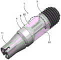
Fig. 1a shows a lighting module 1 for connection to a luminaire, of which only a lamp holder 11 is shown. Here, the lighting module 1 is shown as being mounted in a lamp socket 11. The lighting module 1 extends along a longitudinal axis LA, which extends through the center of the lamp base 11. The lighting module 1 includes:
a base (not shown) for connecting the lighting module to the lamp base 11 of the luminaire, which base is not visible in fig. 1a as being mounted inside the lamp base 11;
a central body 4 carrying a plurality of light sources 2, the plurality of light sources 2 comprising a first light source 21 and a second light source 22. The center body 4 includes a slender portion 41, a thick portion 42, a first connection portion 43a, and a second connection portion 43b. The slim portion 41 has a hexagonal shape. The connecting portions 43a, 43b have a truncated cone shape. Light sources 21 and 22 are attached to respective sides of slim portion 41, with slim portion 41 extending along longitudinal axis LA. The light source 2 of the accessory is attached to the remaining side of the slim portion 41. The base is connected to the thick portion 42 of the central body 4. The first connection portion 43a connects the thick portion 42 and the slim portion 41. The central body 4 further comprises a heat sink 5, the heat sink 5 being configured to transfer and dissipate heat from all light sources. The heat sink 5 is connected to the slim portion 41. The heat sink 5 has cooling fins positioned at opposite ends of the lighting module 1 along the longitudinal axis LA from the base. The slender portion 41 has a smaller diameter than both the thick portion 42 and the cooling fins of the heat sink 5.
The first light source 21 is configured to emit light having a first light distribution with a first main direction at an angle of 90 ° to the longitudinal axis LA. The second light source 22 is configured to emit light having a second light distribution with a second main direction at an angle of 90 ° to the longitudinal axis LA. The first main direction and the second main direction are different from each other. The light sources 21, 22 are each shown as being arranged in two rows of ten LEDs, with the row extending along the longitudinal axis. The LEDs of each light source have a light distribution with a main direction at an angle of 90 ° to the longitudinal axis LA. The main direction of the light source 2 coincides with the normal to the surface of the central body 4, the light source 2 being attached to the central body 4.
Fig. 1b shows the lighting module 1 of fig. 1a provided according to the invention, wherein the optical element 6 is rotatable about the longitudinal axis LA with respect to the central body 4. The optical element 6 comprises an optical portion 61 having reflective properties such that the optical portion 61 is configured to deflect light emitted from the at least one light source 2 in a plane perpendicular to the longitudinal axis LA. The optical portion 61 extends around the longitudinal axis in an angular region of about 60 °. In this embodiment, the optical portion 61 has a uniform cross-section along the longitudinal axis LA. The optical element 6 comprises a cover portion 62 adjacent to the optical portion 61. The optical element 6 (comprising the cover portion 62) extends around the periphery of the central body 4 in a plane perpendicular to the longitudinal axis.
Fig. 2a shows a lighting module 1, the lighting module 1 being mounted in a luminaire 10 provided with a lamp holder 11 and a reflector 12, wherein a longitudinal axis LA is oriented in a similar manner as in fig. 1 a. The longitudinal axis LA coincides with the optical center of the reflector 12.
Fig. 2b shows a schematic side view of the lighting module 1a, which is perpendicular to the longitudinal axis LA. The lighting module 1a comprises the same elements as mentioned in relation to the lighting module 1 shown in fig. 1, and the base 3 is shown connected to the thick portion 42 of the central body 4. However, in this embodiment only four light sources 2 are indicated along the periphery of the slim portion 41 (three light sources 21, 22, 23 are visible in the figure). Each of the light sources 2 is shown as comprising a row of eight sub-light sources 2' (not all identified with a reference numeral), here a single LED.
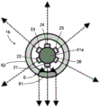
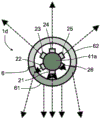
Fig. 3a shows a schematic cross-section of the lighting module 1b in a plane, which is shown as I-I in fig. 1a, and which is perpendicular to the longitudinal axis LA at the slim portion 41 of the central body 4. The lighting module 1b is similar to the lighting module 1 of fig. 1b, except that the slim portion 41a has a circular cross-section instead of a hexagonal cross-section. The slim section 41a carries six light sources 21, 22, 23, 24, 25, 26. The main direction of light for each light source is substantially perpendicular to the surface of the slim portion 41a at the plane where the respective light source is attached. The optical element 6 includes an optical portion 61 and a cover portion 62, and the optical element 6 extends around the periphery of the slim portion 41 of the center body 4. The optical portion 61 is positioned to deflect light emitted from the first light source 21. The deflected rays of light from the first light source 21 are parallel. The cover portion 62 does not substantially affect the emission of light from the remaining light sources 22, 23, 24, 25, 26.
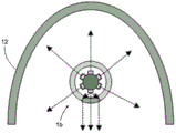
Fig. 3b schematically shows the lighting module 1b of fig. 3a, which lighting module 1b is mounted in a luminaire of which only the reflector 12 is shown. The lighting module 1b is mounted such that the longitudinal axis LA coincides with the optical center of the reflector 12.
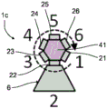
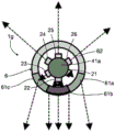
Fig. 4a shows a schematic cross section of a lighting module 1c. In this embodiment, the slim portion 41 of the central body 4 has a hexagonal cross-section of the embodiment of fig. 1a and 1b. The optical element 6 is rotatable about the longitudinal axis with respect to the central body 4, and the optical element 6 comprises one optical portion 61. The optical element 6 is positioned at a position where the optical portion 61 deflects the light emitted from the fourth light source 24.
Fig. 4b shows the same lighting module 1c as fig. 4a, but in comparison to fig. 4a the optical element 6 is rotated clockwise by 120 ° to a position in which the optical portion 61 deflects the light emitted from the second light source 22 instead of the light emitted from the fourth light source 24.
Fig. 4c shows a lighting module 1d similar to the lighting module 1b shown in fig. 3 a. However, in this embodiment shown in fig. 4c, the optical portion 61 of the optical element 6 extends in an angular region of about 150 °. The optical portion 61 has a deflection characteristic and a collimation characteristic such that the optical portion 61 is configured to deflect light emitted from two light sources of the six light sources (e.g., the second light source 22 and the sixth light source 26) and collimate light emitted from one light source of the six light sources (e.g., the first light source 21). In this arrangement, the deflected light of the second light source 22 and the sixth light source 26 is more nearly parallel after deflection relative to the light emitted from the first light source 21 than before deflection. The light emitted from the first light source 21 is collimated such that it is substantially parallel when it leaves the optical portion 61.
Fig. 4d shows a lighting module 1d' similar to the lighting module 1d shown in fig. 4 c. In this embodiment shown in fig. 4d, the optical portion 61 has a deflection characteristic and a collimation characteristic, such that the optical portion 61 is configured to deflect light emitted from one light source of the six light sources (e.g., the first light source 21) and collimate light emitted from two light sources of the six light sources (e.g., the second light source 21 and the sixth light source 26). In this arrangement, after being deflected by the optical portion 61, the light emitted from the first light source 21 is split into two directions, one of which is more or less parallel to the collimated light from the second light source 22 and the other of which is more or less parallel to the collimated light from the sixth light source 26.
Fig. 5a shows a lighting module 1e similar to fig. 4 a. In this embodiment, the optical element 6 includes: a first optical portion 61a, a second optical portion 61b, and a third optical portion 61c. Each of the optical portions 61a, 61b, 61c has a deflection characteristic such that each of the optical portions 61a, 61b, 61c is configured to deflect light emitted from one light source (e.g., the first light source 21, the second light source 22, and the third light source 26). Thus, the optical element 6 will deflect light from three of the six light sources.
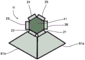
Fig. 5b shows a lighting module 1f similar to fig. 4 a. In this embodiment, the optical element 6 includes a first optical portion 61a and a second optical portion 61b. Each of the optical portions 61a, 61b has a deflection characteristic such that each of the optical portions 61a, 61b is configured to deflect light emitted from one light source (e.g., the first light source 21 and the second light source 22), respectively. Thus, in this embodiment, the optical element 6 will deflect light from two of the six light sources.
Fig. 6a shows a lighting module 1g similar to fig. 4 c. In this embodiment, the optical element 6 includes a first optical portion 61a, a second optical portion 61b, a third optical portion 61c, and a cover portion 62. Each optical portion 61a, 61b, 61c extends in an angular region of about 50 °. Each of the optical portions 61a, 61b, 61c has a deflection characteristic such that each of the optical portions is configured to deflect light emitted from one light source (e.g., the first light source 21, the second light source 22, and the third light source 26, respectively).
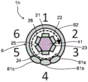
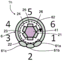
Fig. 6b shows a schematic cross section of a lighting module 1h similar to fig. 4 a. In this embodiment, the optical element 6 includes a first optical portion 61a, a second optical portion 61b, a third optical portion 61c, and a cover portion 62. Each optical portion 61a, 61b, 61c extends in an angular region of about 30 °. The optical element 6 is positioned in a position in which the optical portions 61a, 61b, 61c are configured to deflect light emitted from the fourth light source 24 and partially deflect light emitted from the third and fifth light sources 23, 25.
Fig. 6c shows the same lighting module 1h as fig. 6b, wherein the optical element 6 is rotated 120 ° clockwise into a position wherein the optical parts 61a, 61b, 61c are configured to deflect the light emitted from the second light source 22 and to partially deflect the light emitted from the first light source 21 and the third light source 23.
It should be understood that any one of the lighting modules 1a, 1b, 1c, 1d', 1e, 1f, 1g and 1h may be used as the module 1 in the luminaire 10 as shown in fig. 2a and indicated in fig. 3b or in another corresponding luminaire. The latter shows the lighting module 1 in a position in which the longitudinal axis is horizontal, and the luminaire is positioned to emit light downwards. When the optical element 6 has a center of gravity displaced from the longitudinal axis LA and the optical element 6 is mounted in a loose fit, gravity may rotate the optical element 6 about the longitudinal axis LA to the position shown in fig. 3a and 3b to 6a to 6 c.
The lamp 10 shown in fig. 2a may be a lamp configured for use with, for example, a High Pressure Sodium (HPS) arc lamp. The lighting modules 1-1h may be used for retrofitting in the luminaire 10, whereby the rotational orientation of the lighting modules may be unknown after installation in the lamp holder 11. The light distribution of the light source 2 carried by the central body 4 will be different from the light distribution of the light source of the gas discharge lamp for which the luminaire 10 is designed, so that the light distribution of the lighting module 1 will not match the light distribution of the luminaire 10 being constructed. According to the invention, this mismatch is compensated by the optical element 6, which optical element 6 is rotatable about the longitudinal axis LA to be correctly positioned in the luminaire 10 with respect to the position of the lighting module 1. The rotation of the optical element 6 into its correct position may be achieved by gravity as described above, or may be done manually after mounting the lighting module 1 in the luminaire 10, and there may be measures for fixing the optical element 6 to the central body 4 to avoid an unintentional rotation of the optical element 6 from the intended position.
List of reference numerals
1. 1a, 1b, 1c, 1d', 1e, 1f, 1g, 1h lighting module
2. Light source
21. First light source
22. Second light source
23. Third light source
24. Fourth light source
25. Fifth light source
26. Sixth light source
2' sub-light source
3. Base seat
31. Base end
4. Center body
41. 41a slender portion
42. Thick portion
43. Connection part
5. Heat sink
6. Optical element
61. Optical part
62. Cover part
LA longitudinal axis
10. Lamp set
11. Lamp holder
12. Reflector
Claims (15)
1. A lighting module (1) extending along a Longitudinal Axis (LA) and configured for connection to a luminaire providing a light distribution remote from the longitudinal axis, and comprising:
a base for connecting the lighting module to a socket of the luminaire;
a central body (4), said central body (4) carrying at least a first light source (21) and a second light source (22),
wherein the first light source (21) is configured to emit first light having a first light distribution with a first main direction pointing away from the longitudinal axis; and the second light source (22) is configured to emit second light having a second light distribution with a second main direction pointing away from the longitudinal axis, the first and second main directions being different from each other; and
-an optical element (6), the optical element (6) comprising a cover portion (62) extending around the circumference of the central body (4) and at least one optical portion (61), and the optical element (6) being rotatable about the Longitudinal Axis (LA) with respect to the central body (4), the at least one optical portion (61) having optical properties such that the optical portion (61) is configured to influence light emitted from at least one of the first light source (21) and the second light source (22), the at least one optical portion (61) extending in an angular region about the longitudinal axis, and the cover portion (62) being configured not to influence light emitted from the remaining one of the first light source (21) and the second light source (22).
2. The lighting module of claim 1, wherein the optical element comprises a plurality of optical portions, each optical portion extending in a different angular region about the longitudinal axis, and each optical portion having at least one optical characteristic.
3. The lighting module of any one of the preceding claims, wherein each optical portion of the optical element has at least one optical characteristic selected from the group consisting of: collimation, refraction, reflection, transparency, translucency, deflection and diffraction.
4. The lighting module of claim 1 or 2, wherein the at least one optical characteristic of each optical portion is different from each other.
5. The lighting module of claim 1 or 2, the cover portion being positioned adjacent to the optical portion and extending in a second angular region about the longitudinal axis.
6. A lighting module according to claim 1 or 2, wherein the optical element comprising the cover portion extends around the periphery of the central body in a plane perpendicular to the longitudinal axis.
7. The lighting module according to claim 1 or 2, wherein the first main direction of the first light emitted from the first light source (21) and the second main direction of the second light emitted from the second light source (22) are in a plane perpendicular to the longitudinal axis.
8. The lighting module of claim 1 or 2, wherein the central body comprises a heat sink configured to transfer and dissipate heat from the first light source (21) and the second light source (22).
9. The lighting module according to claim 1 or 2, wherein the first light source (21) and the second light source (22) are positioned at a distance from the longitudinal axis, the distance being smaller than a maximum outer diameter of the central body.
10. The lighting module of claim 1 or 2, wherein the lighting module is configured to allow fixing of the orientation of the optical element with respect to the central body.
11. A lighting module according to claim 1 or 2, comprising a number of light sources, each light source emitting light with a different main direction, the number being selected from the group consisting of: 3. 4, 5 and 6.
12. A lighting module according to claim 1 or 2, wherein the optical element has a centre of gravity displaced from the longitudinal axis, and the optical element is mounted in a loose fit, allowing gravity to rotate the optical element about the longitudinal axis when the lighting module is in a position in which the longitudinal axis is not vertical.
13. The lighting module of claim 1 or 2, wherein the optical portion is configured to collimate light in a plane perpendicular to the longitudinal axis.
14. A luminaire, comprising: a lamp socket and a lighting module according to any one of the preceding claims, wherein the lighting module is connected to the lamp socket.
15. A method for mounting a lighting module according to any one of claims 1 to 13 in a luminaire, comprising the steps of:
providing a luminaire having a lamp holder and a lighting module according to any one of claims 1 to 13,
connecting the base of the lighting module to the lamp socket,
by rotating the optical element about the longitudinal axis, the angular orientation of the optical element with respect to the central body is adjusted to provide a desired light distribution,
and optionally fixing an orientation of the optical element relative to the central body.
Applications Claiming Priority (3)
| Application Number | Priority Date | Filing Date | Title |
|---|---|---|---|
| EP17182265 | 2017-07-20 | ||
| EP17182265.3 | 2017-07-20 | ||
| PCT/EP2018/069290 WO2019016150A1 (en) | 2017-07-20 | 2018-07-16 | Lighting module |
Publications (2)
| Publication Number | Publication Date |
|---|---|
| CN110959089A CN110959089A (en) | 2020-04-03 |
| CN110959089B true CN110959089B (en) | 2023-06-16 |
Family
ID=59383987
Family Applications (1)
| Application Number | Title | Priority Date | Filing Date |
|---|---|---|---|
| CN201880048367.7A Active CN110959089B (en) | 2017-07-20 | 2018-07-16 | Lighting module |
Country Status (5)
| Country | Link |
|---|---|
| US (1) | US10941906B2 (en) |
| EP (1) | EP3655695B1 (en) |
| JP (1) | JP6731567B1 (en) |
| CN (1) | CN110959089B (en) |
| WO (1) | WO2019016150A1 (en) |
Citations (1)
| Publication number | Priority date | Publication date | Assignee | Title |
|---|---|---|---|---|
| CN101893173A (en) * | 2009-05-20 | 2010-11-24 | 富士迈半导体精密工业(上海)有限公司 | Illuminating system |
Family Cites Families (31)
| Publication number | Priority date | Publication date | Assignee | Title |
|---|---|---|---|---|
| CN2394094Y (en) * | 1999-11-08 | 2000-08-30 | 俞志龙 | Height adjustable mark bulb |
| US6682211B2 (en) * | 2001-09-28 | 2004-01-27 | Osram Sylvania Inc. | Replaceable LED lamp capsule |
| DK1568254T3 (en) | 2002-11-19 | 2008-06-23 | Dan Friis | Light system or light source based on LEDs |
| JP2004296249A (en) | 2003-03-26 | 2004-10-21 | Matsushita Electric Works Ltd | Luminaire |
| JP2009016058A (en) * | 2007-06-29 | 2009-01-22 | Toshiba Lighting & Technology Corp | Illumination device, and illumination fixture using this |
| JP2009106258A (en) | 2007-10-12 | 2009-05-21 | Nippon Steel Engineering Co Ltd | Method for producing ethanol |
| US20090168425A1 (en) * | 2007-12-30 | 2009-07-02 | Ming-Chih Chuang | Bulb with rotating light effect |
| DE102009006185A1 (en) * | 2009-01-27 | 2010-07-29 | Osram Opto Semiconductors Gmbh | Lamp |
| GB2469790A (en) * | 2009-04-22 | 2010-11-03 | Keith Hannam | Coloured LED bulb with collimators |
| KR100968270B1 (en) | 2009-09-11 | 2010-07-06 | (주)엠이씨 | The led lamp |
| JP5330944B2 (en) * | 2009-09-18 | 2013-10-30 | パナソニック株式会社 | Light emitting device |
| DE102010003123A1 (en) * | 2010-03-22 | 2011-09-22 | Osram Gesellschaft mit beschränkter Haftung | Lamp with reflector means and reflector element |
| JP2012015012A (en) * | 2010-07-02 | 2012-01-19 | Idec Corp | Led lighting device |
| US8403509B2 (en) | 2010-10-05 | 2013-03-26 | Hua-Chun Chin | LED lamp whose lighting direction can be adjusted easily and quickly |
| TW201248083A (en) * | 2011-03-17 | 2012-12-01 | Rambus Inc | Adjustable light source, and light bulb with adjustable light source |
| US8657464B2 (en) | 2011-11-02 | 2014-02-25 | Honeywell International Inc. | Multiple mode light emitting device |
| CN103225749A (en) * | 2012-01-30 | 2013-07-31 | 欧司朗股份有限公司 | Led lamp tube |
| US8979347B2 (en) * | 2012-04-24 | 2015-03-17 | Qualcomm Mems Technologies, Inc. | Illumination systems and methods |
| US8919994B2 (en) * | 2012-12-12 | 2014-12-30 | Randal L. Wimberly | Illumination system and lamp utilizing directionalized LEDs |
| US9217546B2 (en) * | 2013-01-11 | 2015-12-22 | Wen-Sung Hu | LED bulb laterally installed and projecting light beams onto ground |
| WO2014121071A1 (en) * | 2013-01-31 | 2014-08-07 | Vamberi Gabor | Method and apparatus for rotational adjustable optics |
| JP6063301B2 (en) * | 2013-02-28 | 2017-01-18 | 株式会社東芝 | Lighting device |
| US8899794B2 (en) * | 2013-03-15 | 2014-12-02 | Bby Solutions, Inc. | LED bulb optical system with uniform light distribution |
| US8967837B2 (en) * | 2013-08-01 | 2015-03-03 | 3M Innovative Properties Company | Solid state light with features for controlling light distribution and air cooling channels |
| WO2015033296A1 (en) * | 2013-09-09 | 2015-03-12 | Koninklijke Philips N.V. | Luminaire with selectable emission pattern |
| DE102013226419A1 (en) | 2013-12-18 | 2015-06-18 | Zumtobel Lighting Gmbh | Lighting arrangement with at least two optical elements |
| US20150241042A1 (en) | 2014-02-27 | 2015-08-27 | QTOP USA, Inc. | Pivotable LED Light Bulb Apparatus |
| US20160230938A1 (en) * | 2015-02-10 | 2016-08-11 | Crownmate Technology Co., Ltd. | Omnidirectional light-emitting diode light bulb |
| US20200248893A1 (en) * | 2015-11-12 | 2020-08-06 | Ki Ho Jeon | Led lamp |
| US10323833B2 (en) * | 2016-10-11 | 2019-06-18 | Hall Labs Llc | Light bulb with a rotating base |
| US9989219B2 (en) * | 2016-10-14 | 2018-06-05 | David R. Hall | Light bulb with a motor |
-
2018
- 2018-07-16 CN CN201880048367.7A patent/CN110959089B/en active Active
- 2018-07-16 EP EP18738350.0A patent/EP3655695B1/en active Active
- 2018-07-16 US US16/632,364 patent/US10941906B2/en active Active
- 2018-07-16 JP JP2020502444A patent/JP6731567B1/en active Active
- 2018-07-16 WO PCT/EP2018/069290 patent/WO2019016150A1/en unknown
Patent Citations (1)
| Publication number | Priority date | Publication date | Assignee | Title |
|---|---|---|---|---|
| CN101893173A (en) * | 2009-05-20 | 2010-11-24 | 富士迈半导体精密工业(上海)有限公司 | Illuminating system |
Also Published As
| Publication number | Publication date |
|---|---|
| US10941906B2 (en) | 2021-03-09 |
| EP3655695A1 (en) | 2020-05-27 |
| JP2020526901A (en) | 2020-08-31 |
| WO2019016150A1 (en) | 2019-01-24 |
| EP3655695B1 (en) | 2020-11-11 |
| US20200208789A1 (en) | 2020-07-02 |
| JP6731567B1 (en) | 2020-07-29 |
| CN110959089A (en) | 2020-04-03 |
Similar Documents
| Publication | Publication Date | Title |
|---|---|---|
| CN101315165B (en) | Illuminating apparatus | |
| KR101209696B1 (en) | Led light system | |
| US9470371B2 (en) | Light unit with light output pattern synthesized from multiple light sources | |
| EP2557360B1 (en) | Led street light | |
| US8167462B2 (en) | Illumination lens and illumination unit including the same | |
| US20130141908A1 (en) | Miniature cellular structure for retrofit led lamp secondary optics | |
| US8579470B1 (en) | LED illumination source with improved visual characteristics | |
| US20090268453A1 (en) | LED baffle assembly | |
| JP2012501001A (en) | Directional circular reflector with equilateral triangular prism and disk-shaped light having the same | |
| CN102257316A (en) | Led street lamp | |
| KR100856725B1 (en) | Street lamp using led | |
| US20120162985A1 (en) | Solid state lighting unit incorporating optical spreading elements | |
| WO2014011665A1 (en) | Light unit with light output pattern synthesized from multiple light sources and modular refractors | |
| US20120051055A1 (en) | Retrofit system for converting an existing luminaire into a solid state lighting luminaire | |
| JP6818180B2 (en) | Lighting module | |
| CN110959089B (en) | Lighting module | |
| JP5676822B2 (en) | Street lamp lighting device | |
| KR101282128B1 (en) | LED lamp with reflector | |
| KR100395674B1 (en) | The traffic led lights arrayed lighting emitting diodes for hexagon | |
| WO2024175394A1 (en) | Led filament lamp | |
| KR200247858Y1 (en) | The traffic lights arrayed lighting emitting diodes for hexagon | |
| KR101083431B1 (en) | Lighting apparatus for street lamp | |
| KR20180137843A (en) | Lighting apparatus with light-diffusing function |
Legal Events
| Date | Code | Title | Description |
|---|---|---|---|
| PB01 | Publication | ||
| PB01 | Publication | ||
| SE01 | Entry into force of request for substantive examination | ||
| SE01 | Entry into force of request for substantive examination | ||
| GR01 | Patent grant | ||
| GR01 | Patent grant |