JP5524448B2 - elevator - Google Patents
elevator Download PDFInfo
- Publication number
- JP5524448B2 JP5524448B2 JP2007523091A JP2007523091A JP5524448B2 JP 5524448 B2 JP5524448 B2 JP 5524448B2 JP 2007523091 A JP2007523091 A JP 2007523091A JP 2007523091 A JP2007523091 A JP 2007523091A JP 5524448 B2 JP5524448 B2 JP 5524448B2
- Authority
- JP
- Japan
- Prior art keywords
- elevator
- rope
- car
- elevator car
- brake
- Prior art date
- Legal status (The legal status is an assumption and is not a legal conclusion. Google has not performed a legal analysis and makes no representation as to the accuracy of the status listed.)
- Expired - Fee Related
Links
Images


Classifications
-
- B—PERFORMING OPERATIONS; TRANSPORTING
- B66—HOISTING; LIFTING; HAULING
- B66B—ELEVATORS; ESCALATORS OR MOVING WALKWAYS
- B66B5/00—Applications of checking, fault-correcting, or safety devices in elevators
- B66B5/02—Applications of checking, fault-correcting, or safety devices in elevators responsive to abnormal operating conditions
- B66B5/04—Applications of checking, fault-correcting, or safety devices in elevators responsive to abnormal operating conditions for detecting excessive speed
-
- B—PERFORMING OPERATIONS; TRANSPORTING
- B66—HOISTING; LIFTING; HAULING
- B66B—ELEVATORS; ESCALATORS OR MOVING WALKWAYS
- B66B11/00—Main component parts of lifts in, or associated with, buildings or other structures
- B66B11/04—Driving gear ; Details thereof, e.g. seals
- B66B11/08—Driving gear ; Details thereof, e.g. seals with hoisting rope or cable operated by frictional engagement with a winding drum or sheave
-
- B—PERFORMING OPERATIONS; TRANSPORTING
- B66—HOISTING; LIFTING; HAULING
- B66B—ELEVATORS; ESCALATORS OR MOVING WALKWAYS
- B66B5/00—Applications of checking, fault-correcting, or safety devices in elevators
- B66B5/02—Applications of checking, fault-correcting, or safety devices in elevators responsive to abnormal operating conditions
- B66B5/16—Braking or catch devices operating between cars, cages, or skips and fixed guide elements or surfaces in hoistway or well
- B66B5/18—Braking or catch devices operating between cars, cages, or skips and fixed guide elements or surfaces in hoistway or well and applying frictional retarding forces
Description
本発明は、請求項1の前段に記載のエレベータと、請求項10の前段に記載のトラクションシーブエレベータの制動方法に関するものである。
The present invention relates to an elevator according to the first stage of
エレベータ開発作業における目的の1つは、建物の空間の効率的および経済的な利用を実現することにある。近年では、この開発作業は、なかでも、さまざまな機械室のないエレベータ方式を生み出している。機械室のないエレベータの好適な例は、欧州特許出願公開第EP0631967(A1)号、および欧州特許出願公開第EP0631968号の明細書に開示されている。これらの明細書に記載されたエレベータは、空間利用に関してかなり効率的であり、エレベータシャフトを大型にしなくても、建物においてエレベータ機械室に必要な空間を除去することができる。これらの明細書に開示されたエレベータにおいて、少なくとも一方では機械がコンパクトであるが、他方では従来のエレベータ機械よりもかなり大きな寸法を有することがあり得る。 One of the goals in elevator development work is to achieve efficient and economical use of building space. In recent years, this development work has produced, among other things, an elevator system without various machine rooms. Suitable examples of elevators without a machine room are disclosed in the specifications of EP 0631967 (A1) and EP 0631968. The elevators described in these specifications are fairly efficient in terms of space utilization and can eliminate the space required for the elevator machine room in a building without the need for a large elevator shaft. In the elevators disclosed in these specifications, the machine is compact at least on the one hand, but on the other hand it can have significantly larger dimensions than conventional elevator machines.
これらの基本的に良好なエレベータ方式においては、巻上機に必要な空間がエレベータレイアウト方式の選択の自由を制限している。空間は巻上ロープの走路に要する設備にとって必要である。少なくとも妥当な費用で、かつエレベータの性能および作動品質を損なうことなく、エレベータかご自身の軌道に必要な空間、および釣合重りに必要な空間を小さくすることは困難である。機械室のないトラクションシーブエレベータでは、エレベータシャフトに巻上機を取り付けることが、とくに上方に機械を有する方式においてしばしば困難である。なぜならば、巻上機は、かなりの重量の相当に大きな物体であるからである。とくに、荷重、速度および/または走行高さが大きい場合、機械の大きさおよび重量が、設置に関する問題であり、必要な機械の大きさおよび重量が、実際では機械室のないエレベータの概念の適用範囲を制限し、あるいは少なくとも大きなエレベータにおけるこの概念の導入を遅らせてしまうほどである。エレベータの近代化において、エレベータシャフト内に利用可能な空間は、機械室のないエレベータの概念の適用範囲をしばしば制限する。米国特許第5788018号には、従来技術の1つの方式が開示され、ここでは、エレベータかごが1:1の懸垂比で懸垂され、さらにさまざまな引張装置が用いられて連続した巻上ロープを引っ張っている。この公報に記載された補正シーブは別個の制御システムによって調整され、このシステムは外部制御装置によって制御され、すなわち複合外部制御装置によって行われる制御を必要とする。最近の釣合重りのないトラクションシーブエレベータ方式として、国際出願公開第2004041704号が実行可能な方式を提供している。そこでは、エレベータにおけるエレベータかごの動きは、トラクションシーブによるエレベータの巻上ロープからのトラクション摩擦に基づいている。このエレベータ方式は主な対象として、走行高さが低く、背の低い建物および/または複数の建物を挙げている。この公報で解決されている問題は、主に、比較的低い建物における使用に適用可能であるが、この概念をより走行高さが高くて速度が速いものに適用すると、解決すべき新しい問題がもたらされる。釣合重りのない従来技術のエレベータ方式において、巻上ロープの引張は重りまたはバネによって行われるが、これは巻上ロープの引張を行うには魅力的な手段ではない。また釣合重りのないエレベータ方式に関する他の問題は、たとえば長いロープが、たとえば走行高さが高いビルまたは高層ビル、および/または大きな懸垂比によるロープ長のために用いられる場合の、ロープの伸張の補正であり、さらに、ロープの伸張のために、トラクションシーブと巻上ロープとの間の摩擦がエレベータの運行に不十分なことである。 In these basically good elevator systems, the space required for the hoisting machine limits the choice of elevator layout system. Space is necessary for the equipment required for the hoisting rope track. It is difficult to reduce the space required for the elevator car's own track and the space required for the counterweight, at least at a reasonable cost and without compromising the performance and operating quality of the elevator. In a traction sheave elevator without a machine room, it is often difficult to attach the hoist to the elevator shaft, especially in the system with the machine above. This is because the hoist is a fairly large object with a considerable weight. Especially when loads, speeds and / or travel heights are large, the size and weight of the machine is a matter of installation, and the required size and weight of the machine is an application of the concept of an elevator without a machine room. It limits the range, or at least delays the introduction of this concept in large elevators. In elevator modernization, the space available in the elevator shaft often limits the scope of the elevator concept without a machine room. U.S. Pat. No. 5,780,018 discloses one prior art system in which an elevator car is suspended with a 1: 1 suspension ratio and various tensioning devices are used to pull a continuous hoisting rope. ing. The correction sheave described in this publication is regulated by a separate control system, which is controlled by an external controller, i.e. requires control performed by a complex external controller. As a recent traction sheave elevator system without a balance weight, a system capable of executing International Application Publication No. 2004041704 is provided. There, the movement of the elevator car in the elevator is based on the traction friction from the hoisting rope of the elevator by the traction sheave. This elevator system is mainly intended for buildings and / or buildings with low running height and low height. The problem solved in this publication is mainly applicable for use in relatively low buildings, but applying this concept to higher travel speeds and faster speeds creates new problems to be solved. Brought about. In prior art elevator systems without a counterweight, the hoisting rope tension is effected by a weight or a spring, which is not an attractive means for tensioning the hoisting rope. Other problems with elevator systems without counterweights are, for example, rope stretch when long ropes are used for high travel or high-rise buildings and / or rope lengths with high suspension ratios, for example. Furthermore, due to the extension of the rope, the friction between the traction sheave and the hoisting rope is insufficient for the operation of the elevator.
本発明は、次の目的のうち少なくとも1つを達成することを目的とする。一方において、本発明は、機械室なしのエレベータを開発して、さらに建物およびエレベータシャフトにおける以前よりも効果的な空間利用を可能にすることを目的とする。これは、必要であれば、エレベータをかなり狭いエレベータシャフトに設置することを可能にするべきであることを意味している。巻上ロープがトラクションシーブ上に十分に把持/接触をするエレベータを実現することを1つの目的とする。さらに本発明は、釣合重りのないエレベータ方式をエレベータの特性を落とさずに実現することを目的とする。また本発明は、ロープの伸張を除去することを目的とする。さらに、本発明は、エレベータを実現し、それによって高層ビルにおける釣合重りのないエレベータおよび/または釣合重りのない高速エレベータを実行可能にすることを目的とする。また、緊急停止の場合、とくにエレベータかごが上昇している間にエレベータの緊急停止が行われる場合に安全なエレベータを提供することを目的とする。 The present invention aims to achieve at least one of the following objects. On the one hand, the present invention aims to develop elevators without machine rooms and to allow more efficient space utilization in buildings and elevator shafts than before. This means that if necessary, it should be possible to install the elevator on a fairly narrow elevator shaft. One object is to realize an elevator in which the hoisting rope is sufficiently gripped / contacted on the traction sheave. A further object of the present invention is to realize an elevator system without a counterweight without degrading the characteristics of the elevator. Another object of the present invention is to remove the extension of the rope. Furthermore, the invention aims to realize an elevator, thereby enabling an unbalanced elevator and / or unbalanced high-speed elevator in a high-rise building. It is another object of the present invention to provide a safe elevator in the case of an emergency stop, particularly when an emergency stop of the elevator is performed while the elevator car is moving up.
本発明の目的は、基本的なエレベータの設計を変えることなく達成される必要がある。 The objectives of the present invention need to be achieved without changing the basic elevator design.
本発明のエレベータは、請求項1の特徴段に開示した事項を特徴とし、本発明の方法は請求項10の特徴段に開示した事項を特徴とをする。本発明の他の実施例は、その他の請求項に開示した事項を特徴とする。また本発明のいくつかの実施例を本願の詳細な説明部分に示す。本願の発明内容を上記請求項に定義したもの以外の方法でも定義することができる。本発明内容はまた、とくに本発明を表現もしくは内在する従属課題に照らして、または達成される利点もしくは一連の利点の観点から考慮した場合、いくつかの別の発明で構成することもできる。この場合、上記特許請求の範囲に含まれる属性のいくつかは、別の発明概念については不要になるとことがある。本発明のさまざまな実施例、および実施例における特徴ならびに細部は、互いに関連して適用し得る。
The elevator of the invention is characterized by what is disclosed in the characterizing stage of
本発明を適用することにより、なかでも、次の利点を達成することができる:
− 本発明のエレベータは緊急制動の場合、とくにエレベータの上昇中に制動をかけた場合においても安全である。
− 本発明による制動動作は、制御構造およびブレーキ構造の両方によって容易に実行可能である。
− エレベータかごが上昇中の緊急状況での制動動作は、ブレーキ構造および制御装置によって阻止される。
− ブレーキの制御は、エレベータへの給電障害がある場合でも予備電力によって可能である。
− この制動機能は、高層ビルでの使用に、および釣合重りのない高速エレベータに適用することができる。
− 上昇方向での制動を行う場合のブレーキ係合の遅れを容易に一定にすることができ、または遅れをエレベータの速度に応じて容易に設定することができる。
By applying the present invention, among other things, the following advantages can be achieved:
The elevator according to the invention is safe even in emergency braking, in particular when braking is applied while the elevator is moving up.
The braking operation according to the invention can easily be carried out by both the control structure and the brake structure;
Braking action in an emergency situation when the elevator car is rising is blocked by the brake structure and the control device.
-Brake control is possible with reserve power even when there is a power failure to the elevator.
-This braking function can be applied for use in high-rise buildings and in high speed elevators without balancing weights.
The delay in brake engagement when braking in the ascending direction can be made constant easily, or the delay can be easily set according to the speed of the elevator.
本発明の主たる適用分野は、人および/または貨物の輸送用に設計されたエレベータである。本発明の通常の適用分野は、速度範囲が約1m/sより速いエレベータにあるが、1.0 m/sよりも遅いこともある。たとえば、6m/sの走行速度のエレベータおよび/または0.6 m/sの走行速度のエレベータは、本発明による実行が容易である。本発明によるエレベータは、機械室付きおよび機械室なしの両方のエレベータ方式において、高層および超高層の建物での使用に適用することもできる。また、本発明によるエレベータによって、高速エレベータ方式を実行することもできる。 The main field of application of the present invention is elevators designed for the transport of people and / or cargo. A typical field of application of the invention is in elevators where the speed range is faster than about 1 m / s, but may be slower than 1.0 m / s. For example, an elevator with a traveling speed of 6 m / s and / or an elevator with a traveling speed of 0.6 m / s is easy to implement according to the invention. The elevator according to the invention can also be applied for use in high-rise and high-rise buildings in both machine room and machine room elevator systems. The elevator according to the present invention can also implement a high speed elevator system.
乗客および貨物用の両方のエレベータにおいて、本発明により達成される利点の多くは、2〜4名用のエレベータにおいても明確に発揮され、6〜8名用(500〜630 kg)のエレベータにおいても発揮される。 Many of the advantages achieved by the present invention in both passenger and cargo elevators are clearly demonstrated in elevators for 2 to 4 people, and even in elevators for 6 to 8 people (500 to 630 kg). Demonstrated.
本発明のエレベータにおいて、一般的に使用されている鋼鉄製ロープなどの通常のエレベータ巻上ロープを適用することができる。本エレベータでは、最近エレベータにおける使用に提案されている、たとえばいわゆる「アラミドロープ」などの、人造材料で作られたロープ、および人造繊維で荷重支持部が作られているロープを用いることができる。また適用可能な方式には、鋼鉄強化平ロープも含まれる。なぜならば、とくにたわみ半径を小さくすることができるからである。本発明のエレベータにおいてとくに適合可能なものは、たとえば丸く強力なワイヤを撚り合わせたエレベータ巻上ロープである。丸いワイヤからは、異なる太さまたは同じ太さのワイヤを用いて多くの方法でロープを撚ることができる。また、本発明のエレベータでは、従来のエレベータの巻上ロープを使用することが可能である。たとえば懸垂比が2:1、走行速度が約6 m/s、およびかごと最大荷重との質量が約4000 kgであるエレベータにおいては、それぞれの直径が13mmの6本の巻上ロープだけを必要とする。2:1の懸垂比である本発明によるエレベータの望ましい適用分野は、速度が約4 m/s以上の範囲のエレベータである。本発明のエレベータにおける1つの設計基準では、ロープ速度を20 m/s以下に保っている。ロープ速度が約10 m/sの場合では、エレベータの速度範囲は1つであり、その範囲におけるエレベータのトラクションシーブ上でのロープの作用および動きがかなりよく知られている。本発明のエレベータの好ましい方式は機械室なしのエレベータであるが、さらに機械付きの方式を本発明によって容易に実現できる。高層ビルにおいて、機械室がないことは必ずしも重要なことではないが、本発明によるエレベータによって、10〜20%あるいはそれ以上のシャフト空間の節減が実現できる。すなわち、建物の表面積に利用においいてとても大きな利点が達成される。 In the elevator of the present invention, an ordinary elevator hoisting rope such as a steel rope that is generally used can be applied. In this elevator, it is possible to use a rope made of an artificial material, such as a so-called “aramid rope”, which has recently been proposed for use in an elevator, and a rope having a load support made of an artificial fiber. Applicable methods also include steel reinforced flat ropes. This is because the deflection radius can be particularly reduced. Particularly applicable in the elevator of the present invention is, for example, an elevator hoisting rope formed by twisting round and strong wires. From a round wire, the rope can be twisted in a number of ways using wires of different or the same thickness. In the elevator of the present invention, a conventional elevator hoisting rope can be used. For example, an elevator with a suspension ratio of 2: 1, a running speed of about 6 m / s, and a mass with a car and maximum load of about 4000 kg requires only six hoists with a diameter of 13 mm each. And A preferred field of application of the elevator according to the invention with a 2: 1 suspension ratio is an elevator with a speed in the range of about 4 m / s or more. One design criterion for the elevator of the present invention is to keep the rope speed below 20 m / s. When the rope speed is about 10 m / s, there is one elevator speed range, and the action and movement of the rope on the elevator traction sheave in that range is fairly well known. Although the preferred system of the elevator of the present invention is an elevator without a machine room, a system with a machine can be easily realized by the present invention. In high-rise buildings, the absence of a machine room is not necessarily important, but an elevator according to the present invention can achieve a shaft space saving of 10-20% or more. That is, a great advantage is achieved in the use of the building surface area.
本発明による釣合重りのないエレベータの好ましい実施例では、たとえば4:1の懸垂比で、直径8 mmの従来のエレベータ巻上ロープが使用され、3 m/sのエレベータ速度で、およびエレベータかごと最大荷重との重量が4000 kgであり、このような場合、8本の巻上ロープしか必要ではない。他の好ましい実施例では、釣合重りのないエレベータは、懸垂比が6:1で、速度が1.6 m/sで、直径8mmの従来のロープが使用され、およびエレベータのエレベータかごと最大荷重との質量が最大3400 kgであり、このような場合、5本のロープしか必要としない。 In a preferred embodiment of the unweighted elevator according to the invention, a conventional elevator hoisting rope with a diameter of 8 mm, for example with a suspension ratio of 4: 1 is used, at an elevator speed of 3 m / s and in the elevator car And the maximum load weight is 4000 kg, in which case only 8 hoisting ropes are needed. In another preferred embodiment, an unbalanced elevator uses a conventional rope with a suspension ratio of 6: 1, a speed of 1.6 m / s, a diameter of 8 mm, and the elevator car and maximum load. The maximum mass is 3400 kg, and in such a case only 5 ropes are needed.
釣合重りのないトラクションシーブエレベータが上昇中の場合、緊急停止の際にブレーキがかかると、ブレーキが極端に早くかかる。なぜならば、移動質量が正味の減速力に対してかなり小さいからである。かごの減速には重力が関与するが、釣合重りにより生じる反対方向の力係数は存在しない。とくに高速で生じる緊急停止において、乗客に対する減速力の影響期間は、乗客の“軽減感”がたとえば乗客に対する傷害などの重大な結果になり得る。どんな場合においても極端な減速は殆どの人に対して不快な感じを与える。最悪の場合、摩擦および制動により生じるかごのさらなる減速はかごの減速力を重力gよりも大きくし、この場合に自身への重力による作用だけで減速している乗客が、かごの床から離れてしまう。したがって本発明は、エレベータ全体の重力gよりもかなり小さい減速をすべての起こりえる状況で実現することを1つの目的とする。 When a traction sheave elevator without a counterweight is moving up, if the brake is applied during an emergency stop, the brake is applied extremely quickly. This is because the moving mass is much smaller than the net deceleration force. Although the car is slowed down by gravity, there is no force factor in the opposite direction caused by the counterweight. Especially in emergency stops that occur at high speeds, the period of influence of the deceleration force on the passenger can cause a serious “feeling of mitigation” of the passenger, for example injury to the passenger. In any case, extreme slowdowns are uncomfortable for most people. In the worst case, further deceleration of the car caused by friction and braking causes the car's deceleration force to be greater than the gravitational force g, in which case a passenger who is decelerating only by the action of gravity on himself is moving away from the car floor. End up. The present invention therefore has as an object the realization of a deceleration which is considerably smaller than the gravity g of the entire elevator in all possible situations.
問題は、緊急停止が発生した場合、本発明による釣合重りのないエレベータでは、かごの上昇移動中に制御装置がブレーキの係合を妨げてかごを制動することによって解決される。作動ブレーキの制御は予備電力によって維持される。他の案は、エレベータ用の把持ブレーキを構造的に形成することであり、これは実質的にエレベータかごの下降の動きだけを留めるよう設計される。把持ブレーキによる制動力は、上昇運動方向の場合では、下降運動方向の場合よりもかなり小さく、またはほとんどないこともある。かごの質量に対して巻上ロープの質量が大きいほど、エレベータかごの減速力は小さくなる。したがって、走行高さが高いエレベータはもともと速いので、その減速度は遅くなる。 The problem is solved in the event of an emergency stop, in an elevator with no counterweight according to the invention, where the control device brakes the car by preventing the brakes from engaging during the upward movement of the car. Control of the operating brake is maintained by reserve power. Another idea is to structurally form a grip brake for the elevator, which is designed to substantially only keep the elevator car descending. The braking force by the gripping brake may be much smaller or little in the upward movement direction than in the downward movement direction. The greater the mass of the hoisting rope with respect to the mass of the car, the smaller the deceleration force of the elevator car. Therefore, an elevator with a high traveling height is originally fast, and its deceleration is slow.
本発明の釣合重りのないトラクションシーブエレベータでは、エレベータかごは1本のロープまたは複数のロープから成る巻上ロープによってエレベータ内で懸垂される。このエレベータはトラクションシーブを有し、これは巻上ロープによってエレベータかごを動かす。緊急停止の際にエレベータかごがエレベータ内で上昇移動している場合では、エレベータの作動ブレーキによる制動は、エレベータの停止距離の少なくとも一部の間で少なくとも部分的に阻止される。 In the unbalanced traction sheave elevator of the present invention, the elevator car is suspended in the elevator by a hoisting rope consisting of a single rope or a plurality of ropes. This elevator has a traction sheave which moves the elevator car by means of a hoisting rope. If the elevator car is moving up in the elevator during an emergency stop, braking by the elevator operating brake is at least partially blocked during at least a portion of the elevator stopping distance.
釣合重りのないトラクションシーブエレベータを制動する本発明による方法において、制動は、緊急停止の際にエレベータかごが上昇移動している場合では、エレベータの作動ブレーキによる制動がエレベータの停止距離の少なくとも一部の間で少なくとも部分的に阻止されることによって行われる。 In the method according to the invention for braking a traction sheave elevator without a counterweight, the braking is carried out when the elevator car is moving up during an emergency stop, and the braking by the elevator operating brake is at least one of the elevator stopping distances. This is done by being at least partly blocked between the parts.
次に、いくつかの実施例および添付の図面を参照して、本発明を詳細に説明する。 The present invention will now be described in detail with reference to a few examples and the accompanying drawings.
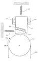
図1は、本発明による釣合重りのないトラクションシーブエレベータの概略図である。本発明による補正システムはシャフトの上部、すなわち図1では機械室17に配置されている。このエレベータは、機械室付き、すなわち駆動機械4が機械室に配されたエレベータである。図1に示すエレベータは釣合重りのないトラクションシーブエレベータであり、ここではエレベータかご1がレール2に沿って移動する。走行高さが高いエレベータでは、巻上ロープの伸びを補正する必要があり、この補正は所定の許容限界値において的確に行われる。そのような場合、エレベータかごの下の巻上ロープ部を十分にピンと張った状態に保つことがエレベータの運転および安全の点で重要である。図1に示す本発明のロープ力補正システム16では、ロープの伸びの補正に関しては非常に長い運動が行われる。これによって、単純なレバー方式またはバネ方式の場合では不可能であることが多い大きな伸びの補正が可能になる。図1に示す本発明の補正システム16はトラクションシーブに対して働くロープのテンションT1およびT2を一定不変の比T1/T2に保つ。エレベータかごの上下が偶数の懸垂比の場合、補正システム16は機械室内、エレベータシャフト内、またはエレベータかごと接続しないための適した他の場所に配置される。エレベータかごの上下が奇数の懸垂比の場合、補正システム16はエレベータかごと接続する。
FIG. 1 is a schematic view of a traction sheave elevator without a counterweight according to the present invention. The correction system according to the invention is arranged at the top of the shaft, ie in the
図1において、巻上ロープは次のように走る:巻上ロープ3の一方の端部は、方向転換プーリ15および/または前記方向転換プーリ用の懸垂装置に固定されている。方向転換プーリ14および15は、図1における補正システム16を形成している。補正システム16は、エレベータの機械室17に配置されている。方向転換プーリ15から、巻上ロープ3は、上方へ走行して、補正システム16の他方の方向転換プーリ14に会い、ロープはこの方向転換プーリ14のロープ溝を介して周りを通る。これらのロープ溝は、たとえばポリウレタンまたは他の適した材料などの摩擦増強材料で被覆し、または被覆しないことができる。エレベータのすべての、もしくはいくつかの方向転換プーリ、および/またはトラクションシーブを前記材料で被覆することができる。方向転換プーリ14の周りを通った後、ロープはエレベータシャフトにおいて下降を続けて、エレベータかご1に取り付けられた方向転換プーリ10へ向かい、このプーリの周りを通って、巻上ロープ3はエレベータかご1の上面を渡って走行し、エレベータかご1上であってエレベータシャフトの他方の側に取り付けられた方向転換プーリ9へ向かう。エレベータシャフトの他方の側に向かう巻上ロープ3の走路は、方向転換プーリ9および10によって配設され、エレベータかご1を渡る巻上ロープの走路の好ましい配設方法では、エレベータかごの質量の中心を介して対角線的にされる。方向転換プーリ9の周りを通った後、ロープは上方へ戻って、機械室17に配された巻上機4と、この機械のトラクションシーブ5とへ向かう。方向転換プーリ14、10、9は、巻上機4のトラクションシーブ5と共にエレベータかごの上方に懸垂装置を形成し、その懸垂比はエレベータかごの下方の懸垂装置のものと同じであり、図1においては2:1である。第1のロープテンションT1は、エレベータかごの上方の巻上ロープの一部に作用する。トラクションシーブ5の周りを通った後、ロープはエレベータシャフトに沿って走行を続けて方向転換プーリ8へ向かう。この方向転換プーリ8は有利にはエレベータシャフトの下部に配置されている。方向転換プーリ8の周りを通った後、ロープ3は上昇を続けて、エレベータかご上に取り付けられた方向転換プーリ11へ向かう。この方向転換プーリは図1に明示しない。方向転換プーリ11の周りを通った後、巻上ロープはエレベータかご1の上方のローピングと同じように走行を続けて、エレベータかご1を渡って、エレベータかごの他方の側に配置された方向転換プーリ12へ向かい、同時に巻上ロープはエレベータシャフトの他方の側へ移動する。方向転換プーリ12の周りを通った後、巻上ロープ3は、下降を続けてエレベータシャフトの下部の方向転換プーリ13へ向かい、このプーリの周りを通って、継続してエレベータの機械室17における補正システム16の他方の方向転換プーリ15へ戻る。この方向転換プーリ15の周りを通って、巻上ロープはこの巻上ロープの他方の端部の固定点へ走行する。この固定点は機械室17またはエレベータシャフトにおける適した位置に配置されている。方向転換プーリ8、11、12、13は、エレベータかごの下方の巻上ロープの懸垂装置とローピングの一部とを形成している。巻上ロープの第2のテンションT2は、エレベータかごの下方の巻上ロープのこの部分に対して作用する。エレベータシャフト下部の方向転換プーリを、ガイドレール2によって形成されたフレーム構造物に対して、またはエレベータシャフトの低い方の端部にあるビーム構造物もしくはエレベータシャフトの低い方の端部に対するそれぞれ別個のものに対して、あるいは目的に適した固定装置に対して、非可動に固定することができる。エレベータかごの方向転換プーリを、たとえばかごスリングなどのエレベータかご1のフレーム構造物に対して、またはエレベータかごのビーム構造物もしくは複数のビーム構造物もしくはエレベータかごに対するそれぞれ別個のものに対して、あるいは目的に適した他の固定装置に対して、非可動に固定することができる。また、方向転換プーリを、構造的にはたとえばカセット型などの独立したモジュール構造であるモジュール式にして、これらをエレベータのシャフト構造物に対して、エレベータかごおよび/またはかごスリングの構造物に対して、あるいはエレベータシャフトにおける、またはその近辺における、もしくはエレベータかごに関する、および/またはエレベータの機械室における他の適切な場所に対して、非可動に固定することができる。エレベータシャフトに配置された方向転換プーリ、巻上機の機器および/またはエレベータに連結された方向転換プーリは、そのすべてをエレベータかごの一方の側でエレベータかごとエレベータシャフトとの間の空間に配置することができ、さもなければ、これらをエレベータかごのさまざまな側で所望のように配置することができる。
In FIG. 1, the hoisting rope runs as follows: One end of the hoisting
機械室17に配置された駆動機械4は、好ましくは平坦な構造のもの、すなわち、その幅および/または高さと比較して厚みの寸法が小さいものがよい。本発明の釣合重りのないエレベータでは、これ向けの空間に適合するほとんどの種類および設計の駆動機械4を用いることができる。たとえば、ギア付きまたはギアなしの機械を用いることができる。この機械を小型および/または平たい大きさのものにしてもよい。本発明による懸垂方式において、ロープ速度はエレベータの速度と比較してしばしば速いので、基本的な機械方式として単純な機械の種類でも用いることができる。エレベータの機械室には、好ましくは、トラクションシーブ5を駆動するモータに動力を供給するのに必要な装置、ならびにエレベータの制御に必要な装置が設けられ、この双方を1つの共通の計器盤6において配置し、または互いに独立して取り付け、あるいは一部もしくは全体を駆動機械4と一体化することができる。好ましい方式は、永久磁石モータを有するギア付き機械である。図1は、好ましい懸垂方式を示し、ここではエレベータの上方の方向転換プーリとエレベータかごの下方の方向転換プーリとの懸垂比は、共に2:1である。この比率を実際に視覚化すると、かごの走行距離に対する巻上ロープの走行距離の比ということになる。エレベータかご1の上方の懸垂は、方向転換プーリ14、10、9と、トラクションシーブ5とによって実行され、エレベータかご1の下方の懸垂装置は方向転換プーリ13、12、11、8によって実行される。また、他の懸垂装置を用いて、たとえばより大きい懸垂比で、本発明を実行することもできる。この比はエレベータかごの上下の多数の方向転換プーリによって実行される。また、本発明のエレベータを機械室のない方式として実行してもよいし、または機械をエレベータと共に可動に取り付けた方式として実行してもよい。補正システム16をエレベータの上部、好ましくは機械室に配置することは、とくに走行高さの高いエレベータにおいては有利であり、またこれらのエレベータは通常は走行速度に関しては速い。このような場合、本発明による補正システムを配置することは、エレベータの巻上ロープのロープ伸張全体の著しい減少になる。なぜならば、補正システムのこのような配置によって、巻上ロープの上部部分、すなわち補正システムの上方に配置された部分は、大きいロープテンションが存在して、短くなるからである。しかし、補正システムの下方の巻上ロープの部分はその時大きくなる。また、機械室に補正システムを配置することによって、これに容易に接近することも可能になる。
The
図1に示すエレベータにおけるロープ力用の補正システム16は、方向転換プーリ15の動きによってロープ伸張を補正する。方向転換プーリ15は、限られた距離を移動し、これによって巻上ロープ3の伸張を等しくする。さらに、当該装置は、トラクションシーブ5上のロープのテンションを一定に保って、第1および第2のロープテンション間の比、すなわち図1の場合は比率T1/T2を約2/1にする。方向転換プーリ15は、図1においては補正用プーリとして機能し、とくにたとえば、くさびがエレベータを把持する間などの、補正システム16が強力な衝撃を受ける状態において、ガイドレールによって制御してその所望の軌道上にとどめることができる。方向転換プーリ15のガイドによって、エレベータかごと補正システムとの間の距離を所望のものに保つことができ、補正システムの動きを制御のもとに保つことができる。補正システムに用いられるガイドレールには、たとえば金属もしくはこの目的に適した他の材料で作られたガイドレール、またはたとえばロープガイドなどの、目的に適する任意の種類のガイドレールを使用することが可能である。また、緩衝装置を補正システム16に取り付けて、補正システムにおける方向転換プーリの衝撃を緩和し、および/または補正システムの緩みを防止することができる。使用する緩衝装置を、たとえば、巻上ロープのロープ伸張が巻上ロープへ、とくにエレベータかご上方のロープの一部へ完全に戻る前に、補正用プーリ15が緩衝装置によって支持されたままになるように配置できる。本発明のエレベータにおける1つの設計規準では、補正システムの通常の補正範囲外に及んだ場合、補正システムが、この補正システムからエレベータかごの下方のロープ部分の方向へのロープの供給を防止することを保証する。また、補正システム16を、前述の実施例に示すよりも異なるようにして、たとえば補正システムの方向転換プーリ間にさまざまな懸垂比を配することなどにより、この補正システムにおいてもっと複雑な懸垂装置などで、実行することもできる。また、目的に適したレバー、目的に適した補正用プーリもしくは他のロープテンション補正装置、または液圧式ロープ力補正装置をこの補正システム16として用いることもできる。図1に示す2:1の懸垂比によるエレベータの好ましい実施例は、約6 m/sの速度と、かごおよびその機器の質量ならびに最大荷重の質量から成る約4000 kgの可動質量とを有するエレベータであリ、このエレベータではそれぞれが直径約13mmである6本のエレベータ巻上ロープだけを必要とする。懸垂比が2:1の本発明のエレベータに関する好ましい適用分野は、速度が4 m/sを超える範囲内のエレベータである。
The
図2は、本発明によるエレベータにおける作動ブレーキの一構造の概略図であり、エレベータの作動ブレーキを示している。このブレーキは通常は、従来技術のブレーキと同様に作動するが、図2に示す設備および構造においてこの作動ブレーキが通常に作動するのは、エレベータかごが下降中の緊急制動の場合である。ブレーキは、エレベータかごが上昇している場合は、所望の規模で遅延されおよび/または制動が軽減され、また、エレベータかごと共に下方へ移動している場合は、緊急制動の際にブレーキをかける通常の動作を行う。電気が巻き線205へ供給されてエレベータが正常に作動している時に電気が切断された場合は、バネ206がブレーキに係合して、ブレーキ部材207および209によって機械204を制動する。またブレーキは、エレベータが下降中の緊急制動では普通に作動する。すなわちこのような状況では、ブレーキは制御装置に応じ、巻き線209の制御によって得られる制動力を、ブレーキ部材207および209を介して抑制する。エレベータかごが巻上ロープ203によって上昇している場合では、ブレーキの動作が異なる。上昇方向での緊急制動の場合、すなわち図2の場合、作動ブレーキの遅れは、くさび様構造のブレーキ部材209によって、さらに戻りバネ210によって実現される。これらのくさび様ブレーキ部材の互いに対する運動は、たとえば軸受け208によって得ることができる。したがって、上昇中の緊急制動では、ブレーキ部材29の構造によって所望の制動遅れが実現され、および/または戻りバネ210およびブレーキ部材209の構造によって制動力を軽減することが実現される。また図2の場合では、制動遅れを容易に一定にできる。エレベータの作動ブレーキは、図2に示すものとは異なるようにすることができ、上昇中の制動遅れと、制動機能の軽減とを図2に示すものとは異なるように配設することができる。
FIG. 2 is a schematic view of one structure of an operating brake in an elevator according to the present invention, showing the operating brake of the elevator. This brake normally operates in the same manner as the prior art brake, but the operating brake normally operates in the equipment and structure shown in FIG. 2 in the case of emergency braking when the elevator car is descending. The brake is delayed at the desired scale and / or braking is reduced when the elevator car is raised, and is usually applied during emergency braking when moving downward with the elevator car. Perform the operation. If electricity is supplied to winding 205 and the electricity is disconnected when the elevator is operating normally,
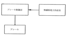
図3に、本発明によるエレベータの作動ブレーキの制御部の構造を概略的に示す。エレベータの作動ブレーキは、たとえば少なくともエレベータの作動ブレーキと、この作動ブレーキの制御部と、ブレーキおよびその制御部への無瞬断電力供給部とを含んでいてよい。無瞬断電力供給部は、たとえば機器に対する予備電力を得ることによって実現でき、たとえば複数の蓄電装置または同様の構造のものにより構成することができる。エレベータの作動ブレーキの制御に必要な構成機器および構成部品を図3とは異なるようにすることができる。 FIG. 3 schematically shows the structure of the control unit of the elevator operating brake according to the present invention. The elevator operating brake may include, for example, at least an elevator operating brake, a control unit for the operating brake, and an uninterruptible power supply unit for the brake and the control unit. The uninterruptible power supply unit can be realized, for example, by obtaining reserve power for the device, and can be configured by, for example, a plurality of power storage devices or a similar structure. The components and components necessary for controlling the elevator operating brake can be different from those shown in FIG.
図4は、エレベータの作動ブレーキ制御を流れ図として概略的に示した図である。この制御は複数のステップからなり、まず、緊急制動の状況であるか否かを判断する。判断の結果、緊急制動の状況でなければ、ブレーキの動作はブレーキ制御部によって通常どおりに制御される。他方、緊急制動の状況である場合では、エレベータの作動ブレーキは、エレベータかごがどの方向に動いているかを認識する必要がある。エレベータかごが下降中である場合、次のステップではエレベータのブレーキが通常どおりに制御される。他方、エレベータが上昇中であることが確認された場合、制御部は、事前に決められた制動遅れを実施する。この制動遅れは一定にしてもよく、または加速度および/または速度および質量に応じて決めてもよい。 FIG. 4 is a diagram schematically showing the elevator brake control as a flowchart. This control includes a plurality of steps. First, it is determined whether or not an emergency braking situation is present. If the result of the determination is that there is no emergency braking, the brake operation is controlled as usual by the brake control unit. On the other hand, in the case of an emergency braking situation, the elevator operating brake needs to recognize in which direction the elevator car is moving. If the elevator car is descending, the next step is to control the elevator brakes normally. On the other hand, when it is confirmed that the elevator is moving up, the control unit executes a predetermined braking delay. This braking delay may be constant or may be determined according to acceleration and / or speed and mass.
本発明のエレベータの好ましい実施例は、駆動機が被覆されたトラクションシーブを有する機械室付きのエレベータである。巻上機は、1つのトラクションシーブおよび1つの方向転換プーリを有し、このトラクションシーブと方向転換プーリとが互いに正しい角度で事前に取り付けられている。巻上機はその制御機器と共にエレベータの機械室内に設けられ、またこの室内にはエレベータの補正システムが配されている。このエレベータは、釣合重りがなく、懸垂比2:1で駆動する。よってエレベータかご上方のローピングの懸垂比およびエレベータかご下方のローピングの懸垂比は共に2:1であり、さらにエレベータのローピングが、エレベータかごの壁のうちの1つとエレベータシャフトの壁との間の空間を走行する。エレベータは、1つの補正システムを有し、これはロープテンション間の比率T1/T2を約2:1の一定の比率に保つ。エレベータの補正システムは、少なくとも1つの固定手段、好ましくは制動部材および/またはロープ緩み防止手段を含み、巻上ロープの制御不能な緩み、および/または上記補正システムの制御不能な運動を防止する。このロープ緩み防止手段は、好ましくは緩衝器である。方向転換プーリと、その懸垂構造と、方向転換プーリに連結する追加重量との質量により生じる追加の力は補正システムで利用される。この付加力は実質的には第1のロープテンションT1と同じ方向に向かって、ロープテンションT2を増大し、それによって比率T1/T2をより有利にする。 A preferred embodiment of the elevator of the present invention is an elevator with a machine room having a traction sheave covered with a driving machine. The hoisting machine has one traction sheave and one diverting pulley, and the traction sheave and diverting pulley are pre-attached at the correct angle to each other. The hoisting machine is provided in the machine room of the elevator together with the control device, and an elevator correction system is arranged in this room. This elevator has no counterweight and is driven with a suspension ratio of 2: 1. Therefore, the suspension ratio of the roping above the elevator car and the suspension ratio of the roping below the elevator car are both 2: 1, and further the elevator roping is the space between one of the elevator car walls and the wall of the elevator shaft. Drive on. The elevator has one correction system, which keeps the ratio T 1 / T 2 between the rope tensions at a constant ratio of about 2: 1. The elevator correction system includes at least one fixing means, preferably a braking member and / or rope loosening prevention means, to prevent uncontrollable loosening of the hoisting rope and / or uncontrollable movement of the correction system. This rope loosening prevention means is preferably a shock absorber. The additional force generated by the mass of the turning pulley, its suspension structure and the additional weight coupled to the turning pulley is utilized in the correction system. This additional force increases the rope tension T 2 in substantially the same direction as the first rope tension T 1 , thereby making the ratio T 1 / T 2 more advantageous.
当業者には明らかなように、本発明のさまざまな実施例は、以上に説明した実施例に限定されることはなく、上記の特許請求の範囲の範囲内で変更できる。たとえば、エレベータシャフトの上部とエレベータかごとの間、およびその下方の方向転換プーリとエレベータかごとの間に、巻上げロープを通す回数は大きな決定的な問題ではなく、多様なロープの走路を用いていくつかの付加的な利点を達成することができる。通常の適用では、ロープが下方からと同じ回数で上方から走行してエレベータかごへ向かい、上方へ走行する方向転換プーリと下方へ走行する方向転換プーリとの懸垂比が同じになるように行われる。また、巻上げロープを必ずしもかごの下に通す必要がないことも明らかである。以上に説明した実施例によれば、当業者は本発明の実施例を変更することができ、他方、トラクションシーブおよびローププーリを、被覆した金属プーリの代わりに、未被覆金属プーリ、またはこの目的に適した他の材料で作られた未被覆プーリにすることもできる。 As will be apparent to those skilled in the art, the various embodiments of the present invention are not limited to the embodiments described above, but may vary within the scope of the appended claims. For example, the number of passes of the hoisting rope between the upper part of the elevator shaft and the elevator car and between the direction change pulley and the elevator car below it is not a big decisive problem. Several additional benefits can be achieved. In normal application, the rope runs from the top as many times as it goes from below and heads to the elevator car so that the suspension ratio of the direction change pulley that runs upward and the direction change pulley that runs downward is the same. . It is also clear that the hoisting rope does not necessarily have to pass under the car. According to the embodiments described above, one of ordinary skill in the art can modify the embodiments of the present invention, while the traction sheave and rope pulley can be replaced with an uncoated metal pulley, or for this purpose, instead of a coated metal pulley. It can also be an uncoated pulley made of other suitable materials.
さらに、当業者には明らかなように、本発明において用いられるトラクションシーブおよび方向転換プーリは、金属製でもこの目的に適した材料で作られるものでも、方向転換プーリとして機能し、少なくともそれぞれの溝の領域では非金属材料で被覆され、たとえばゴム、プラスチック、ポリウレタン、またはこの目的に適した他の材料から成る被覆材を用いて実行することができる。また、当業者には明らかなように、たとえばエレベータのくさび把持中に生じる補正システムの急速な動きの際に、本発明の付加力がロープ力に慣性項を生じさせ、これが補正システムの運動に抵抗しようとする。方向転換プーリ/複数の方向転換プーリの加速度および補正システムの追加重量が大きいほど、慣性質量の重要性が増し、これが補正システムの運動に抵抗して、補正システムの緩衝器に対する衝撃を減少させる。なぜならば、補正システムの運動が重力に対して生じるからである。また、当業者には明らかなように、エレベータかごおよび機械ユニットを、エレベータシャフトの横断面において、実施例に説明したレイアウトとは異なる方法でレイアウトすることができる。このような異なるレイアウトとしては、たとえば機械がシャフトドアから見てかごの背後に配され、ロープがかごの下を通ってこのかごの底部に対して対角線的であるものがある。ロープをかごの下で対角に、さもなければ、底部の形に対して斜めの方向に通すことは、ロープによるかごの懸垂が、他の種類の懸垂レイアウトにおいても、質量の中心に対して対称に行われるのと同様にされる場合に利点を生む。 Further, as will be apparent to those skilled in the art, the traction sheave and diverting pulley used in the present invention, whether made of metal or made of a material suitable for this purpose, function as a diverting pulley, at least in each groove. This region is coated with a non-metallic material and can be carried out with a coating made of, for example, rubber, plastic, polyurethane or other materials suitable for this purpose. Also, as will be apparent to those skilled in the art, during the rapid movement of the correction system that occurs, for example, during elevator wedge gripping, the additional force of the present invention causes an inertial term in the rope force, which contributes to the movement of the correction system. Try to resist. The greater the acceleration of the turning pulley / multiple turning pulleys and the additional weight of the correction system, the more important the inertial mass is, which resists the movement of the correction system and reduces the impact on the shock absorber of the correction system. This is because the movement of the correction system occurs with respect to gravity. Also, as will be apparent to those skilled in the art, the elevator car and the machine unit can be laid out in a cross section of the elevator shaft in a manner different from that described in the embodiments. An example of such a different layout is that the machine is placed behind the car as viewed from the shaft door and the rope is diagonal to the bottom of the car through the car. Passing the rope diagonally under the cage, or diagonally to the shape of the bottom, means that the rope's cage suspension is relative to the center of mass in other types of suspension layouts. It produces an advantage when done in the same way as done symmetrically.
また、当業者には明らかなように、モータへ動力を供給するのに必要な機器およびエレベータの制御に必要な機器を、機械装置に関連した以外のいずれかの場所、たとえば別個の計器盤に配置することができ、または制御に必要な機器を、別個の装置として実行することができ、これをエレベータシャフトのさまざまな場所に、および/または建物の他の部分に配置することができる。同様に、本発明を適用しているエレベータを以上に説明した実施例とは異なるように装備できることは、当業者には明らかである。さらに、当業者には明らかなように、本発明のエレベータを、たとえば1つ以上のストランドの可撓性ロープ、平ロープ、コグドベルト、台形ベルト、またはこの目的に適用可能な他の種類のベルトなどを巻上げロープとして、ほとんどの種類の可撓性巻上げ手段を用いて実行することができる。また、フィラー型ロープを用いるのではなく、潤滑されたまたは未潤滑のフィラーなしのロープを用いて本発明を実行できることは、当業者には明らかである。さらに、ロープをさまざまな方法で撚ることができることは、当業者には明らかである。 It will also be apparent to those skilled in the art that the equipment needed to power the motor and the equipment needed to control the elevator can be placed elsewhere, such as in a separate instrument panel. The equipment that can be deployed or required for control can be implemented as a separate device, which can be placed at various locations on the elevator shaft and / or in other parts of the building. Similarly, it will be apparent to those skilled in the art that an elevator to which the present invention is applied can be equipped differently from the embodiments described above. Further, as will be apparent to those skilled in the art, the elevator of the present invention can be used, for example, one or more strands of flexible rope, flat rope, cogged belt, trapezoidal belt, or other types of belts applicable for this purpose. Can be implemented using most types of flexible winding means. It will also be apparent to those skilled in the art that the present invention can be practiced using a lubricated or unlubricated filler-free rope rather than using a filler-type rope. Furthermore, it will be apparent to those skilled in the art that the rope can be twisted in various ways.
また、当業者には明らかなように、本発明のエレベータを、トラクションシーブと方向転換プーリ/複数の方向転換プーリとの間にさまざまなローピング装置を用いて、実施例として説明したものよりも接触角αを大きくして実行することができる。たとえば、方向転換プーリ/複数の方向転換プーリ、トラクションシーブおよび巻上げロープを、実施例に説明したローピング装置における以外の方法で配置することができる。また、当業者には明らかなように、本発明のエレベータにおいて、エレベータは釣合重りを設けることもでき、このエレベータにおいて、その釣合重りは、たとえば有利には、かごのものよりも小さい重量であり、別個のローピングで懸垂され、エレベータかごは、一部は巻上げロープによって、および一部は釣合重りおよびそのローピングによって懸垂される。 Also, as will be apparent to those skilled in the art, the elevator of the present invention can be contacted more than what is described in the examples using various roping devices between the traction sheave and the direction change pulley / direction change pulleys. The angle α can be increased and executed. For example, the diverting pulley / plurality of diverting pulleys, traction sheaves and hoisting ropes can be arranged in ways other than in the roping device described in the examples. It will also be apparent to those skilled in the art that in the elevator according to the invention, the elevator can also be provided with a counterweight in which, for example, the counterweight advantageously has a lower weight than that of the car. And suspended by separate ropings, the elevator car is suspended partly by a hoisting rope and partly by a counterweight and its roping.
方向転換プーリとして用いられるローププーリのベアリング抵抗と、ロープおよびロープシーブ間の摩擦、ならびに補正システムにおいて生じる可能性のある損失とにより、ロープテンション間の比は補正システムの公称比からは幾分かの偏差がある。5 %の偏差でも、さほど大きな不利にはならない。なぜならば、いかなる場合においても、エレベータは一定の固有の強さを持つ必要があるからである。 The ratio between the rope tensions is somewhat deviated from the nominal ratio of the compensation system due to the bearing resistance of the rope pulley used as the turning pulley, the friction between the rope and the rope sheave, and the loss that can occur in the compensation system. There is. Even a 5% deviation is not a big disadvantage. This is because, in any case, the elevator needs to have a certain inherent strength.
Claims (4)
Applications Claiming Priority (3)
| Application Number | Priority Date | Filing Date | Title |
|---|---|---|---|
| FI20041044A FI20041044A (en) | 2004-07-30 | 2004-07-30 | Elevator |
| FI20041044 | 2004-07-30 | ||
| PCT/FI2005/000262 WO2006010781A2 (en) | 2004-07-30 | 2005-06-06 | Safety brake for elevator without counterweight |
Related Child Applications (1)
| Application Number | Title | Priority Date | Filing Date |
|---|---|---|---|
| JP2014047465A Division JP5873884B2 (en) | 2004-07-30 | 2014-03-11 | elevator |
Publications (3)
| Publication Number | Publication Date |
|---|---|
| JP2008508158A JP2008508158A (en) | 2008-03-21 |
| JP2008508158A5 JP2008508158A5 (en) | 2008-06-26 |
| JP5524448B2 true JP5524448B2 (en) | 2014-06-18 |
Family
ID=32749251
Family Applications (2)
| Application Number | Title | Priority Date | Filing Date |
|---|---|---|---|
| JP2007523091A Expired - Fee Related JP5524448B2 (en) | 2004-07-30 | 2005-06-06 | elevator |
| JP2014047465A Expired - Fee Related JP5873884B2 (en) | 2004-07-30 | 2014-03-11 | elevator |
Family Applications After (1)
| Application Number | Title | Priority Date | Filing Date |
|---|---|---|---|
| JP2014047465A Expired - Fee Related JP5873884B2 (en) | 2004-07-30 | 2014-03-11 | elevator |
Country Status (20)
| Country | Link |
|---|---|
| US (1) | US7712584B2 (en) |
| EP (1) | EP1771373B1 (en) |
| JP (2) | JP5524448B2 (en) |
| KR (1) | KR101098923B1 (en) |
| CN (1) | CN1993286B (en) |
| AR (1) | AR050182A1 (en) |
| AT (1) | ATE396137T1 (en) |
| AU (1) | AU2005266341B2 (en) |
| BR (1) | BRPI0513993A (en) |
| CA (1) | CA2571442C (en) |
| DE (1) | DE602005007031D1 (en) |
| EA (1) | EA009750B1 (en) |
| ES (1) | ES2303252T3 (en) |
| FI (1) | FI20041044A (en) |
| HK (1) | HK1101160A1 (en) |
| MX (1) | MX2007001085A (en) |
| MY (1) | MY139421A (en) |
| TW (1) | TWI339185B (en) |
| WO (1) | WO2006010781A2 (en) |
| ZA (1) | ZA200700383B (en) |
Cited By (1)
| Publication number | Priority date | Publication date | Assignee | Title |
|---|---|---|---|---|
| JP2014101230A (en) * | 2004-07-30 | 2014-06-05 | Kone Corp | Elevator |
Families Citing this family (13)
| Publication number | Priority date | Publication date | Assignee | Title |
|---|---|---|---|---|
| FI119768B (en) | 2006-01-16 | 2009-03-13 | Kone Corp | Elevator and lift brake |
| FI118729B (en) | 2006-04-04 | 2008-02-29 | Kone Corp | Arrangement to stop a lift basket in an emergency and lift |
| FI119767B (en) * | 2006-08-14 | 2009-03-13 | Kone Corp | Elevator system and method for ensuring safety in the elevator system |
| FI120302B (en) * | 2008-04-17 | 2009-09-15 | Kone Corp | Arrangement and procedure in a lift without counterweight |
| US20120006630A1 (en) * | 2009-06-12 | 2012-01-12 | Min Allan Wang | Elevator governor device |
| CN102408045A (en) * | 2010-09-26 | 2012-04-11 | 安徽中菱电梯有限公司 | Safety mechanism for non-counter-weight traction passenger lift |
| DE202011001845U1 (en) | 2011-01-24 | 2012-04-30 | Liebherr-Components Biberach Gmbh | Cable drum and pulley for fiber rope drives |
| CN104870357B (en) * | 2012-11-16 | 2019-01-15 | 通力股份公司 | Elevator and the wiring for tensing elevator or the pre-tensioned method around band |
| CN105398919A (en) * | 2014-09-11 | 2016-03-16 | 上海现代电梯制造有限公司 | Traction structure of lower-driven type counterweight-free elevator |
| EP3103751A1 (en) * | 2015-06-10 | 2016-12-14 | Otis Elevator Company | Drive assisted emergency stop |
| CN106744159B (en) * | 2017-01-20 | 2024-04-09 | 西继迅达电梯有限公司 | Ultra-high-speed elevator and compensating rope tensioning device thereof |
| CN107618963B (en) * | 2017-10-31 | 2023-02-28 | 杭州奥立达电梯有限公司 | Large-load goods elevator suspension system with traction ratio of 6 to 1 |
| US11040848B2 (en) | 2018-03-27 | 2021-06-22 | Otis Elevator Company | Elevator machine brake delay control |
Family Cites Families (28)
| Publication number | Priority date | Publication date | Assignee | Title |
|---|---|---|---|---|
| US998016A (en) | 1911-03-22 | 1911-07-18 | Sangamo Electric Co | Recording mechanism for meters. |
| US1980230A (en) * | 1931-10-19 | 1934-11-13 | See Elevator Company Inc Ab | Elevator |
| US2403125A (en) * | 1944-10-04 | 1946-07-02 | Westinghouse Electric Corp | Control system |
| DE1251926B (en) * | 1965-04-28 | 1967-10-12 | Haushahn Fa C | Elevator for high, lateral bends underlying towers |
| US3613835A (en) * | 1969-10-02 | 1971-10-19 | Falconi & C Spa G | Programmed braking for elevators and the like |
| GB1442584A (en) * | 1974-04-05 | 1976-07-14 | Johns & Waygood Ltd | Drive systems for lifts and hoists |
| FR2563299B1 (en) * | 1984-04-24 | 1989-08-11 | Klein Georges | IMPROVEMENTS TO ANGULAR ANTI-RETURN DEVICES |
| JPS6335772U (en) * | 1986-08-25 | 1988-03-08 | ||
| FI20021959A (en) | 2002-11-04 | 2004-05-05 | Kone Corp | Elevator |
| US4923055A (en) * | 1989-01-24 | 1990-05-08 | Delaware Capital Formation, Inc. | Safety mechanism for preventing unintended motion in traction elevators |
| JPH0829904B2 (en) | 1990-03-15 | 1996-03-27 | 三菱電機株式会社 | Elevator installation method |
| US5007505A (en) * | 1990-03-19 | 1991-04-16 | Northern Elevator Limited | Elevator traction sheave brake |
| JPH04201964A (en) | 1990-11-30 | 1992-07-22 | Mitsubishi Electric Corp | Braking device for low press elevator |
| JPH04338089A (en) * | 1991-05-13 | 1992-11-25 | Hitachi Ltd | Braking device |
| DE9201374U1 (en) * | 1992-02-05 | 1992-04-02 | C. Haushahn Gmbh & Co, 7000 Stuttgart, De | |
| DE69428394T2 (en) | 1993-05-21 | 2002-07-04 | Koninkl Philips Electronics Nv | Charge coupled imaging device |
| FI94123C (en) | 1993-06-28 | 1995-07-25 | Kone Oy | Pinion Elevator |
| FI93632C (en) | 1993-06-28 | 1995-05-10 | Kone Oy | Sub-lift type drive lift |
| JPH08198542A (en) | 1995-01-30 | 1996-08-06 | Otis Elevator Co | Elevator with braking force adjusting device |
| DE19632850C2 (en) * | 1996-08-14 | 1998-09-10 | Regina Koester | Traction sheave elevator without counterweight |
| US5788018A (en) * | 1997-02-07 | 1998-08-04 | Otis Elevator Company | Traction elevators with adjustable traction sheave loading, with or without counterweights |
| US6173813B1 (en) * | 1998-12-23 | 2001-01-16 | Otis Elevator Company | Electronic control for an elevator braking system |
| EP1305249B1 (en) * | 2000-07-29 | 2004-10-27 | Alpha Getriebebau GmbH | Elevator car with a driving pulley driving machine integrated therein |
| TW513374B (en) * | 2000-12-08 | 2002-12-11 | Inventio Ag | Safety brake with retardation-dependent braking force |
| JP2004067365A (en) * | 2002-08-09 | 2004-03-04 | Otis Elevator Co | Elevator device |
| FI114458B (en) | 2002-12-02 | 2004-10-29 | Kone Corp | Method and apparatus for installing a lift during the construction phase of a building |
| FI20041044A (en) * | 2004-07-30 | 2006-02-08 | Kone Corp | Elevator |
| JPWO2006038284A1 (en) * | 2004-10-05 | 2008-05-15 | 三菱電機株式会社 | Elevator emergency brake system |
-
2004
- 2004-07-30 FI FI20041044A patent/FI20041044A/en not_active Application Discontinuation
-
2005
- 2005-06-06 KR KR1020077000555A patent/KR101098923B1/en not_active IP Right Cessation
- 2005-06-06 CA CA2571442A patent/CA2571442C/en not_active Expired - Fee Related
- 2005-06-06 MX MX2007001085A patent/MX2007001085A/en active IP Right Grant
- 2005-06-06 EP EP05748873A patent/EP1771373B1/en active Active
- 2005-06-06 CN CN200580025902XA patent/CN1993286B/en not_active Expired - Fee Related
- 2005-06-06 EA EA200700022A patent/EA009750B1/en not_active IP Right Cessation
- 2005-06-06 AU AU2005266341A patent/AU2005266341B2/en not_active Ceased
- 2005-06-06 DE DE602005007031T patent/DE602005007031D1/en active Active
- 2005-06-06 ES ES05748873T patent/ES2303252T3/en active Active
- 2005-06-06 BR BRPI0513993-7A patent/BRPI0513993A/en not_active IP Right Cessation
- 2005-06-06 JP JP2007523091A patent/JP5524448B2/en not_active Expired - Fee Related
- 2005-06-06 AT AT05748873T patent/ATE396137T1/en active
- 2005-06-06 WO PCT/FI2005/000262 patent/WO2006010781A2/en active IP Right Grant
- 2005-07-08 TW TW094123151A patent/TWI339185B/en not_active IP Right Cessation
- 2005-07-14 MY MYPI20053235A patent/MY139421A/en unknown
- 2005-07-26 AR ARP050103092A patent/AR050182A1/en active IP Right Grant
-
2007
- 2007-01-05 US US11/649,807 patent/US7712584B2/en not_active Expired - Fee Related
- 2007-01-12 ZA ZA2007/00383A patent/ZA200700383B/en unknown
- 2007-08-23 HK HK07109166.2A patent/HK1101160A1/en not_active IP Right Cessation
-
2014
- 2014-03-11 JP JP2014047465A patent/JP5873884B2/en not_active Expired - Fee Related
Cited By (1)
| Publication number | Priority date | Publication date | Assignee | Title |
|---|---|---|---|---|
| JP2014101230A (en) * | 2004-07-30 | 2014-06-05 | Kone Corp | Elevator |
Also Published As
| Publication number | Publication date |
|---|---|
| MX2007001085A (en) | 2007-03-21 |
| BRPI0513993A (en) | 2008-05-20 |
| EA009750B1 (en) | 2008-04-28 |
| CN1993286B (en) | 2012-06-06 |
| CA2571442C (en) | 2012-07-03 |
| AU2005266341B2 (en) | 2009-09-03 |
| EA200700022A1 (en) | 2007-08-31 |
| FI20041044A0 (en) | 2004-07-30 |
| MY139421A (en) | 2009-09-30 |
| AU2005266341A1 (en) | 2006-02-02 |
| JP5873884B2 (en) | 2016-03-01 |
| WO2006010781A3 (en) | 2006-06-01 |
| TW200607743A (en) | 2006-03-01 |
| WO2006010781A2 (en) | 2006-02-02 |
| CA2571442A1 (en) | 2006-02-02 |
| DE602005007031D1 (en) | 2008-07-03 |
| TWI339185B (en) | 2011-03-21 |
| AR050182A1 (en) | 2006-10-04 |
| EP1771373B1 (en) | 2008-05-21 |
| KR101098923B1 (en) | 2011-12-27 |
| CN1993286A (en) | 2007-07-04 |
| ZA200700383B (en) | 2008-08-27 |
| US20070227833A1 (en) | 2007-10-04 |
| US7712584B2 (en) | 2010-05-11 |
| JP2008508158A (en) | 2008-03-21 |
| KR20070049137A (en) | 2007-05-10 |
| JP2014101230A (en) | 2014-06-05 |
| FI20041044A (en) | 2006-02-08 |
| EP1771373A2 (en) | 2007-04-11 |
| HK1101160A1 (en) | 2007-10-12 |
| ES2303252T3 (en) | 2008-08-01 |
| ATE396137T1 (en) | 2008-06-15 |
Similar Documents
| Publication | Publication Date | Title |
|---|---|---|
| JP5524448B2 (en) | elevator | |
| JP5122953B2 (en) | elevator | |
| JP5095401B2 (en) | Elevator installation method and elevator | |
| US8235179B2 (en) | Elevator without a counterweight | |
| KR101107065B1 (en) | Elevator | |
| US20050284705A1 (en) | Elevator | |
| US20060196730A1 (en) | Elevator and arrangement | |
| JP4847336B2 (en) | elevator |
Legal Events
| Date | Code | Title | Description |
|---|---|---|---|
| A521 | Request for written amendment filed |
Free format text: JAPANESE INTERMEDIATE CODE: A523 Effective date: 20080508 |
|
| A621 | Written request for application examination |
Free format text: JAPANESE INTERMEDIATE CODE: A621 Effective date: 20080508 |
|
| A131 | Notification of reasons for refusal |
Free format text: JAPANESE INTERMEDIATE CODE: A131 Effective date: 20110830 |
|
| A601 | Written request for extension of time |
Free format text: JAPANESE INTERMEDIATE CODE: A601 Effective date: 20111129 |
|
| A602 | Written permission of extension of time |
Free format text: JAPANESE INTERMEDIATE CODE: A602 Effective date: 20111206 |
|
| A601 | Written request for extension of time |
Free format text: JAPANESE INTERMEDIATE CODE: A601 Effective date: 20111227 |
|
| A602 | Written permission of extension of time |
Free format text: JAPANESE INTERMEDIATE CODE: A602 Effective date: 20120110 |
|
| A521 | Request for written amendment filed |
Free format text: JAPANESE INTERMEDIATE CODE: A523 Effective date: 20120127 |
|
| A02 | Decision of refusal |
Free format text: JAPANESE INTERMEDIATE CODE: A02 Effective date: 20120807 |
|
| A521 | Request for written amendment filed |
Free format text: JAPANESE INTERMEDIATE CODE: A523 Effective date: 20121206 |
|
| A911 | Transfer to examiner for re-examination before appeal (zenchi) |
Free format text: JAPANESE INTERMEDIATE CODE: A911 Effective date: 20130118 |
|
| A912 | Re-examination (zenchi) completed and case transferred to appeal board |
Free format text: JAPANESE INTERMEDIATE CODE: A912 Effective date: 20130315 |
|
| A601 | Written request for extension of time |
Free format text: JAPANESE INTERMEDIATE CODE: A601 Effective date: 20130712 |
|
| A602 | Written permission of extension of time |
Free format text: JAPANESE INTERMEDIATE CODE: A602 Effective date: 20130718 |
|
| A601 | Written request for extension of time |
Free format text: JAPANESE INTERMEDIATE CODE: A601 Effective date: 20130815 |
|
| A602 | Written permission of extension of time |
Free format text: JAPANESE INTERMEDIATE CODE: A602 Effective date: 20130820 |
|
| A601 | Written request for extension of time |
Free format text: JAPANESE INTERMEDIATE CODE: A601 Effective date: 20130913 |
|
| A602 | Written permission of extension of time |
Free format text: JAPANESE INTERMEDIATE CODE: A602 Effective date: 20130926 |
|
| A601 | Written request for extension of time |
Free format text: JAPANESE INTERMEDIATE CODE: A601 Effective date: 20140210 |
|
| A602 | Written permission of extension of time |
Free format text: JAPANESE INTERMEDIATE CODE: A602 Effective date: 20140214 |
|
| A521 | Request for written amendment filed |
Free format text: JAPANESE INTERMEDIATE CODE: A523 Effective date: 20140311 |
|
| A61 | First payment of annual fees (during grant procedure) |
Free format text: JAPANESE INTERMEDIATE CODE: A61 Effective date: 20140410 |
|
| R150 | Certificate of patent or registration of utility model |
Ref document number: 5524448 Country of ref document: JP Free format text: JAPANESE INTERMEDIATE CODE: R150 |
|
| R250 | Receipt of annual fees |
Free format text: JAPANESE INTERMEDIATE CODE: R250 |
|
| LAPS | Cancellation because of no payment of annual fees |