JP5523739B2 - Vehicle height limiter in multistage parking system - Google Patents
Vehicle height limiter in multistage parking system Download PDFInfo
- Publication number
- JP5523739B2 JP5523739B2 JP2009116986A JP2009116986A JP5523739B2 JP 5523739 B2 JP5523739 B2 JP 5523739B2 JP 2009116986 A JP2009116986 A JP 2009116986A JP 2009116986 A JP2009116986 A JP 2009116986A JP 5523739 B2 JP5523739 B2 JP 5523739B2
- Authority
- JP
- Japan
- Prior art keywords
- vehicle
- height
- pallet
- metal plate
- column
- Prior art date
- Legal status (The legal status is an assumption and is not a legal conclusion. Google has not performed a legal analysis and makes no representation as to the accuracy of the status listed.)
- Expired - Fee Related
Links
Images


Description
本発明は、低車高車両用の駐車スペースに高車高車両を誤入庫することを防止するための多段式駐車装置における車両高さ制限装置に関するものである。 The present invention relates to a vehicle height limiting device in a multistage parking apparatus for preventing a high-height vehicle from being erroneously stored in a parking space for a low-height vehicle.
多段式駐車装置は、入庫又は出庫する車両を搭載したパレットを水平方向や上下方向に順次移動させることによって、目的の駐車スペースに入庫させたり、駐車スペースから出庫させることができるようにしてあり、駐車装置を建設する平面的スペースをとらずに多数車両の駐車を効率よく行うようにするものとして、近年様々なタイプのものが開発されてきている。 The multi-stage parking device is designed to move in and out of the target parking space by sequentially moving the pallet on which the vehicle to be loaded or unloaded is moved horizontally or vertically. In recent years, various types have been developed to efficiently park a large number of vehicles without taking up a planar space for constructing a parking device.
多段式駐車装置の一例としては、図5に示す如く、低車高車両3(セダン普通車や低車高の軽自動車などの車高が大体1550mm未満の車両)と高車高車両4(ハイルーフ車、ミドルルーフ車などの車高が大体1550mm以上の車両)とを混在して駐車を可能としたミックス型のものがあり、一般的に、地下部分の掘削作業を最小限に抑えて多段式駐車装置の建設費を減らさせるよう地下駐車空間5は低車高車両3の駐車専用とし、一方、地上駐車部分6は低車高車両3と高車高車両4のいずれも駐車可能なものとしてある。又、車両乗入部1は、低車高車両3と高車高車両4のいずれも乗り入れられ且つ多段式駐車装置の利用者7の通行や、車両3又は4への乗降が快適にできるように広い空間が取られている。
As an example of the multistage parking apparatus, as shown in FIG. 5, a low vehicle height vehicle 3 (a vehicle having a vehicle height of less than 1550 mm such as a sedan ordinary vehicle or a low vehicle light vehicle) and a high vehicle height vehicle 4 (high roof). Vehicles such as cars and middle-roof vehicles with a vehicle height of approximately 1550 mm or more are available in a mixed type that generally allows for parking and is generally multistage with minimal excavation work in the underground In order to reduce the construction cost of the parking device, the
又、多段式駐車装置の他の例としては、図示してないが、駐車できる車両を低車高車両専用としたものがあり、車両乗入部は、図5に示した多段式駐車装置と同様に、多段式駐車装置の利用者の通行や、車両の乗降が快適にできるように広い空間が取られている。 In addition, as another example of the multistage parking apparatus, although not shown, there is a vehicle that can be parked exclusively for low-height vehicles, and the vehicle entry part is the same as the multistage parking apparatus shown in FIG. In addition, a large space is provided so that the users of the multistage parking apparatus can easily pass through and get on and off the vehicle.
このため、多段式駐車装置では、上記した低車高車両専用の駐車スペースとしてあるものであっても車両乗入部に高車高車両を乗り入れることができるようになっているのが実情であり、車両乗入部に配置された低車高車両駐車スペース専用のパレット2に高車高車両を利用者が誤って乗り入れてしまうことがある。この場合、利用者が誤りに気付かずに入庫作業を続けて高車高車両を搭載した低車高車両駐車スペース専用パレット2を、地下駐車空間の駐車スペースに入庫させると、たとえば、図5に示す如く、該高車高車両4のルーフ部分を車両乗入部1にはみ出させた状態にしてしまうことになり、その後、該車両乗入部1の空いた空間に高車高車両を駐車可能なスペースに用いる他のパレット8が横行または下降してくると、該パレット8が高車高車両4のはみ出たルーフ部分に接触して該高車高車両4を傷つけてしまうという事故例が多発する懸念があり、又、該高車高車両4にパレット8が引っ掛かって動かなくなる、という事態が起こる場合がある。このような事態に対しては、利用者7から連絡を受けたサービスセンターの所員が事後的に対応することになるが、この間にパレット8を移動させることが出来ないため誤入庫した利用者7の高車高車両4だけでなく他の利用者7の車両3又は4も出庫出来ないという問題がある。又、利用者7の車両の修理費用が発生し利用者7の負担が大きい。このため、現在では、利用者による誤入庫を防いで上記問題点を解消すべく、種々の多段式駐車装置における車両高さ制限装置が提案されてきている。
For this reason, in the multistage parking apparatus, even if it is a parking space dedicated to the above-described low-height vehicle, the actual situation is that a high-height vehicle can enter the vehicle entry part, A user may accidentally enter a high-height vehicle on the
多段式駐車装置における車両高さ制限装置の一例としては、図示していないが、車両乗入部のパレット手前側に立設させてあって車幅又は車高の少なくとも一方が所定寸法以上の車両を検知するよう門型にしてある検知バーと、該検知バーが車両の入庫方向に揺動させられたときに作動する検知スイッチと、上記車両乗入部のパレット手前側及び車両乗入部の最奥部分付近に設けられてあって上記検知スイッチにより作動させられる警報装置とを備えてなり、所定寸法以上の車幅や車高の車両がパレット上に乗り入れようとした場合や、パレット上に乗り入れようとする車両の進入位置がずれて車両がパレットの幅方向にはみ出してしまう場合に、警報装置を作動させることにより利用者に警告を発するようにして、利用者に、駐車しようとしている多段式駐車装置には利用できないサイズの車両であることや、パレットからの車両のはみ出しを是正することを促すようにした多段式駐車装置における車両高さ制限装置が提案されている(たとえば、特許文献1参照)。 As an example of the vehicle height limiting device in the multistage parking device, although not shown, a vehicle that is erected on the vehicle pallet front side of the pallet and has at least one of the vehicle width and the vehicle height of a predetermined dimension or more. A detection bar that is gate-shaped to detect, a detection switch that operates when the detection bar is swung in the direction of entering the vehicle, and the pallet front side of the vehicle entry portion and the innermost portion of the vehicle entry portion It is provided near the alarm device that is activated by the detection switch, and when a vehicle with a vehicle width or height higher than a predetermined size is about to get on the pallet, or on the pallet. When the vehicle entering position shifts and the vehicle protrudes in the width direction of the pallet, the warning device is activated by operating the alarm device, and the user tries to park. A vehicle height limiting device in a multi-stage parking apparatus has been proposed (see, for example, a vehicle that has a size that cannot be used for the multi-stage parking apparatus that is used) and that corrects the protrusion of the vehicle from the pallet. , See Patent Document 1).
又、多段式駐車装置における車両高さ制限装置の他の例としては、図示していないが、ミックス型の多段式駐車装置における車両の入出庫を許容するフェンス体に、各格納庫の幅方向中央部に位置するよう車高規制手段を備え、且つ該車高規制手段の上方位置に車高規制手段駆動装置を備えるようにして、地下駐車空間の低車高車両用パレットが車両乗入部に呼び出されて、上記フェンス体が低車高車両を低車高車両駐車スペース専用パレット上に受け入れられるよう上昇するときに、上記車高規制手段駆動装置により車高規制手段をフェンス体の下端から突出させるようにして、高車高車両が上記フェンス体を通過して誤ってパレット上に乗り入れようとするのを視覚的・物理的に防ぐようにした多段式駐車装置における車両高さ制限装置も提案されている(たとえば、特許文献2参照)。 In addition, as another example of the vehicle height limiting device in the multistage parking device, although not shown in the drawing, a fence body that allows vehicle entry and exit in the mixed type multistage parking device is arranged in the center in the width direction of each hangar. The vehicle height restricting means is provided so as to be located at a portion, and the vehicle height restricting means driving device is provided above the vehicle height restricting means, so that the low-height vehicle pallet in the underground parking space is called to the vehicle entry portion. When the fence body is raised so that the low-height vehicle is received on the low-height vehicle parking space dedicated pallet, the vehicle height-regulating means driving device causes the vehicle height-regulating means to protrude from the lower end of the fence body. Thus, a vehicle height limiting device in a multi-stage parking device that visually and physically prevents a high-height vehicle from accidentally getting on the pallet through the fence body. It has been proposed (e.g., see Patent Document 2).
ところが、上記特許文献1に記載された多段式駐車装置における車両高さ制限装置では、低車高車両専用の多段式駐車装置に適用した場合には、上記したような問題点を解消することはできるが、ミックス型の多段式駐車装置に適用した場合には、門型の検知バーを高車高車両が通過できるようにしなければならない関係から、車両乗入部にあるパレットに、高車高車両を、検知バーを通過して乗り入れることが可能であり、ミックス型の多段式駐車装置には適用できないという問題がある。
However, in the vehicle height limiting device in the multistage parking device described in
又、門型の検知バーを車両乗入部のパレットの手前側に立設させるものであるため、利用者が車両の運転を誤って検知バーに車両を衝突させて、検知バーを損傷させてしまったような場合には、検知バーを車両乗入部に再び取り付ける工事を行わなければならず、この工事が完了するまでの時間、その車両乗入部から車両の入出庫ができないという問題もある。 In addition, since the gate-shaped detection bar is set up on the front side of the pallet at the vehicle entry part, the user accidentally operates the vehicle and collides the vehicle with the detection bar, thereby damaging the detection bar. In such a case, it is necessary to perform a work for reattaching the detection bar to the vehicle entry part, and there is also a problem that the vehicle cannot be loaded or unloaded from the vehicle entry part until this work is completed.
更に、検知バーを門型として車両の車高だけでなく車幅も制限するようにしているため、運転に不慣れな利用者が入庫をしようとするときには、何度も車両の幅方向のずれを修正する必要が生じる場合があり、利用者にとって使い勝手が悪いという問題もある。 In addition, the detection bar is a gate type that limits not only the vehicle height but also the vehicle width, so that when a user unfamiliar with driving tries to enter the warehouse, the vehicle width direction shifts many times. There is a case where it is necessary to correct, and there is a problem that it is not convenient for the user.
一方、上記特許文献2に記載された多段式駐車装置における車両高さ制限装置は、車両乗入部の床面から車高規制手段の下端までの間を車両が通過できるかどうかを利用者自身が視覚のみで判断して、車両の誤入庫を防止するものであるため、たとえば、ミドルルーフ車を運転する利用者が通過することができると勘違いして車両を車高規制手段に衝突させてしまう等のヒューマンエラーを生じる場合がある。この場合、該車両が衝突して損傷した車高規制手段を交換する工事が必要となり、この工事が完了するまで長時間、その車両乗入部から車両の入出庫ができないという問題がある。
On the other hand, the vehicle height restriction device in the multistage parking device described in the above-mentioned
そこで、本発明は、利用者が低車高車両用の駐車スペースに高車高車両を誤入庫することを防止することができるようにすると共に、あらゆるタイプの多段式駐車装置にも適用でき且つ車両が衝突して損傷することがあったとしても容易且つ短時間に復旧を行なうことができる多段式駐車装置における車両高さ制限装置を提供しようとするものである。 Therefore, the present invention can prevent a user from erroneously entering a high-height vehicle into a parking space for a low-height vehicle, and can be applied to any type of multistage parking device. It is an object of the present invention to provide a vehicle height limiting device in a multistage parking apparatus that can be easily and quickly restored even if a vehicle collides and is damaged.
本発明は、上記課題を解決するために、請求項1に対応して、低車高車両駐車スペース専用パレットの幅方向の一側部上面に支柱取付用ブラケットを介して支柱を着脱可能に取り付け、該支柱の上端部に、ベースプレートを上記パレットの中央部側へ向くように取り付けて、該ベースプレートのパレット中央側に面する表面に、自由蝶番の一方の連結用金属板を固定すると共に、自由蝶番の他方の連結用金属板に、上記パレット上に進入する高車高車両の車体を接触させるようにする緩衝部材の一端部を固定し、且つ上記ベースプレートに、先端側にストライカを備えた検出装置を取り付けて、自由蝶番の中央の金属板と上記一方の連結用金属板とが接触して閉じた状態にあるときに上記ストライカが上記中央の金属板に押されて上記検出装置が非作動となり、上記中央の金属板が一方の連結用金属板から離れたとき上記検出装置が作動するようにし、更に、上記高車高車両の車体が、上記緩衝部材に接触して、上記自由蝶番の中央の金属板が一方の連結用金属板から離れたときに上記検出装置から発信される信号により作動する警告用ランプ、警報ブザーを、上記支柱の上記ベースプレート取付位置よりも下方位置に備えてなる構成とする。 In order to solve the above-mentioned problem, the present invention, corresponding to claim 1, detachably attaches a support post to the upper surface of one side part in the width direction of the low-height vehicle parking space dedicated pallet via a support attachment bracket. The base plate is attached to the upper end of the column so as to face the center side of the pallet, and one of the connecting metal plates of the free hinge is fixed to the surface of the base plate facing the pallet center side. One end of a shock-absorbing member is fixed to the other connecting metal plate of the hinge so that the vehicle body of the high-height vehicle entering the pallet comes into contact, and the base plate is provided with a striker on the tip side. When the device is attached and the central metal plate of the free hinge and the one connecting metal plate are in contact and closed, the striker is pushed by the central metal plate and the detection device is Is deactivated, and the detection device is activated when the central metal plate is separated from one of the connecting metal plates, and the vehicle body of the high vehicle is in contact with the buffer member, A warning lamp and an alarm buzzer that are activated by a signal transmitted from the detection device when the central metal plate of the free hinge is separated from one of the connecting metal plates are positioned below the base plate mounting position of the column. It is set as the structure provided.
本発明の多段式駐車装置における車両高さ制限装置によれば、以下の如き優れた効果を
発揮する。
(1)低車高車両駐車スペース専用パレットの幅方向の一側部上面に支柱取付用ブラケットを介して支柱を着脱可能に取り付け、該支柱の上端部に、ベースプレートを上記パレットの中央部側へ向くように取り付けて、該ベースプレートのパレット中央側に面する表面に、自由蝶番の一方の連結用金属板を固定すると共に、自由蝶番の他方の連結用金属板に、上記パレット上に進入する高車高車両の車体を接触させるようにする緩衝部材の一端部を固定し、且つ上記ベースプレートに、先端側にストライカを備えた検出装置を取り付けて、自由蝶番の中央の金属板と上記一方の連結用金属板とが接触して閉じた状態にあるときに上記ストライカが上記中央の金属板に押されて上記検出装置が非作動となり、上記中央の金属板が一方の連結用金属板から離れたとき上記検出装置が作動するようにし、更に、上記高車高車両の車体が、上記緩衝部材に接触して、上記自由蝶番の中央の金属板が一方の連結用金属板から離れたときに上記検出装置から発信される信号により作動する警告用ランプ、警報ブザーを、上記支柱の上記ベースプレート取付位置よりも下方位置に備えてなる構成としてあるので、高車高車両が低車高車両駐車スペース専用のパレット上に乗り入れられようとして、緩衝部材に接触したときに、警告用ランプの点灯や警報ブザーの鳴動により誤入庫になることを利用者に知らせて入庫操作の停止を促すことができ、多段式駐車装置の利用者が低車高車両用の駐車スペースに高車高車両を誤入庫するのを効果的に防止することができる。又、上記パレット上に車両を乗り入れる際に、車両を支柱に衝突させて該支柱を破損してしまった場合でも、支柱は着脱自在に取り付けてあるので、支柱を支柱取付用ブラケットから取り外して交換するだけで車両高さ制限装置を容易且つ短時間に復旧させることができる。更に、パレット上に、本発明の多段式駐車装置における車両高さ制限装置を設ける構成にしてあるので、あらゆるタイプの多段式駐車装置に適用することができる。更に又、警告用ランプの点灯や警報ブザーの鳴動により多段式駐車装置の利用者が低車高車両用の駐車スペースに高車高車両を誤入庫するのを防止するようにしてあるので、サービスセンター所員の要請を減らすことができる。また、緩衝部材が高車高車両に衝突しても回転式のため車両への損傷は無く、利用者の車両修理の負担がなくなる。
(2)又、ベースプレートに検出装置を取り付けて、該検出装置が、自由蝶番の一方の連結用金属板と中央の金属板とが離れるときに作動するようにした構成としたるので、多段式駐車装置の利用者が車両から降りる際に、緩衝部材に接触して緩衝部材を出庫方向に揺動させてしまうようなことがあっても、警告用ランプを点灯させたり、警報ブザーを鳴動させたりすることなく利用者を怪我から守ることができる。
According to the vehicle height restriction device in the multistage parking apparatus of the present invention, the following excellent effects are exhibited.
(1) A column is removably attached to the upper surface of one side in the width direction of the low-height vehicle parking space dedicated pallet via a column mounting bracket, and the base plate is placed on the upper end of the column toward the center of the pallet. The metal plate for connecting one of the free hinges is fixed to the surface of the base plate facing the center side of the pallet, and the other metal plate for connecting the free hinge is placed on the pallet. Fix one end of the buffer member that makes the vehicle body of the high-height vehicle contact, and attach a detection device with a striker on the tip side to the base plate, and connect the metal plate in the center of the free hinge and the one When the striker is pressed against the central metal plate when the metal plate is in contact with the closed metal plate, the detection device is deactivated, and the central metal plate is connected to one of the connecting metal plates. The detection device is activated when the plate is separated from the plate, and the vehicle body of the high-height vehicle is brought into contact with the buffer member so that the central metal plate of the free hinge is separated from one of the coupling metal plates. The warning lamp and the alarm buzzer that are activated by a signal transmitted from the detection device are provided at a position below the base plate mounting position of the support column. Invite the user to stop the warehousing operation by notifying the user that the vehicle will be erroneously lit by lighting the warning lamp or sounding the alarm buzzer when it comes into contact with the buffer member when trying to get on the pallet dedicated to the vehicle parking space It is possible to effectively prevent a user of the multistage parking apparatus from erroneously entering a high-height vehicle into a parking space for a low-height vehicle. In addition, when the vehicle is placed on the pallet, even if the vehicle collides with the support column and the support column is damaged, the support column is detachable, so the support column can be removed from the support bracket and replaced. The vehicle height limiting device can be restored easily and in a short time by simply doing this. Furthermore, since it is set as the structure which provides the vehicle height restriction | limiting apparatus in the multistage parking apparatus of this invention on a pallet, it can apply to all types of multistage parking apparatus. Furthermore, since the warning lamp is turned on and the alarm buzzer sounds, the user of the multistage parking device is prevented from erroneously entering a high-height vehicle into the low-height vehicle parking space. The number of requests from the center staff can be reduced. Further, even if the shock-absorbing member collides with a high-height vehicle, since it is a rotary type, there is no damage to the vehicle, and the user's burden of vehicle repair is eliminated.
(2) Since the detection device is attached to the base plate so that the detection device operates when one of the connecting metal plates of the free hinge is separated from the central metal plate, the multistage type When the parking device user gets out of the vehicle, the warning lamp is turned on or the alarm buzzer is sounded even if the buffer member touches the buffer member and swings the buffer member in the exit direction. You can protect your users from injuries without having to.
以下、本発明を実施するための形態を図面を参照して説明する。 Hereinafter, embodiments for carrying out the present invention will be described with reference to the drawings.
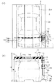
図1乃至図4は本発明の実施の一形態として、図5に示す低車高車両駐車スペース5専用のパレットに適用した場合を示すもので、本発明の車両高さ制限装置は、多段式駐車装置の車両乗入部1に置かれる低車高車両駐車スペース5専用のパレット2の一側部上面2aに立設される支柱取付用ブラケット9と、該支柱取付用ブラケット9に下端部側を嵌入させて着脱可能に取り付けられる支柱10と、該支柱10の上端部所要位置に取り付けられるベースプレート11に自由蝶番12を介して車両3又は4の入出庫方向に揺動自在に取り付けられる緩衝部材14と、該緩衝部材14が車両3又は4の入庫方向へ揺動して自由蝶番12とベースプレート11との間が開くことを検出するため上記ベースプレート11に取り付けられる検出装置16と、該検出装置16からの検出信号を受けて警告用ランプ17を点灯させたり、警報ブザーを作動させるようにする収納ボックス(電池ボックス)18とを備えてなる構成としてある。
1 to 4 show a case where the present invention is applied to a pallet dedicated to a low-height
詳述すると、本発明の車高高さ制限装置は、高車高車両4が駐車しようとして後進しながら上記低車高車両駐車スペース専用のパレット2上に乗り入れようとするときに、該車両4の車体の後部が緩衝部材14に接触して、該緩衝部材14を入庫部の奥側へ回動させることができるようにパレット2の一側部上面2aの手前寄り位置に設置されるようにしてある。
More specifically, the vehicle height-height restricting device of the present invention is arranged such that when the high-
すなわち、パレット2の入庫側の端部から所要距離Lを隔てた位置、たとえば、600mm位隔てた位置で且つ後向きで駐車するときの車両4の助手席側となるパレット一側部上面2aに、円筒状の支柱取付用ブラケット9を上向きに固定する。該ブラケット9のパレット2上面2aへの固定は、ブラケット9のベース部9aの、たとえば、2個所をボルトにて簡易に止めるようにすれば十分であるが、別の固定手段で固定するようにしてもよい。
That is, on the pallet one side
上記パレット2上に直接固定された支柱取付用ブラケット9には、薄肉円筒状とした所要長さの支柱10を、一端側を下端部として上方より挿入し、ブラケット9に設けたボルト孔10aを利用してボルト(図示せず)により着脱可能に取り付けて、鉛直に立てるようにする。上記支柱10の長さ(高さ)は、上端部に取り付ける緩衝部材14の取付位置が、低車高車両3の車高Cよりも高く且つ高車高車両4の車高Aよりも低い位置である1550mmの高さ位置Bが確保できるような寸法となるようにしてある。
The
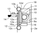
上記支柱10の上端部には、上記緩衝部材14を取り付けるためのベースプレート11をパレット2の中央部側へ向くようにUボルト20にて締結して固定し、該ベースプレート11のパレット2の中央側に面する表面に、2本の平行に配した軸12bと12cに両端部を回動自在に嵌合させた金属板12aと、一方の軸12bに一端部を回動自在に嵌合させた連結用金属板12dと、他方の軸12cに一端部を回動自在に嵌合させた連結用金属板12eとからなり、且つ中央部の金属板12aに対して、2枚の連結用金属板12dと12eが常時接触する方向に閉じているように図示しないスプリングにより付勢されているようにしてある自由蝶番12を位置させ、該自由蝶番12の一方の連結用金属板12dをベースプレート11の表面に溶接等にて一体に接合させるようにする。又、上記自由蝶番12の他方の連結用金属板12eには、パレット2の幅寸法よりやや短い長さ寸法としてある梁部材14aにクッション材を巻いた上にトラテープ14bを巻き付け且つ入庫口側に向く表面に高さ制限のための数値を、たとえば、全高1550mmが目視できるように表示されている高さ表示板14cを取り付けてなる緩衝部材14を、水平状態にして一端側を緩衝部材取付用ブラケット13を介して一体に取り付ける。図1乃至図4では、自由蝶番14の他方の連結用金属板12eに溶接等にて直角方向に取り付けた緩衝部材取付用ブラケット13に、緩衝部材14を片持ち式に自由蝶番12に取り付け支持させるようにしてある。
A
更に、上記ベースプレート11の裏面側には、L字形の検出装置取付用ブラケット15を溶接等にて取り付けて、該ブラケット15に、先端側にストライカ16aを備えた検出装置としてのマイクロリミットスイッチ16を取り付け、自由蝶番12の中央部分の金属板12aが一方の連結用金属板12dに接触して金属板12aと12dが閉じた状態にあるときにはストライカ16aが押されてマイクロリミットスイッチ16が作動せず、金属板12aが緩衝部材14とともに、図3に示す矢印方向に回動して一方の連結用金属板12dから離れたときにマイクロリミットスイッチ16が作動するようにしてある。
Furthermore, an L-shaped detection
更に又、前記支柱10の前記ベースプレート11取付位置よりも下方位置となる支柱10の所要位置には、バッテリーとして乾電池を組み込み、且つ表面にLEDランプを用いた警告用ランプ17と図示しない警報ブザーを備えた収納ボックス(電池ボックス)18を、Uボルト20で締結して取り付けるようにし、上記ベースプレート11に取り付けたマイクロリミットスイッチ16が作動したときに上記収納ボックス18内の電源が励磁させられるようにしてある。
Furthermore, the required position of the
上記において、上記警告用ランプ17及び警報ブザーの電源には乾電池を用いるようにしてあるが、該乾電池の長寿命化を図れるようにするために、警告用ランプ17は、低電圧(約2V)のLEDランプとしてある。更に、該収納ボックス18には、図1(ロ)に示す如く、上記低電圧のLEDランプ(約2V)の電源の乾電池を電源としてある電圧確認用LEDランプ19(約4V)を設けて、図示してないスイッチを押すことにより、該電圧確認用LEDランプ19を点灯できるようにして、上記警告用ランプ17(低電圧のLEDランプ)を点灯させられる電圧が乾電池に残っていることを、テスターを用いることなく多段式駐車装置の管理者が確認できるようにしてある。
In the above description, a dry battery is used as a power source for the warning
なお、図示していないが、マイクロリミットスイッチ16には、カバーをするようにしてスイッチが誤作動することがないようにしてある。
Although not shown, the
本発明の多段式駐車装置における車両高さ制限装置は、上記構成としてあるので、多段式駐車装置における各低車高車両駐車スペース専用パレット2に取り付けておくことにより、車両乗入部1に位置させられるパレット2にはすべて本発明の車両高さ制限装置が装備されたものとなる。
Since the vehicle height limiting device in the multistage parking apparatus of the present invention has the above-described configuration, the vehicle height limiting apparatus is positioned on the
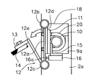
上記の状態において、多段式駐車装置に駐車しようとする車両3又は4のうち、高さ制限をオーバーする高車高車両4が入庫口からパレット2上に進入して乗り入れられると、図1(イ)、図2に示す如くパレット2の幅方向に平行に延び且つ図1(ロ)に示す如く水平状態に支持されている緩衝部材14に、車体の後部の一部が当たる。この際、緩衝部材14は、梁部材14aの表面側がクッションとして機能するようにしてあるので、車体の一部が当たっても該車体の一部が損傷するようなことはない。車体の一部が緩衝部材14に当った状態のままで車両4が更にパレット2上を進入し続けると、緩衝部材14が車両乗入部1の奥側へ押されることにより、緩衝部材14が自由蝶番12に組み込まれているスプリングの弾力に抗して金属板12aと共に軸12bを中心に回動させられることになる。緩衝部材14が自由蝶番12の軸12bを中心に後方へ回動させられると、図3に示す如く、自由蝶番12の中央部の金属板12aが、ベースプレート11に固定されている一方の連結用金属板12dから離れる方向に軸12bを中心に回動させられることになるため、上記自由蝶番12の中央部金属板12aに押されていたマイクロリミットスイッチ16のストライカ16aが作動して、高車高車両4が入庫されようとしていることを検出すると同時に、該マイクロリミットスイッチ16からの信号により収納ボックス18の警告用ランプ17が点灯し、警報ブザーが鳴動し続けるようになる。これにより、万一、利用者である運転者が気付かずにパレット2上への高車高車両4の乗入れを完了したとしても、運転席から車外に出た瞬間に警告用ランプ17の点灯を視覚で確認することができると共に、警報ブザーの鳴動によって聴覚でも確認することができるので、パレット2上に乗り入れた車両4が高さ制限をオーバーしているものであることを認識させることができ、パレット2上から車両4を出し、駐車可能な別の装置への利用を促すことが可能となる。
In the above state, among the
上記において、本発明の車高高さ制限装置は、パレット2上の入庫口側の端部から、たとえば、600mm程度の位置に設置されていることから、入庫しようとする車両がパレット2上に進入を開始した早い段階で、高さ制限をオーバーしている車両については利用者に知らせることができる。
In the above, since the vehicle height limiting device of the present invention is installed at a position of, for example, about 600 mm from the end of the
上記のようにパレット2上に乗り入れた車両4を、パレット2上から出庫させると、緩衝部材14は、自由蝶番12を介して自動復帰させられて、図3の状態から図2の状態に復帰させられる。これにより、ストライカ16aは再び自由蝶番12の金属板12aに接し、マイクロリミットスイッチ16は非作動状態になる。
When the
一方、低車高車両3が多段式駐車装置の車両乗入部1に設けられるパレット2上に乗り入れる場合、低車高車両3の車高は、図1(ロ)にC寸法で示すように、パレット2に進入させることができる最大車高寸法のB寸法よりも低いことになるので、緩衝部材14に接触することになくパレット2上に乗り入れられ、低車高車両3をそのまま多段式駐車装置に入庫させることができる。又、多段式駐車装置の利用者は、パレット2上に低車高車両3を乗り入れた後、該低車高車両3から降りて車両乗入部1から外へ出ようとする際に、体の一部が緩衝部材14に車両乗入部1の奥側から接触しても、自由蝶番12の他方の連結用金属板12eがスプリングの弾力に打ち勝って軸12cを中心に回動して緩衝部材14が図2に示す状態から図4に示す状態になるので、利用者の緩衝部材14への接触を緩和させることができる。この際、自由蝶番12の金属板12aを検出装置としてのマイクロリミットスイッチ16のストライカ16aに当接させた状態を維持でき、これにより、警告用ランプ17が点灯するようなことや警報ブザーが鳴るようなことはない。その後、多段式駐車装置の利用者が、パレット2から降りる等して、緩衝部材14に出庫方向の負荷がかからない状態になると、自由蝶番12に組込まれたスプリングの復元力により、図4に示すような状態から図2に示すような状態に自由蝶番12が自動的に復帰することになる。
On the other hand, when the low
このように、本発明の多段式駐車装置における車両高さ制限装置によれば、高車高車両4が、パレット2上に乗り入れようとして低車高車両3の車高よりも高く且つ高車高車両4の車高よりも低い位置にある緩衝部材14に接触したときにだけ、警告用ランプ17の点灯や警報ブザーによる警報により、このまま入庫操作を続けると誤入庫になることを多段式駐車装置の利用者の視覚又は聴覚の少なくとも一方に訴えることにより確実に知らせられて、多段式駐車装置の利用者の入庫操作の停止を促せられるので、多段式駐車装置の利用者が低車高車両3用の駐車装置に高車高車両4を誤入庫するのを効果的に防止することができる。又、多段式駐車装置の利用者がパレット2上に車両3又は4を乗り入れる際に、パレット2の一側部上面2aに車両3又は4に誤って乗り上げられることにより支柱10に衝突したような場合には、支柱10が破損することにより、車両を傷付けることはなく、又、破損した支柱10は支柱取付用ブラケット9から容易に取り外すことができて交換することができ、本発明の多段式駐車装置における車両高さ制限装置を容易且つ短時間に復旧させることができる。更に、パレット2上に、本発明の多段式駐車装置における車両高さ制限装置を直接設けるようにしてあるので、あらゆるタイプの多段式駐車装置に適用することができ、たとえば、すべての駐車スペースが低車高車両専用の駐車装置の場合には、すべてのパレット2に本発明の車両高さ制限装置を設置するようにすればよい。又、警告用ランプ17の点灯や警報ブザーによる警報により多段式駐車装置の利用者が低車高車両3用の駐車装置に高車高車両4を誤入庫するのを防止することにより、サービスセンター所員の要請を減らすことができる。
As described above, according to the vehicle height limiting device in the multistage parking apparatus of the present invention, the high
又、緩衝部材14は、全長に亘ってトラテープ14bが巻かれた梁部材14aの中央部分に高さ表示板14cを取り付けてなるものとしてあるので、多段式駐車装置の利用者が、車両3又は4をパレット2上に乗り入れようとする前に、多段式駐車装置の利用者が車高を知らない場合には、車両乗入部1の床面からトラテープ14bが巻かれた緩衝部材14までの間を車両3又は4が通過できるかどうかを目視で確認することができ、一方、利用者が車高を知っている場合には、高さ表示板14cに表示された全高の数字により車高制限を確認することができる。
Further, since the
更に、警告用ランプ17及び警報ブザーの電源を、乾電池としてあるので、既設の多段式駐車装置に対して、警告用ランプ17及び警報ブザーの電源の配線工事などを必要とせずに、既設のパレットを本発明の多段式駐車装置における車両高さ制限装置を備えたパレット2に交換するか、既設のパレットに本発明の多段式駐車装置における車両高さ制限装置を取り付ける作業をするだけで、多段式駐車装置の利用者が低車高車両3用の駐車装置に高車高車両4を誤入庫するのを防止することができる。又、警告用ランプ17を低電圧(約2V)のLEDランプとし、該低電圧のLEDランプの電源の乾電池を電源とする電圧確認用LEDランプ(約4V)19と、該電圧確認用LEDランプ19を点灯させるスイッチを設けるようにした構成とすることにより、乾電池に警告用ランプ17を点灯させられる電圧が残っているのかを確認するのにテスターを用いる手間を省いて、上記スイッチを押して電圧確認用LEDランプ19の点灯を確認するようにし、該電圧確認用LEDランプ19が不点灯のときに、乾電池を交換するようにすることができる。このことにより、警告用ランプ17が不点灯状態になることを防止することができる。
Further, since the power source of the warning
なお、上記実施の形態では、支柱10を薄肉厚の円筒形状として、該支柱10の上端部側にベースプレート11を取り付けるようにした場合を例示したが、支柱10を、例えば、薄肉厚の角形鋼管として、該支柱10に直接自由蝶番12を取り付けるようにしてもよいこと、緩衝部材14を、緩衝部材取付用ブラケット15を介して自由蝶番12に取り付けるようにした場合を示したが、直接自由蝶番12に取り付けるようにしてもよいこと、緩衝部材14は、トラテープ14bを巻きつけて目立つようにしたり、高さ表示板14cを取り付けたりしたものとしてあるが、これらに限定されるものではないこと、警告用ランプ17及び警報ブザーの電源を乾電池以外に、他の電源を用いるようにしてもよいこと、その他本発明の要旨を逸脱しない範囲内において種々変更を加え得ることは勿論である。
In the above embodiment, the
2 低車高車両駐車スペース専用パレット
2a 上面
4 高車高車両
9 支柱取付用ブラケット
10 支柱
11 ベースプレート
12 自由蝶番
12a 金属板
12d 一方の連結用金属板
12e 他方の連結用金属板
14 緩衝部材
16 検出装置(マイクロリミットスイッチ)
17 警告用ランプ
2 Pallet dedicated to low-height
17 Warning lamp
Claims (1)
Priority Applications (1)
| Application Number | Priority Date | Filing Date | Title |
|---|---|---|---|
| JP2009116986A JP5523739B2 (en) | 2009-05-13 | 2009-05-13 | Vehicle height limiter in multistage parking system |
Applications Claiming Priority (1)
| Application Number | Priority Date | Filing Date | Title |
|---|---|---|---|
| JP2009116986A JP5523739B2 (en) | 2009-05-13 | 2009-05-13 | Vehicle height limiter in multistage parking system |
Publications (2)
| Publication Number | Publication Date |
|---|---|
| JP2010265653A JP2010265653A (en) | 2010-11-25 |
| JP5523739B2 true JP5523739B2 (en) | 2014-06-18 |
Family
ID=43362847
Family Applications (1)
| Application Number | Title | Priority Date | Filing Date |
|---|---|---|---|
| JP2009116986A Expired - Fee Related JP5523739B2 (en) | 2009-05-13 | 2009-05-13 | Vehicle height limiter in multistage parking system |
Country Status (1)
| Country | Link |
|---|---|
| JP (1) | JP5523739B2 (en) |
Families Citing this family (4)
| Publication number | Priority date | Publication date | Assignee | Title |
|---|---|---|---|---|
| CN106355953A (en) * | 2016-11-11 | 2017-01-25 | 江苏普腾停车设备有限公司 | Vehicle over-high dead zone detection system for parking equipment |
| CN107024904B (en) * | 2017-04-27 | 2023-10-27 | 天津市中环富士智能设备有限公司 | Parking equipment with automatic parking guiding function and guiding method |
| CN108775182B (en) * | 2018-08-31 | 2023-11-10 | 广州建德机电有限公司 | Height limiting indication method and system for mechanical parking space |
| CN115324399B (en) * | 2022-08-01 | 2023-07-25 | 安徽鸿杰威尔停车设备有限公司 | Automatic lifting system of heavy-duty large elevator platform |
Family Cites Families (4)
| Publication number | Priority date | Publication date | Assignee | Title |
|---|---|---|---|---|
| JP3368315B2 (en) * | 1999-12-03 | 2003-01-20 | 東急車輛製造株式会社 | Pallet type parking device |
| JP2003261915A (en) * | 2002-03-12 | 2003-09-19 | Yabuuchi Fumio | Tilting pole |
| JP3831926B2 (en) * | 2004-01-23 | 2006-10-11 | 株式会社相模化学金属 | Pole device for road surface |
| JP4369446B2 (en) * | 2006-06-06 | 2009-11-18 | 新明和エンジニアリング株式会社 | Vertical circulation parking system |
-
2009
- 2009-05-13 JP JP2009116986A patent/JP5523739B2/en not_active Expired - Fee Related
Also Published As
| Publication number | Publication date |
|---|---|
| JP2010265653A (en) | 2010-11-25 |
Similar Documents
| Publication | Publication Date | Title |
|---|---|---|
| JP5523739B2 (en) | Vehicle height limiter in multistage parking system | |
| US7864030B2 (en) | Safety system for trucks | |
| ES2819673T3 (en) | Anti-entrapment device for scissor lifts | |
| US9296335B2 (en) | Standby virtual bumper for parked vehicle protection | |
| US9415986B2 (en) | Safety device | |
| JP6374787B2 (en) | Gate device and gate control system | |
| JP4615056B1 (en) | Traffic direction control device | |
| KR101324815B1 (en) | Emergency-vehicle display device | |
| JP6261274B2 (en) | Safety support device for amusement vehicles | |
| JP4672762B2 (en) | Unauthorized parking prevention device | |
| US20070294946A1 (en) | Garage Door Control System | |
| JP2004251024A (en) | Dangerous object detecting device for construction equipment | |
| JP6709625B2 (en) | Gate device | |
| JP4874563B2 (en) | Outrigger safety device | |
| JP2001220086A (en) | Load cell, and crane overturn alarming device | |
| CN212694591U (en) | Automobile parking positioner | |
| CN112498244A (en) | Pedal apparatus for vehicle and vehicle | |
| KR100866591B1 (en) | System and method for detecting automobile accident | |
| US7196632B2 (en) | Gas safety detector having self-detection function | |
| JP2014177756A (en) | Mechanical parking device | |
| JP7366610B2 (en) | parking device | |
| KR100549220B1 (en) | Safe parking sysrem | |
| US20210380036A1 (en) | Vehicle Backseat Child Detection System | |
| JPH0639002Y2 (en) | Car stop device | |
| KR200434290Y1 (en) | A Multi-guidance post |
Legal Events
| Date | Code | Title | Description |
|---|---|---|---|
| A621 | Written request for application examination |
Free format text: JAPANESE INTERMEDIATE CODE: A621 Effective date: 20111205 |
|
| A977 | Report on retrieval |
Free format text: JAPANESE INTERMEDIATE CODE: A971007 Effective date: 20130315 |
|
| A131 | Notification of reasons for refusal |
Free format text: JAPANESE INTERMEDIATE CODE: A131 Effective date: 20130409 |
|
| A521 | Written amendment |
Free format text: JAPANESE INTERMEDIATE CODE: A523 Effective date: 20130514 |
|
| A131 | Notification of reasons for refusal |
Free format text: JAPANESE INTERMEDIATE CODE: A131 Effective date: 20131001 |
|
| A521 | Written amendment |
Free format text: JAPANESE INTERMEDIATE CODE: A523 Effective date: 20131031 |
|
| TRDD | Decision of grant or rejection written | ||
| A01 | Written decision to grant a patent or to grant a registration (utility model) |
Free format text: JAPANESE INTERMEDIATE CODE: A01 Effective date: 20140401 |
|
| A61 | First payment of annual fees (during grant procedure) |
Free format text: JAPANESE INTERMEDIATE CODE: A61 Effective date: 20140409 |
|
| R150 | Certificate of patent or registration of utility model |
Ref document number: 5523739 Country of ref document: JP Free format text: JAPANESE INTERMEDIATE CODE: R150 |
|
| LAPS | Cancellation because of no payment of annual fees |