JP5523616B2 - Engine undercover for vehicles - Google Patents
Engine undercover for vehicles Download PDFInfo
- Publication number
- JP5523616B2 JP5523616B2 JP2013130206A JP2013130206A JP5523616B2 JP 5523616 B2 JP5523616 B2 JP 5523616B2 JP 2013130206 A JP2013130206 A JP 2013130206A JP 2013130206 A JP2013130206 A JP 2013130206A JP 5523616 B2 JP5523616 B2 JP 5523616B2
- Authority
- JP
- Japan
- Prior art keywords
- engine
- radiator
- protrusion
- hollow
- sound absorbing
- Prior art date
- Legal status (The legal status is an assumption and is not a legal conclusion. Google has not performed a legal analysis and makes no representation as to the accuracy of the status listed.)
- Active
Links
- 230000002265 prevention Effects 0.000 description 11
- 238000010521 absorption reaction Methods 0.000 description 9
- 238000000071 blow moulding Methods 0.000 description 4
- 230000001771 impaired effect Effects 0.000 description 2
- 230000003139 buffering effect Effects 0.000 description 1
- 238000002485 combustion reaction Methods 0.000 description 1
- 230000000694 effects Effects 0.000 description 1
- 238000003475 lamination Methods 0.000 description 1
Images


Landscapes
- Vehicle Interior And Exterior Ornaments, Soundproofing, And Insulation (AREA)
- Cooling, Air Intake And Gas Exhaust, And Fuel Tank Arrangements In Propulsion Units (AREA)
- Body Structure For Vehicles (AREA)
Description
本発明は、中空の吸音室を有する車両用エンジンアンダーカバーに関する。 The present invention relates to a vehicular engine undercover having a hollow sound absorbing chamber.
従来、図7に示すように、車両のエンジン81下方からラジエーター83の下方に亘って、車両のエンジンによる騒音を低減するために板状のエンジンアンダーカバー70が設けられている。符号88はラジエーター前方のバンパーである。しかし、前記エンジンアンダーカバー70にあっては、ラジエーター83を通った空気が、エンジンルーム80内で温められてラジエーターの下端83aとエンジンアンダーカバー70間の隙間を通ってラジエーター83の前方側、すなわちバンパー88側へ回り込み、さらに吸気ダクト(図示せず)を通ってエンジン81に吸い込まれるため、エンジンの燃焼効率が低下する問題がある。
Conventionally, as shown in FIG. 7, a plate-like engine under
また、図7においてエンジンアンダーカバー70の上面に、ラジエーター83の前方又は後方に近接し、ラジエーターの底面の高さより高い突出部75を形成して、エンジン81側からの熱風がラジエーター83の下方を通ってバンパー88側へ回り込むことを防ぐようにしたエンジンアンダーカバーが提案されている(特許文献1)。しかし、前記突出部75を設けたエンジンアンダーカバーにあっては、車両が縁石に乗り上げる等の際に、硬いエンジンアンダーカバーの上面にラジエーター83の下端が衝突してラジエーター83を損傷するおそれがある。
Further, in FIG. 7, a
また、吸音性を高めるため、図8及び図9に示すように、上面に隆起した中空の吸音室91を複数形成したプラスチックのブロー成形体からなるエンジンアンダーカバー90が提案されている(例えば特許文献2)。なお、図8及び図9における符号95は、車両への取り付け部である。しかし、前記吸音室91を有するエンジンアンダーカバー90にあっては、先に示したラジエーター下端とエンジンアンダーカバー間の隙間を通ってバンパー側へエンジンの熱風が回り込む問題があった。さらに、ブロー成形では、一般的に凸状部分を形成した場合、天面(上面)及び側壁が薄くなるため、エンジンアンダーカバー90の生産ライン等で図10に示すように、エンジンアンダーカバー90が積み重ねられた際に、上側のエンジンアンダーカバー90Aの重みによって、下側のエンジンアンダーカバー90は、吸音室91の一部が押し潰されて、吸音室91による吸音効果が低下する問題がある。
In order to improve sound absorption, an engine under
本発明は前記の点に鑑みなされたものであって、ラジエーターの下端をエンジンアンダーカバーが押圧してもラジエーターの損傷を抑えることができ、さらには、エンジンアンダーカバーを積み重ねた際に、吸音室の潰れを防止することができる車両用エンジンアンダーカバーの提供を目的とする。 The present invention has been made in view of the above points, and even when the lower end of the radiator is pressed by the engine under cover, damage to the radiator can be suppressed. Further, when the engine under covers are stacked, a sound absorbing chamber is provided. An object of the present invention is to provide a vehicular engine undercover that can prevent crushing.
請求項1の発明は、車両のエンジン下方と該エンジン前方のラジエーター下方とに亘って配設され、上面には隆起した中空の吸音室が複数形成されたブロー成形体からなる車両用エンジンアンダーカバーにおいて、前記エンジンアンダーカバーの上面には、ラジエーターの下方位置に前記ラジエーターの下端へ向けて前記吸音室より高く突出したラジエーター位置中空突部が形成されていると共に、前記ラジエーター位置中空突部よりもエンジン側に積み重ね支持用中空突部が上方へ向けて突出形成され、前記積み重ね支持用中空突部は、該積み重ね支持用中空突部と前記ラジエーター位置中空突部間に形成されている前記吸音室よりも高さが高くされていることを特徴とする。 According to a first aspect of the present invention, there is provided an engine undercover for a vehicle comprising a blow-molded body which is disposed over a lower part of an engine of a vehicle and a lower part of a radiator in front of the engine, and a plurality of raised hollow sound absorbing chambers are formed on an upper surface. In the upper surface of the engine under cover, a radiator position hollow protrusion projecting higher than the sound absorption chamber toward the lower end of the radiator is formed at a position below the radiator, and more than the radiator position hollow protrusion. A stacking support hollow projection is formed to project upward on the engine side, and the stacking support hollow projection is formed between the stacking support hollow projection and the radiator position hollow projection. The height is made higher than that.
請求項2の発明は、請求項1において、前記積み重ね支持用中空突部は、前記ラジエーター位置中空突部よりもエンジン側に位置するどの吸音室よりも面積が大に形成されていることを特徴とする。なお、前記「面積」は、前記積み重ね支持用中空突部については該積み重ね支持用中空突部の上面(天井部)の面積をいい、一方、前記吸音室については該吸音室の上面(天井部)の面積をいう。 According to a second aspect of the present invention, in the first aspect, the stacking support hollow protrusion is formed to have a larger area than any of the sound absorbing chambers located on the engine side of the radiator position hollow protrusion. And The “area” means the area of the upper surface (ceiling portion) of the stacking support hollow projection for the stacking support hollow projection, while the upper surface (ceiling portion) of the sound absorption chamber is used for the sound absorption chamber. ).
請求項1の発明によれば、ラジエーター位置中空突部によってラジエーター下端が押圧されることがあっても、ラジエーター位置中空突部が中空からなるため、ラジエーター位置中空突部の変形が比較的容易であって緩衝性を有することから、ラジエーター下端の損傷を防ぐことができる。さらに、本発明のエンジンアンダーカバーにあっては積み重ねられた際に、積み重ね支持用中空突部の存在によって、上方に位置する他のエンジンアンダーカバーの下面に吸音室の上端が接触しないため、吸音室が潰れるおそれがなく、吸音性が損なわれることがない。また、積み重ね支持用中空突部は、吸音性を目的として形成されたものではないため、エンジンアンダーカバーの積み重ねによって積み重ね支持用中空突部の上部が潰れることがあっても、エンジンアンダーカバーの吸音性が損なわれるおそれがない。 According to the first aspect of the present invention, even if the lower end of the radiator is pressed by the radiator position hollow protrusion, the radiator position hollow protrusion is hollow, so that the deformation of the radiator position hollow protrusion is relatively easy. In addition, since it has buffering properties, damage to the lower end of the radiator can be prevented. Furthermore, when the engine undercover of the present invention is stacked, the upper end of the sound absorbing chamber does not contact the lower surface of the other engine undercover located above due to the presence of the stacking support hollow protrusions. There is no possibility that the chamber will be crushed, and the sound absorption is not impaired. In addition, since the stacking support hollow protrusions are not formed for the purpose of absorbing sound, even if the upper part of the stacking support hollow protrusions is crushed by the stacking of the engine undercover, the sound absorption of the engine undercover There is no risk of damage.
請求項2の発明によれば、前記積み重ね支持用中空突部を形成する壁部、天井部の板厚が前記吸音室の板厚より厚くなるため、エンジンアンダーカバーを積み重ねた際に、該積み重ね支持用中空突部がつぶれにくいようになっている。なお、ブロー成形において突部の面積を大にすると、突部の壁面及び天井部の板厚が厚くなることについては、周知の事項である。 According to the second aspect of the present invention, since the thickness of the wall portion and the ceiling portion forming the stacking support hollow protrusion is thicker than the thickness of the sound absorbing chamber, The supporting hollow protrusion is not easily crushed. In addition, when the area of a protrusion is enlarged in blow molding, it is a well-known matter that the wall thickness of a protrusion and the plate | board thickness of a ceiling part will become thick.
図1及び図2に示す第1実施例のエンジンアンダーカバー10は、公知のブロー成形によって成形されたプラスチックのブロー成形体からなり、図7に示したエンジンアンダーカバーと同様に車両のエンジン81下方と該エンジン81前方のラジエーター83下方とに亘って配設される。本実施例のエンジンアンダーカバー10は、中空板状体からなり、前記エンジン81の下方からラジエーター83の下方を経てラジエーター83前方のバンパー裏側に近接する大きさからなる。
The engine undercover 10 of the first embodiment shown in FIGS. 1 and 2 is made of a plastic blow-molded body formed by known blow molding, and is similar to the engine undercover shown in FIG. And below the
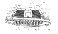
前記エンジンアンダーカバー10の上面11には、上方へ隆起した中空の吸音室15と、ラジエーター位置中空突部19と、積み重ね支持用中空突部23と、取り付け用突部28とが形成されている。
前記吸音室15は、前記エンジンアンダーカバー10の吸音性を高めるためのものであり、前記ラジエーター位置中空突部19の部分を避けて所定位置に複数設けられている。前記吸音室15は、側面及び上面で構成される凸状の中空形状からなり、吸音性を考慮して形状、大きさ及び数が決定されている。
On the
The
前記ラジエーター位置中空突部19は、前記ラジエーター83の下方位置に前記ラジエーター83の下端83aへ向けて上方へ突出すると共に、車両の幅方向と対応するアンダーカバー10の幅方向Wに沿って突堤状に形成されている。本実施例では前記ラジエーター位置中空突部19は、前記吸音室15よりも高さが高くされ、上面20が前記ラジエーター83の下端83aに当接または近接する位置に設定されている。前記エンジンアンダーカバー10において、前記ラジエーター位置中空突部19よりも前方がバンパー側13であり、一方、前記ラジエーター位置中空突部19よりも後方がエンジン側14である。また、本実施例では、前記ラジエーター位置中空突部19の前記幅方向Wの両端には、車体への取り付け孔21,21が形成されている。
The radiator position
前記ラジエーター位置中空突部19の上部には前記ラジエーター83に対してエンジン側14の位置に前記ラジエーターの下端83位置及び前記吸音室15よりも上端位置が高い熱風回り込み防止突部27が形成されている。前記熱風回り込み防止突部27における前記ラジエーターの下端83位置からの高さは適宜決定されるが、例えば1〜5cm程度を挙げる。前記熱風回り込み防止突部27は、前記ラジエーター位置中空突部19における両端間の全長に亘って設けるのが好ましいが、部分的に設けても良い。
At the upper part of the radiator position
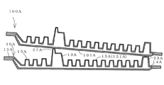
前記積み重ね支持用中空突部23は、前記ラジエーター位置中空突部19よりもエンジン側14の位置に上方へ向けて突出形成されている。前記積み重ね支持用中空突部23は、該積み重ね支持用中空突部23と前記ラジエーター位置中空突部19間に形成されている吸音室151よりも高さが高く形成されると共に、図3に示すように、前記積み重ね支持用中空突部23及び前記ラジエーター位置中空突部19の上に他のエンジンアンダーカバー100が載置された際に、前記吸音室15(積み重ね支持用中空突部23とラジエーター位置中空突部19間の吸音室151を含む)の上端が前記他のエンジンアンダーカバー100の下方に位置して、前記他のエンジンアンダーカバー100の下面101と接触しないように、積み重ね支持用中空突部23の位置及び数が決定されている。特に、前記エンジンアンダーカバー10のエンジン側14において、前記ラジエーター位置中空突部19から最も離れた(すなわち前記エンジン側においてアンダーカバー10の幅方向Wと直交する方向へ前記ラジエーター中空突部19から最も離れた)位置の吸音室152に対して前記幅方向Wの位置、あるいはさらにラジエーター位置中空突部19から離れた位置(すなわち後方位置)に、前記積み重ね支持用中空突部23を設けるのが好ましい。また、前記積み重ね支持用中空突部23は、前記エンジンアンダーカバー10を積み重ねた際に上側のエンジンアンダーカバーを安定させるため、2箇所以上設けるのが好ましい。
The stacking support
また、前記積み重ね支持用中空突部23は、前記ラジエーター位置中空突部19よりもエンジン側に位置するどの吸音室151よりも面積が大きくなっている。そのため、前記積み重ね支持用中空突部23を形成する壁部、天井部の板厚が前記吸音室151の板厚より厚くなっていて、エンジンアンダーカバーを積み重ねた際に、該積み重ね支持用中空突部23がつぶれにくいようになっている。
The stacking support
前記取り付け用突部28は、前記ラジエーター位置中空突部19の車体への取り付け孔21,21と共にエンジンアンダーカバー10を車両へ取り付ける際に利用されるものである。前記取り付け用突部28は上面29を有する筒状からなり、前記上面29に取り付け孔30が形成されている。
The
第1実施例のエンジンアンダーカバー10は、前記ラジエーター位置中空突部19の上部におけるエンジン側14の位置に前記熱風回り込み防止突部27を設けているが、前記熱風回り込み防止突部27は、エンジン側14とは反対のバンパー側13に設けてもよい。
The
図4及び図5に、熱風回り込み防止突部27Aがラジエーター位置中空突部19Aの上部におけるバンパー側13Aに設けられた第2実施例のエンジンアンダーカバー10Aを示す。第2実施例のエンジンアンダーカバー10Aにおいて、熱風回り込み防止突部27Aの位置以外の構成は、前記第1実施例のエンジンアンダーカバー10と同様である。図6には第2実施例のエンジンアンダーカバー10Aを積み重ねた状態を示す。図4乃至図6において、符号11Aはエンジンアンダーカバー10Aの上面、14Aはエンジン側、15Aは吸音室、20Aはラジエーター位置中空突部19Aの上面、21Aはラジエーター位置中空突部19Aに形成された取り付け孔、23Aは積み重ね支持用中空突部、28Aは取り付け用突部である。また、符号100Aは、前記積み重ね支持用中空突部23A及び前記熱風回り込み防止突部27A上に載置された他のエンジンアンダーカバー、101Aは前記他のエンジンアンダーカバー100Aの下面、151Aは積み重ね支持用中空突部23Aとラジエーター位置中空突部19A間に形成された吸音室を示す。
4 and 5 show the engine undercover 10A of the second embodiment in which the hot air sneaking prevention protrusion 27A is provided on the bumper side 13A in the upper part of the radiator position hollow protrusion 19A. In the engine under
前記エンジンアンダーカバー10,10Aは、図2及び図5のように、前記ラジエーター83の下端83aに前記ラジエーター位置中空突部19,19Aの上面を当接または近接させた状態で前記エンジン側14,14Aをエンジン81の下方に位置させ、かつ前記ラジエーター83の下端83aよりも前記熱風回り込み防止突部27,27Aの上端が高い位置となるようにして、エンジン81及びラジエーター83の下方に取り付けられる。
2 and 5, the
車両に取り付けられた前記エンジンアンダーカバー10,10Aは、前記ラジエーター位置中空突部19,19Aの上部に形成された熱風回り込み防止突部27,27Aによって、エンジン81側の熱風がラジエーター83の下端83aとエンジンアンダーカバー10,10A間を通ってエンジン81とは反対のバンパー側13,13Aへ廻り込むのを防止することができる。また、前記ラジエーター位置中空突部19,19Aの上部によってラジエーター下端83aが押圧されることがあっても、ラジエーター位置中空突部19,19Aが中空からなるため、変形が比較的容易であり、該変形によって衝撃を吸収し、ラジエーター下端83aの損傷を防ぐことができる。
The engine undercovers 10 and 10A attached to the vehicle are configured so that the hot air on the
また、前記エンジンアンダーカバー10,10Aは図3及び図6のように、前記積み重ね支持用中空突部27,27A及び前記熱風回り込み防止突部27,27A上に他の同一形状のエンジンアンダーカバー100,100Aが載置された際に、前記吸音室15,15Aの上端が他のエンジンアンダーカバー100,100Aの下方に位置して他のエンジンアンダーカバーの下面101,101Aと接触しないため、吸音室15A,15Aが潰れるおそれがなく、吸音性が損なわれることがない。
As shown in FIGS. 3 and 6, the
10,10A エンジンアンダーカバー
11.11A エンジンアンダーカバーの上面
13,13A バンパー側
14,14A エンジン側
15,15A 吸音室
19,19A ラジエーター位置中空突部
23,23A 積み重ね支持用中空突部、
27,27A 熱風回り込み防止突部
10, 10A Engine under cover 11.11A Engine under cover
27,27A Hot air sneak prevention protrusion
Claims (2)
前記エンジンアンダーカバーの上面には、ラジエーターの下方位置に前記ラジエーターの下端へ向けて前記吸音室(15)より高く突出したラジエーター位置中空突部(19)が形成されていると共に、前記ラジエーター位置中空突部(19)よりもエンジン側に積み重ね支持用中空突部(23)が上方へ向けて突出形成され、
前記積み重ね支持用中空突部(23)は、該積み重ね支持用中空突部と前記ラジエーター位置中空突部間に形成されている前記吸音室(151)よりも高さが高くされていることを特徴とする車両用エンジンアンダーカバー。 In an engine undercover for a vehicle comprising a blow molded body that is disposed over a lower part of a vehicle engine and a lower part of a radiator in front of the engine, and a plurality of raised hollow sound absorbing chambers are formed on the upper surface.
On the upper surface of the engine under cover, there is formed a radiator position hollow protrusion (19) projecting higher than the sound absorbing chamber (15) toward the lower end of the radiator at a position below the radiator, and the radiator position hollow A stacking support hollow protrusion (23) is formed to protrude upward from the protrusion (19) on the engine side,
The stacking support hollow protrusion (23) is higher in height than the sound absorbing chamber (151) formed between the stack support hollow protrusion and the radiator position hollow protrusion. Engine under cover for vehicles.
Priority Applications (1)
| Application Number | Priority Date | Filing Date | Title |
|---|---|---|---|
| JP2013130206A JP5523616B2 (en) | 2013-06-21 | 2013-06-21 | Engine undercover for vehicles |
Applications Claiming Priority (1)
| Application Number | Priority Date | Filing Date | Title |
|---|---|---|---|
| JP2013130206A JP5523616B2 (en) | 2013-06-21 | 2013-06-21 | Engine undercover for vehicles |
Related Parent Applications (1)
| Application Number | Title | Priority Date | Filing Date |
|---|---|---|---|
| JP2009097616A Division JP5302744B2 (en) | 2009-04-14 | 2009-04-14 | Engine undercover for vehicles |
Publications (2)
| Publication Number | Publication Date |
|---|---|
| JP2013177145A JP2013177145A (en) | 2013-09-09 |
| JP5523616B2 true JP5523616B2 (en) | 2014-06-18 |
Family
ID=49269256
Family Applications (1)
| Application Number | Title | Priority Date | Filing Date |
|---|---|---|---|
| JP2013130206A Active JP5523616B2 (en) | 2013-06-21 | 2013-06-21 | Engine undercover for vehicles |
Country Status (1)
| Country | Link |
|---|---|
| JP (1) | JP5523616B2 (en) |
Families Citing this family (1)
| Publication number | Priority date | Publication date | Assignee | Title |
|---|---|---|---|---|
| KR100723233B1 (en) * | 2006-03-31 | 2007-05-29 | 삼성전기주식회사 | White light emitting device |
Family Cites Families (6)
| Publication number | Priority date | Publication date | Assignee | Title |
|---|---|---|---|---|
| JPS5724904Y2 (en) * | 1976-07-29 | 1982-05-29 | ||
| JPH0327885Y2 (en) * | 1985-11-01 | 1991-06-17 | ||
| JPH08207833A (en) * | 1995-02-07 | 1996-08-13 | Yamakawa Ind Co Ltd | Automobile engine under cover with sound absorbing function |
| JPH10121602A (en) * | 1996-08-30 | 1998-05-12 | Nok Megurasutikku Kk | Sound absorbing material |
| JPH10198385A (en) * | 1996-12-27 | 1998-07-31 | Nok Megurasutikku Kk | Sound absorbing material |
| WO2009037765A1 (en) * | 2007-09-20 | 2009-03-26 | Nagoya Oilchemical Co., Ltd. | Buffering and sound-absorbing member |
-
2013
- 2013-06-21 JP JP2013130206A patent/JP5523616B2/en active Active
Also Published As
| Publication number | Publication date |
|---|---|
| JP2013177145A (en) | 2013-09-09 |
Similar Documents
| Publication | Publication Date | Title |
|---|---|---|
| JP5227063B2 (en) | Intake duct for vehicle | |
| JP6443469B2 (en) | Vehicle front structure | |
| JP2013049348A (en) | Front structure of automobile | |
| JP5474151B2 (en) | Intake duct for vehicle | |
| JP5302744B2 (en) | Engine undercover for vehicles | |
| JPWO2012090750A1 (en) | Body front structure | |
| JP5523616B2 (en) | Engine undercover for vehicles | |
| EP1982860A2 (en) | Air guide structure | |
| JP5872362B2 (en) | Fuel tank | |
| JP2020006726A (en) | duct | |
| JP2008290605A (en) | Structure of rear bumper cover | |
| JP2013010472A (en) | Front lower structure of vehicle | |
| JP2007099182A (en) | Hood structure | |
| JP2010188842A (en) | Pedestrian protection absorber for vehicle and vehicle body front part structure | |
| JP6407599B2 (en) | Engine compartment cover | |
| JP6117677B2 (en) | Cowl top cover | |
| JP2013244851A (en) | Vehicle body front structure | |
| JP5300138B2 (en) | Engine undercover for vehicles | |
| JP6558384B2 (en) | Vehicle front structure | |
| JP6873403B2 (en) | Vehicle front structure | |
| JP6304279B2 (en) | Bumper support structure of vehicle | |
| JP6355159B2 (en) | Vehicle front structure | |
| JP2006321335A (en) | Fuel tank for vehicle | |
| JP6090264B2 (en) | Automotive front structure | |
| JP2015098840A (en) | Vehicular fuel tank |
Legal Events
| Date | Code | Title | Description |
|---|---|---|---|
| A621 | Written request for application examination |
Free format text: JAPANESE INTERMEDIATE CODE: A621 Effective date: 20130621 |
|
| A977 | Report on retrieval |
Free format text: JAPANESE INTERMEDIATE CODE: A971007 Effective date: 20140310 |
|
| TRDD | Decision of grant or rejection written | ||
| A01 | Written decision to grant a patent or to grant a registration (utility model) |
Free format text: JAPANESE INTERMEDIATE CODE: A01 Effective date: 20140408 |
|
| A61 | First payment of annual fees (during grant procedure) |
Free format text: JAPANESE INTERMEDIATE CODE: A61 Effective date: 20140408 |
|
| R150 | Certificate of patent or registration of utility model |
Ref document number: 5523616 Country of ref document: JP Free format text: JAPANESE INTERMEDIATE CODE: R150 |
|
| R250 | Receipt of annual fees |
Free format text: JAPANESE INTERMEDIATE CODE: R250 |
|
| R250 | Receipt of annual fees |
Free format text: JAPANESE INTERMEDIATE CODE: R250 |
|
| R250 | Receipt of annual fees |
Free format text: JAPANESE INTERMEDIATE CODE: R250 |
|
| R250 | Receipt of annual fees |
Free format text: JAPANESE INTERMEDIATE CODE: R250 |
|
| R250 | Receipt of annual fees |
Free format text: JAPANESE INTERMEDIATE CODE: R250 |
|
| R250 | Receipt of annual fees |
Free format text: JAPANESE INTERMEDIATE CODE: R250 |
|
| R250 | Receipt of annual fees |
Free format text: JAPANESE INTERMEDIATE CODE: R250 |
|
| R250 | Receipt of annual fees |
Free format text: JAPANESE INTERMEDIATE CODE: R250 |