JP5523097B2 - Apparatus for performing combined heat exchange and static mixing with liquids - Google Patents
Apparatus for performing combined heat exchange and static mixing with liquids Download PDFInfo
- Publication number
- JP5523097B2 JP5523097B2 JP2009523232A JP2009523232A JP5523097B2 JP 5523097 B2 JP5523097 B2 JP 5523097B2 JP 2009523232 A JP2009523232 A JP 2009523232A JP 2009523232 A JP2009523232 A JP 2009523232A JP 5523097 B2 JP5523097 B2 JP 5523097B2
- Authority
- JP
- Japan
- Prior art keywords
- side end
- tubes
- liquid
- head side
- base side
- Prior art date
- Legal status (The legal status is an assumption and is not a legal conclusion. Google has not performed a legal analysis and makes no representation as to the accuracy of the status listed.)
- Active
Links
- 239000007788 liquid Substances 0.000 title claims description 24
- 230000003068 static effect Effects 0.000 title claims description 7
- 239000006163 transport media Substances 0.000 claims description 14
- 230000003014 reinforcing effect Effects 0.000 claims description 11
- 229920000642 polymer Polymers 0.000 claims description 6
- 238000004873 anchoring Methods 0.000 claims description 5
- 229920000728 polyester Polymers 0.000 claims description 5
- 230000015556 catabolic process Effects 0.000 claims description 3
- 238000006731 degradation reaction Methods 0.000 claims description 3
- 238000003466 welding Methods 0.000 claims description 3
- 230000009969 flowable effect Effects 0.000 claims description 2
- 239000000155 melt Substances 0.000 claims description 2
- 229910000679 solder Inorganic materials 0.000 claims description 2
- 238000005476 soldering Methods 0.000 claims description 2
- 238000006116 polymerization reaction Methods 0.000 description 8
- 238000001816 cooling Methods 0.000 description 5
- 238000010438 heat treatment Methods 0.000 description 2
- JHJNPOSPVGRIAN-SFHVURJKSA-N n-[3-[(1s)-1-[[6-(3,4-dimethoxyphenyl)pyrazin-2-yl]amino]ethyl]phenyl]-5-methylpyridine-3-carboxamide Chemical compound C1=C(OC)C(OC)=CC=C1C1=CN=CC(N[C@@H](C)C=2C=C(NC(=O)C=3C=C(C)C=NC=3)C=CC=2)=N1 JHJNPOSPVGRIAN-SFHVURJKSA-N 0.000 description 2
- MIDXCONKKJTLDX-UHFFFAOYSA-N 3,5-dimethylcyclopentane-1,2-dione Chemical compound CC1CC(C)C(=O)C1=O MIDXCONKKJTLDX-UHFFFAOYSA-N 0.000 description 1
- WYTGDNHDOZPMIW-RCBQFDQVSA-N alstonine Natural products C1=CC2=C3C=CC=CC3=NC2=C2N1C[C@H]1[C@H](C)OC=C(C(=O)OC)[C@H]1C2 WYTGDNHDOZPMIW-RCBQFDQVSA-N 0.000 description 1
- 235000013736 caramel Nutrition 0.000 description 1
- 238000006243 chemical reaction Methods 0.000 description 1
- 229940112822 chewing gum Drugs 0.000 description 1
- 235000015218 chewing gum Nutrition 0.000 description 1
- 235000019219 chocolate Nutrition 0.000 description 1
- 230000001419 dependent effect Effects 0.000 description 1
- 235000013305 food Nutrition 0.000 description 1
- 238000002844 melting Methods 0.000 description 1
- 230000008018 melting Effects 0.000 description 1
- 239000000203 mixture Substances 0.000 description 1
- 238000006068 polycondensation reaction Methods 0.000 description 1
- XLYOFNOQVPJJNP-UHFFFAOYSA-N water Substances O XLYOFNOQVPJJNP-UHFFFAOYSA-N 0.000 description 1
Images


Classifications
-
- B—PERFORMING OPERATIONS; TRANSPORTING
- B01—PHYSICAL OR CHEMICAL PROCESSES OR APPARATUS IN GENERAL
- B01J—CHEMICAL OR PHYSICAL PROCESSES, e.g. CATALYSIS OR COLLOID CHEMISTRY; THEIR RELEVANT APPARATUS
- B01J19/00—Chemical, physical or physico-chemical processes in general; Their relevant apparatus
- B01J19/0006—Controlling or regulating processes
- B01J19/0013—Controlling the temperature of the process
-
- B—PERFORMING OPERATIONS; TRANSPORTING
- B01—PHYSICAL OR CHEMICAL PROCESSES OR APPARATUS IN GENERAL
- B01F—MIXING, e.g. DISSOLVING, EMULSIFYING OR DISPERSING
- B01F25/00—Flow mixers; Mixers for falling materials, e.g. solid particles
- B01F25/40—Static mixers
- B01F25/42—Static mixers in which the mixing is affected by moving the components jointly in changing directions, e.g. in tubes provided with baffles or obstructions
- B01F25/43—Mixing tubes, e.g. wherein the material is moved in a radial or partly reversed direction
- B01F25/431—Straight mixing tubes with baffles or obstructions that do not cause substantial pressure drop; Baffles therefor
- B01F25/4319—Tubular elements
-
- B—PERFORMING OPERATIONS; TRANSPORTING
- B01—PHYSICAL OR CHEMICAL PROCESSES OR APPARATUS IN GENERAL
- B01F—MIXING, e.g. DISSOLVING, EMULSIFYING OR DISPERSING
- B01F25/00—Flow mixers; Mixers for falling materials, e.g. solid particles
- B01F25/40—Static mixers
- B01F25/42—Static mixers in which the mixing is affected by moving the components jointly in changing directions, e.g. in tubes provided with baffles or obstructions
- B01F25/43—Mixing tubes, e.g. wherein the material is moved in a radial or partly reversed direction
- B01F25/431—Straight mixing tubes with baffles or obstructions that do not cause substantial pressure drop; Baffles therefor
- B01F25/43197—Straight mixing tubes with baffles or obstructions that do not cause substantial pressure drop; Baffles therefor characterised by the mounting of the baffles or obstructions
-
- B—PERFORMING OPERATIONS; TRANSPORTING
- B01—PHYSICAL OR CHEMICAL PROCESSES OR APPARATUS IN GENERAL
- B01F—MIXING, e.g. DISSOLVING, EMULSIFYING OR DISPERSING
- B01F35/00—Accessories for mixers; Auxiliary operations or auxiliary devices; Parts or details of general application
- B01F35/90—Heating or cooling systems
- B01F35/93—Heating or cooling systems arranged inside the receptacle
-
- B—PERFORMING OPERATIONS; TRANSPORTING
- B01—PHYSICAL OR CHEMICAL PROCESSES OR APPARATUS IN GENERAL
- B01J—CHEMICAL OR PHYSICAL PROCESSES, e.g. CATALYSIS OR COLLOID CHEMISTRY; THEIR RELEVANT APPARATUS
- B01J19/00—Chemical, physical or physico-chemical processes in general; Their relevant apparatus
- B01J19/0006—Controlling or regulating processes
- B01J19/002—Avoiding undesirable reactions or side-effects, e.g. avoiding explosions, or improving the yield by suppressing side-reactions
-
- B—PERFORMING OPERATIONS; TRANSPORTING
- B01—PHYSICAL OR CHEMICAL PROCESSES OR APPARATUS IN GENERAL
- B01J—CHEMICAL OR PHYSICAL PROCESSES, e.g. CATALYSIS OR COLLOID CHEMISTRY; THEIR RELEVANT APPARATUS
- B01J19/00—Chemical, physical or physico-chemical processes in general; Their relevant apparatus
- B01J19/0053—Details of the reactor
-
- B—PERFORMING OPERATIONS; TRANSPORTING
- B29—WORKING OF PLASTICS; WORKING OF SUBSTANCES IN A PLASTIC STATE IN GENERAL
- B29B—PREPARATION OR PRETREATMENT OF THE MATERIAL TO BE SHAPED; MAKING GRANULES OR PREFORMS; RECOVERY OF PLASTICS OR OTHER CONSTITUENTS OF WASTE MATERIAL CONTAINING PLASTICS
- B29B7/00—Mixing; Kneading
- B29B7/30—Mixing; Kneading continuous, with mechanical mixing or kneading devices
- B29B7/32—Mixing; Kneading continuous, with mechanical mixing or kneading devices with non-movable mixing or kneading devices
- B29B7/325—Static mixers
-
- F—MECHANICAL ENGINEERING; LIGHTING; HEATING; WEAPONS; BLASTING
- F28—HEAT EXCHANGE IN GENERAL
- F28D—HEAT-EXCHANGE APPARATUS, NOT PROVIDED FOR IN ANOTHER SUBCLASS, IN WHICH THE HEAT-EXCHANGE MEDIA DO NOT COME INTO DIRECT CONTACT
- F28D7/00—Heat-exchange apparatus having stationary tubular conduit assemblies for both heat-exchange media, the media being in contact with different sides of a conduit wall
- F28D7/08—Heat-exchange apparatus having stationary tubular conduit assemblies for both heat-exchange media, the media being in contact with different sides of a conduit wall the conduits being otherwise bent, e.g. in a serpentine or zig-zag
- F28D7/082—Heat-exchange apparatus having stationary tubular conduit assemblies for both heat-exchange media, the media being in contact with different sides of a conduit wall the conduits being otherwise bent, e.g. in a serpentine or zig-zag with serpentine or zig-zag configuration
- F28D7/085—Heat-exchange apparatus having stationary tubular conduit assemblies for both heat-exchange media, the media being in contact with different sides of a conduit wall the conduits being otherwise bent, e.g. in a serpentine or zig-zag with serpentine or zig-zag configuration in the form of parallel conduits coupled by bent portions
- F28D7/087—Heat-exchange apparatus having stationary tubular conduit assemblies for both heat-exchange media, the media being in contact with different sides of a conduit wall the conduits being otherwise bent, e.g. in a serpentine or zig-zag with serpentine or zig-zag configuration in the form of parallel conduits coupled by bent portions assembled in arrays, each array being arranged in the same plane
-
- F—MECHANICAL ENGINEERING; LIGHTING; HEATING; WEAPONS; BLASTING
- F28—HEAT EXCHANGE IN GENERAL
- F28F—DETAILS OF HEAT-EXCHANGE AND HEAT-TRANSFER APPARATUS, OF GENERAL APPLICATION
- F28F9/00—Casings; Header boxes; Auxiliary supports for elements; Auxiliary members within casings
- F28F9/007—Auxiliary supports for elements
- F28F9/013—Auxiliary supports for elements for tubes or tube-assemblies
- F28F9/0132—Auxiliary supports for elements for tubes or tube-assemblies formed by slats, tie-rods, articulated or expandable rods
-
- B—PERFORMING OPERATIONS; TRANSPORTING
- B01—PHYSICAL OR CHEMICAL PROCESSES OR APPARATUS IN GENERAL
- B01F—MIXING, e.g. DISSOLVING, EMULSIFYING OR DISPERSING
- B01F25/00—Flow mixers; Mixers for falling materials, e.g. solid particles
- B01F25/40—Static mixers
- B01F25/42—Static mixers in which the mixing is affected by moving the components jointly in changing directions, e.g. in tubes provided with baffles or obstructions
- B01F25/43—Mixing tubes, e.g. wherein the material is moved in a radial or partly reversed direction
- B01F25/431—Straight mixing tubes with baffles or obstructions that do not cause substantial pressure drop; Baffles therefor
- B01F25/43195—Wires or coils
-
- B—PERFORMING OPERATIONS; TRANSPORTING
- B01—PHYSICAL OR CHEMICAL PROCESSES OR APPARATUS IN GENERAL
- B01J—CHEMICAL OR PHYSICAL PROCESSES, e.g. CATALYSIS OR COLLOID CHEMISTRY; THEIR RELEVANT APPARATUS
- B01J2219/00—Chemical, physical or physico-chemical processes in general; Their relevant apparatus
- B01J2219/00049—Controlling or regulating processes
- B01J2219/00051—Controlling the temperature
- B01J2219/00074—Controlling the temperature by indirect heating or cooling employing heat exchange fluids
- B01J2219/00076—Controlling the temperature by indirect heating or cooling employing heat exchange fluids with heat exchange elements inside the reactor
- B01J2219/00083—Coils
-
- B—PERFORMING OPERATIONS; TRANSPORTING
- B01—PHYSICAL OR CHEMICAL PROCESSES OR APPARATUS IN GENERAL
- B01J—CHEMICAL OR PHYSICAL PROCESSES, e.g. CATALYSIS OR COLLOID CHEMISTRY; THEIR RELEVANT APPARATUS
- B01J2219/00—Chemical, physical or physico-chemical processes in general; Their relevant apparatus
- B01J2219/00049—Controlling or regulating processes
- B01J2219/00168—Controlling or regulating processes controlling the viscosity
-
- B—PERFORMING OPERATIONS; TRANSPORTING
- B01—PHYSICAL OR CHEMICAL PROCESSES OR APPARATUS IN GENERAL
- B01J—CHEMICAL OR PHYSICAL PROCESSES, e.g. CATALYSIS OR COLLOID CHEMISTRY; THEIR RELEVANT APPARATUS
- B01J2219/00—Chemical, physical or physico-chemical processes in general; Their relevant apparatus
- B01J2219/18—Details relating to the spatial orientation of the reactor
- B01J2219/182—Details relating to the spatial orientation of the reactor horizontal
-
- F—MECHANICAL ENGINEERING; LIGHTING; HEATING; WEAPONS; BLASTING
- F28—HEAT EXCHANGE IN GENERAL
- F28D—HEAT-EXCHANGE APPARATUS, NOT PROVIDED FOR IN ANOTHER SUBCLASS, IN WHICH THE HEAT-EXCHANGE MEDIA DO NOT COME INTO DIRECT CONTACT
- F28D21/00—Heat-exchange apparatus not covered by any of the groups F28D1/00 - F28D20/00
- F28D2021/0019—Other heat exchangers for particular applications; Heat exchange systems not otherwise provided for
- F28D2021/0052—Other heat exchangers for particular applications; Heat exchange systems not otherwise provided for for mixers
-
- F—MECHANICAL ENGINEERING; LIGHTING; HEATING; WEAPONS; BLASTING
- F28—HEAT EXCHANGE IN GENERAL
- F28D—HEAT-EXCHANGE APPARATUS, NOT PROVIDED FOR IN ANOTHER SUBCLASS, IN WHICH THE HEAT-EXCHANGE MEDIA DO NOT COME INTO DIRECT CONTACT
- F28D21/00—Heat-exchange apparatus not covered by any of the groups F28D1/00 - F28D20/00
- F28D2021/0019—Other heat exchangers for particular applications; Heat exchange systems not otherwise provided for
- F28D2021/0098—Other heat exchangers for particular applications; Heat exchange systems not otherwise provided for for viscous or semi-liquid materials, e.g. for processing sludge
-
- F—MECHANICAL ENGINEERING; LIGHTING; HEATING; WEAPONS; BLASTING
- F28—HEAT EXCHANGE IN GENERAL
- F28F—DETAILS OF HEAT-EXCHANGE AND HEAT-TRANSFER APPARATUS, OF GENERAL APPLICATION
- F28F2225/00—Reinforcing means
- F28F2225/04—Reinforcing means for conduits
-
- F—MECHANICAL ENGINEERING; LIGHTING; HEATING; WEAPONS; BLASTING
- F28—HEAT EXCHANGE IN GENERAL
- F28F—DETAILS OF HEAT-EXCHANGE AND HEAT-TRANSFER APPARATUS, OF GENERAL APPLICATION
- F28F2265/00—Safety or protection arrangements; Arrangements for preventing malfunction
- F28F2265/26—Safety or protection arrangements; Arrangements for preventing malfunction for allowing differential expansion between elements
Landscapes
- Chemical & Material Sciences (AREA)
- Engineering & Computer Science (AREA)
- Chemical Kinetics & Catalysis (AREA)
- Mechanical Engineering (AREA)
- Physics & Mathematics (AREA)
- Thermal Sciences (AREA)
- General Engineering & Computer Science (AREA)
- Organic Chemistry (AREA)
- Dispersion Chemistry (AREA)
- Heat-Exchange Devices With Radiators And Conduit Assemblies (AREA)
- Physical Or Chemical Processes And Apparatus (AREA)
- Polymerisation Methods In General (AREA)
Description
本発明は、液体と熱輸送媒体との間の熱交換を、液体の静的混合(static mixing)と組み合わせる装置に関する。本発明はまた、この装置の使用に関する。 The present invention relates to an apparatus that combines heat exchange between a liquid and a heat transport medium with static mixing of the liquid. The invention also relates to the use of this device.
欧州特許第0009638号公報は、反応器として製作された熱交換器を開示しており、それによって、最適温度を維持するように、重合プロセス中に反応熱が除去される。この重合反応器は、管状のハウジングと、固定構造体(installed structures)とを含み、それによって、重合混合物すなわち高粘度の液体からの熱交換を実施することができる。固定構造体は、この高粘度液体の静的混合を同時に成し遂げる。 EP 0009638 discloses a heat exchanger made as a reactor whereby heat of reaction is removed during the polymerization process so as to maintain an optimum temperature. The polymerization reactor includes a tubular housing and installed structures so that heat exchange can be carried out from the polymerization mixture, ie a high viscosity liquid. The stationary structure simultaneously accomplishes this static mixing of the high viscosity liquid.
ハウジングおよび固定構造体を有するこのタイプのデバイスは、様々な応用例が見出されている装置である。典型的な応用例は、重縮合反応器内で約290℃の温度で製造されたポリエステル融成物の冷却である。この製品をこの反応器から取り出した後、製品の分解を低減するために温度を10℃下げなくてはならない。均質な製品を得るために、冷却は均一に、ポリエステル融成物の短い滞留時間範囲で行わなければならない。細いポリエステル糸を製造する場合、融解温度の均一性を、非常に精密に観察しなければならない。 This type of device having a housing and a fixed structure is an apparatus in which various applications have been found. A typical application is the cooling of a polyester melt produced at a temperature of about 290 ° C. in a polycondensation reactor. After the product is removed from the reactor, the temperature must be reduced by 10 ° C. to reduce product degradation. In order to obtain a homogeneous product, the cooling must be carried out uniformly and in a short residence time range of the polyester melt. When producing thin polyester yarns, the uniformity of the melting temperature must be observed very precisely.
欧州特許第0009638号公報から知られる熱交換と静的混合を組み合わせて実施するための重合反応器は、ヘッド側端部とベース側端部の間に長手方向に延びるジャケットの形のハウジングと、熱交換および混合構造を形成する固定構造体とを含む。固定構造体は複数の管から成り、これらの管は長手方向に延び、また蛇行形状を有している。以下で、管を「熱交換器/混合管」と呼ぶことがある。各管は、複数の湾曲管部分を有し、それらの湾曲管部分は、直線状で互いに平行な連結管部分を有する。管は、平坦であり且つ接触している層内に配置され、隣接する管の直線管部分が交差する。熱輸送媒体が、固定構造体の管を通って内部流としてポンプで流される。管同士は、ヘッド側端部にて連結されており、ヘッド側端部には、冷却する製品の外部流用の入口位置も配置される。冷却された製品は、固定構造体が連結されないベース側端部にて、装置から離れる。ベース側端部と固定構造体の間に連結部がないので、固定構造体とハウジングの熱膨張が異なることにより必要となる膨張補償が無用である。膨張の差は、特に始動時に生じる。というのも、管コイルは、熱キャリヤの温度をほぼ直接受け取るが、ハウジングは、ジャケット空間内のポリマーを介して間接的にゆっくりとしか加熱されないからである。 A polymerization reactor for performing a combination of heat exchange and static mixing, known from EP 0009638, comprises a housing in the form of a jacket extending longitudinally between a head end and a base end; And a fixed structure forming a heat exchange and mixing structure. The fixed structure consists of a plurality of tubes, which extend in the longitudinal direction and have a serpentine shape. In the following, the tubes may be referred to as “heat exchanger / mixing tubes”. Each tube has a plurality of curved tube portions, which have straight and parallel connecting tube portions. The tubes are placed in layers that are flat and in contact, and the straight tube portions of adjacent tubes intersect. The heat transport medium is pumped as an internal flow through the tubes of the stationary structure. The tubes are connected to each other at the head side end, and an inlet position for external flow of the product to be cooled is also arranged at the head side end. The cooled product leaves the device at the base end where the fixed structure is not connected. Since there is no connecting portion between the base side end and the fixed structure, the expansion compensation required due to the different thermal expansion of the fixed structure and the housing is unnecessary. The difference in expansion occurs especially at start-up. This is because the tube coil receives the temperature of the heat carrier almost directly, but the housing is only heated slowly and indirectly through the polymer in the jacket space.
この公知の重合反応器内では、熱交換は多数のステップで、すなわち管の第1の半体で並行流および第2の半体で対向流の各ケースで行われる。熱輸送媒体の内部流は、蛇行形状ゆえに高粘度液体の外部流と交差しており、それによって交差流もまた並交流および対向流と組合せられる。 Within this known polymerization reactor, heat exchange takes place in a number of steps, ie in each case of parallel flow in the first half of the tube and counterflow in the second half. The internal flow of the heat transport medium intersects with the external flow of the high viscosity liquid due to the serpentine shape, so that the cross flow is also combined with parallel alternating current and counter flow.
本発明の目的は、改良された装置を提供することであり、この装置は、公知の重合反応器と機能上は同様に製作されるが、この装置内ではより効率的に熱交換を行うことができる。この目的は、請求項1に規定した装置によって達成される。 The object of the present invention is to provide an improved apparatus, which is functionally similar to a known polymerization reactor, but which performs heat exchange more efficiently in this apparatus. Can do. This object is achieved by an apparatus as defined in claim 1.
液体と熱輸送媒体の間の熱交換を液体の静的混合と組み合わせる装置は、ジャケット内に固定構造体を有する。ジャケットは、ヘッド側端部とベース側端部の間で長手方向に延びている。固定構造体は、熱交換および混合構造体を形成する。熱輸送媒体は、固定構造体の管内で、内部流としてベース側端部からヘッド側端部に運ばれることができる。液体は、外部流としてヘッド側端部からベース側端部に運ばれることができる。液体により生成される圧力勾配に逆らって固定構造体を長手方向に固定する補強要素が設けられる。複数の固定構造体が補強要素によって連結されて伸張不可能部構造体を主要区域内に形成し、また複数の固定構造体は少なくとも部分的に補強されず、主要区域を補完する2次区域内で長手方向伸張可能部構造体として残される。 An apparatus that combines heat exchange between a liquid and a heat transport medium with static mixing of the liquid has a stationary structure within the jacket. The jacket extends in the longitudinal direction between the head side end and the base side end. The stationary structure forms a heat exchange and mixing structure. The heat transport medium can be carried as an internal flow from the base side end to the head side end within the tube of the stationary structure. The liquid can be carried from the head side end to the base side end as an external flow. A reinforcing element is provided for fixing the fixing structure in the longitudinal direction against the pressure gradient generated by the liquid. A plurality of fixed structures are connected by reinforcing elements to form an inextensible part structure in the main area, and the plurality of fixed structures are not at least partially reinforced and in a secondary area that complements the main area In the longitudinally extensible part structure.
従属請求項2〜9は、本発明による装置の有利な実施例に関する。請求項10の主題は、本発明による装置の使用可能性である。 The dependent claims 2 to 9 relate to advantageous embodiments of the device according to the invention. The subject of claim 10 is the availability of the device according to the invention.
本発明を、以下で図面を参照しながら説明する。 The present invention will be described below with reference to the drawings.
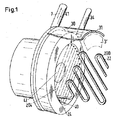
本発明による装置1を、図1から図4を参照しながら説明する。液体8と熱輸送媒体7との熱交換を液体8の静的混合と組み合わせるこの装置1は、固定構造体2と、液体8を案内する管状ハウジング3’を有するジャケット3とを含む。処理される液体8は通常、少なくとも1Pa・sの比較的高い絶対粘度を有し、装置1の重要な応用例では、例えば5000000Pa(50bar)の圧力を有するポリマー融成物である。
A device 1 according to the invention will be described with reference to FIGS. This device 1, which combines the heat exchange between the liquid 8 and the
ジャケット3は、ヘッド側端部4とベース側端部5の間に長手方向に延びている。固定構造体2は、「熱交換および混合」構造体を形成する。熱輸送媒体7は、固定構造体2の管21、22内部流として、ベース側端部5からヘッド側端部4へと流れる。液体8は、外部流としてヘッド側端部4からベース側端部5へと流れる。補強要素6(図2および図4参照)が設けられており、この補強要素6は固定構造体2を、液体8により生成される圧力勾配に逆らって長手方向に固定する。複数の固定構造体2が主要区域で補強要素6によって連結されて、伸張不可能部構造体2aを形成する。主要区域を補完する2次区域では、それら固定構造体2は補強されないままであり、または部分的にのみ補強されており、それにより、柔軟な長手方向伸張可能部構造体2bが形成される(一点鎖線で縁取られた矩形)。この柔軟部構造体2bがあるおかげで、膨張補償がもたらされる。膨張補償は、例えば装置の始動時などに生じる固定構造体2とハウジング3’の熱膨張が異なるために必要である。
The
本発明による装置1では、1つのステップで、すなわち対向流において熱交換が行われる。対向流では、知られているように、内部流と外部流の間で生じる平均温度差が、並行流におけるよりも大きい。結果的に、知られている重合反応器の多数ステップの熱交換よりも効率的に、熱交換を実施することができる。従って、2mの長さを有するそのような反応器を、例えば約35cm短い対向流反応器で置き換えることができる(両方の反応器は同じ断面積および同じ冷却能力を有する)。同時に、内部流(伝熱オイルの形態の熱キャリヤ)の圧力損失が半減される。 In the device 1 according to the invention, heat exchange takes place in one step, i.e. in the counterflow. In counterflow, as is known, the average temperature difference that occurs between the internal and external flows is greater than in parallel flows. As a result, heat exchange can be carried out more efficiently than the multi-step heat exchange of known polymerization reactors. Thus, such a reactor having a length of 2 m can be replaced by a counter-flow reactor, for example about 35 cm shorter (both reactors have the same cross-sectional area and the same cooling capacity). At the same time, the pressure loss of the internal flow (heat carrier in the form of heat transfer oil) is halved.
熱交換器/混合管、すなわち固定構造体2の管21、22は、平行に配置された平坦な層200を形成しており、その横方向の整合位置が、図1に一点鎖線204で示されている。各層200において、管22(または21)は、弧201および平行部分管部片202を含み、ベース側端部5にある入口端部25からヘッド側端部4にある出口端部24へと蛇状に延びている。隣接する層200の部分管部片202は、交差点203で交差する。図3では、2つの隣接する管21および22を左側に示し、管21のみを右側に示している。
The heat exchanger / mixing tubes, i.e. the
固定構造体2の主要区域では、2つの隣接する層200の管21および22は、補強要素6の有利な一実施例を形成するバー6’であって、軸線方向すなわち長手方向に位置合せされたバー6’上に締結される。バー6’は、ベース側端部5に締結され、膨張補償を可能にする柔軟部構造体2bまで、非柔軟部構造体2aにわたって延びている。バー6’がヘッド側端部4に締結され、柔軟部構造体2bがベース側端部5に配置される実施例も可能である。
In the main area of the
補強要素6は有利には、複数の箇所に分布するように配置された帯状プレート(図示せず)、バー6’(図2)、または連結部片6”(図4)として形成される。帯状プレートは、明らかにバーセクションと同等に製作された補強要素6であって、しかし図4の連結部片6”と同様の分布態様で配置された補強要素6として理解される。バー6’またはプレート上に、管21および22を挿入するための溝状の凹部が設けられ、それにより、そのプレートによって連結された管は互いに接触し、または、プレートの厚さよりも実質的に小さい比較的小さい間隔で配列される。管とプレートの間、または管とバー6’の間の締結連結部は、好ましくは、はんだ炉内ではんだ付けによって構築される。連結部は当然、溶接によって構築することもできる。図4に示される補強形態では、連結部片6’がそれぞれ、2つの隣接する部分管部片202に接触している。それらは、好ましくは溶接で取り付けられる。
The reinforcing element 6 is advantageously formed as a strip-like plate (not shown), a bar 6 ′ (FIG. 2) or a connecting piece 6 ″ (FIG. 4) arranged to be distributed at a plurality of locations. A strip-shaped plate is clearly understood as a reinforcing element 6 made in the same way as a bar section, but arranged in a distributed manner similar to the connecting piece 6 '' of FIG. On the bar 6 'or the plate, a groove-like recess for inserting the
流れ抵抗により、外部流内で装置の端部間に少なくとも10bar、好ましくは40barの長手方向の圧力差が生じるときに固定構造体が損なわれずに維持されるように、主要区域の非柔軟部構造体2aに十分な耐久性が与えられる。 Non-flexible structure of the main section so that the flow structure allows the fixed structure to remain intact when a longitudinal pressure difference of at least 10 bar, preferably 40 bar, occurs between the ends of the device in the external flow Sufficient durability is given to the body 2a.
本発明による装置1は、原則的に、ヘッド側端部4およびベース側端部5がそれぞれ、ジャケット3および固定構造体2に解放不可能に連結されるように設計される。この場合、固定構造体2は取り外すことができない。取外し可能な固定構造体2が必要とされる場合、既に知られている装置(重合反応器)を使用する方が有利となる可能性がある。
The device 1 according to the invention is designed in principle such that the head end 4 and the
ジャケット3は、外壁30と管状ハウジング3’との間に、環状間隙空間31を含むことができ、好ましくは熱輸送媒体7の一部である熱キャリヤを、前記環状間隙空間(熱キャリヤの入口ライン35および出口ライン34)を通して案内することができる。
The
熱交換器/混合管21、22は、ボアすなわち穴40内でヘッド側端部4に、および穴50内でベース側端部5に、取り付けられ締結される。穴40は、ジャケット付近の2つの環状セグメント上に配列され、穴50は、ベース側端部5の中央を横断する帯上に配列される。熱輸送媒体7は、入口ライン51および分配チャンバ517を通して、固定構造体2の個々の管21、22内に供給され、収集チャンバ417内のそれらの出口および出口ライン41にて組み合わされる。
The heat exchanger /
ヘッド側端部4は、中央入口開口42を有し、ベース側端部5は、中央に隣接配置された液体8用の出口開口52を有する。また、両方の開口42および52を中央に、または偏心して配置することができ、あるいは、入口開口42を偏心させ、出口開口52を中央にすることができる。
The head side end 4 has a
本発明による装置1は、冷却によって分解を最低限に抑えるために、例えばポリエステル融成物または別の融解ポリマー(液体8)のために使用することができる。別の用途は、ポリマーをより流動可能にするためのポリマーの加熱である。別の用途は、多量のチョコレート、キャラメル、またはチューイング・ガムなど、食品分野における高粘度媒体の加熱または冷却である。一般に、伝熱オイルが熱輸送媒体7として使用される。水または蒸気など、その他の媒体を使用することもできる。
The device 1 according to the invention can be used, for example, for polyester melts or other molten polymers (liquid 8) in order to minimize degradation by cooling. Another application is heating the polymer to make it more flowable. Another application is the heating or cooling of high viscosity media in the food sector, such as large amounts of chocolate, caramel, or chewing gum. In general, heat transfer oil is used as the
Claims (8)
複数の固定構造体(2)が、ヘッド側端部(4)とベース側端部(5)の間に長手方向に延びるジャケット(3)内に熱交換および混合構造体を形成し、
前記熱輸送媒体は、前記ベース側端部から前記ヘッド側端部へと前記固定構造体の複数の管(21、22)内で内部流として運ばれることができ、
前記液体は、前記ヘッド側端部から前記ベース側端部へと外部流として運ばれることができ、
前記液体によって生み出される圧力勾配に抗して前記固定構造体を前記長手方向に固定する複数の補強要素(6、6、6”)が設けられ、
前記固定構造体は、主要区域内で前記補強要素によって連結されて伸張不可能部分構造体(2a)を形成し、また主要区域を補足する2次区域内で少なくとも部分的に補強されずに長手方向伸張可能部分構造体(2b)となり、
前記管(21、22)がそれぞれ、隣接する管と平行な平坦な層(200)を形成し、且つ、弧(201)および平行部分管部片(202)を画定するように該管の入口端部(25)から出口端部(24)へと蛇行状に延び、
隣接する層の前記部分管部片が交差し、また
前記固定構造体(2)の前記主要区域は、少なくとも10bar、好ましくは40barの前記装置の端部間の長手方向の圧力差で前記固定構造体が損傷を受けないままであるような耐久性を与えられている
ことを特徴とする装置。 An apparatus (1) for combining heat transfer between a liquid (8) and a heat transport medium (7) with static mixing of said liquid,
A plurality of fixed structures (2) form a heat exchange and mixing structure in a jacket (3) extending longitudinally between the head side end (4) and the base side end (5);
The heat transport medium can be carried as an internal flow within the plurality of tubes (21, 22) of the fixed structure from the base side end to the head side end,
The liquid can be carried as an external flow from the head side end to the base side end,
A plurality of reinforcing elements (6, 6, 6 ″) are provided for fixing the fixing structure in the longitudinal direction against the pressure gradient created by the liquid;
The fixing structure is connected by the reinforcing element in the main area to form an inextensible substructure (2a) and is at least partially unreinforced in the secondary area that complements the main area. A directional stretchable substructure (2b),
Each of the tubes (21, 22) forms a flat layer (200) parallel to the adjacent tube and defines an arc (201) and a parallel partial tube piece (202). Extending in a meandering manner from the end (25) to the outlet end (24) ,
The partial tube pieces of adjacent layers intersect, and
The main area of the anchoring structure (2) is durable so that the anchoring structure remains undamaged by a longitudinal pressure difference between the ends of the device of at least 10 bar, preferably 40 bar. A device characterized in that it is given .
非中央または中央開口(42、52)が両方の端部(4、5)に配置されることを特徴とする、請求項1から請求項6までのいずれか一項に記載の装置。7. A device according to any one of the preceding claims, characterized in that non-central or central openings (42, 52) are arranged at both ends (4, 5).
前記融成物が、例えば分解を最低限に抑えるために冷却され、または、例えば前記ポリマーをより流動可能にするために加熱されることThe melt is cooled, for example, to minimize degradation, or heated, for example, to make the polymer more flowable
を特徴とする、請求項1から請求項7までのいずれか一項に記載の装置(1)の使用。Use of the device (1) according to any one of claims 1 to 7, characterized in that
Applications Claiming Priority (3)
| Application Number | Priority Date | Filing Date | Title |
|---|---|---|---|
| EP06118609.4 | 2006-08-08 | ||
| EP06118609 | 2006-08-08 | ||
| PCT/EP2007/057268 WO2008017571A1 (en) | 2006-08-08 | 2007-07-13 | Apparatus for combined heat transfer and static mixing with a liquid |
Related Child Applications (1)
| Application Number | Title | Priority Date | Filing Date |
|---|---|---|---|
| JP2013058002A Division JP2013117376A (en) | 2006-08-08 | 2013-03-21 | Apparatus for combined heat exchange and static mixing using liquid |
Publications (2)
| Publication Number | Publication Date |
|---|---|
| JP2010500526A JP2010500526A (en) | 2010-01-07 |
| JP5523097B2 true JP5523097B2 (en) | 2014-06-18 |
Family
ID=37533137
Family Applications (2)
| Application Number | Title | Priority Date | Filing Date |
|---|---|---|---|
| JP2009523232A Active JP5523097B2 (en) | 2006-08-08 | 2007-07-13 | Apparatus for performing combined heat exchange and static mixing with liquids |
| JP2013058002A Pending JP2013117376A (en) | 2006-08-08 | 2013-03-21 | Apparatus for combined heat exchange and static mixing using liquid |
Family Applications After (1)
| Application Number | Title | Priority Date | Filing Date |
|---|---|---|---|
| JP2013058002A Pending JP2013117376A (en) | 2006-08-08 | 2013-03-21 | Apparatus for combined heat exchange and static mixing using liquid |
Country Status (12)
| Country | Link |
|---|---|
| US (1) | US7997327B2 (en) |
| EP (1) | EP2052199B1 (en) |
| JP (2) | JP5523097B2 (en) |
| KR (1) | KR101495687B1 (en) |
| CN (1) | CN101506609B (en) |
| BR (1) | BRPI0714774B1 (en) |
| CA (1) | CA2660177C (en) |
| ES (1) | ES2668360T3 (en) |
| PL (1) | PL2052199T3 (en) |
| RU (1) | RU2433367C2 (en) |
| TW (1) | TWI461237B (en) |
| WO (1) | WO2008017571A1 (en) |
Families Citing this family (14)
| Publication number | Priority date | Publication date | Assignee | Title |
|---|---|---|---|---|
| TWI404903B (en) * | 2007-03-09 | 2013-08-11 | Sulzer Chemtech Ag | An apparatus for the heat-exchanging and mixing treatment of fluid media |
| CN101738122B (en) * | 2009-12-14 | 2011-12-21 | 杭州沈氏换热器有限公司 | Coiled tube and heat exchanger applying same |
| FR2963091B1 (en) * | 2010-07-20 | 2012-08-17 | Univ Savoie | FLUID CIRCULATION MODULE |
| CN102322752B (en) * | 2011-08-01 | 2013-05-22 | 西安交通大学 | Heat exchanger |
| EP2565572A1 (en) * | 2011-09-02 | 2013-03-06 | Aurotec GmbH | Heat exchange conduit system |
| BE1020321A3 (en) * | 2011-10-19 | 2013-08-06 | Atlas Copco Airpower Nv | TUBE HEAT EXCHANGER AND COMPRESSOR UNIT EQUIPPED. |
| EP2596860A1 (en) * | 2011-11-25 | 2013-05-29 | Fluitec Invest AG | Loop-type reactor fitted with a heat exchanger |
| US9777973B2 (en) | 2013-09-20 | 2017-10-03 | Promix Solutions Ag | Device for mixing and heat exchange |
| US11150037B2 (en) * | 2014-10-10 | 2021-10-19 | Baltimore Aircoil Company, Inc. | Heat exchange apparatus |
| MX2018009116A (en) | 2016-01-29 | 2018-09-10 | Basf Se | Hollow chamber x-mixer heat exchanger. |
| US10329985B2 (en) | 2017-06-27 | 2019-06-25 | Tenneco Automotive Operating Company Inc. | Impingement mixer for exhaust treatment |
| KR102037180B1 (en) * | 2018-01-04 | 2019-10-28 | 박동수 | Heat exchanger for internal heating |
| EP3620230A1 (en) | 2018-09-07 | 2020-03-11 | Fluitec Invest AG | Device of a chemical reactor and a method |
| EP4059979A1 (en) | 2021-03-18 | 2022-09-21 | Sulzer Management AG | A process of continuously manufacturing a poly(hydroxy acid) homo- or copolymer with tunable molecular weight, structure and composition |
Family Cites Families (18)
| Publication number | Priority date | Publication date | Assignee | Title |
|---|---|---|---|---|
| CH420230A (en) * | 1964-09-03 | 1966-09-15 | Sulzer Ag | Heat exchanger |
| CH428813A (en) * | 1965-01-21 | 1967-01-31 | Sulzer Ag | Heat exchanger |
| GB1376330A (en) * | 1972-12-29 | 1974-12-04 | British Nuclear Design Constr | Heat exchangers |
| JPS50138671U (en) * | 1974-04-30 | 1975-11-14 | ||
| DE2613745A1 (en) * | 1976-03-31 | 1977-10-06 | Linde Ag | HEAT EXCHANGER |
| DE2839563A1 (en) * | 1978-09-12 | 1980-03-27 | Hoechst Ag | METHOD FOR CONTINUOUS MASS POLYMERIZATION OF ALKENYL FLAVORS |
| DE8202599U1 (en) * | 1982-02-02 | 1982-06-24 | Bayer Ag, 5090 Leverkusen | DEVICE FOR MIXING AND / OR TEMPERATURE VISCOSE MEDIA |
| US4421070A (en) * | 1982-06-25 | 1983-12-20 | Combustion Engineering, Inc. | Steam cooled hanger tube for horizontal superheaters and reheaters |
| JPS60101593U (en) * | 1983-12-19 | 1985-07-11 | 千代田化工建設株式会社 | Vibration isolation structure for the bent part of the U-shaped tube for a U-shaped multi-tube heat exchanger |
| JPS6334484A (en) * | 1986-07-29 | 1988-02-15 | Mitsubishi Heavy Ind Ltd | Shell and tube type heat exchanger |
| US4865460A (en) | 1988-05-02 | 1989-09-12 | Kama Corporation | Static mixing device |
| JPH08261670A (en) * | 1992-04-10 | 1996-10-11 | Yamaura:Kk | Multi-drum type disassembled heat-exchanger |
| JP3309502B2 (en) * | 1993-07-12 | 2002-07-29 | 大日本インキ化学工業株式会社 | Continuous production method of biodegradable polyester polymer |
| EP0776692B1 (en) * | 1995-12-01 | 1999-08-11 | Dow Corning Corporation | Fluidized-bed reactor |
| SE515128C2 (en) * | 1997-06-03 | 2001-06-11 | Kanthal Ab | Method of heat treatment as well as a furnace bottom structure for high temperature furnaces |
| JP2003292594A (en) * | 2002-02-01 | 2003-10-15 | Kubota Corp | Method for producing polyester resin |
| CA2491755C (en) * | 2002-07-15 | 2010-06-22 | Sulzer Chemtech Usa, Inc. | Assembly of crossing elements and method of constructing same |
| DE102004045638A1 (en) * | 2004-09-21 | 2006-04-06 | Bayerische Motoren Werke Ag | Heat exchanger for hydrogen-powered fuel supply systems |
-
2007
- 2007-07-09 TW TW096124933A patent/TWI461237B/en active
- 2007-07-13 BR BRPI0714774-0A patent/BRPI0714774B1/en active IP Right Grant
- 2007-07-13 CA CA2660177A patent/CA2660177C/en active Active
- 2007-07-13 KR KR1020097002501A patent/KR101495687B1/en active IP Right Grant
- 2007-07-13 CN CN2007800296738A patent/CN101506609B/en active Active
- 2007-07-13 RU RU2009108295/06A patent/RU2433367C2/en active
- 2007-07-13 WO PCT/EP2007/057268 patent/WO2008017571A1/en active Application Filing
- 2007-07-13 EP EP07787536.7A patent/EP2052199B1/en active Active
- 2007-07-13 US US12/308,214 patent/US7997327B2/en active Active
- 2007-07-13 PL PL07787536T patent/PL2052199T3/en unknown
- 2007-07-13 ES ES07787536.7T patent/ES2668360T3/en active Active
- 2007-07-13 JP JP2009523232A patent/JP5523097B2/en active Active
-
2013
- 2013-03-21 JP JP2013058002A patent/JP2013117376A/en active Pending
Also Published As
| Publication number | Publication date |
|---|---|
| BRPI0714774B1 (en) | 2019-11-12 |
| CA2660177C (en) | 2014-09-09 |
| ES2668360T3 (en) | 2018-05-17 |
| EP2052199B1 (en) | 2018-02-14 |
| RU2433367C2 (en) | 2011-11-10 |
| BRPI0714774A2 (en) | 2013-03-26 |
| TWI461237B (en) | 2014-11-21 |
| CN101506609A (en) | 2009-08-12 |
| CN101506609B (en) | 2011-08-31 |
| CA2660177A1 (en) | 2008-02-14 |
| KR101495687B1 (en) | 2015-02-25 |
| US7997327B2 (en) | 2011-08-16 |
| JP2010500526A (en) | 2010-01-07 |
| EP2052199A1 (en) | 2009-04-29 |
| US20090165994A1 (en) | 2009-07-02 |
| TW200824785A (en) | 2008-06-16 |
| WO2008017571A1 (en) | 2008-02-14 |
| JP2013117376A (en) | 2013-06-13 |
| RU2009108295A (en) | 2010-09-20 |
| PL2052199T3 (en) | 2018-08-31 |
| KR20090048446A (en) | 2009-05-13 |
Similar Documents
| Publication | Publication Date | Title |
|---|---|---|
| JP5523097B2 (en) | Apparatus for performing combined heat exchange and static mixing with liquids | |
| JP4430347B2 (en) | Mixer / heat exchanger | |
| US10386120B2 (en) | Shell and tube heat exchanger | |
| US6582667B1 (en) | Shell-and-tube reactor | |
| USRE48466E1 (en) | Modular reactor | |
| WO2014123152A1 (en) | Reactor | |
| JPH03502422A (en) | bundle tubular reactor | |
| JP2000037618A (en) | Static mixer apparatus | |
| KR20190039523A (en) | Supply outflow heat exchanger | |
| JP3917424B2 (en) | Polymer solution preheater and method for preheating such a solution | |
| KR20230051213A (en) | A device that mixes and disperses fluid media, performs reactions, and supplies and dissipates heat. | |
| US6938687B2 (en) | Apparatus for transfer of heat energy between a body surface and heat transfer fluid | |
| RU2292946C2 (en) | System for carrying out the exothermic reaction | |
| KR100591704B1 (en) | Process for producing gaseous product by catalytic gas phase reaction and apparatus for carrying out the process | |
| JP5829770B1 (en) | Shell and tube heat exchanger | |
| RU2699909C1 (en) | Heat exchanger | |
| RU2719242C1 (en) | Heat exchanger | |
| RU2699906C1 (en) | Heat exchanger | |
| EP2008048B1 (en) | Heat exchanger structure |
Legal Events
| Date | Code | Title | Description |
|---|---|---|---|
| A621 | Written request for application examination |
Free format text: JAPANESE INTERMEDIATE CODE: A621 Effective date: 20100212 |
|
| A977 | Report on retrieval |
Free format text: JAPANESE INTERMEDIATE CODE: A971007 Effective date: 20120301 |
|
| A131 | Notification of reasons for refusal |
Free format text: JAPANESE INTERMEDIATE CODE: A131 Effective date: 20120309 |
|
| A601 | Written request for extension of time |
Free format text: JAPANESE INTERMEDIATE CODE: A601 Effective date: 20120608 |
|
| A602 | Written permission of extension of time |
Free format text: JAPANESE INTERMEDIATE CODE: A602 Effective date: 20120615 |
|
| A521 | Request for written amendment filed |
Free format text: JAPANESE INTERMEDIATE CODE: A523 Effective date: 20120830 |
|
| A02 | Decision of refusal |
Free format text: JAPANESE INTERMEDIATE CODE: A02 Effective date: 20121120 |
|
| A521 | Request for written amendment filed |
Free format text: JAPANESE INTERMEDIATE CODE: A523 Effective date: 20130321 |
|
| A911 | Transfer to examiner for re-examination before appeal (zenchi) |
Free format text: JAPANESE INTERMEDIATE CODE: A911 Effective date: 20130402 |
|
| A912 | Re-examination (zenchi) completed and case transferred to appeal board |
Free format text: JAPANESE INTERMEDIATE CODE: A912 Effective date: 20130524 |
|
| A61 | First payment of annual fees (during grant procedure) |
Free format text: JAPANESE INTERMEDIATE CODE: A61 Effective date: 20140408 |
|
| R150 | Certificate of patent or registration of utility model |
Ref document number: 5523097 Country of ref document: JP Free format text: JAPANESE INTERMEDIATE CODE: R150 |
|
| R250 | Receipt of annual fees |
Free format text: JAPANESE INTERMEDIATE CODE: R250 |
|
| R250 | Receipt of annual fees |
Free format text: JAPANESE INTERMEDIATE CODE: R250 |
|
| R250 | Receipt of annual fees |
Free format text: JAPANESE INTERMEDIATE CODE: R250 |
|
| R250 | Receipt of annual fees |
Free format text: JAPANESE INTERMEDIATE CODE: R250 |
|
| S111 | Request for change of ownership or part of ownership |
Free format text: JAPANESE INTERMEDIATE CODE: R313113 |
|
| R350 | Written notification of registration of transfer |
Free format text: JAPANESE INTERMEDIATE CODE: R350 |
|
| R250 | Receipt of annual fees |
Free format text: JAPANESE INTERMEDIATE CODE: R250 |
|
| R250 | Receipt of annual fees |
Free format text: JAPANESE INTERMEDIATE CODE: R250 |
|
| R250 | Receipt of annual fees |
Free format text: JAPANESE INTERMEDIATE CODE: R250 |
|
| R250 | Receipt of annual fees |
Free format text: JAPANESE INTERMEDIATE CODE: R250 |