JP5520552B2 - Semiconductor device manufacturing method and substrate processing apparatus - Google Patents
Semiconductor device manufacturing method and substrate processing apparatus Download PDFInfo
- Publication number
- JP5520552B2 JP5520552B2 JP2009210590A JP2009210590A JP5520552B2 JP 5520552 B2 JP5520552 B2 JP 5520552B2 JP 2009210590 A JP2009210590 A JP 2009210590A JP 2009210590 A JP2009210590 A JP 2009210590A JP 5520552 B2 JP5520552 B2 JP 5520552B2
- Authority
- JP
- Japan
- Prior art keywords
- inert gas
- substrate processing
- processing chamber
- gas
- gas supply
- Prior art date
- Legal status (The legal status is an assumption and is not a legal conclusion. Google has not performed a legal analysis and makes no representation as to the accuracy of the status listed.)
- Active
Links
Images


Classifications
-
- C—CHEMISTRY; METALLURGY
- C23—COATING METALLIC MATERIAL; COATING MATERIAL WITH METALLIC MATERIAL; CHEMICAL SURFACE TREATMENT; DIFFUSION TREATMENT OF METALLIC MATERIAL; COATING BY VACUUM EVAPORATION, BY SPUTTERING, BY ION IMPLANTATION OR BY CHEMICAL VAPOUR DEPOSITION, IN GENERAL; INHIBITING CORROSION OF METALLIC MATERIAL OR INCRUSTATION IN GENERAL
- C23C—COATING METALLIC MATERIAL; COATING MATERIAL WITH METALLIC MATERIAL; SURFACE TREATMENT OF METALLIC MATERIAL BY DIFFUSION INTO THE SURFACE, BY CHEMICAL CONVERSION OR SUBSTITUTION; COATING BY VACUUM EVAPORATION, BY SPUTTERING, BY ION IMPLANTATION OR BY CHEMICAL VAPOUR DEPOSITION, IN GENERAL
- C23C16/00—Chemical coating by decomposition of gaseous compounds, without leaving reaction products of surface material in the coating, i.e. chemical vapour deposition [CVD] processes
- C23C16/22—Chemical coating by decomposition of gaseous compounds, without leaving reaction products of surface material in the coating, i.e. chemical vapour deposition [CVD] processes characterised by the deposition of inorganic material, other than metallic material
- C23C16/30—Deposition of compounds, mixtures or solid solutions, e.g. borides, carbides, nitrides
- C23C16/34—Nitrides
-
- C—CHEMISTRY; METALLURGY
- C23—COATING METALLIC MATERIAL; COATING MATERIAL WITH METALLIC MATERIAL; CHEMICAL SURFACE TREATMENT; DIFFUSION TREATMENT OF METALLIC MATERIAL; COATING BY VACUUM EVAPORATION, BY SPUTTERING, BY ION IMPLANTATION OR BY CHEMICAL VAPOUR DEPOSITION, IN GENERAL; INHIBITING CORROSION OF METALLIC MATERIAL OR INCRUSTATION IN GENERAL
- C23C—COATING METALLIC MATERIAL; COATING MATERIAL WITH METALLIC MATERIAL; SURFACE TREATMENT OF METALLIC MATERIAL BY DIFFUSION INTO THE SURFACE, BY CHEMICAL CONVERSION OR SUBSTITUTION; COATING BY VACUUM EVAPORATION, BY SPUTTERING, BY ION IMPLANTATION OR BY CHEMICAL VAPOUR DEPOSITION, IN GENERAL
- C23C16/00—Chemical coating by decomposition of gaseous compounds, without leaving reaction products of surface material in the coating, i.e. chemical vapour deposition [CVD] processes
- C23C16/44—Chemical coating by decomposition of gaseous compounds, without leaving reaction products of surface material in the coating, i.e. chemical vapour deposition [CVD] processes characterised by the method of coating
- C23C16/455—Chemical coating by decomposition of gaseous compounds, without leaving reaction products of surface material in the coating, i.e. chemical vapour deposition [CVD] processes characterised by the method of coating characterised by the method used for introducing gases into reaction chamber or for modifying gas flows in reaction chamber
- C23C16/45523—Pulsed gas flow or change of composition over time
- C23C16/45525—Atomic layer deposition [ALD]
- C23C16/45527—Atomic layer deposition [ALD] characterized by the ALD cycle, e.g. different flows or temperatures during half-reactions, unusual pulsing sequence, use of precursor mixtures or auxiliary reactants or activations
- C23C16/45534—Use of auxiliary reactants other than used for contributing to the composition of the main film, e.g. catalysts, activators or scavengers
-
- C—CHEMISTRY; METALLURGY
- C23—COATING METALLIC MATERIAL; COATING MATERIAL WITH METALLIC MATERIAL; CHEMICAL SURFACE TREATMENT; DIFFUSION TREATMENT OF METALLIC MATERIAL; COATING BY VACUUM EVAPORATION, BY SPUTTERING, BY ION IMPLANTATION OR BY CHEMICAL VAPOUR DEPOSITION, IN GENERAL; INHIBITING CORROSION OF METALLIC MATERIAL OR INCRUSTATION IN GENERAL
- C23C—COATING METALLIC MATERIAL; COATING MATERIAL WITH METALLIC MATERIAL; SURFACE TREATMENT OF METALLIC MATERIAL BY DIFFUSION INTO THE SURFACE, BY CHEMICAL CONVERSION OR SUBSTITUTION; COATING BY VACUUM EVAPORATION, BY SPUTTERING, BY ION IMPLANTATION OR BY CHEMICAL VAPOUR DEPOSITION, IN GENERAL
- C23C16/00—Chemical coating by decomposition of gaseous compounds, without leaving reaction products of surface material in the coating, i.e. chemical vapour deposition [CVD] processes
- C23C16/44—Chemical coating by decomposition of gaseous compounds, without leaving reaction products of surface material in the coating, i.e. chemical vapour deposition [CVD] processes characterised by the method of coating
- C23C16/455—Chemical coating by decomposition of gaseous compounds, without leaving reaction products of surface material in the coating, i.e. chemical vapour deposition [CVD] processes characterised by the method of coating characterised by the method used for introducing gases into reaction chamber or for modifying gas flows in reaction chamber
- C23C16/45523—Pulsed gas flow or change of composition over time
- C23C16/45525—Atomic layer deposition [ALD]
- C23C16/45544—Atomic layer deposition [ALD] characterized by the apparatus
- C23C16/45546—Atomic layer deposition [ALD] characterized by the apparatus specially adapted for a substrate stack in the ALD reactor
-
- C—CHEMISTRY; METALLURGY
- C23—COATING METALLIC MATERIAL; COATING MATERIAL WITH METALLIC MATERIAL; CHEMICAL SURFACE TREATMENT; DIFFUSION TREATMENT OF METALLIC MATERIAL; COATING BY VACUUM EVAPORATION, BY SPUTTERING, BY ION IMPLANTATION OR BY CHEMICAL VAPOUR DEPOSITION, IN GENERAL; INHIBITING CORROSION OF METALLIC MATERIAL OR INCRUSTATION IN GENERAL
- C23C—COATING METALLIC MATERIAL; COATING MATERIAL WITH METALLIC MATERIAL; SURFACE TREATMENT OF METALLIC MATERIAL BY DIFFUSION INTO THE SURFACE, BY CHEMICAL CONVERSION OR SUBSTITUTION; COATING BY VACUUM EVAPORATION, BY SPUTTERING, BY ION IMPLANTATION OR BY CHEMICAL VAPOUR DEPOSITION, IN GENERAL
- C23C16/00—Chemical coating by decomposition of gaseous compounds, without leaving reaction products of surface material in the coating, i.e. chemical vapour deposition [CVD] processes
- C23C16/44—Chemical coating by decomposition of gaseous compounds, without leaving reaction products of surface material in the coating, i.e. chemical vapour deposition [CVD] processes characterised by the method of coating
- C23C16/455—Chemical coating by decomposition of gaseous compounds, without leaving reaction products of surface material in the coating, i.e. chemical vapour deposition [CVD] processes characterised by the method of coating characterised by the method used for introducing gases into reaction chamber or for modifying gas flows in reaction chamber
- C23C16/45557—Pulsed pressure or control pressure
-
- C—CHEMISTRY; METALLURGY
- C23—COATING METALLIC MATERIAL; COATING MATERIAL WITH METALLIC MATERIAL; CHEMICAL SURFACE TREATMENT; DIFFUSION TREATMENT OF METALLIC MATERIAL; COATING BY VACUUM EVAPORATION, BY SPUTTERING, BY ION IMPLANTATION OR BY CHEMICAL VAPOUR DEPOSITION, IN GENERAL; INHIBITING CORROSION OF METALLIC MATERIAL OR INCRUSTATION IN GENERAL
- C23C—COATING METALLIC MATERIAL; COATING MATERIAL WITH METALLIC MATERIAL; SURFACE TREATMENT OF METALLIC MATERIAL BY DIFFUSION INTO THE SURFACE, BY CHEMICAL CONVERSION OR SUBSTITUTION; COATING BY VACUUM EVAPORATION, BY SPUTTERING, BY ION IMPLANTATION OR BY CHEMICAL VAPOUR DEPOSITION, IN GENERAL
- C23C16/00—Chemical coating by decomposition of gaseous compounds, without leaving reaction products of surface material in the coating, i.e. chemical vapour deposition [CVD] processes
- C23C16/44—Chemical coating by decomposition of gaseous compounds, without leaving reaction products of surface material in the coating, i.e. chemical vapour deposition [CVD] processes characterised by the method of coating
- C23C16/455—Chemical coating by decomposition of gaseous compounds, without leaving reaction products of surface material in the coating, i.e. chemical vapour deposition [CVD] processes characterised by the method of coating characterised by the method used for introducing gases into reaction chamber or for modifying gas flows in reaction chamber
- C23C16/45561—Gas plumbing upstream of the reaction chamber
-
- H—ELECTRICITY
- H10—SEMICONDUCTOR DEVICES; ELECTRIC SOLID-STATE DEVICES NOT OTHERWISE PROVIDED FOR
- H10P—GENERIC PROCESSES OR APPARATUS FOR THE MANUFACTURE OR TREATMENT OF DEVICES COVERED BY CLASS H10
- H10P14/00—Formation of materials, e.g. in the shape of layers or pillars
- H10P14/20—Formation of materials, e.g. in the shape of layers or pillars of semiconductor materials
- H10P14/24—Formation of materials, e.g. in the shape of layers or pillars of semiconductor materials using chemical vapour deposition [CVD]
-
- H—ELECTRICITY
- H10—SEMICONDUCTOR DEVICES; ELECTRIC SOLID-STATE DEVICES NOT OTHERWISE PROVIDED FOR
- H10P—GENERIC PROCESSES OR APPARATUS FOR THE MANUFACTURE OR TREATMENT OF DEVICES COVERED BY CLASS H10
- H10P14/00—Formation of materials, e.g. in the shape of layers or pillars
- H10P14/40—Formation of materials, e.g. in the shape of layers or pillars of conductive or resistive materials
- H10P14/42—Formation of materials, e.g. in the shape of layers or pillars of conductive or resistive materials using a gas or vapour
- H10P14/43—Chemical deposition, e.g. chemical vapour deposition [CVD]
- H10P14/432—Chemical deposition, e.g. chemical vapour deposition [CVD] using selective deposition
-
- H—ELECTRICITY
- H10—SEMICONDUCTOR DEVICES; ELECTRIC SOLID-STATE DEVICES NOT OTHERWISE PROVIDED FOR
- H10W—GENERIC PACKAGES, INTERCONNECTIONS, CONNECTORS OR OTHER CONSTRUCTIONAL DETAILS OF DEVICES COVERED BY CLASS H10
- H10W20/00—Interconnections in chips, wafers or substrates
- H10W20/01—Manufacture or treatment
- H10W20/031—Manufacture or treatment of conductive parts of the interconnections
- H10W20/032—Manufacture or treatment of conductive parts of the interconnections of conductive barrier, adhesion or liner layers
- H10W20/033—Manufacture or treatment of conductive parts of the interconnections of conductive barrier, adhesion or liner layers in openings in dielectrics
Landscapes
- Chemical & Material Sciences (AREA)
- General Chemical & Material Sciences (AREA)
- Chemical Kinetics & Catalysis (AREA)
- Engineering & Computer Science (AREA)
- Materials Engineering (AREA)
- Mechanical Engineering (AREA)
- Metallurgy (AREA)
- Organic Chemistry (AREA)
- Inorganic Chemistry (AREA)
- Chemical Vapour Deposition (AREA)
Description
本発明は、例えば、半導体集積回路装置(以下、ICという。)等の半導体装置(半導体デバイス)の製造方法において、IC等が作り込まれる半導体ウエハ(以下、ウエハという。)等の基板に所望の膜を形成するための、基板処理装置及びIC等の半導体装置の製造方法に関する。 The present invention is desired for a substrate such as a semiconductor wafer (hereinafter referred to as a wafer) in which an IC or the like is manufactured in a method for manufacturing a semiconductor device (semiconductor device) such as a semiconductor integrated circuit device (hereinafter referred to as an IC). The present invention relates to a substrate processing apparatus and a method for manufacturing a semiconductor device such as an IC for forming the film.
ICの製造方法においては、膜を形成するのにバッチ式縦型成膜装置が使用されることがある。例えば、特許文献1には、半導体デバイス製造プロセスで、例えば、ALD法によりアミン系材料を用いて成膜を行う場合、TiNの成膜では、Ti(チタン)のソースとN(窒素)のソースとを処理室内の半導体シリコン基板上に交互に供給するが、TiのソースからNのソースに切り替える際には、Tiのソースを処理室から除去するためにH2(水素)を用いてパージを行い、または、その逆のNのソースからTiのソースに切り替える際には、Nのソースを処理室から除去するためにH2を用いてパージを行うことが開示されている。
In an IC manufacturing method, a batch type vertical film forming apparatus may be used to form a film. For example, in
例えば、基板の収容された処理室内に、原料Aと原料Bを交互に供給し、基板上に原料分子を吸着させて成膜を行う基板処理装置においては、一方の原料を供給した後、次に他方の原料を供給する前に、前記一方の原料を処理室内及び基板表面から除去する必要がある。原料を処理室内等から除去するために、従来では、処理室内を排気しつつ、H2(水素)やN2(窒素)等の不活性ガスを連続的に、又は間欠的に処理室内に供給する方法を用いていた。しかし、この方法では、基板表面等に吸着した余分な原料分子を除去するために長時間を要し、結果として、生産性の低下の原因となっていた。また、従来のパージ方法では、パージ時間を短くするとパージ不足となり、結果、膜厚が厚くなってしまう。
本発明の目的は、基板処理室内から余分な原料分子を、短時間で除去することができる半導体装置の製造方法及び基板処理装置を提供することにある。
For example, in a substrate processing apparatus in which a raw material A and a raw material B are alternately supplied into a processing chamber in which a substrate is accommodated, and a raw material molecule is adsorbed on the substrate to form a film, Before supplying the other material to the substrate, it is necessary to remove the one material from the processing chamber and the substrate surface. Conventionally, an inert gas such as H 2 (hydrogen) or N 2 (nitrogen) is supplied into the processing chamber continuously or intermittently while exhausting the processing chamber in order to remove the raw material from the processing chamber. The method to use was used. However, in this method, it takes a long time to remove excess raw material molecules adsorbed on the substrate surface and the like, resulting in a decrease in productivity. Further, in the conventional purge method, if the purge time is shortened, the purge is insufficient, and as a result, the film thickness is increased.
An object of the present invention is to provide a method of manufacturing a semiconductor device and a substrate processing apparatus capable of removing excess source molecules from the substrate processing chamber in a short time.
本発明においては、原料を処理室内等から除去する際に、パージ(除去)用不活性ガスを一旦、ガス溜め部に溜め、瞬時に基板処理室内へ供給する。このようにすると、パージ用不活性ガスは、高い運動エネルギを伴って、基板処理室内の基板や、基板処理室内壁等に吸着した原料ガスの分子と衝突する。この衝突により、基板等に物理的に吸着しているが化学結合していない状態の原料ガスの分子は、基板等から脱離する。
また、パージ用不活性ガスが、極めて短時間で基板処理室内へ供給されるので、不活性ガスを供給しつつ排気する従来のパージ方法よりも、基板処理室内の圧力が上昇し、基板表面に形成された溝や穴の奥まで、不活性ガス分子が到達して、溝部や穴部におけるパージ効果が高まる。物理的な吸着力は、膜表面に対する原料分子のファンデルワールス力に依存するので、基板処理室内の圧力をどの程度まで上昇させるかは、原料の種類、及び膜種により異なる。
具体的には、本発明の代表的な構成は、次のとおりである。
基板を収容した基板処理室内に、所定の元素を含む原料ガスを供給して、前記基板上に前記所定の元素を含む膜を形成する第1の工程と、
前記基板処理室内に不活性ガスを供給して、前記基板処理室内に残留する前記原料ガスを除去する第2の工程と、
前記基板処理室内に、前記所定の元素と反応する改質ガスを供給して、前記基板上に前記第1の工程により形成された所定の元素を含む膜を改質する第3の工程と、
前記基板処理室内に不活性ガスを供給して、前記基板処理室内に残留する前記改質ガスを除去する第4の工程と、
前記基板処理室に接続されたガス溜め部に不活性ガスを充填する不活性ガス充填工程とを備え、
前記第2の工程及び前記第4の工程の前に、前記不活性ガス充填工程を行い、
前記第2の工程及び前記第4の工程では、前記不活性ガス充填工程により前記ガス溜め部に充填された不活性ガスを、前記基板処理室内に供給することを特徴とする半導体装置の製造方法。
In the present invention, when the raw material is removed from the processing chamber or the like, a purge (removal) inert gas is temporarily stored in the gas reservoir and is instantaneously supplied into the substrate processing chamber. In this way, the purge inert gas collides with the molecules of the source gas adsorbed on the substrate in the substrate processing chamber, the wall of the substrate processing chamber, etc. with high kinetic energy. By this collision, the molecules of the source gas that are physically adsorbed on the substrate or the like but are not chemically bonded are desorbed from the substrate or the like.
In addition, since the inert gas for purging is supplied into the substrate processing chamber in an extremely short time, the pressure in the substrate processing chamber increases compared to the conventional purging method in which the inert gas is exhausted while supplying the inert gas. Inert gas molecules reach the back of the formed groove or hole, and the purge effect in the groove or hole is enhanced. Since the physical adsorption force depends on the van der Waals force of the raw material molecules on the film surface, the extent to which the pressure in the substrate processing chamber is raised differs depending on the kind of raw material and the film type.
Specifically, a typical configuration of the present invention is as follows.
A first step of forming a film containing the predetermined element on the substrate by supplying a source gas containing the predetermined element into a substrate processing chamber containing the substrate;
A second step of supplying an inert gas into the substrate processing chamber to remove the source gas remaining in the substrate processing chamber;
A third step of reforming a film containing the predetermined element formed on the substrate by the first step by supplying a reforming gas that reacts with the predetermined element into the substrate processing chamber;
A fourth step of supplying an inert gas into the substrate processing chamber to remove the reformed gas remaining in the substrate processing chamber;
An inert gas filling step of filling an inert gas into a gas reservoir connected to the substrate processing chamber,
Before the second step and the fourth step, perform the inert gas filling step,
In the second step and the fourth step, an inert gas filled in the gas reservoir in the inert gas filling step is supplied into the substrate processing chamber. .
上記の構成によれば、基板表面等に吸着した余分な原料分子を、短時間で除去することができ、生産性が向上する。また、短時間で十分なパージが可能となり、膜厚を薄くすることが容易となる。 According to said structure, the excess raw material molecule | numerator adsorb | sucked to the substrate surface etc. can be removed in a short time, and productivity improves. Further, a sufficient purge can be performed in a short time, and the film thickness can be easily reduced.
以下、本発明の実施例を、図面を用いて説明する。図1は、本発明の実施例に係るバッチ式縦型成膜装置の処理炉の垂直断面図である。図2は、本発明の実施例に係るバッチ式縦型成膜装置の処理炉の水平断面図である。図6は、本発明の実施例に係るバッチ式縦型成膜装置を示す斜視図である。
本実施例において、本発明に係る基板処理装置は、成膜に用いる2 種類( またはそれ以上) の原料となるガスを1 種類ずつ交互に基板上に供給し、1〜数原子層単位で吸着させ、表面反応により成膜を行う。
Embodiments of the present invention will be described below with reference to the drawings. FIG. 1 is a vertical sectional view of a processing furnace of a batch type vertical film forming apparatus according to an embodiment of the present invention. FIG. 2 is a horizontal sectional view of the processing furnace of the batch type vertical film forming apparatus according to the embodiment of the present invention. FIG. 6 is a perspective view showing a batch type vertical film forming apparatus according to an embodiment of the present invention.
In this embodiment, the substrate processing apparatus according to the present invention alternately supplies two kinds (or more) of raw material gases used for film formation onto the substrate one by one and adsorbs in units of one to several atomic layers. The film is formed by surface reaction.
[処理炉]
図1、図2および図6に示されているように、本実施例に係る基板処理装置100は、処理炉202を備えており、処理炉202は、石英製の反応管203を備えている。反応管203は、基板(本例ではウエハ200)を収容し、加熱処理する反応容器である。反応管203は、加熱部(本例では抵抗ヒータ207)の内側に設けられている。反応管203は、その下端開口をシールキャップ219により、気密部材(本例ではOリング220)を介して気密に閉塞される。
反応管203およびヒータ207の外側には、断熱部材208が設けられている。断熱部材208は、反応管203およびヒータ207の上方を覆うように設けられている。
ヒータ207、断熱部材208、反応管203およびシールキャップ219により、処理炉202が形成されている。また、反応管203、シールキャップ219、および反応管203内に形成されたバッファ室237により、基板処理室201が形成されている。シールキャップ219の上には、基板保持部材(ボート217)が、石英キャップ218を介して立設されている。石英キャップ218は、ボート217を保持する保持体である。ボート217は、処理炉202内に、処理炉202の下端開口から挿入される。ボート217には、バッチ処理される複数のウエハ200が、それぞれ水平姿勢で管軸方向(垂直方向)に多段に積載される。ヒータ207は、処理炉202に挿入されたウエハ200を、所定の温度に加熱する。
[Process furnace]
As shown in FIGS. 1, 2, and 6, the
A
A
[原料ガス供給部]
処理炉202には、複数(少なくとも2本)のガス供給管232a、232bが設けられている。2本のガス供給管232a、232bにより、互いに反応しあう少なくとも2種類の処理ガス(原料ガス)が、独立して、交互に処理炉202に供給される。
第1のガス供給管232bは、第1のガス供給源240bから、流量制御装置であるMFC(マスフローコントローラ)241b、開閉バルブ(開閉弁)243b、およびガス供給室249(図2参照)を介して、第1の処理ガスを基板処理室201に供給する。
第2のガス供給管232aは、第2のガス供給源240aから、MFC241a、開閉バルブ243a、および反応管203内に形成されたバッファ室237を介して、第2の処理ガスを基板処理室201に供給する。
上記の第1のガス供給源240b、MFC241b、ガス供給管232b等から、第1の原料ガス供給部が構成される。また、第2のガス供給源240a、MFC241a、ガス供給管232a等から、第2の原料ガス供給部が構成される。
[Raw gas supply section]
The
The first
The second
A first source gas supply unit is configured by the first
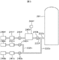
[不活性ガス供給部]
図1に示すように、第1のガス供給管232bの上流には、ガス供給管232fが接続されている。ガス供給管232fには、上流側から順に、第1の不活性ガス供給源240f、MFC241f、開閉バルブ243f、ガス溜め部245f、開閉バルブ243kが設けられている。ガス溜め部245fには、圧力センサ244fが設けられている。本例では、ガス溜め部245fの内径は、第1の不活性ガス供給源240fと開閉バルブ243fの間のガス供給管の内径、ガス溜め部245fと開閉バルブ243fの間のガス供給管の内径、ガス溜め部245fと開閉バルブ243kの間のガス供給管の内径、ガス供給管232fの内径、第1のガス供給管232bの内径のいずれよりも大きい。
第2のガス供給管232aの上流には、ガス供給管232eが接続されている。ガス供給管232eには、上流側から順に、第2の不活性ガス供給源240e、MFC241e、開閉バルブ243e、ガス溜め部245e、開閉バルブ243hが設けられている。ガス溜め部245eには、圧力センサ244eが設けられている。本例では、ガス溜め部245eの内径は、第2の不活性ガス供給源240eと開閉バルブ243eの間のガス供給管の内径、ガス溜め部245eと開閉バルブ243eの間のガス供給管の内径、ガス溜め部245eと開閉バルブ243hの間のガス供給管の内径、ガス供給管232eの内径、第2のガス供給管232aの内径のいずれよりも大きい。
なお、本実施例では、前記基板処理室201の容積と、前記ガス溜め部245fの容積との容積比、あるいは、前記基板処理室201の容積と、前記ガス溜め部245eの容積との容積比は、約200〜2000としている。
上記の第1の不活性ガス供給源240f、MFC241f、ガス供給管232b等から、あるいは、第2の不活性ガス供給源240e、MFC241e、ガス供給管232a等から、不活性ガス供給部が構成される。
[Inert gas supply unit]
As shown in FIG. 1, a
A
In this embodiment, the volume ratio between the volume of the
An inert gas supply unit is configured from the first inert
なお、図1においては、第1のガス供給管232bには、1本の不活性ガス供給管232fを接続し、第2のガス供給管232aには、1本の不活性ガス供給管232eを接続するようにしているが、第1のガス供給管232b及び第2のガス供給管232aに、それぞれ、複数の不活性ガス供給管を接続するようにしてもよい。例えば、第1のガス供給管232bの場合は、図4に示すように、第1のガス供給管232bに、複数の不活性ガス供給管232fと不活性ガス供給管232mを接続する、あるいは、図5に示すように、第1のガス供給管232bに、複数の不活性ガス供給管232fと不活性ガス供給管232nを接続するようにしてもよい。第2のガス供給管232aの場合も、第1のガス供給管232bの場合と同様である。図4は、本発明の実施例に係る不活性ガス供給ラインの1例を示す図である。図5は、本発明の実施例に係る不活性ガス供給ラインの他の例を示す図である。
In FIG. 1, one inert
図4においては、第1の不活性ガス供給源240fからの不活性ガス供給管を2つに分岐し、一方は開閉バルブ243fを介してガス溜め部245fへ、他方はMFC241mへ接続する。このようにすると、一方で、開閉バルブ243fを開き、開閉バルブ243kを閉じた状態で、ガス溜め部245fに不活性ガスを溜めつつ、他方で、開閉バルブ243mを開き、MFC241mで流量調整した不活性ガスを、第1のガス供給管232bに流し、基板処理室201へ供給することができる。
図5においては、第1の不活性ガス供給源240fとは別に、不活性ガス供給源240nを設け、該不活性ガス供給源240nを、MFC241n、開閉バルブ243nを介して、第1のガス供給管232bに接続している。図5に示す例においても、図4に示す例と同様に、一方で、開閉バルブ243fを開き、開閉バルブ243kを閉じた状態で、ガス溜め部245fに不活性ガスを溜めつつ、他方で、開閉バルブ243nを開き、MFC241nで流量調整した不活性ガスを、第1のガス供給管232bに流し、基板処理室201へ供給することができる。
In FIG. 4, the inert gas supply pipe from the first inert
In FIG. 5, an inert
図4及び図5に模式的に示すように、不活性ガス供給管232fの内径は、不活性ガス供給管232fと第1のガス供給管232bとの合流点より上流における、第1のガス供給管232bの内径よりも大きくすることが好ましい。このようにすると、ガス溜め部245fに溜めた不活性ガスを、短時間で、基板処理室201へ供給することが容易となる。不活性ガス供給管232eも同様である。
なお、上述したように本実施例では、ガス溜め部245f、245eの内径を、ガス供給管の内径よりも大きくしているが、ガス供給管の内径が十分大きい場合は、ガス溜めの内径をガス供給管の内径よりも大きくしなくてもよい。また、ガス溜め部は、第1のガス供給管232bや第2のガス供給管232aに接続せず、不活性ガス供給管232e、232fを直接、基板処理室201へ接続することもできる。
また、ガス溜め部は、複数設けるようにし、それぞれのガス溜め部から基板処理室201内へ不活性ガスを供給するようにしてもよい。あるいは、ガス溜め部は1つだけ設け、該ガス溜め部から基板処理室201内へ不活性ガスを供給するようにしてもよい。例えば、ガス溜め部245f、245eのうち、1つだけを設けるようにしてもよい。
As schematically shown in FIGS. 4 and 5, the inner diameter of the inert
As described above, in the present embodiment, the inner diameters of the
Further, a plurality of gas reservoirs may be provided, and an inert gas may be supplied from each gas reservoir into the
[クリーニングガス供給部]
第1のガス供給管232b及び第2のガス供給管232aには、クリーニングガス供給管232cが、それぞれ、開閉バルブ243cおよび開閉バルブ243dの下流側において接続されている。クリーニングガス供給管232cには、上流側から順に、第3のガス(クリーニングガス)供給源240c、MFC241c、開閉バルブ243c、又は開閉バルブ243dが設けられている。
ガス供給管232cは、第2のガス供給管232aおよび第1のガス供給管232bに接続されており、MFC241c、開閉バルブ243d、バッファ室237を介して、あるいは、MFC241c、開閉バルブ243c、ガス供給室249を介して、クリーニングガスを基板処理室201に供給する。
反応副生成物の付着を防ぐために、ガス供給管232a、232b、232cには、少なくとも120℃程度まで加熱可能な配管ヒータ(図示せず)が装着されている。
[Cleaning gas supply unit]
A cleaning gas supply pipe 232c is connected to the first
The gas supply pipe 232c is connected to the second
In order to prevent adhesion of reaction byproducts, the
[排気部]
基板処理室201には、基板処理室201内のガスを排気するガス排気管231の一端が接続されている。ガス排気管231の他端は、真空ポンプ246(排気装置)にAPC(Auto Pressure Controller)バルブ243gを介して接続されている。ガス排気管231は、複数の排気管を直列につなぎ合わせて一つの排気管としており、つなぎ合わせた箇所にはOリング234が設けられている。基板処理室201内は、真空ポンプ246によって排気される。
なお、APCバルブ243gは、弁の開閉により基板処理室201の排気および排気停止を行なうことができる開閉弁であり、かつまた、弁開度の調節により圧力を調整することができる圧力調整弁である。
反応副生成物の付着を防ぐために、ガス排気管231には、少なくとも150℃以上に加熱可能なヒータ247(排気管加熱部)が装着されている。ヒータ247は、コントローラ321によって制御される。
上記のガス排気管231、APCバルブ243g、真空ポンプ246等から、排気部が構成される。
[Exhaust section]
One end of a
The
In order to prevent adhesion of reaction by-products, the
The
[第1の原料ガス供給部]
図2に示すように、反応管203の内壁には、第1の処理ガスを供給するガス供給室249が設けられている。ガス供給室249は、反応管203下部より上部に亘って、反応管203の内壁に沿って、垂直方向(ウエハ200の積載方向)に設けられており、ガス分散空間を形成している。ガス供給室249は、後述する第2の処理ガスを供給するバッファ室237とは、別の独立した構造である。ガス供給室249は、ALD法による成膜において、ウエハ200へ、複数種類の処理ガスを1種類ずつ交互に供給する際に、前記バッファ室237とガス供給種を分担して供給する。
ガス供給室249は、複数のガス供給孔248cを有する。後述するバッファ室237のガス供給孔248aと同様に、ガス供給孔248cは、ウエハと隣接する位置に垂直方向に同一ピッチで設けられ、第1の処理ガスを供給する。ガス供給室249の下部には、第1のガス供給管232bが接続されている。
ガス供給孔248cの開口面積は、後述するバッファ室237のガス供給孔248aと同様に、ガス供給室249と基板処理室201の差圧が小さい場合、上流側から下流側まで同一の開口面積で同一の開口ピッチとするとよい。しかし、差圧が大きい場合、ガス供給孔248cの開口面積を、上流側から下流側に向かって開口面積を大きくするか、開口ピッチを小さくするとよい。
[First source gas supply unit]
As shown in FIG. 2, a
The
The opening area of the
[第2の原料ガス供給部]
図2に示すように、反応管203内壁には、第2の処理ガスを供給するバッファ室237が設けられている。バッファ室237は、反応管203下部より上部に亘って、反応管203の内壁に沿って、垂直方向(ウエハ200の積載方向)に設けられており、ガス分散空間を形成している。
図2に示すように、バッファ室237の内側壁部、すなわち、ウエハ200と隣接する側の壁の周方向における一端の近傍には、基板処理室201内にガスを供給するガス供給孔248aが設けられている。ガス供給孔248aは、ガス供給孔248cの位置から反応管203の内周を120度程度、時計回りに回った位置にある。ガス供給孔248aは、反応管203の中心(軸心)へ向けて開口している。ガス供給孔248aは、バッファ室237の下部から上部にかけ所定の長さ(所定長a)にわたって、垂直方向(ウエハ200の積載方向)に、それぞれ同一の開口面積を有し、同じ開口ピッチで設けられている。
[Second source gas supply unit]
As shown in FIG. 2, a
As shown in FIG. 2, a
バッファ室237において、ガス供給孔248aと周方向に反対側端部近傍には、ノズル233が反応管203の下部より上部にわたり、垂直方向(ウエハ200の積載方向)に配設されている。ノズル233には、ガスを供給する供給孔であるガス供給孔248bが複数設けられている。
複数のガス供給孔248bは、前記ガス供給孔248aの場合の所定の長さ(所定長a)と同じ長さにわたって、垂直方向(ウエハ200の積載方向)に沿って配設されている。複数のガス供給孔248bのそれぞれは、複数のガス供給孔248aと、1対1で対応している。
In the
The plurality of
ガス供給孔248bの開口面積は、バッファ室237と処理炉202の差圧が小さい場合、上流側から下流側まで同一の開口面積で同一の開口ピッチとするのがよい。
しかし、差圧が大きい場合、ガス供給孔248bの開口面積は、上流側から下流側に向かって開口面積を大きくするか、開口ピッチを小さくするとよい。
上流側から下流にかけて、ガス供給孔248bの開口面積や開口ピッチを調節することで、各ガス供給孔248bから噴出されるガスを、略同流量として噴出させることができる。各ガス供給孔248bから噴出するガスを、バッファ室237に噴出させて一旦導入し、ガスの流速差の均一化を行うことができる。
すなわち、バッファ室237において、各ガス供給孔248bより噴出したガスは、バッファ室237で各ガスの粒子速度が緩和された後、ガス供給孔248aより基板処理室201に噴出する。このようにして、各ガス供給孔248bより噴出したガスが、各ガス供給孔248aより噴出する際には、均一な流量と流速とを有するガス流とすることができる。
When the differential pressure between the
However, when the differential pressure is large, the opening area of the
By adjusting the opening area and the opening pitch of the gas supply holes 248b from the upstream side to the downstream side, the gas injected from each
That is, in the
図2に示すように、バッファ室237には、細長い構造を有する棒状電極269および棒状電極270が、上部より下部にわたって、電極を保護する電極保護管275の内部に配設され、保護されている。棒状電極269または棒状電極270のいずれか一方は、整合器272を介して高周波電源273に接続され、他方は基準電位であるアースに接続されている。高周波電源に電力を供給することにより、棒状電極269および棒状電極270間のプラズマ生成領域224に供給されたガスがプラズマ化される。
電極保護管275は、棒状電極269および棒状電極270を、バッファ室237内の雰囲気と隔離した状態で、バッファ室237に配置可能とするものである。電極保護管275の内部が外気(大気)と同一雰囲気であると、電極保護管275にそれぞれ挿入された棒状電極269および棒状電極270は、ヒータ207の加熱によって酸化されてしまう。そこで、電極保護管275の内部に、窒素等の不活性ガスを充填あるいは充填しつつ排出し、酸素濃度を充分低く抑えて、棒状電極269または棒状電極270の酸化を防止するための不活性ガス充填機構が設けられる。
As shown in FIG. 2, in the
The
[ボート]
図1に示すように、反応管203内の中央部にはボート217が載置されている。ボート217は、複数枚のウエハ200を多段に同一間隔で鉛直方向に収容する。ボート217は、図6に記載のボートエレベータ121により、反応管203に出入りできる。図6の説明は、後述する。
処理の均一性を向上するために、ボート217を回転するためのボート回転機構267が設けてある。ボート回転機構267により、石英キャップ218に保持されたボート217を回転する。
[boat]
As shown in FIG. 1, a
In order to improve the uniformity of processing, a
[制御部]
コントローラ321(制御部)は、MFC241a、241b、241c、241e、241f、開閉バルブ243a、243b、243c、243d、243e、243f、243h、243k、APCバルブ243g、圧力センサ244e、244f、244g、ヒータ207、真空ポンプ246、ボート回転機構267、ボートエレベータ121、高周波電源273、整合器272等に電気的に接続されている。
コントローラ321は、MFC241a、241b、241c、241e、241fの流量調整、開閉バルブ243a、243b、243c、243d、243e、243f、243h、243kの開閉動作、APCバルブ243gの開閉および圧力調整動作、ヒータ207の温度調節、真空ポンプ246の起動・停止、ボート回転機構267の回転速度調節、ボートエレベータ121の昇降動作制御、高周波電極273の電力供給制御、整合器272によるインピーダンス制御等、基板処理装置100の各構成部の制御を行なう。
[Control unit]
The controller 321 (control unit) includes
The
[成膜処理例]
次に、ALD法により、処理ガスであるTiCl4(四塩化チタン)およびNH3 (アンモニア)ガスを用いてTiN膜を成膜する例について説明する。ALD法は、互いに反応しあう少なくとも2種類の処理ガスを、交互に処理室内に供給して、処理室内の基板表面に所望の膜を成膜する方法である。
まず、コントローラ321は、成膜しようとするウエハ200をボート217に装填し、ボート217を処理炉202に搬入する。搬入後、コントローラ321は、次のステップ(A)〜ステップ(F)を実行する。
[Example of film formation]
Next, an example will be described in which a TiN film is formed by the ALD method using TiCl 4 (titanium tetrachloride) and NH 3 (ammonia) gas as processing gases. The ALD method is a method in which at least two kinds of processing gases that react with each other are alternately supplied into the processing chamber to form a desired film on the substrate surface in the processing chamber.
First, the
[ステップ(A):第1の処理ガス供給ステップ]
ステップ(A)では、第1のガス供給管232bに設けた開閉バルブ243bおよびガス排気管231に設けたAPCバルブ243gを共に開けて、MFC241bにより流量調整されたTiCl4ガス(第1の処理ガス)を、ガス供給室249のガス供給孔248cから基板処理室201に供給しつつ、ガス排気管231から排気する。
TiCl4を流すときは、圧力センサ244gにより基板処理室201内の圧力値を検出してAPCバルブ243gを適正に調整し、基板処理室201内圧力を約20〜200Paとする。MFC241bで制御するTiCl4供給流量は、0.2〜0.8g/min である。TiCl4にウエハ200を晒す時間は、約2〜20秒間である。このときのヒータ207の温度は,ウエハが約200〜600℃になるよう設定している。TiCl4を流すことにより、ウエハ200の表面にTiCl4が化学結合する。また、ウエハ200の表面には、化学結合していないが物理的に吸着しているTiCl4も存在する。
[Step (A): First Process Gas Supply Step]
In step (A), the opening /
When flowing TiCl 4 , the pressure value in the
また、TiCl4を流す間、ヒータ247(排気管加熱部)により、ガス排気管231及びOリング234を加熱する。例えば、ガス排気管231が150℃程度となるよう、ヒータ247を制御する。Oリング234は、温度が低いと有機金属材料(この例ではTiCl4)を付着しやすい性質を持っている。Oリング234に有機金属材料が付着した場合、後述するステップ(B)ないしステップ(F)において、有機金属材料が基板処理室201に入り込む可能性が高くなり、その結果、膜質が悪くなったり、不純物が生成される可能性がある。
そこで、有機金属材料により基板を処理している間は、ヒータ247を加熱し、Oリングに有機金属材料が付着しないようにする。例えばTiCl4は、150℃未満で付着しやすいので、ヒータ247は、ガス排気管231を150℃以上の温度に加熱する。
Further, while flowing TiCl 4 , the
Therefore, while the substrate is processed with the organometallic material, the
なお、TiCl4を流すとき、必要に応じ、N 2 等の不活性ガスを同時に流すようにしてもよい。具体的には、例えば図1の構成においては、開閉バルブ243fと開閉バルブ243kを開け、MFC241fで流量調整しつつ、不活性ガス源240fからガス溜め部245fを経て、第1のガス供給管232bに不活性ガスを流すようにする。又は、図4に示すように、第1の不活性ガス供給源240fからの不活性ガス供給管を2つに分岐し、ガス溜め部245fをバイパス(迂回)する経路を用いて、MFC241mで流量調整した不活性ガスを、第1のガス供給管232bに流す。あるいは、図5に示すように、第1の不活性ガス供給源240fとは別に、不活性ガス供給源240nを設け、開閉バルブ243nを開き、MFC241nで流量調整した不活性ガスを、第1のガス供給管232bに流す。
TiCl4の成膜が終了すると、開閉バルブ243bを閉じ、APCバルブ243gを開けたまま、基板処理室201を真空排気し、TiCl4の成膜が終了した後の残留ガスを排気する。このとき、基板処理室201内の圧力は、約10Pa以下とする。
Incidentally, when the flow TiCl 4, optionally, may be supplied with an inert gas such as N 2 at the same time. Specifically, for example, in the configuration of FIG. 1, the first
When the film formation of TiCl 4 is completed, the open /
[ステップ(B):パージガスの貯留ステップ]
ステップ(B)では、ガス溜め部245f下流の開閉バルブ243kを閉じ、ガス溜め部245f上流の開閉バルブ243fを開けて、不活性ガス源240fからガス溜め部245fへ不活性ガス(窒素ガス)を供給する。ガス溜め部245f内の圧力を、圧力センサ244fで検知し、所定の第1の圧力に到達すると、開閉バルブ243fを閉じ、ガス溜め部245fへの不活性ガスの供給を停止する。不活性ガスの供給を停止するときの前記所定の第1の圧力は、ガス溜め部245fの容積と基板処理室201の容積との関係や、ガス供給管232fやガス供給管232bの内径の大きさ等から決定される。その所定の第1の圧力は、後述するステップ(C)において、ガス溜め部245f内の不活性ガスを基板処理室201内に流したときに、流す前と比べて、基板処理室201内の圧力が、約10〜200Pa上昇する程度の圧力である。その所定の第1の圧力は、本実施例では、0.1〜2気圧である。
このように、ガス溜め部内の圧力を、圧力センサで検知し、所定の圧力に到達すると、ガス溜め部への不活性ガスの供給を停止するようにすると、ガス溜め部の容積を一定としたまま、容積の異なる種々の基板処理室に対応することができる。あるいは、ガス溜め部の容積を一定としたまま、前記基板処理室内に不活性ガスを供給した直後の前記基板処理室内の最適な圧力上昇値が異なる種々の成膜プロセスに対応することができる。
なお、ステップ(B)は、図3に示すように、前記ステップ(A)等の時間帯、すなわち、後述するステップ(C)以外の時間帯で行うことが、スループット向上のために好ましい。図3は、本発明の実施例に係る成膜シーケンスを示す図である。図3において、横軸は時間を表わし、縦軸は流量を模式的に表わす。図3において、311は前記ステップ(A)、312はステップ(B)、313は後述するステップ(C)、314は後述するステップ(D)、315は後述するステップ(E)、316は後述するステップ(F)を示す。図3においては、ステップ(B)は、前記ステップ(A)や後述するステップ(D)等と並行して行っている。しかし、スループットは低下するが、並行せずに行うことも可能である。
[Step (B): Purging Gas Storage Step]
In step (B), the on-off
Thus, when the pressure in the gas reservoir is detected by the pressure sensor and reaches a predetermined pressure, the supply of the inert gas to the gas reservoir is stopped, so that the volume of the gas reservoir is constant. It is possible to cope with various substrate processing chambers having different volumes. Alternatively, it is possible to cope with various film forming processes in which the optimum pressure increase value in the substrate processing chamber immediately after the inert gas is supplied into the substrate processing chamber while the volume of the gas reservoir is constant.
As shown in FIG. 3, step (B) is preferably performed in a time zone such as step (A), that is, a time zone other than step (C) described later, in order to improve throughput. FIG. 3 is a diagram showing a film forming sequence according to the embodiment of the present invention. In FIG. 3, the horizontal axis represents time, and the vertical axis schematically represents the flow rate. In FIG. 3, 311 is step (A), 312 is step (B), 313 is step (C) described later, 314 is step (D) described later, 315 is step (E) described later, and 316 is described later. Step (F) is shown. In FIG. 3, step (B) is performed in parallel with step (A), step (D) described later, and the like. However, although the throughput is lowered, it is possible to carry out without parallel processing.
[ステップ(C):第1の処理ガスのパージステップ]
ステップ(C)では、前記ステップ(A)において基板処理室201の排気が完了した後、開閉バルブ243fが閉じられ、かつ、ガス排気管231のAPCバルブ243gが開かれた状態で、開閉バルブ243kを開けて、ガス溜め部245fからガス供給管232f、232bを通して、基板処理室201内へ不活性ガス(本例では窒素ガス)を供給して、不活性ガスパージ(本例では窒素パージ)を行う。この窒素パージにより、基板200の表面等に、化学結合はしていないが物理的に吸着している原料ガス(TiCl4)が、基板200から脱離する。
本実施例では、基板処理室内の排気を停止した状態で、ステップ(B)において約0.1〜2気圧とされたガス溜め部245fから、基板処理室201内へ、パルス的に不活性ガスを流す。窒素パージの時間は約1〜5秒間である。
その後、ガス供給管232fの開閉バルブ243kを閉じて、真空ポンプ246により、基板処理室201を約10Pa以下に排気し、基板200から脱離した原料ガスや窒素を基板処理室201から排除する。
このように、ガス排気管231のAPCバルブ243gが開かれた状態で、ガス溜め部245fから不活性ガスを供給すると、ウエハ200上であって、バッファ室237の反対側の下流側であっても、不活性ガスの流速が低下することなく、パージの効果を得ることができる。
[Step (C): First Process Gas Purge Step]
In step (C), after the exhaust of the
In this embodiment, with the exhaust of the substrate processing chamber stopped, the inert gas is pulsed into the
Thereafter, the open /
As described above, when the inert gas is supplied from the
[ステップ(D):第2の処理ガス導入ステップ]
ステップ(D)では、ステップ(C)において基板処理室201内の残留ガス排気が終了後、前記第2の処理ガス供給部から、基板処理室201内へ、第2の処理ガスを供給する。詳しく説明すると、ステップ(C)において基板処理室201内の残留ガス排気が終了後、ガス排気管231のAPCバルブ243gを開けた状態で、第2のガス供給管232aの開閉バルブ243aを開けて、第2のガス供給源240aからMFC241aにより流量調整されたアンモニア(NH3 )ガス(第2の処理ガス)を、ノズル233のガス供給孔248bからバッファ室237へ噴出する。その後、基板処理室201内へ供給された余剰のアンモニアガス及び反応後のアンモニアガス等が、ガス排気管231から排気される。なお、このとき、棒状電極269および棒状電極270間に高周波電源273から整合器272を介して高周波電力を印加して、バッファ室237内のアンモニアガスをプラズマ励起してから、基板処理室201に供給してもよい。
[Step (D): Second Process Gas Introduction Step]
In step (D), after exhausting the residual gas in the
アンモニアガスをプラズマ励起して活性種として流すときは、APCバルブ243gを適正に調整して、基板処理室201内圧力を約20〜65Paとする。MFC241aで制御するアンモニアガスの供給流量は、本実施例では、約3〜10slmである。アンモニアガスをプラズマ励起することにより得られた活性種にウエハ200を晒す時間は、約10〜60秒間である。このときのヒータ207の温度はウエハが約200〜600℃になるよう設定する。
アンモニアガスの供給により、ステップ(A)により基板200のシリコンに化学結合したTiCl4に、アンモニアが化学結合し、Ti(チタン原子)−N(窒素原子)の結合を形成する。本実施例では、第2の処理ガスであるアンモニアガスは、ステップ(A)により基板200に化学結合したTiCl4を、Ti−Nに改質する改質ガスである。したがって、本実施例では、前記第2の処理ガス供給部は、改質ガス供給部である。ここで、改質とは、基板上に形成された第1の元素を含む膜を、第2の元素を含むガスにより、第1の元素と第2の元素を含む膜にすることを意味する。
その後、第2のガス供給管232aの開閉バルブ243aを閉めて、アンモニアガスの供給を止める。ガス排気管231のAPCバルブ243gは開いたままにし、真空ポンプ246により、基板処理室201を約10Pa以下に排気し、残留アンモニアガスを基板処理室201から排気する。
なお、アンモニアガスを流すときに、ステップ(A)と同様に、不活性ガス源240eから不活性ガスを流すようにしてもよい。
When ammonia gas is plasma-excited and flows as active species, the
By supplying ammonia gas, ammonia is chemically bonded to TiCl 4 chemically bonded to silicon of the
Thereafter, the on-off
In addition, when flowing ammonia gas, you may make it flow inert gas from the
[ステップ(E):パージガスの貯留ステップ]
ステップ(E)では、ガス溜め部245e下流の開閉バルブ243hを閉じ、ガス溜め部245e上流の開閉バルブ243eを開けて、不活性ガス源240eからガス溜め部245eへ不活性ガス(窒素ガス)を供給する。ガス溜め部245e内の圧力を圧力センサ244eで検知し、所定の第2の圧力に到達すると、開閉バルブ243eを閉じ、ガス溜め部245eへの不活性ガスの供給を停止する。不活性ガスの供給を停止する前記所定の第2の圧力は、ガス溜め部245eの容積と基板処理室201の容積との関係や、ガス供給管232eやガス供給管232aの内径の大きさ等から決定される。その所定の第2の圧力は、後述するステップ(F)において、ガス溜め部245e内の不活性ガスを基板処理室201内に流したときに、流す前と比べて、基板処理室201内の圧力が、約10〜200Pa上昇する程度の圧力である。その所定の第2の圧力は、本実施例では、約0.1〜2気圧である。
なお、ステップ(E)も、ステップ(B)と同様に、図3に示すように、前記ステップ(D)等の時間帯、すなわち、後述するステップ(F)以外の時間帯で行うことが、スループット向上のために好ましい。
[Step (E): Purging Gas Storage Step]
In step (E), the open /
In addition, as shown in FIG. 3, step (E) is also performed in a time zone such as step (D), that is, a time zone other than step (F) described later, as shown in FIG. It is preferable for improving the throughput.
[ステップ(F):第2の処理ガスのパージステップ]
ステップ(F)では、前記ステップ(C)と同様に、前記ステップ(D)において基板処理室201の排気が完了した後、開閉バルブ243eが閉じられ、かつ、ガス排気管231のAPCバルブ243gが開かれた状態で、開閉バルブ243hを開けて、ガス溜め部245eからガス供給管232e、232aを通して、基板処理室201内へ不活性ガス(本例では窒素ガス)を供給して、窒素パージを行う。この窒素パージにより、基板200の表面等に、化学結合はしていないが物理的に吸着している原料ガス(アンモニア)が、基板200から脱離する。窒素パージの時間は約1〜5秒間である。
その後、ガス供給管232eの開閉バルブ243hを閉じて、真空ポンプ246により、基板処理室201を約10Pa以下に排気し、基板200から脱離した原料ガスや窒素を基板処理室201から排除する。
このように、ガス排気管231のAPCバルブ243gが開かれた状態で、ガス溜め部245eから不活性ガスを供給すると、ウエハ200上であって、バッファ室237の反対側の下流側であっても、不活性ガスの流速が低下することなく、パージの効果を得ることができる。
[Step (F): Second Process Gas Purge Step]
In step (F), as in step (C), after the exhaust of the
Thereafter, the open /
As described above, when the inert gas is supplied from the
ステップ(C)やステップ(F)では、パージ用不活性ガス(本例では窒素ガス)を一旦、ガス溜め部245fやガス溜め部245eに溜め、瞬時(極めて短時間)に基板処理室201内へ供給するので、パージ用不活性ガスは、高い運動エネルギを伴って、基板200や基板処理室201内壁等に付着した第1の処理ガス(原料ガス、本例ではTiCl4)や第2の処理ガス(原料ガス、本例ではアンモニアガス)の分子と衝突する。この衝突により、基板200等に物理的に吸着しているが化学結合していない状態の原料ガスの分子は、基板200等から脱離する。
また、パージ用不活性ガスが、瞬時に基板処理室201内へ供給されるので、従来のパージ方法よりも基板処理室201内の圧力が上昇し、基板200表面に形成された溝や穴の奥まで、不活性ガス分子が到達して、溝部や穴部におけるパージ効果(原料ガス分子の除去効果)が高まる。本実施例では、基板処理室201内の圧力が、ステップ(C)やステップ(F)においてガス溜め部245fやガス溜め部245e内の不活性ガスを基板処理室201内に流したときに、流す前と比べて、基板処理室201内の圧力が、約2秒以内に、約10〜200Pa上昇するようにしている。
圧力上昇値が約10Paより低いと、パージ効果が不十分となる。また、APCバルブ243gが開の状態で、圧力上昇値が約200Paより高いと、排気系のコンダクタンスが小さいため、パージガスが運動エネルギをもって物理吸着分子に衝突しない状態となり、パージ効果が不十分となる。
ステップ(C)のパージステップにおいては、基板200等に物理的に吸着しているが化学結合していない状態の原料ガスの分子が十分に除去されることが必要である。物理的な吸着力は、原料分子の膜表面へのファンデルワールス力に依存するので、基板処理室201内の圧力上昇値が十分か否かは、原料の種類、及び膜種により異なる。不活性ガス分子により原料分子がアタックされる程度は、基板処理室201内の圧力上昇のピーク値により判断することができる。
In step (C) and step (F), a purge inert gas (nitrogen gas in this example) is temporarily stored in the
In addition, since the purge inert gas is instantaneously supplied into the
When the pressure increase value is lower than about 10 Pa, the purge effect becomes insufficient. Also, if the pressure increase value is higher than about 200 Pa with the
In the purge step of step (C), it is necessary to sufficiently remove the source gas molecules that are physically adsorbed on the
上記ステップ(A)からステップ(F)を1サイクルとし、このサイクルを複数回繰り返すことにより、ウエハ上に所定膜厚の窒化チタン膜を成膜する。なお、上記ステップ(C)やステップ(F)のパージステップにおいて、ガス溜め部から基板処理室201内へのパージ用不活性ガスの供給は、複数回に分けて行うようにしてもよい。しかし、基板処理室201内の圧力を短時間で上げるためには、1回で行う方が好ましい。
ステップ(A)からステップ(F)においては、ヒータ247(排気管加熱部)は、ガス排気管231が所定の温度以上に維持するよう、連続してガス排気管231を加熱し続けることが望ましい。ステップ(B)からステップ(F)において、ヒータ247を停止し、加熱を停止した場合、一度停止し再度加熱しようとすると再度所定の温度に加熱するには時間がかかり、その結果スループットが低下してしまうためである。そこで、ステップ(A)からステップ(F)の間、常にヒータ247が、ガス排気管231を加熱するよう制御を行なう。
Steps (A) to (F) are defined as one cycle, and this cycle is repeated a plurality of times to form a titanium nitride film having a predetermined thickness on the wafer. In the purge step of step (C) or step (F), the supply of the purge inert gas from the gas reservoir into the
In steps (A) to (F), it is desirable that the heater 247 (exhaust pipe heating unit) continuously heats the
なお、上記例では、処理ガスとしてTiCl4及びNH3を用いて説明したが、それに限らず、TDMAT(テトラキスジメチルアミノチタン)及びNH3を用いてもよい。TDMAT及びNH3を用いる場合は、上記のステップ(A)からステップ(F)において、ガス排気管231を120℃以上に維持する。
また、NH3を活性化させる方法として、NH3プラズマを生成したが、それに限るものではなく、ヒータ207によりNH3を加熱し、活性化させることもできる。
In the above example, TiCl 4 and NH 3 are used as the processing gas, but not limited thereto, TDMAT (tetrakisdimethylamino titanium) and NH 3 may be used. In the case of using TDMAT and NH 3 , the
Further, as a method of activating the NH 3, but to produce a NH 3 plasma, not limited thereto, the NH 3 is heated by the
[基板処理装置の概略]
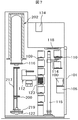
次に、図6、図7を参照して、本実施例に係る基板処理装置100を概略的に説明する。図6は、本発明の実施例に係るバッチ式縦型成膜装置を示す斜視図である。図7は、本発明の実施例に係るバッチ式縦型成膜装置の垂直断面図である。
図6に示すように、基板処理装置100の筐体101内部の前面側には、カセットステージ105が設けられている。カセットステージ105は、図示しない外部搬送装置との間で、基板収納容器としてのカセット100の授受を行う。カセットステージ105の後方には、カセット搬送機115が設けられている。カセット搬送機115の後方には、カセット100を保管するためのカセット棚109が設けられる。また、カセットステージ105の上方には、カセット100を保管するための予備カセット棚110が設けられている。予備カセット棚110の上方には、クリーンユニット118が設けられている。クリーンユニット118は、クリーンエアを筐体101の内部を流通させる。
[Outline of substrate processing equipment]
Next, the
As shown in FIG. 6, a
筐体101の後部上方には、処理炉202が設けられている。処理炉202の下方には、ボートエレベータ121が設けられている。ボートエレベータ121は、ウエハ200を搭載したボート217を、処理炉202の内と外の間で昇降させる。ボート217は、ウエハ200を水平姿勢で多段に保持する基板保持具である。ボートエレベータ121には、処理炉202の下端を塞ぐための蓋体としてのシールキャップ219が取り付けられている。シールキャップ219は、ボート217を垂直に支持する。
ボートエレベータ121とカセット棚109との間には、ウエハ200を搬送するウエハ移載機112が設けられている。ボートエレベータ121の横には、処理炉202の下端を気密に閉塞するための炉口シャッタ116が設けられている。炉口シャッタ116は、ボート217が処理炉202の外にあるときに、処理炉202の下端を閉塞することができる。
A
Between the
ウエハ200が装填されたカセット100は、図示しない外部搬送装置からカセットステージ105に搬入される。さらに、カセット100は、カセット搬送機115により、カセットステージ105からカセット棚109または予備カセット棚110に搬送される。カセット棚109には、ウエハ移載機112の搬送対象となるカセット100が収納される移載棚123がある。ボート217に対してウエハ200が移載されるカセット100は、カセット搬送機115により移載棚123に移載される。カセット100が移載棚123に移載されると、ウエハ移載機112により、移載棚123から降下状態のボート217に、ウエハ200を移載する。
The
ボート217に所定枚数のウエハ200が移載されると、ボートエレベータ121により、ボート217が処理炉202内に挿入され、シールキャップ219により、処理炉202が気密に閉塞される。気密に閉塞された処理炉202内では、ウエハ200が加熱されると共に、処理ガスが処理炉202内に供給され、ウエハ200に加熱等の処理がなされる。
ウエハ200の処理が完了すると、上記した動作の逆の手順により、ウエハ200は、ウエハ移載機112により、ボート217から移載棚123のカセット100に移載され、カセット100は、カセット搬送機115により、移載棚123からカセットステージ105に移載され、図示しない外部搬送装置により、筐体101の外部に搬出される。
ボート217が降下状態において、炉口シャッタ116は、処理炉202の下端を気密に閉塞し、外気が処理炉202内に巻き込まれるのを防止している。
When a predetermined number of
When the processing of the
When the
なお、本発明は、前記実施例に限定されるものではなく、その要旨を逸脱しない範囲で種々に変更が可能であることはいうまでもない。
例えば、成膜処理は窒化チタン膜を形成する処理に限らず、窒化シリコン膜、酸化シリコン膜、他の酸化膜や窒化膜、さらには、金属膜および半導体膜(例えば、ポリシリコン膜)等の他の薄膜を形成する処理であってもよい。
前記実施例においては、ALD法を実施するバッチ式縦型成膜装置について説明したが、本発明は、枚葉装置にも適用することができる。
前記実施例では、ウエハに処理が施される場合について説明したが、処理対象はホトマスクやプリント配線基板、液晶パネル、コンパクトディスクおよび磁気ディスク等であってもよい。
In addition, this invention is not limited to the said Example, It cannot be overemphasized that it can change variously in the range which does not deviate from the summary.
For example, the film forming process is not limited to a process for forming a titanium nitride film, but a silicon nitride film, a silicon oxide film, another oxide film or a nitride film, a metal film, a semiconductor film (for example, a polysilicon film), etc. The process which forms another thin film may be sufficient.
In the above embodiment, the batch type vertical film forming apparatus for carrying out the ALD method has been described, but the present invention can also be applied to a single wafer apparatus.
In the above embodiment, the case where the wafer is processed has been described. However, the processing target may be a photomask, a printed wiring board, a liquid crystal panel, a compact disk, a magnetic disk, or the like.
以上の、本明細書の記載に基づき、次の発明を把握することができる。すなわち、第1の発明は、
基板を収容した基板処理室内に、第1の元素を含む原料ガスを供給して、前記基板上に前記第1の元素を含む膜を形成する第1の工程と、
前記基板処理室内に不活性ガスを瞬時に供給して、前記基板処理室内に残留する前記原料ガスを除去する第2の工程と、
を備えることを特徴とする半導体装置の製造方法。
このように半導体装置の製造方法を構成すると、基板表面等に吸着した余分な原料分子を、短時間で除去することができる。
Based on the above description, the following invention can be grasped. That is, the first invention is
A first step of forming a film containing the first element on the substrate by supplying a source gas containing the first element into a substrate processing chamber containing the substrate;
A second step of instantaneously supplying an inert gas into the substrate processing chamber to remove the source gas remaining in the substrate processing chamber;
A method for manufacturing a semiconductor device, comprising:
By configuring the semiconductor device manufacturing method in this way, it is possible to remove excess raw material molecules adsorbed on the substrate surface or the like in a short time.
第2の発明は、前記第1の発明における半導体装置の製造方法であって、さらに、
前記基板処理室内に、第2の元素を含む改質ガスを供給して、前記基板上に前記第1の工程により形成された第1の元素を含む膜を、前記第1の元素と第2の元素を含む膜に改質する第3の工程と、
前記基板処理室内に不活性ガスを瞬時に供給して、前記基板処理室内に残留する前記改質ガスを除去する第4の工程と、
を備えることを特徴とする半導体装置の製造方法。
このように半導体装置の製造方法を構成すると、第1の工程と第3の工程において基板表面等に吸着した余分な原料分子を、短時間で除去することができる。
A second invention is a method for manufacturing a semiconductor device according to the first invention, further comprising:
A reformed gas containing a second element is supplied into the substrate processing chamber, and a film containing the first element formed on the substrate by the first step is formed with the first element and the second element. A third step of modifying the film to contain the element of
A fourth step of instantaneously supplying an inert gas into the substrate processing chamber to remove the reformed gas remaining in the substrate processing chamber;
A method for manufacturing a semiconductor device, comprising:
When the semiconductor device manufacturing method is configured in this manner, excess source molecules adsorbed on the substrate surface or the like in the first step and the third step can be removed in a short time.
第3の発明は、前記第2の発明における半導体装置の製造方法であって、
前記原料ガスは、常温常圧において液体であり、
前記第1の工程では、前記基板処理室内の雰囲気を排気しつつ、前記原料ガスを前記基板処理室内に供給し、
前記第3の工程では、前記基板処理室内の雰囲気を排気しつつ、前記改質ガスを前記基板処理室内に供給することを特徴とする。
このように半導体装置の製造方法を構成すると、第1の工程や第3の工程において、基板表面等への原料ガスや改質ガスの吸着を抑制できるので、第2の工程や第4の工程において、基板表面等に吸着した余分な原料分子を、短時間で除去することができる。
A third invention is a method of manufacturing a semiconductor device according to the second invention,
The source gas is liquid at normal temperature and pressure,
In the first step, while exhausting the atmosphere in the substrate processing chamber, the source gas is supplied into the substrate processing chamber,
In the third step, the modified gas is supplied into the substrate processing chamber while exhausting the atmosphere in the substrate processing chamber.
When the semiconductor device manufacturing method is configured as described above, the adsorption of the raw material gas or the reformed gas to the substrate surface or the like can be suppressed in the first step or the third step, so that the second step or the fourth step. In FIG. 2, excess source molecules adsorbed on the substrate surface or the like can be removed in a short time.
第4の発明は、前記第2の発明、又は前記第3の発明における半導体装置の製造方法であって、
前記第2の工程及び前記第4の工程において、前記基板処理室内に不活性ガスを供給した後の前記基板処理室内の圧力上昇値が、約10〜200Paであることを特徴とする。
このように半導体装置の製造方法を構成すると、基板表面等に吸着した余分な原料分子を、効果的に、短時間で除去することができる。
A fourth invention is a method of manufacturing a semiconductor device according to the second invention or the third invention,
In the second step and the fourth step, a pressure increase value in the substrate processing chamber after supplying an inert gas into the substrate processing chamber is about 10 to 200 Pa.
By configuring the semiconductor device manufacturing method in this way, it is possible to effectively remove excess source molecules adsorbed on the substrate surface or the like in a short time.
第5の発明は、前記第2の発明ないし前記第4の発明における半導体装置の製造方法であって、
さらに、前記基板処理室に接続されたガス溜め部に不活性ガスを充填する不活性ガス充填工程を備え、
前記第2の工程及び前記第4の工程の前に、前記不活性ガス充填工程を行い、
前記第2の工程及び前記第4の工程では、前記不活性ガス充填工程により前記ガス溜め部に充填された不活性ガスを、前記基板処理室内に供給することを特徴とする。
このように半導体装置の製造方法を構成すると、基板表面等に吸着した余分な原料分子を、短時間で除去することが容易となる。
A fifth invention is a method of manufacturing a semiconductor device according to the second invention to the fourth invention,
In addition, an inert gas filling step of filling an inert gas into a gas reservoir connected to the substrate processing chamber,
Before the second step and the fourth step, perform the inert gas filling step,
In the second step and the fourth step, the inert gas filled in the gas reservoir in the inert gas filling step is supplied into the substrate processing chamber.
By configuring the semiconductor device manufacturing method in this way, it becomes easy to remove excess source molecules adsorbed on the substrate surface or the like in a short time.
第6の発明は、前記第5の発明における半導体装置の製造方法であって、
前記不活性ガス充填工程は、前記第1の工程又は前記第3の工程と、時間的に重なるよう並行して行われることを特徴とする。
このように半導体装置の製造方法を構成すると、生産性を落とすことなく、基板表面等に吸着した余分な原料分子を、短時間で除去することができる。
A sixth invention is a method of manufacturing a semiconductor device according to the fifth invention,
The inert gas filling step is performed in parallel with the first step or the third step so as to overlap in time.
By configuring the semiconductor device manufacturing method in this manner, it is possible to remove excess source molecules adsorbed on the substrate surface or the like in a short time without reducing productivity.
第7の発明は、前記第5の発明又は前記第6の発明における半導体装置の製造方法であって、
前記不活性ガス充填工程においては、前記ガス溜め部の圧力が所定の圧力となるまで、前記ガス溜め部に不活性ガスを充填可能であることを特徴とする。
このように半導体装置の製造方法を構成すると、ガス溜め部の容積を一定としたまま、容積の異なる種々の基板処理室に対応することができる。あるいは、ガス溜め部の容積を一定としたまま、前記基板処理室内に不活性ガスを供給した直後の前記基板処理室内の最適な圧力上昇値が異なる種々の成膜プロセスに対応することができる。
A seventh invention is a method of manufacturing a semiconductor device according to the fifth invention or the sixth invention,
In the inert gas filling step, the gas reservoir can be filled with an inert gas until the pressure of the gas reservoir reaches a predetermined pressure.
By configuring the semiconductor device manufacturing method in this way, it is possible to cope with various substrate processing chambers having different volumes while keeping the volume of the gas reservoir portion constant. Alternatively, it is possible to cope with various film forming processes in which the optimum pressure increase value in the substrate processing chamber immediately after the inert gas is supplied into the substrate processing chamber while the volume of the gas reservoir is constant.
第8の発明は、前記第2の発明ないし前記第7の発明における半導体装置の製造方法であって、
さらに、前記基板処理室内の雰囲気を排気する排気工程を備え、
前記第1の工程、前記第2の工程、前記排気工程、前記第3の工程、前記第4の工程、前記排気工程の順に処理を行うことを特徴とする。
このように半導体装置の製造方法を構成すると、基板表面から脱離した原料分子を、確実に除去することができる。
An eighth invention is a method of manufacturing a semiconductor device according to the second invention to the seventh invention,
And an exhaust process for exhausting the atmosphere in the substrate processing chamber.
Processing is performed in the order of the first step, the second step, the exhaust step, the third step, the fourth step, and the exhaust step.
When the semiconductor device manufacturing method is configured in this manner, source molecules desorbed from the substrate surface can be reliably removed.
第9の発明は、前記第2の発明ないし前記第4の発明における半導体装置の製造方法であって、
さらに、前記基板処理室に接続された不活性ガス供給管に不活性ガスを充填する不活性ガス充填工程を備え、
前記第2の工程及び前記第4の工程の前に、前記不活性ガス充填工程を行い、
前記第2の工程及び前記第4の工程では、前記不活性ガス充填工程により前記不活性ガス供給管に充填された不活性ガスを、前記基板処理室内に供給することを特徴とする。
このように半導体装置の製造方法を構成すると、基板表面等に吸着した余分な原料分子を、短時間で除去することが容易となる。
A ninth invention is a method of manufacturing a semiconductor device according to the second invention or the fourth invention,
And an inert gas filling step of filling an inert gas supply pipe connected to the substrate processing chamber with an inert gas,
Before the second step and the fourth step, perform the inert gas filling step,
In the second step and the fourth step, the inert gas filled in the inert gas supply pipe in the inert gas filling step is supplied into the substrate processing chamber.
By configuring the semiconductor device manufacturing method in this way, it becomes easy to remove excess source molecules adsorbed on the substrate surface or the like in a short time.
第10の発明は、
基板を収容する基板処理室と、
前記基板処理室内に原料ガスを供給する原料ガス供給部と、
前記基板処理室内に不活性ガスを供給する不活性ガス供給部と、
前記基板処理室内の雰囲気を排気する排気部と、
前記原料ガス供給部、前記不活性ガス供給部、前記排気部を制御する制御部とを備え、
前記制御部は、前記基板処理室内に原料ガスを供給した後、前記基板処理室内に不活性ガスを供給し、前記基板処理室内に不活性ガスを供給するときは、不活性ガスを瞬時に供給するよう制御することを特徴とする基板処理装置。
このように基板処理装置を構成すると、基板表面等に吸着した余分な原料分子を、短時間で除去することができる。
The tenth invention is
A substrate processing chamber for storing the substrate;
A source gas supply unit for supplying source gas into the substrate processing chamber;
An inert gas supply unit for supplying an inert gas into the substrate processing chamber;
An exhaust section for exhausting the atmosphere in the substrate processing chamber;
A control unit for controlling the source gas supply unit, the inert gas supply unit, and the exhaust unit;
The control unit supplies the inert gas into the substrate processing chamber after supplying the source gas into the substrate processing chamber, and instantaneously supplies the inert gas when supplying the inert gas into the substrate processing chamber. A substrate processing apparatus, characterized in that control is performed.
When the substrate processing apparatus is configured in this manner, excess source molecules adsorbed on the substrate surface or the like can be removed in a short time.
第11の発明は、前記第10の発明における基板処理装置であって、さらに、
前記基板処理室内に改質ガスを供給する改質ガス供給部を備え、
前記制御部は、前記基板処理室内に原料ガスを供給した後、前記基板処理室内に不活性ガスを供給し、次に、前記基板処理室内に改質ガスを供給した後、前記基板処理室内に不活性ガスを供給するよう制御するものであり、前記基板処理室内に不活性ガスを供給するときは、不活性ガスを瞬時に供給するよう制御することを特徴とする基板処理装置。
このように基板処理装置を構成すると、原料ガス供給工程と改質ガス供給工程において基板表面等に吸着した余分な原料分子を、短時間で除去することができる。
An eleventh invention is the substrate processing apparatus according to the tenth invention, further comprising:
A reformed gas supply unit for supplying a reformed gas into the substrate processing chamber;
The controller supplies a source gas into the substrate processing chamber, then supplies an inert gas into the substrate processing chamber, and then supplies a reformed gas into the substrate processing chamber, and then into the substrate processing chamber. A substrate processing apparatus for controlling to supply an inert gas, wherein when the inert gas is supplied into the substrate processing chamber, the inert gas is controlled to be supplied instantaneously.
When the substrate processing apparatus is configured in this manner, excess source molecules adsorbed on the substrate surface or the like in the source gas supply step and the reformed gas supply step can be removed in a short time.
第12の発明は、前記第10の発明又は前記第11の発明における基板処理装置であって、
前記不活性ガス供給部は、前記基板処理室と接続された不活性ガス供給管と、該不活性ガス供給管を開閉する第1の不活性ガス開閉バルブと、該第1の不活性ガス開閉バルブよりも上流に設けられたガス溜め部を備え、
前記制御部は、前記第1の不活性ガス開閉バルブを閉じた状態で、不活性ガスを前記不活性ガス供給管に供給してガス溜め部に溜めた後、前記第1の不活性ガス開閉バルブを開けて、前記ガス溜め部に溜めた不活性ガスを、前記基板処理室に供給するよう制御することを特徴とする。
このように基板処理装置を構成すると、基板表面等に吸着した余分な原料分子を、短時間で除去することができる。
A twelfth invention is the substrate processing apparatus according to the tenth invention or the eleventh invention,
The inert gas supply unit includes an inert gas supply pipe connected to the substrate processing chamber, a first inert gas opening / closing valve for opening / closing the inert gas supply pipe, and the first inert gas opening / closing. It has a gas reservoir provided upstream from the valve,
The control unit supplies the inert gas to the inert gas supply pipe and stores the inert gas in the gas reservoir with the first inert gas on / off valve closed, and then opens and closes the first inert gas on / off. The valve is opened to control so that the inert gas stored in the gas reservoir is supplied to the substrate processing chamber.
When the substrate processing apparatus is configured in this manner, excess source molecules adsorbed on the substrate surface or the like can be removed in a short time.
第13の発明は、前記第12の発明における基板処理装置であって、
前記不活性ガス供給部は、前記ガス溜め部よりも上流に設けられた第2の不活性ガス開閉バルブを備え、
前記制御部は、前記第1の不活性ガス開閉バルブを閉じ、前記第2の不活性ガス開閉バルブを開けた状態で、不活性ガスを前記不活性ガス供給管に供給してガス溜め部に溜めた後、前記第1の不活性ガス開閉バルブを開け、前記第2の不活性ガス開閉バルブを閉じた状態で、前記ガス溜め部に溜めた不活性ガスを、前記基板処理室に供給するよう制御することを特徴とする。
このように基板処理装置を構成すると、基板処理室内の圧力上昇値を制御することが容易となる。
A thirteenth invention is the substrate processing apparatus according to the twelfth invention,
The inert gas supply unit includes a second inert gas opening / closing valve provided upstream of the gas reservoir,
The controller supplies the inert gas to the inert gas supply pipe and closes the gas reservoir with the first inert gas on / off valve closed and the second inert gas on / off valve opened. After the reservoir, the first inert gas opening / closing valve is opened, and the inert gas stored in the gas reservoir is supplied to the substrate processing chamber with the second inert gas opening / closing valve closed. It is characterized by controlling as follows.
By configuring the substrate processing apparatus in this way, it becomes easy to control the pressure increase value in the substrate processing chamber.
第14の発明は、前記第12の発明ないし前記第13の発明における基板処理装置であって、
前記ガス溜め部の内径は、前記不活性ガス供給管の内径よりも大きいものであることを特徴とする。
このように基板処理装置を構成すると、ガス溜め部に溜めた不活性ガスを、短時間で、基板処理室へ供給することが容易となる。
A fourteenth invention is a substrate processing apparatus according to the twelfth invention to the thirteenth invention,
An inner diameter of the gas reservoir is larger than an inner diameter of the inert gas supply pipe.
When the substrate processing apparatus is configured in this way, it becomes easy to supply the inert gas stored in the gas storage section to the substrate processing chamber in a short time.
第15の発明は、前記第12の発明ないし前記第14の発明における基板処理装置であって、
前記基板処理室の容積と、前記ガス溜め部の容積との容積比は、約200〜2000であることを特徴とする。
このように基板処理装置を構成すると、基板表面等に吸着した余分な原料分子を、効果的に、短時間で除去することができる。
A fifteenth aspect of the invention is a substrate processing apparatus according to the twelfth aspect of the invention to the fourteenth aspect of the invention,
The volume ratio between the volume of the substrate processing chamber and the volume of the gas reservoir is about 200 to 2000.
When the substrate processing apparatus is configured in this manner, excess source molecules adsorbed on the substrate surface or the like can be effectively removed in a short time.
第16の発明は、前記第10の発明又は前記第11の発明における基板処理装置であって、
前記不活性ガス供給部は、前記基板処理室と接続された不活性ガス供給管と、該不活性ガス供給管を開閉する第1の不活性ガス開閉バルブとを備え、
前記制御部は、前記第1の不活性ガス開閉バルブを閉じた状態で、不活性ガスを前記不活性ガス供給管に充填した後、前記第1の不活性ガス開閉バルブを開けて、前記不活性ガス供給管に充填した不活性ガスを、前記基板処理室に供給するよう制御することを特徴とする。
このように基板処理装置を構成すると、基板表面等に吸着した余分な原料分子を、短時間で除去することができる。
A sixteenth invention is the substrate processing apparatus of the tenth invention or the eleventh invention,
The inert gas supply unit includes an inert gas supply pipe connected to the substrate processing chamber, and a first inert gas opening / closing valve that opens and closes the inert gas supply pipe,
The control unit fills the inert gas supply pipe with the inert gas while the first inert gas opening / closing valve is closed, and then opens the first inert gas opening / closing valve to Control is performed so that an inert gas filled in an active gas supply pipe is supplied to the substrate processing chamber.
When the substrate processing apparatus is configured in this manner, excess source molecules adsorbed on the substrate surface or the like can be removed in a short time.
100…基板処理装置、200…ウエハ、201…基板処理室、202…処理炉、203…反応管、207…ヒータ、208…断熱部材、217…ボート、218…石英キャップ、219…シールキャップ、220…Oリング、224…プラズマ生成領域、231…ガス排気管、232a…第2のガス供給管、232b…第1のガス供給管、232c…クリーニングガス供給管、232e…ガス供給管、232f…ガス供給管、233…ノズル、237…バッファ室、240a…第2の処理ガス供給源、240b…第1の処理ガス供給源、240c…クリーニングガス供給源、240e…不活性ガス供給源、240f…不活性ガス供給源、241a…マスフローコントローラ、241b…マスフローコントローラ、241c…マスフローコントローラ、241e…マスフローコントローラ、241f…マスフローコントローラ、243a…開閉バルブ、243b…開閉バルブ、243c…開閉バルブ、243d…開閉バルブ、243e…開閉バルブ、243f…開閉バルブ、243g…APCバルブ、244e…圧力センサ、244f…圧力センサ、244g…圧力センサ、245e…ガス溜め部、245f…ガス溜め部、246…真空ポンプ、247…ヒータ、248a…ガス供給孔、248b…ガス供給孔、248c…ガス供給孔、249…ガス供給室、267…ボート回転機構、269…棒状電極、270…棒状電極、272…整合器、273…高周波電源、275…電極保護管、321…コントローラ。
DESCRIPTION OF
Claims (3)
前記基板処理室内に不活性ガスを供給して、前記基板処理室内に残留する前記原料ガスを除去する第2の工程と、
前記基板処理室内に、前記所定の元素と反応する改質ガスを供給して、前記基板上に前記第1の工程により形成された所定の元素を含む膜を改質する第3の工程と、
前記基板処理室内に不活性ガスを供給して、前記基板処理室内に残留する前記改質ガスを除去する第4の工程と、
前記基板処理室に接続されたガス溜め部に不活性ガスを充填する不活性ガス充填工程とを備え、
前記第2の工程及び前記第4の工程の前に、前記不活性ガス充填工程を行い、
前記第2の工程及び前記第4の工程では、前記不活性ガス充填工程により前記ガス溜め部に充填された不活性ガスを、前記基板処理室内に供給し、該不活性ガスを供給したときに、該不活性ガスを供給する前と比較して前記基板処理室内の圧力を10〜200Pa上昇することを特徴とする半導体装置の製造方法。 A first step of forming a film containing the predetermined element on the substrate by supplying a source gas containing the predetermined element into a substrate processing chamber containing the substrate;
A second step of supplying an inert gas into the substrate processing chamber to remove the source gas remaining in the substrate processing chamber;
A third step of reforming a film containing the predetermined element formed on the substrate by the first step by supplying a reforming gas that reacts with the predetermined element into the substrate processing chamber;
A fourth step of supplying an inert gas into the substrate processing chamber to remove the reformed gas remaining in the substrate processing chamber;
An inert gas filling step of filling an inert gas into a gas reservoir connected to the substrate processing chamber,
Before the second step and the fourth step, perform the inert gas filling step,
In the second step and the fourth step, when the inert gas filled in the gas reservoir in the inert gas filling step is supplied into the substrate processing chamber, and the inert gas is supplied. A method of manufacturing a semiconductor device, wherein the pressure in the substrate processing chamber is increased by 10 to 200 Pa as compared to before supplying the inert gas.
前記基板処理室内に不活性ガスを供給して、前記基板処理室内に残留する前記原料ガスを除去する第2の工程と、
前記基板処理室内に、前記所定の元素と反応する改質ガスを供給して、前記基板上に前記第1の工程により形成された所定の元素を含む膜を改質する第3の工程と、
前記基板処理室内に不活性ガスを供給して、前記基板処理室内に残留する前記改質ガスを除去する第4の工程と、
前記基板処理室に接続された不活性ガス供給管に不活性ガスを充填する不活性ガス充填工程とを備え、
前記第2の工程及び前記第4の工程の前に、前記不活性ガス充填工程を行い、
前記第2の工程及び前記第4の工程では、前記不活性ガス充填工程により前記不活性ガス供給管に充填された不活性ガスを、前記基板処理室内に供給し、該不活性ガスを供給したときに、該不活性ガスを供給する前と比較して前記基板処理室内の圧力を10〜200Pa上昇することを特徴とする半導体装置の製造方法。 A first step of forming a film containing the predetermined element on the substrate by supplying a source gas containing the predetermined element into a substrate processing chamber containing the substrate;
A second step of supplying an inert gas into the substrate processing chamber to remove the source gas remaining in the substrate processing chamber;
A third step of reforming a film containing the predetermined element formed on the substrate by the first step by supplying a reforming gas that reacts with the predetermined element into the substrate processing chamber;
A fourth step of supplying an inert gas into the substrate processing chamber to remove the reformed gas remaining in the substrate processing chamber;
An inert gas filling step of filling an inert gas supply pipe connected to the substrate processing chamber with an inert gas;
Before the second step and the fourth step, perform the inert gas filling step,
In the second step and the fourth step, the inert gas filled in the inert gas supply pipe in the inert gas filling step is supplied into the substrate processing chamber, and the inert gas is supplied. In some cases, the method of manufacturing a semiconductor device is characterized in that the pressure in the substrate processing chamber is increased by 10 to 200 Pa as compared to before supplying the inert gas.
前記基板処理室内に原料ガスを供給する原料ガス供給部と、
前記基板処理室内に改質ガスを供給する改質ガス供給部と、
前記基板処理室内に不活性ガスを供給する不活性ガス供給部と、
前記基板処理室内の雰囲気を排気する排気部と、
前記原料ガス供給部、前記改質ガス供給部、前記不活性ガス供給部、前記排気部を制御する制御部とを備えた基板処理装置であって、
前記不活性ガス供給部は、前記基板処理室と接続された不活性ガス供給管と、該不活性ガス供給管を開閉する第1の不活性ガス開閉バルブと、該第1の不活性ガス開閉バルブよりも上流に設けられたガス溜め部を備え、
前記制御部は、前記基板処理室内に原料ガスを供給する第1の工程を行った後、前記基板処理室内に不活性ガスを供給する第2の工程を行い、次に、前記基板処理室内に改質ガスを供給する第3の工程を行った後、前記基板処理室内に不活性ガスを供給する第4の工程を行うよう制御するものであり、前記第2及び第4の工程において前記基板処理室内に不活性ガスを供給するときは、前記第1の不活性ガス開閉バルブを閉じた状態で、不活性ガスを前記不活性ガス供給管に供給してガス溜め部に溜めた後、前記第1の不活性ガス開閉バルブを開けて、前記ガス溜め部に溜めた不活性ガスを、前記基板処理室内に供給するよう制御し、
前記第2及び第4の工程において不活性ガスを供給したときに、該不活性ガスを供給する前と比較して前記基板処理室内の圧力を10〜200Pa上昇することを特徴とする基板処理装置。 A substrate processing chamber for storing the substrate;
A source gas supply unit for supplying source gas into the substrate processing chamber;
A reformed gas supply unit for supplying a reformed gas into the substrate processing chamber;
An inert gas supply unit for supplying an inert gas into the substrate processing chamber;
An exhaust section for exhausting the atmosphere in the substrate processing chamber;
A substrate processing apparatus comprising: the source gas supply unit; the reformed gas supply unit; the inert gas supply unit; and a control unit that controls the exhaust unit,
The inert gas supply unit includes an inert gas supply pipe connected to the substrate processing chamber, a first inert gas opening / closing valve for opening / closing the inert gas supply pipe, and the first inert gas opening / closing. It has a gas reservoir provided upstream from the valve,
The controller performs a first step of supplying a source gas into the substrate processing chamber, then performs a second step of supplying an inert gas into the substrate processing chamber, and then into the substrate processing chamber. After performing the third step of supplying the reformed gas, control is performed so as to perform a fourth step of supplying an inert gas into the substrate processing chamber. In the second and fourth steps, the substrate is controlled. When supplying the inert gas into the processing chamber, the inert gas is supplied to the inert gas supply pipe and stored in the gas reservoir with the first inert gas opening / closing valve closed, Opening the first inert gas on-off valve and controlling the inert gas accumulated in the gas reservoir to be supplied into the substrate processing chamber;
When the inert gas is supplied in the second and fourth steps, the pressure in the substrate processing chamber is increased by 10 to 200 Pa as compared to before the inert gas is supplied. apparatus.
Priority Applications (6)
| Application Number | Priority Date | Filing Date | Title |
|---|---|---|---|
| JP2009210590A JP5520552B2 (en) | 2009-09-11 | 2009-09-11 | Semiconductor device manufacturing method and substrate processing apparatus |
| KR1020100028133A KR101195410B1 (en) | 2009-09-11 | 2010-03-29 | Semiconductor device manufacturing method and substrate processing apparatus |
| TW099109584A TWI428986B (en) | 2009-09-11 | 2010-03-30 | Semiconductor device manufacturing method and substrate processing device |
| US12/750,105 US8093158B2 (en) | 2009-09-11 | 2010-03-30 | Semiconductor device manufacturing method and substrate processing apparatus |
| CN2010101666685A CN102024688B (en) | 2009-09-11 | 2010-04-27 | Semiconductor device manufacturing method and substrate processing device |
| US13/311,760 US8590484B2 (en) | 2009-09-11 | 2011-12-06 | Semiconductor device manufacturing method and substrate processing apparatus |
Applications Claiming Priority (1)
| Application Number | Priority Date | Filing Date | Title |
|---|---|---|---|
| JP2009210590A JP5520552B2 (en) | 2009-09-11 | 2009-09-11 | Semiconductor device manufacturing method and substrate processing apparatus |
Publications (2)
| Publication Number | Publication Date |
|---|---|
| JP2011058067A JP2011058067A (en) | 2011-03-24 |
| JP5520552B2 true JP5520552B2 (en) | 2014-06-11 |
Family
ID=43730996
Family Applications (1)
| Application Number | Title | Priority Date | Filing Date |
|---|---|---|---|
| JP2009210590A Active JP5520552B2 (en) | 2009-09-11 | 2009-09-11 | Semiconductor device manufacturing method and substrate processing apparatus |
Country Status (5)
| Country | Link |
|---|---|
| US (2) | US8093158B2 (en) |
| JP (1) | JP5520552B2 (en) |
| KR (1) | KR101195410B1 (en) |
| CN (1) | CN102024688B (en) |
| TW (1) | TWI428986B (en) |
Cited By (1)
| Publication number | Priority date | Publication date | Assignee | Title |
|---|---|---|---|---|
| US11840760B2 (en) | 2018-04-02 | 2023-12-12 | Samsung Electronics Co., Ltd. | Layer deposition method and layer deposition apparatus |
Families Citing this family (28)
| Publication number | Priority date | Publication date | Assignee | Title |
|---|---|---|---|---|
| JP5423205B2 (en) * | 2008-08-29 | 2014-02-19 | 東京エレクトロン株式会社 | Deposition equipment |
| JP5520552B2 (en) | 2009-09-11 | 2014-06-11 | 株式会社日立国際電気 | Semiconductor device manufacturing method and substrate processing apparatus |
| TWI458843B (en) * | 2011-10-06 | 2014-11-01 | Ind Tech Res Inst | Evaporation apparatus and method of forminf organic film |
| KR101308111B1 (en) * | 2011-11-17 | 2013-09-26 | 주식회사 유진테크 | Apparatus and method for processing substrate including exhaust ports |
| JP6016542B2 (en) * | 2012-09-13 | 2016-10-26 | 株式会社日立国際電気 | Reaction tube, substrate processing apparatus, and semiconductor device manufacturing method |
| JP6222833B2 (en) * | 2013-01-30 | 2017-11-01 | 株式会社日立国際電気 | Substrate processing apparatus, semiconductor device manufacturing method, and program |
| JP6107327B2 (en) * | 2013-03-29 | 2017-04-05 | 東京エレクトロン株式会社 | Film forming apparatus, gas supply apparatus, and film forming method |
| JP6336719B2 (en) * | 2013-07-16 | 2018-06-06 | 株式会社ディスコ | Plasma etching equipment |
| JP5801374B2 (en) * | 2013-12-27 | 2015-10-28 | 株式会社日立国際電気 | Semiconductor device manufacturing method, program, and substrate processing apparatus |
| JP2015185837A (en) * | 2014-03-26 | 2015-10-22 | 東京エレクトロン株式会社 | Deposition device |
| JP6415215B2 (en) * | 2014-09-26 | 2018-10-31 | 株式会社Kokusai Electric | Substrate processing apparatus, semiconductor device manufacturing method, and program |
| US10100407B2 (en) * | 2014-12-19 | 2018-10-16 | Lam Research Corporation | Hardware and process for film uniformity improvement |
| JP2016134569A (en) * | 2015-01-21 | 2016-07-25 | 株式会社東芝 | Semiconductor manufacturing equipment |
| JP6023854B1 (en) * | 2015-06-09 | 2016-11-09 | 株式会社日立国際電気 | Semiconductor device manufacturing method, substrate processing apparatus, and program |
| WO2017037937A1 (en) * | 2015-09-04 | 2017-03-09 | 株式会社日立国際電気 | Reaction tube, substrate processing device and semiconductor device manufacturing method |
| JP2017183392A (en) * | 2016-03-29 | 2017-10-05 | 株式会社日立国際電気 | Substrate processing apparatus, semiconductor device manufacturing method, and recording medium |
| JP6616258B2 (en) | 2016-07-26 | 2019-12-04 | 株式会社Kokusai Electric | Substrate processing apparatus, lid cover, and semiconductor device manufacturing method |
| JP6900640B2 (en) * | 2016-08-03 | 2021-07-07 | 東京エレクトロン株式会社 | Gas supply device and gas supply method |
| JP6851173B2 (en) * | 2016-10-21 | 2021-03-31 | 東京エレクトロン株式会社 | Film formation equipment and film formation method |
| JP6737139B2 (en) * | 2016-11-14 | 2020-08-05 | 東京エレクトロン株式会社 | Gas injector and vertical heat treatment equipment |
| KR102147174B1 (en) * | 2016-11-18 | 2020-08-28 | 가부시키가이샤 코쿠사이 엘렉트릭 | Substrate processing apparatus, reaction tube structure and method of manufacturing semiconductor device |
| JP6773880B2 (en) | 2017-02-23 | 2020-10-21 | 株式会社Kokusai Electric | Substrate processing equipment, semiconductor equipment manufacturing methods, computer programs and processing containers |
| JP6586433B2 (en) * | 2017-03-30 | 2019-10-02 | 株式会社Kokusai Electric | Substrate processing method, substrate processing apparatus, program |
| JP6816260B2 (en) * | 2017-03-31 | 2021-01-20 | 株式会社Fuji | Plasma generator |
| CN109321897B (en) * | 2017-07-31 | 2022-01-07 | 北京北方华创微电子装备有限公司 | Atomic layer deposition system and method |
| US10903103B2 (en) * | 2018-01-22 | 2021-01-26 | Nanya Technology Corporation | Front opening unified pod |
| JP6902060B2 (en) | 2019-02-13 | 2021-07-14 | 株式会社Kokusai Electric | Substrate processing equipment, semiconductor equipment manufacturing methods, and programs |
| JP7203070B2 (en) * | 2020-09-23 | 2023-01-12 | 株式会社Kokusai Electric | Substrate processing apparatus, substrate processing method, and semiconductor device manufacturing method |
Family Cites Families (51)
| Publication number | Priority date | Publication date | Assignee | Title |
|---|---|---|---|---|
| JPS58128728A (en) * | 1982-01-28 | 1983-08-01 | Toshiba Mach Co Ltd | Semiconductor vapor growth apparatus |
| EP0518524B1 (en) * | 1991-05-30 | 1996-09-04 | Hitachi, Ltd. | Valve and semiconductor fabricating equipment using the same |
| KR950001953A (en) * | 1993-06-30 | 1995-01-04 | 이노우에 아키라 | Wafer heat treatment method |
| US5484484A (en) * | 1993-07-03 | 1996-01-16 | Tokyo Electron Kabushiki | Thermal processing method and apparatus therefor |
| US5777300A (en) * | 1993-11-19 | 1998-07-07 | Tokyo Electron Kabushiki Kaisha | Processing furnace for oxidizing objects |
| KR100306527B1 (en) * | 1994-06-15 | 2002-06-26 | 구사마 사부로 | Manufacturing method of thin film semiconductor device, thin film semiconductor device |
| DE19605440A1 (en) * | 1996-02-14 | 1997-08-21 | Messer Griesheim Gmbh | Automatic emptying method for material in container e.g. gas cylinder |
| US6797323B1 (en) * | 1996-11-29 | 2004-09-28 | Sony Corporation | Method of forming silicon oxide layer |
| TW462093B (en) * | 1997-03-05 | 2001-11-01 | Hitachi Ltd | Method for manufacturing semiconductor integrated circuit device having a thin insulative film |
| US6197123B1 (en) * | 1997-12-18 | 2001-03-06 | Texas Instruments Incorporated | Method for cleaning a process chamber used for manufacturing substrates during nonproduction intervals |
| JP2002536549A (en) | 1999-02-12 | 2002-10-29 | ゲレスト インコーポレイテッド | Chemical vapor deposition of tungsten nitride |
| US6305314B1 (en) * | 1999-03-11 | 2001-10-23 | Genvs, Inc. | Apparatus and concept for minimizing parasitic chemical vapor deposition during atomic layer deposition |
| US6581623B1 (en) * | 1999-07-16 | 2003-06-24 | Advanced Technology Materials, Inc. | Auto-switching gas delivery system utilizing sub-atmospheric pressure gas supply vessels |
| TW460942B (en) * | 1999-08-31 | 2001-10-21 | Mitsubishi Material Silicon | CVD device, purging method, method for determining maintenance time for a semiconductor making device, moisture content monitoring device, and semiconductor making device with such moisture content monitoring device |
| US6261408B1 (en) * | 2000-02-16 | 2001-07-17 | Applied Materials, Inc. | Method and apparatus for semiconductor processing chamber pressure control |
| US6884295B2 (en) * | 2000-05-29 | 2005-04-26 | Tokyo Electron Limited | Method of forming oxynitride film or the like and system for carrying out the same |
| US6585823B1 (en) * | 2000-07-07 | 2003-07-01 | Asm International, N.V. | Atomic layer deposition |
| US20020197402A1 (en) * | 2000-12-06 | 2002-12-26 | Chiang Tony P. | System for depositing a film by modulated ion-induced atomic layer deposition (MII-ALD) |
| US20050189074A1 (en) * | 2002-11-08 | 2005-09-01 | Tokyo Electron Limited | Gas processing apparatus and method and computer storage medium storing program for controlling same |
| KR20020074708A (en) | 2001-03-21 | 2002-10-04 | 삼성전자 주식회사 | Method for Increase of Gas Flow |
| US20020144655A1 (en) * | 2001-04-05 | 2002-10-10 | Chiang Tony P. | Gas valve system for a reactor |
| JP3421660B2 (en) * | 2001-05-09 | 2003-06-30 | 東京エレクトロン株式会社 | Heat treatment apparatus and method |
| US6656282B2 (en) * | 2001-10-11 | 2003-12-02 | Moohan Co., Ltd. | Atomic layer deposition apparatus and process using remote plasma |
| US6911391B2 (en) * | 2002-01-26 | 2005-06-28 | Applied Materials, Inc. | Integration of titanium and titanium nitride layers |
| JP3985899B2 (en) * | 2002-03-28 | 2007-10-03 | 株式会社日立国際電気 | Substrate processing equipment |
| US6720027B2 (en) * | 2002-04-08 | 2004-04-13 | Applied Materials, Inc. | Cyclical deposition of a variable content titanium silicon nitride layer |
| JP3947126B2 (en) | 2002-04-11 | 2007-07-18 | 株式会社日立国際電気 | Semiconductor manufacturing equipment |
| US20040247787A1 (en) * | 2002-04-19 | 2004-12-09 | Mackie Neil M. | Effluent pressure control for use in a processing system |
| WO2003089682A1 (en) * | 2002-04-19 | 2003-10-30 | Mattson Technology, Inc. | System for depositing a film onto a substrate using a low vapor pressure gas precursor |
| EP1549787A1 (en) * | 2002-10-03 | 2005-07-06 | Koninklijke Philips Electronics N.V. | Method and apparatus for forming epitaxial layers |
| KR100520902B1 (en) | 2002-11-20 | 2005-10-12 | 주식회사 아이피에스 | Method for depositing thin film on wafer using Aluminum compound |
| JP3866655B2 (en) * | 2002-12-26 | 2007-01-10 | 励起 渡辺 | Processing apparatus and processing method |
| JP2004288916A (en) * | 2003-03-24 | 2004-10-14 | Renesas Technology Corp | Cvd apparatus |
| KR101046523B1 (en) * | 2003-04-22 | 2011-07-04 | 도쿄엘렉트론가부시키가이샤 | Removal method of chemical oxide |
| WO2004095555A1 (en) * | 2003-04-22 | 2004-11-04 | Tokyo Electron Limited | Method for cleaning heat treatment apparatus |
| US7437944B2 (en) * | 2003-12-04 | 2008-10-21 | Applied Materials, Inc. | Method and apparatus for pressure and mix ratio control |
| JP3945519B2 (en) * | 2004-06-21 | 2007-07-18 | 東京エレクトロン株式会社 | Heat treatment apparatus, heat treatment method and storage medium for object to be processed |
| JP2006073997A (en) * | 2004-08-02 | 2006-03-16 | Tokyo Electron Ltd | Film forming method, film forming apparatus, and storage medium |
| JP2006066540A (en) * | 2004-08-25 | 2006-03-09 | Tokyo Electron Ltd | Thin film forming apparatus cleaning method and thin film forming apparatus |
| JP4566787B2 (en) * | 2005-02-28 | 2010-10-20 | 株式会社日立国際電気 | Substrate processing apparatus and semiconductor device manufacturing method |
| JP2006269532A (en) * | 2005-03-22 | 2006-10-05 | Hitachi Kokusai Electric Inc | Manufacturing method of semiconductor device |
| JP4736564B2 (en) * | 2005-06-23 | 2011-07-27 | 東京エレクトロン株式会社 | Mounting structure and processing device of mounting table device |
| JP2007067119A (en) * | 2005-08-30 | 2007-03-15 | Elpida Memory Inc | Semiconductor manufacturing apparatus |
| WO2007114156A1 (en) | 2006-03-30 | 2007-10-11 | Mitsui Engineering & Shipbuilding Co., Ltd. | Atomic layer growing apparatus |
| KR20070106286A (en) | 2006-04-28 | 2007-11-01 | 주식회사 하이닉스반도체 | Method for forming titanium oxide film crystallized in rutile structure and method for manufacturing capacitor using same |
| JP4939864B2 (en) * | 2006-07-25 | 2012-05-30 | 東京エレクトロン株式会社 | Gas supply apparatus, gas supply method, thin film forming apparatus cleaning method, thin film forming method, and thin film forming apparatus |
| JP4990594B2 (en) * | 2006-10-12 | 2012-08-01 | 東京エレクトロン株式会社 | Gas supply apparatus, gas supply method, thin film forming apparatus cleaning method, thin film forming method, and thin film forming apparatus |
| JP4961381B2 (en) * | 2008-04-14 | 2012-06-27 | 株式会社日立国際電気 | Substrate processing apparatus, substrate processing method, and semiconductor device manufacturing method |
| JP4814914B2 (en) * | 2008-07-07 | 2011-11-16 | 株式会社日立国際電気 | Substrate processing apparatus and semiconductor device manufacturing method |
| JP5247528B2 (en) * | 2009-02-23 | 2013-07-24 | 株式会社日立国際電気 | Substrate processing apparatus, semiconductor device manufacturing method, substrate processing method, and gas introducing means |
| JP5520552B2 (en) | 2009-09-11 | 2014-06-11 | 株式会社日立国際電気 | Semiconductor device manufacturing method and substrate processing apparatus |
-
2009
- 2009-09-11 JP JP2009210590A patent/JP5520552B2/en active Active
-
2010
- 2010-03-29 KR KR1020100028133A patent/KR101195410B1/en active Active
- 2010-03-30 US US12/750,105 patent/US8093158B2/en active Active
- 2010-03-30 TW TW099109584A patent/TWI428986B/en active
- 2010-04-27 CN CN2010101666685A patent/CN102024688B/en active Active
-
2011
- 2011-12-06 US US13/311,760 patent/US8590484B2/en active Active
Cited By (1)
| Publication number | Priority date | Publication date | Assignee | Title |
|---|---|---|---|---|
| US11840760B2 (en) | 2018-04-02 | 2023-12-12 | Samsung Electronics Co., Ltd. | Layer deposition method and layer deposition apparatus |
Also Published As
| Publication number | Publication date |
|---|---|
| US20110065283A1 (en) | 2011-03-17 |
| JP2011058067A (en) | 2011-03-24 |
| US20120073500A1 (en) | 2012-03-29 |
| US8590484B2 (en) | 2013-11-26 |
| CN102024688A (en) | 2011-04-20 |
| CN102024688B (en) | 2013-04-10 |
| TW201110232A (en) | 2011-03-16 |
| US8093158B2 (en) | 2012-01-10 |
| KR20110028203A (en) | 2011-03-17 |
| TWI428986B (en) | 2014-03-01 |
| KR101195410B1 (en) | 2012-10-29 |
Similar Documents
| Publication | Publication Date | Title |
|---|---|---|
| JP5520552B2 (en) | Semiconductor device manufacturing method and substrate processing apparatus | |
| JP4734317B2 (en) | Substrate processing method and substrate processing apparatus | |
| JP5137903B2 (en) | Substrate processing apparatus, semiconductor device manufacturing method, and electrode | |
| JP2004281853A (en) | Substrate processing equipment | |
| JP5568212B2 (en) | Substrate processing apparatus, coating method therefor, substrate processing method, and semiconductor device manufacturing method | |
| JP2009263764A (en) | Semiconductor manufacturing apparatus and semiconductor device manufacturing method | |
| JP2012114200A (en) | Substrate processing apparatus | |
| JP4566787B2 (en) | Substrate processing apparatus and semiconductor device manufacturing method | |
| JP2011187536A (en) | Substrate processing device | |
| JP4938805B2 (en) | Substrate processing equipment | |
| JP4434807B2 (en) | Manufacturing method of semiconductor device | |
| JP4267434B2 (en) | Substrate processing equipment | |
| JP2005243737A (en) | Substrate processing equipment | |
| JP4509697B2 (en) | Substrate processing equipment | |
| JP2005167027A (en) | Substrate processing equipment | |
| JP2011159906A (en) | Method of manufacturing semiconductor device | |
| JP2005277264A (en) | Substrate processing apparatus | |
| JP4634155B2 (en) | Substrate processing apparatus and film forming method | |
| JP2006066593A (en) | Substrate processing equipment | |
| JP2009253013A (en) | Substrate processing apparatus | |
| JP2005340281A (en) | Substrate processing equipment | |
| JP2005251775A (en) | Substrate processing equipment | |
| JP2006013204A (en) | Substrate processing device | |
| JP2006190875A (en) | Substrate processing equipment | |
| JP2005191169A (en) | Substrate processing equipment |
Legal Events
| Date | Code | Title | Description |
|---|---|---|---|
| A621 | Written request for application examination |
Free format text: JAPANESE INTERMEDIATE CODE: A621 Effective date: 20120903 |
|
| A977 | Report on retrieval |
Free format text: JAPANESE INTERMEDIATE CODE: A971007 Effective date: 20130725 |
|
| A131 | Notification of reasons for refusal |
Free format text: JAPANESE INTERMEDIATE CODE: A131 Effective date: 20130806 |
|
| A977 | Report on retrieval |
Free format text: JAPANESE INTERMEDIATE CODE: A971007 Effective date: 20130903 |
|
| A521 | Request for written amendment filed |
Free format text: JAPANESE INTERMEDIATE CODE: A523 Effective date: 20131003 |
|
| A02 | Decision of refusal |
Free format text: JAPANESE INTERMEDIATE CODE: A02 Effective date: 20131029 |
|
| A521 | Request for written amendment filed |
Free format text: JAPANESE INTERMEDIATE CODE: A523 Effective date: 20140128 |
|
| A911 | Transfer to examiner for re-examination before appeal (zenchi) |
Free format text: JAPANESE INTERMEDIATE CODE: A911 Effective date: 20140207 |
|
| TRDD | Decision of grant or rejection written | ||
| A01 | Written decision to grant a patent or to grant a registration (utility model) |
Free format text: JAPANESE INTERMEDIATE CODE: A01 Effective date: 20140318 |
|
| A61 | First payment of annual fees (during grant procedure) |
Free format text: JAPANESE INTERMEDIATE CODE: A61 Effective date: 20140407 |
|
| R150 | Certificate of patent or registration of utility model |
Ref document number: 5520552 Country of ref document: JP Free format text: JAPANESE INTERMEDIATE CODE: R150 |
|
| R250 | Receipt of annual fees |
Free format text: JAPANESE INTERMEDIATE CODE: R250 |
|
| R250 | Receipt of annual fees |
Free format text: JAPANESE INTERMEDIATE CODE: R250 |
|
| S531 | Written request for registration of change of domicile |
Free format text: JAPANESE INTERMEDIATE CODE: R313531 |
|
| R350 | Written notification of registration of transfer |
Free format text: JAPANESE INTERMEDIATE CODE: R350 |
|
| R250 | Receipt of annual fees |
Free format text: JAPANESE INTERMEDIATE CODE: R250 |
|
| S111 | Request for change of ownership or part of ownership |
Free format text: JAPANESE INTERMEDIATE CODE: R313111 |
|
| R350 | Written notification of registration of transfer |
Free format text: JAPANESE INTERMEDIATE CODE: R350 |
|
| R250 | Receipt of annual fees |
Free format text: JAPANESE INTERMEDIATE CODE: R250 |
|
| R250 | Receipt of annual fees |
Free format text: JAPANESE INTERMEDIATE CODE: R250 |
|
| R250 | Receipt of annual fees |
Free format text: JAPANESE INTERMEDIATE CODE: R250 |
|
| R250 | Receipt of annual fees |
Free format text: JAPANESE INTERMEDIATE CODE: R250 |
|
| R250 | Receipt of annual fees |
Free format text: JAPANESE INTERMEDIATE CODE: R250 |
|
| R250 | Receipt of annual fees |
Free format text: JAPANESE INTERMEDIATE CODE: R250 |
|
| R250 | Receipt of annual fees |
Free format text: JAPANESE INTERMEDIATE CODE: R250 |