JP5518399B2 - Seismic isolation device - Google Patents
Seismic isolation device Download PDFInfo
- Publication number
- JP5518399B2 JP5518399B2 JP2009192303A JP2009192303A JP5518399B2 JP 5518399 B2 JP5518399 B2 JP 5518399B2 JP 2009192303 A JP2009192303 A JP 2009192303A JP 2009192303 A JP2009192303 A JP 2009192303A JP 5518399 B2 JP5518399 B2 JP 5518399B2
- Authority
- JP
- Japan
- Prior art keywords
- seismic isolation
- floor
- sliding member
- leaf spring
- axis rail
- Prior art date
- Legal status (The legal status is an assumption and is not a legal conclusion. Google has not performed a legal analysis and makes no representation as to the accuracy of the status listed.)
- Active
Links
- 238000002955 isolation Methods 0.000 title claims description 130
- 238000013016 damping Methods 0.000 claims description 14
- 238000003825 pressing Methods 0.000 claims description 14
- 230000008602 contraction Effects 0.000 claims description 7
- 230000005284 excitation Effects 0.000 description 11
- 238000009826 distribution Methods 0.000 description 8
- 238000005096 rolling process Methods 0.000 description 6
- 238000010276 construction Methods 0.000 description 5
- 239000002783 friction material Substances 0.000 description 5
- 238000004519 manufacturing process Methods 0.000 description 5
- 238000011084 recovery Methods 0.000 description 3
- 239000004065 semiconductor Substances 0.000 description 3
- 230000001133 acceleration Effects 0.000 description 2
- 230000002411 adverse Effects 0.000 description 2
- 238000007689 inspection Methods 0.000 description 2
- 230000000694 effects Effects 0.000 description 1
- 230000007613 environmental effect Effects 0.000 description 1
- 238000009434 installation Methods 0.000 description 1
- 230000001105 regulatory effect Effects 0.000 description 1
Images


Description
本発明は、免震対象物に地震に対する免震性能を付与する免震装置に関する。 The present invention relates to a seismic isolation device that imparts seismic isolation performance to seismic isolation objects.
従来、建屋などの免震対象物(上部構造)と下部構造との間に免震装置を介装し、免震対象物の固有周期を地震動の卓越周期帯域から長周期側にずらして応答加速度を小さくすることによって、免震対象物の損傷を防止する(免震対象物を免震化する)ことが行なわれている。 Conventionally, a seismic isolation device is interposed between a base-isolated object (superstructure) such as a building and the substructure, and the natural frequency of the base-isolated object is shifted from the dominant period band of seismic motion to the long-period side, and the response acceleration In order to prevent damage to the seismic isolation object (by making the seismic isolation object seismic isolation) by reducing the size of the object.
また、この種の免震装置(免振装置)には、例えば特許文献1に開示されるように、免震対象物(免振対象物)とその下方の下部構造との対向面の一方に設けられる滑り板と、対向面の他方に基端部が取り付けられて先端部が滑り板に向けて突出する支持部材と、この支持部材の先端部と滑り板との間に介在されて免震対象物の荷重を下部構造に伝える多数の小球からなる転がり支承部材と、転がり支承部材の外周囲に設けられて滑り板に摺接するリング状の摩擦材と、支持部材に反力を得て摩擦材を滑り板に向けて押圧付勢する付勢手段とを備えて構成したものがある。すなわち、この免震装置は、免震対象物の荷重を支持して下部構造に伝える転がり支承部材と支持部材とからなる転がり支承機構と、摩擦材とその付勢手段とからなる摩擦ダンパ機構とを一体化した剛すべり支承として構成されている。
In addition, in this type of seismic isolation device (isolation device), for example, as disclosed in
そして、この免震装置においては、免震対象物の荷重が転がり支承機構を介して下部構造に剛に支持されるため、摩擦ダンパ機構の摩擦材の付勢力に免震対象物の重量が悪影響を及ぼすことがなく、摩擦ダンパ機構による減衰力を適切な値に調整して維持することができる。 In this seismic isolation device, since the load of the seismic isolation object is rigidly supported by the lower structure via the rolling support mechanism, the weight of the seismic isolation object adversely affects the biasing force of the friction material of the friction damper mechanism. The damping force by the friction damper mechanism can be adjusted to an appropriate value and maintained.
一方、例えば半導体・電子デバイス製造工場など(精密環境を要する精密環境施設)では、地震時に免震性能を発揮することは勿論、微細加工を行う関係上、通常時においてもミクロン単位の厳しい微振動制御が要求される。また、免震化されていない既設の半導体・電子デバイス製造工場などにおいては、生産機器や検査機器などの精密機器(重要物、免震対象物)が配置されたフロアの床のみを免震床として構築し直したり、床(下部構造)との間に免震装置を介装して構築した免震床上に精密機器を載せ、個々の精密機器のみをスポット的に免震化(機器免震、スポット免震)する場合もある。 On the other hand, for example, semiconductor / electronic device manufacturing factories (precise environmental facilities that require a precise environment) exhibit seismic isolation performance in the event of an earthquake, as well as severe microscopic vibrations in the micron range even during normal operation due to microfabrication. Control is required. In existing semiconductor / electronic device manufacturing factories that are not seismically isolated, only the floors on which precision equipment (important and seismic isolation objects) such as production equipment and inspection equipment are placed are seismically isolated. Or place a precision device on the seismic isolation floor constructed with a seismic isolation device between the floor (substructure) and make only individual precision devices a spot isolation system (equipment isolation) , Spot isolation).
しかしながら、上記のように免震床を構築して精密機器の免震化を図る際には、精密機器の配置によって偏在荷重が顕著になる上、免震床の施工時点においても最終的な精密機器の配置が決まらず、免震床の荷重分布が決まっていなかったり、施工途中で精密機器の配置が変更され、荷重分布に変更が生じるような場合がある。このため、特許文献1に開示される上載荷重を転がり支承機構で剛に支持し、この上載荷重によってその支承圧が決まるような上記の免震装置では、対応できなくなる場合があった。
However, when the seismic isolation floor is constructed as described above and the precision equipment is made seismic isolation, the uneven load becomes prominent due to the placement of the precision equipment, and the final precision is also at the time of construction of the seismic isolation floor. There is a case where the arrangement of the equipment is not decided, the load distribution of the seismic isolation floor is not decided, or the arrangement of the precision equipment is changed during the construction and the load distribution is changed. For this reason, the above-described seismic isolation device in which the loading load disclosed in
そして、摩擦ダンパ機構の摩擦材の付勢力に免震対象物の重量が悪影響を及ぼすことがないように構成した摩擦ダンパ機構においても、偏在荷重や免震床の荷重分布の変更などによって、その支承面圧を適切な値で維持できなくなり、適正な減衰性能を発揮できなくなるおそれがある。 Even in the friction damper mechanism configured so that the weight of the seismic isolation object does not adversely affect the urging force of the friction material of the friction damper mechanism, it is possible to change the There is a possibility that the bearing surface pressure cannot be maintained at an appropriate value and proper damping performance cannot be exhibited.
さらに、偏在荷重によって地震時挙動に大きな捩れを伴うことが予想されるが、上記の免震装置では、免震床の捩れを抑制することができず、免震性能を好適に発揮することができないおそれがある。 Furthermore, it is expected that the seismic behavior will be accompanied by a large torsion due to the uneven load, but the above-mentioned seismic isolation device cannot suppress the torsion of the seismic isolation floor and can suitably exhibit the seismic isolation performance. It may not be possible.
本発明は、上記事情を鑑み、上載荷重にかかわらず安定した支承面圧を維持することができる免震装置を提供することを目的とする。 In view of the above circumstances, an object of the present invention is to provide a seismic isolation device that can maintain a stable bearing surface pressure regardless of an overload.
上記の目的を達するために、この発明は以下の手段を提供している。 In order to achieve the above object, the present invention provides the following means.
本発明の免震装置は、免震床に板バネを介して支持されるとともに、該板バネによって下方に付勢された上部すべり部材と、前記免震床の下方に配された下部構造に固設され、前記上部すべり部材から、所定の振動エネルギーが作用するとともに摩擦が切れる前記板バネによる付勢に応じた押付力で押圧される下部すべり部材とからなる剛すべり支承と、水平の一方向に延び、前記下部構造に固設されたX軸レールと、該X軸レールに直交する水平の他方向に延び、前記免震床に固設されたY軸レールと、上端が前記Y軸レールに、下端が前記X軸レールにそれぞれ前記各レールに沿って進退自在に繋がる連結支持部材とからなるガイドレール支承と、作用した振動エネルギーを吸収する減衰力及び前記免震床を元の位置に戻す復元力を発生させる減衰・復元機構とを備えることを特徴とする。 The seismic isolation device of the present invention is supported by a base spring through a leaf spring, an upper sliding member urged downward by the leaf spring, and a lower structure disposed below the base isolation floor. A rigid sliding bearing comprising a lower sliding member that is fixed and is pressed by a pressing force corresponding to a biasing force by the leaf spring , which causes predetermined vibrational energy to act and friction from the upper sliding member ; An X-axis rail extending in the direction and fixed to the lower structure, a Y-axis rail extending in the other horizontal direction perpendicular to the X-axis rail and fixed to the base isolation floor, and an upper end of the Y-axis rail A guide rail support comprising a rail, a connecting support member whose lower end is connected to the X-axis rail so as to be able to advance and retreat, and a damping force for absorbing the applied vibration energy and the seismic isolation floor at the original position. Generates resilience to return to Characterized in that it comprises a damping and restoration mechanism for.
この発明においては、ガイドレール支承によって、免震床が水平面上を移動自在に、且つ免震床の上下方向の移動を規制して支持されるため、載置した精密機器(免震対象物)によって免震床に偏在荷重が生じる場合においても、この偏在荷重によって免震床の地震時挙動に大きな捩れが生じることを防止できる。これにより、上載荷重にかかわらず免震床ひいては免震対象物を好適に免震支承することができる。 In this invention, since the seismic isolation floor is supported by the guide rail support so as to be movable on a horizontal plane and the vertical movement of the seismic isolation floor is restricted, the mounted precision equipment (the seismic isolation object) Even when an uneven load is generated on the base-isolated floor, it is possible to prevent a large twist from occurring in the behavior of the base-isolated floor during the earthquake due to the uneven load. As a result, the seismic isolation floor and the seismic isolation object can be suitably supported regardless of the overload.
また、剛すべり支承の上部すべり部材が板バネを介して免震床に支持されているため、上載荷重にかかわらず、この板バネによる安定した押付力(支承面圧)で下部すべり部材を押圧することができる。さらに、上部すべり部材が板バネを介して支持されることで、剛すべり支承の水平方向の剛性を確保することができる。これにより、地震に対してはすべるようにしてあるが、微振動のような小さい加振力に対しては剛性を確保したまま摩擦が切れないようにすることができる。 In addition, since the upper sliding member of the rigid sliding bearing is supported by the base isolation floor via a leaf spring, the lower sliding member is pressed by a stable pressing force (bearing surface pressure) by this leaf spring, regardless of the upper load. can do. Further, since the upper sliding member is supported via the leaf spring, the horizontal rigidity of the rigid sliding support can be ensured. Thereby, although it is made to slide with respect to an earthquake, it is possible to prevent friction from being broken while securing rigidity with respect to a small excitation force such as a slight vibration.
また、本発明の免震構造においては、前記剛すべり支承が、上部すべり部材と前記下部すべり部材の間に介装され、上下に伸縮して前記板バネによる押圧力を調整するための伸縮部材を備え、前記伸縮部材が、前記下部すべり部材上に置かれた状態で、上面がテーパー面とされた下側ブロックと、前記下側ブロックの上方に上下動可能に設けられ、下面がテーパー面とされた上側ブロックと、前記下側ブロックと前記上側ブロックの間に配され、左右に進退自在に設けられた楔状の滑動ブロックとを備えて構成されていることが望ましい。 Further, in the seismic isolation structure of the present invention, the rigid sliding support is interposed between the upper sliding member and the lower sliding member, and expands and contracts vertically to adjust the pressing force by the leaf spring. A lower block whose upper surface is a tapered surface in a state where the elastic member is placed on the lower sliding member, and a vertically movable upper surface above the lower block, and a lower surface is a tapered surface. It is desirable that the upper block is configured to include a wedge-shaped sliding block that is disposed between the lower block and the upper block and is provided so as to be movable forward and backward .
この発明においては、伸縮部材を伸縮させることによって容易に上部すべり部材から下部すべり部材への押付力(支承面圧)を調整することができ、確実に、地震に対してはすべるようにしてあるが、微振動のような小さい加振力に対しては剛性を確保したまま摩擦が切れないようにすることができる。 In the present invention, the pressing force (bearing surface pressure) from the upper sliding member to the lower sliding member can be easily adjusted by expanding and contracting the expansion and contraction member, so that it can surely slide against an earthquake. However, it is possible to prevent friction from being broken while securing rigidity with respect to a small excitation force such as slight vibration.
本発明の免震装置によれば、上載荷重にかかわらず、ガイドレール支承によって免震床ひいては免震対象物を好適に免震支承することができる。また、剛すべり支承によって微振動のような小さい加振力に対しては剛性を確保したまま摩擦が切れないようにすることができる。これにより、偏在荷重や免震床の荷重分布の変更などによって、支承面圧を適切な値で維持できなくなることがなく、適正な減衰性能を発揮する免震装置を提供することが可能になる。 According to the seismic isolation device of the present invention, the seismic isolation floor and the seismic isolation object can be suitably seismically isolated by the guide rail support regardless of the overload. In addition, the rigid sliding support can prevent friction from being broken while securing rigidity against a small excitation force such as slight vibration. As a result, it is possible to provide a seismic isolation device that exhibits appropriate damping performance without being able to maintain the bearing surface pressure at an appropriate value due to an uneven load or a change in the load distribution of the base isolation floor. .
以下、図1から図4を参照し、本発明の一実施形態に係る免震装置について説明する。本実施形態は、例えば半導体・電子デバイス製造工場など(精密環境を要する精密環境施設)に設けられる生産機器や検査機器などの精密機器(免震対象物)をスポット的に免震化するための免震装置に関するものである。 Hereinafter, a seismic isolation device according to an embodiment of the present invention will be described with reference to FIGS. This embodiment is for spot-isolating precision equipment (seismic isolation object) such as production equipment and inspection equipment provided in a semiconductor / electronic device manufacturing factory (a precision environment facility that requires a precision environment), for example. It relates to seismic isolation devices.
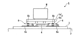
本実施形態の免震装置Aは、図1から図3に示すように、精密機器Mが載置される矩形盤状の免震床本体1a及びこの免震床本体1aが上載されて一体に繋がる略矩形枠状で盤状のフレーム1bからなる免震床1と、免震床1の下方に配置され、例えば工場の床F上に固設された基台(下部構造)3と、免震床1と基台3の間に介装され、地震発生時に地震動(振動エネルギー)を吸収する減衰力及び免震床1を元の位置に戻す復元力を発生させるための複数のオイルダンパ4及びばねダンパ5(減衰・復元機構)と、免震床1と基台3の間に介装され、免震床1及び精密機器Mを水平面上で移動自在に支持して免震性能を付与するガイドレール支承6と、例えば精密機器M自身の加振力などによって生じる微振動を基台3に伝達して支持するための剛すべり支承7とを備えて構成されている。ここで、複数のオイルダンパ4及びばねダンパ5は、一端を免震床1(フレーム1b)に、他端を基台3に繋げるように設けられ、地震時に減衰力及び復元力を好適に発生させるように適宜配置されている。
As shown in FIG. 1 to FIG. 3, the seismic isolation device A of the present embodiment has a rectangular disk-shaped seismic isolation floor
本実施形態のガイドレール支承6は、平面視略矩形盤状に形成された免震床1の4つの角部側にそれぞれ配設されている。また、各ガイドレール支承6は、水平の一方向に延び、基台3に固設されたX軸レール6aと、このX軸レール6aに直交する水平の他方向に延び、免震床1(フレーム1b)に固設されたY軸レール6bと、上端がY軸レール6bに、下端がX軸レール6aにそれぞれ各レール6a、6bに沿って進退自在に繋がる連結支持部材6cとで構成されている。このように構成したガイドレール支承6によって、免震床1及び精密機器Mは、床F及び基台3に対し、水平面上を移動自在に支持(免震支承)されるとともに、上下に剛接合され上下方向の移動が規制されている。
The
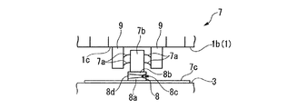
一方、本実施形態の剛すべり支承7は、図1に示すように、免震床1の中心を挟んで両側端側の外側にそれぞれ1つずつ対称配置されている。また、これら剛すべり支承7は、それぞれ、図2及び図4に示すように、免震床1に板バネ7aを介して支持され、板バネ7aによって下方に付勢された上部すべり部材7bと、免震床1の下方に配された基台3上に固設された下部すべり部材7cと、上部すべり部材7bと下部すべり部材7cの間に介装された上下に伸縮可能な伸縮部材8とを備えて構成されている。また、このように板バネ7aが繋がって下方に付勢された上部すべり部材7bは、下部すべり部材7cとの間に介装した伸縮部材8を下方に押圧し、この伸縮部材8を通じて、板バネ7aの付勢に応じた押付力(支承面圧)で下部すべり部材7cを押圧するように設けられている。
On the other hand, as shown in FIG. 1, the rigid
さらに、本実施形態においては、図1、図2及び図4に示すように、免震床1の両側端側のフレーム1bから水平方向外側に延びる延出部材1cに上端が繋がり下方に延びる支持部材9が設けられており、板バネ7aが、その一端をこの支持部材9に、他端を上部すべり部材7bに繋げて設けられている。これにより、上部すべり部材7bが、板バネ7a、支持部材9及び延出部材1cを介して免震床1(フレーム1b)に支持され、このように構成した剛すべり支承7は、板バネ7aによって水平方向の剛性が微振動を確実に基台3に伝達して支持させることができるように固定されている。
Furthermore, in this embodiment, as shown in FIGS. 1, 2 and 4, the upper end is connected to the extending
また、本実施形態の伸縮部材8は、レベリングブロックであり、図4に示すように、下部すべり部材7c上に置かれた状態で、上面がテーパー面とされた下側ブロック8aと、下側ブロック8aの上方に上下動可能に設けられ、下面がテーパー面とされた上側ブロック8bと、上下両ブロック8a、8bの間に配されて各ブロック8a、8bのテーパー面に上下のテーパー面をそれぞれ接触して設けられるとともに、調整ボルト8cを回転操作によって左右に進退する楔状の滑動ブロック8dとを備えて構成されている。そして、このように構成した伸縮部材8は、調整ボルト8cを例えば正転させると滑動ブロック8dが進出移動し、上側ブロック8bを上方に押し上げられるように移動させる。また、調整ボルト8cを逆転すると滑動ブロック8dが退避移動し、上側ブロック8bを下げるように移動させる。すなわち、調整ボルト8cの回転操作によってその上下方向に伸縮自在とされ、このような伸縮部材8によって、板バネ7aで付勢された上部すべり部材7bから伸縮部材8を介して下部すべり部材7cに作用する押付力(支承面圧)が調整できる。
Further, the
ついで、上記の構成からなる免震装置Aの作用及び効果について説明する。 Next, the operation and effect of the seismic isolation device A having the above configuration will be described.
はじめに、地震が発生した際には、床Fに地震動が伝達するとともに、その振動エネルギーが床Fを通じて免震装置Aに伝達される。このとき、従来と同様に、フレーム1b(免震床1)に繋げて設けられたオイルダンパ4やばねダンパ5に減衰力及び回復力が発生して振動エネルギーが吸収される。
First, when an earthquake occurs, the ground motion is transmitted to the floor F and the vibration energy is transmitted to the seismic isolation device A through the floor F. At this time, as in the prior art, damping force and recovery force are generated in the
また、本実施形態においては、免震床1がガイドレール支承6によって支持されているため、連結支持部材6cがX軸レール6a及びY軸レール6bに沿ってそれぞれ進退するように移動する。これにより、免震床1は、精密機器Mが載置されて偏在荷重が顕著である場合においても、水平面上を自在に移動し、このように移動することで、免震床1の固有周期が地震動の卓越周期帯域から長周期側にずらされ、応答加速度が小さくなる。
In this embodiment, since the
また、本実施形態において、ガイドレール支承6を免震床1の4つの角部側にそれぞれ設けて免震床1を支持しているため、地震動の振動エネルギーが伝達した際に、それぞれのガイドレール支承6によって上記のように水平面上を自在に移動することで、偏在荷重が作用していても免震床1に大きな捩れが発生することがない。さらに、それぞれのガイドレール支承6によって上下方向の移動を規制して免震床1が支持されているため、地震動によって免震支承が上方に引き抜かれるように動くこともなく、免震床1が上下に動くことも確実に防止される。
In this embodiment, since the
よって、この免震床1に載置された精密機器Mは、従来からこの種の免震装置Aに具備されるオイルダンパ4やばねダンパ5とともにガイドレール支承6を備えることによって、地震動によって倒れたりすることがなく、確実に地震による損傷が防止されて保護される。そして、本実施形態の免震装置Aによって地震による精密機器Mの損傷が防止されることで、被災後の事業の復旧や回復を早期に図ることができ、BCP(事業継続計画)の観点からも好適に免震化が図られることになる。
Therefore, the precision device M placed on the
なお、ガイドレール支承6は、確実に免震床1の捩れを防止しつつ免震床1を水平面上で自在に移動させることができれば、その設置位置や数を限定する必要はない。そして、このようなガイドレール支承6は、免震床1を構築して精密機器Mの免震化を図る際に、精密機器Mの配置によって偏在荷重が顕著になったり、免震床1の施工時点において最終的な精密機器Mの配置が決まらず、免震床1の荷重分布が決まっていなかったり、施工途中で精密機器Mの配置が変更され、荷重分布に変更が生じるような場合であっても、単に免震床1を水平面上で移動自在に支持すればよいため、容易に対応可能とされる。
Note that the
一方、精密機器Mを使用している通常のオペレーション時(通常時)には、例えば精密機器M自身から発せられる加振力や、フロアを人間が移動することによる加振力、工場の周囲を自動車などが走行することによる加振力などに伴う微振動が発生する。 On the other hand, during normal operation (normal time) using the precision instrument M, for example, the excitation force generated by the precision instrument M itself, the excitation force caused by the person moving on the floor, Micro-vibration occurs due to the excitation force caused by the traveling of an automobile or the like.
これに対し、本実施形態の免震装置Aにおいては、板バネ7aによって剛すべり支承7の上部すべり部材7bが支持されているため、伸縮部材8を伸縮させることで、この上部すべり部材7bから下部すべり部材7cへの押付力(支承面圧)が任意の大きさで調整できる。特に、免震床1を構築して精密機器Mの免震化を図る際に、精密機器Mの配置によって偏在荷重が顕著になったり、免震床1の施工時点においても最終的な精密機器Mの配置が決まらず、免震床1の荷重分布が決まっていなかったり、施工途中で精密機器Mの配置が変更され、荷重分布に変更が生じるような場合であっても、上部すべり部材7bが板バネ7aを介して免震床1に支持されていることで、上載荷重にかかわらず、支承面圧を所望の大きさに調整し、調整後の支承面圧を維持することができる。
On the other hand, in the seismic isolation device A of the present embodiment, since the upper sliding
そして、本実施形態においては、予め、伸縮部材8で板バネ7aの付勢力(押圧力)を調整して、支承面圧を調整し、地震に対しては摩擦が切れてすべるように、微振動による加振力に対しては上部すべり部材7b(伸縮部材8)と下部すべり部材7cとの摩擦が切れないようにしておく。これにより、偏在荷重や免震床の荷重分布の変更などによって、支承面圧を適切な値で維持できなくなることがなく、適正な減衰性能が発揮される。
In the present embodiment, the urging force (pressing force) of the
したがって、本実施形態の免震装置Aにおいては、ガイドレール支承6によって、免震床1が水平面上を移動自在に、且つ免震床1の上下方向の移動を規制して支持されることで、載置した精密機器Mにより免震床1に偏在荷重が生じる場合においても、この偏在荷重によって免震床1の地震時挙動に大きな捩れが生じることを防止できる。これにより、上載荷重にかかわらず免震床1ひいては精密機器Mを好適に免震支承することができる。
Therefore, in the seismic isolation device A of the present embodiment, the
また、剛すべり支承7の上部すべり部材7bが板バネ7aを介して免震床1に支持されていることで、上載荷重にかかわらず、この板バネ7aによる安定した押付力(支承面圧)で下部すべり部材7cを押圧することができ、さらに、剛すべり支承7の水平方向の剛性を確保することができる。これにより、地震に対してはすべるようにしてあるが、微振動のような小さい加振力に対しては剛性を確保したまま摩擦が切れないようにすることができる。
Further, since the upper sliding
また、このとき、伸縮部材8を伸縮させることで容易に上部すべり部材7bから下部すべり部材7cへの支承面圧を調整することができ、確実に、地震に対してはすべるようにしてあるが、微振動のような小さい加振力に対しては剛性を確保したまま摩擦が切れないようにすることができる。
Further, at this time, the support surface pressure from the upper sliding
よって、本実施形態の免震装置Aによれば、上載荷重にかかわらず、ガイドレール支承6によって免震床1ひいては精密機器Mを好適に免震支承することができ、剛すべり支承7によって安定した支承面圧を維持して確実に微振動のような小さい加振力に対しては剛性を確保したまま摩擦が切れないようにすることができるため、偏在荷重や免震床の荷重分布の変更などによって、支承面圧を適切な値で維持できなくなることがなく、適正な減衰性能を発揮する免震装置Aを提供することが可能になる。
Therefore, according to the seismic isolation device A of the present embodiment, the
以上、本発明に係る免震装置の実施形態について説明したが、本発明は上記の一実施形態に限定されるものではなく、その趣旨を逸脱しない範囲で適宜変更可能である。例えば、本実施形態では、精密機器Mを載置する免震床1が免震床本体1aとフレーム1bで構成され、また、ガイドレール支承6及び剛すべり支承7がフレーム1bと基台3に繋げられてこれらの間に介装されているものとしたが、免震床1は、必ずしもフレーム1bを備えて構成されていなくてもよく、また、基台3を設けなくてもよく、ガイドレール支承6及び剛すべり支承7を直接免震床本体1a(免震床1)や床F(下部構造)に繋げて、免震装置Aが構成されてもよい。
As mentioned above, although embodiment of the seismic isolation apparatus which concerns on this invention was described, this invention is not limited to said one Embodiment, In the range which does not deviate from the meaning, it can change suitably. For example, in this embodiment, the
また、本実施形態では、伸縮部材8がレベリングブロックであるものとしたが、上部すべり部材7bから所望の押付力を下部すべり部材7cに作用させるように上下に伸縮可能に構成されていれば、特にレベリングブロックに限定する必要はない。さらに、上部すべり部材7bと下部すべり部材7cの間に、必ずしも伸縮部材8が介装されていなくてもよく、上部すべり部材7bを直接下部すべり部材7cに接触させて押圧させるようにしてもよい。この場合、板バネ7aの変形量を、板バネ7aの弾発力の変動が小さい非線形ばね領域内に設定しておくことで、本実施形態と同様に、所望の押付力(支承面圧)で下部すべり部材7cを押圧し、これを維持することができる。
Further, in the present embodiment, the
また、本実施形態では、免震装置Aにオイルダンパ4やばねダンパ5が付加減衰として設けられているものとしたが、例えば積層ゴム支承など他の付加減衰が具備されてもよい。
In this embodiment, the
さらに、本実施形態では、免震装置Aによって精密機器Mをスポット的に免震化するものとして説明を行なったが、例えば工場の複数の精密機器Mが載置される床Fを免震床1として、フロアの床F全体の免震化に適用されてもよい。
Further, in the present embodiment, the description has been given on the assumption that the precision device M is spot-isolated by the seismic isolation device A. For example, a floor F on which a plurality of precision devices M in a factory are placed is used as a
1 免震床
1a 免震床本体
1b フレーム
3 基台(下部構造)
4 オイルダンパ
5 ばねダンパ
6 ガイドレール支承
6a X軸レール
6b Y軸レール
6c 連結支持部材
7 剛すべり支承
7a 板バネ
7b 上部すべり部材
7c 下部すべり部材
8 伸縮部材
A 免震装置
F 床
1 Base-isolated
4
Claims (2)
水平の一方向に延び、前記下部構造に固設されたX軸レールと、該X軸レールに直交する水平の他方向に延び、前記免震床に固設されたY軸レールと、上端が前記Y軸レールに、下端が前記X軸レールにそれぞれ前記各レールに沿って進退自在に繋がる連結支持部材とからなるガイドレール支承と、
作用した振動エネルギーを吸収する減衰力及び前記免震床を元の位置に戻す復元力を発生させる減衰・復元機構とを備えることを特徴とする免震装置。 An upper sliding member supported on the base isolation floor via a leaf spring and biased downward by the leaf spring, and a lower structure disposed below the base isolation floor and fixed to the upper sliding member From a rigid sliding bearing comprising a lower sliding member pressed by a pressing force according to the biasing force by the leaf spring that acts as a predetermined vibration energy and breaks friction ,
An X-axis rail extending in one horizontal direction and fixed to the lower structure; a Y-axis rail extending in another horizontal direction perpendicular to the X-axis rail and fixed to the base isolation floor; A guide rail support comprising a connecting support member connected to the Y-axis rail, the lower end of the Y-axis rail being connected to the X-axis rail so as to freely advance and retract, and
A seismic isolation device comprising: a damping force that absorbs applied vibration energy and a damping / restoring mechanism that generates a restoring force that returns the seismic isolation floor to its original position .
前記剛すべり支承が、上部すべり部材と前記下部すべり部材の間に介装され、上下に伸縮して前記板バネによる押圧力を調整するための伸縮部材を備え、
前記伸縮部材が、前記下部すべり部材上に置かれた状態で、上面がテーパー面とされた下側ブロックと、前記下側ブロックの上方に上下動可能に設けられ、下面がテーパー面とされた上側ブロックと、前記下側ブロックと前記上側ブロックの間に配され、左右に進退自在に設けられた楔状の滑動ブロックとを備えて構成されていることを特徴とする免震装置。 The seismic isolation device according to claim 1,
The rigid sliding support is interposed between the upper sliding member and the lower sliding member, and includes an expansion / contraction member for adjusting the pressing force by the leaf spring by vertically extending and contracting ,
The elastic member is placed on the lower sliding member, and is provided with a lower block whose upper surface is a tapered surface and a vertically movable upper surface above the lower block, and a lower surface is a tapered surface. A seismic isolation device comprising an upper block, and a wedge-shaped sliding block disposed between the lower block and the upper block and provided to be movable forward and backward .
Priority Applications (1)
| Application Number | Priority Date | Filing Date | Title |
|---|---|---|---|
| JP2009192303A JP5518399B2 (en) | 2009-08-21 | 2009-08-21 | Seismic isolation device |
Applications Claiming Priority (1)
| Application Number | Priority Date | Filing Date | Title |
|---|---|---|---|
| JP2009192303A JP5518399B2 (en) | 2009-08-21 | 2009-08-21 | Seismic isolation device |
Publications (2)
| Publication Number | Publication Date |
|---|---|
| JP2011042990A JP2011042990A (en) | 2011-03-03 |
| JP5518399B2 true JP5518399B2 (en) | 2014-06-11 |
Family
ID=43830591
Family Applications (1)
| Application Number | Title | Priority Date | Filing Date |
|---|---|---|---|
| JP2009192303A Active JP5518399B2 (en) | 2009-08-21 | 2009-08-21 | Seismic isolation device |
Country Status (1)
| Country | Link |
|---|---|
| JP (1) | JP5518399B2 (en) |
Families Citing this family (2)
| Publication number | Priority date | Publication date | Assignee | Title |
|---|---|---|---|---|
| JP6476714B2 (en) * | 2014-10-07 | 2019-03-06 | 村田機械株式会社 | Automatic warehouse |
| CN105402310A (en) * | 2015-12-08 | 2016-03-16 | 芜湖多维减震技术有限公司 | Sliding trolley type shock insulation stand seat and shock insulation method thereof |
Family Cites Families (2)
| Publication number | Priority date | Publication date | Assignee | Title |
|---|---|---|---|---|
| JPH09273593A (en) * | 1996-04-05 | 1997-10-21 | Mitsubishi Steel Mfg Co Ltd | Base-isolating device |
| JP3185703B2 (en) * | 1996-12-26 | 2001-07-11 | 株式会社大林組 | Vibration isolation device |
-
2009
- 2009-08-21 JP JP2009192303A patent/JP5518399B2/en active Active
Also Published As
| Publication number | Publication date |
|---|---|
| JP2011042990A (en) | 2011-03-03 |
Similar Documents
| Publication | Publication Date | Title |
|---|---|---|
| TWI284695B (en) | Isolation platform | |
| JP6372034B2 (en) | Anti-vibration vibration reduction device | |
| JP2009062733A (en) | Vertically-base-isolated structure | |
| US10718399B2 (en) | Anti-vibration support system | |
| JP5518399B2 (en) | Seismic isolation device | |
| KR101127938B1 (en) | Seismic isolating apparatus | |
| JP6991422B2 (en) | Vibration damping device for structures | |
| JP6796817B2 (en) | Seismic isolation mechanism | |
| KR102141780B1 (en) | Rail type hybrid sesimic isolation apparatus | |
| JP2004346562A (en) | Passive type two-stage vibration control device | |
| JPH1136657A (en) | Base isolation device | |
| KR200431157Y1 (en) | Bearing apparatus for structure | |
| JP6442934B2 (en) | Fail-safe device | |
| JP6483570B2 (en) | How to replace the seismic isolation device | |
| JP7129780B2 (en) | Floor seismic isolation system | |
| JP5721333B2 (en) | Sliding foundation structure | |
| JP2006029593A (en) | Vibration eliminating device | |
| JP5095015B1 (en) | Seismic isolation device | |
| JP5457997B2 (en) | Telescopic device for bridge | |
| JPS61130640A (en) | Seismic relief device for structure | |
| JP5327647B2 (en) | Damping structure | |
| JP6914407B2 (en) | Seismic isolation mechanism | |
| JP2019138376A (en) | Seismic isolation mechanism | |
| JP4953713B2 (en) | Seismic isolation system | |
| JP2016030917A (en) | Vibration isolation mechanism |
Legal Events
| Date | Code | Title | Description |
|---|---|---|---|
| A621 | Written request for application examination |
Free format text: JAPANESE INTERMEDIATE CODE: A621 Effective date: 20120511 |
|
| A711 | Notification of change in applicant |
Free format text: JAPANESE INTERMEDIATE CODE: A711 Effective date: 20120612 |
|
| A521 | Request for written amendment filed |
Free format text: JAPANESE INTERMEDIATE CODE: A821 Effective date: 20120612 |
|
| A977 | Report on retrieval |
Free format text: JAPANESE INTERMEDIATE CODE: A971007 Effective date: 20130627 |
|
| A131 | Notification of reasons for refusal |
Free format text: JAPANESE INTERMEDIATE CODE: A131 Effective date: 20130709 |
|
| A977 | Report on retrieval |
Free format text: JAPANESE INTERMEDIATE CODE: A971007 Effective date: 20130822 |
|
| A521 | Request for written amendment filed |
Free format text: JAPANESE INTERMEDIATE CODE: A523 Effective date: 20130909 |
|
| TRDD | Decision of grant or rejection written | ||
| A01 | Written decision to grant a patent or to grant a registration (utility model) |
Free format text: JAPANESE INTERMEDIATE CODE: A01 Effective date: 20140304 |
|
| A61 | First payment of annual fees (during grant procedure) |
Free format text: JAPANESE INTERMEDIATE CODE: A61 Effective date: 20140402 |
|
| R150 | Certificate of patent or registration of utility model |
Ref document number: 5518399 Country of ref document: JP Free format text: JAPANESE INTERMEDIATE CODE: R150 |
|
| S111 | Request for change of ownership or part of ownership |
Free format text: JAPANESE INTERMEDIATE CODE: R313115 |
|
| R350 | Written notification of registration of transfer |
Free format text: JAPANESE INTERMEDIATE CODE: R350 |
|
| R250 | Receipt of annual fees |
Free format text: JAPANESE INTERMEDIATE CODE: R250 |
|
| S531 | Written request for registration of change of domicile |
Free format text: JAPANESE INTERMEDIATE CODE: R313531 |
|
| S533 | Written request for registration of change of name |
Free format text: JAPANESE INTERMEDIATE CODE: R313533 |
|
| R350 | Written notification of registration of transfer |
Free format text: JAPANESE INTERMEDIATE CODE: R350 |
|
| R250 | Receipt of annual fees |
Free format text: JAPANESE INTERMEDIATE CODE: R250 |
|
| R250 | Receipt of annual fees |
Free format text: JAPANESE INTERMEDIATE CODE: R250 |
|
| R250 | Receipt of annual fees |
Free format text: JAPANESE INTERMEDIATE CODE: R250 |
|
| R250 | Receipt of annual fees |
Free format text: JAPANESE INTERMEDIATE CODE: R250 |
|
| R250 | Receipt of annual fees |
Free format text: JAPANESE INTERMEDIATE CODE: R250 |
|
| R250 | Receipt of annual fees |
Free format text: JAPANESE INTERMEDIATE CODE: R250 |
|
| R250 | Receipt of annual fees |
Free format text: JAPANESE INTERMEDIATE CODE: R250 |