JP5518053B2 - Method and apparatus for detecting respiratory pressure in an implantable stimulation system - Google Patents
Method and apparatus for detecting respiratory pressure in an implantable stimulation system Download PDFInfo
- Publication number
- JP5518053B2 JP5518053B2 JP2011509769A JP2011509769A JP5518053B2 JP 5518053 B2 JP5518053 B2 JP 5518053B2 JP 2011509769 A JP2011509769 A JP 2011509769A JP 2011509769 A JP2011509769 A JP 2011509769A JP 5518053 B2 JP5518053 B2 JP 5518053B2
- Authority
- JP
- Japan
- Prior art keywords
- sensor
- lead
- pressure
- wing
- temperature
- Prior art date
- Legal status (The legal status is an assumption and is not a legal conclusion. Google has not performed a legal analysis and makes no representation as to the accuracy of the status listed.)
- Active
Links
- 230000000241 respiratory effect Effects 0.000 title claims description 45
- 230000000638 stimulation Effects 0.000 title description 28
- 238000000034 method Methods 0.000 title description 17
- WABPQHHGFIMREM-UHFFFAOYSA-N lead(0) Chemical compound [Pb] WABPQHHGFIMREM-UHFFFAOYSA-N 0.000 claims description 32
- 230000029058 respiratory gaseous exchange Effects 0.000 claims description 23
- 238000001514 detection method Methods 0.000 claims description 22
- 238000004873 anchoring Methods 0.000 description 25
- 210000001519 tissue Anatomy 0.000 description 21
- 208000001797 obstructive sleep apnea Diseases 0.000 description 16
- 210000004224 pleura Anatomy 0.000 description 15
- 230000007246 mechanism Effects 0.000 description 14
- 238000010586 diagram Methods 0.000 description 13
- 210000004072 lung Anatomy 0.000 description 13
- 210000003281 pleural cavity Anatomy 0.000 description 13
- 230000003601 intercostal effect Effects 0.000 description 12
- 230000006641 stabilisation Effects 0.000 description 11
- 238000011105 stabilization Methods 0.000 description 11
- 238000007920 subcutaneous administration Methods 0.000 description 10
- 230000006870 function Effects 0.000 description 9
- 210000000038 chest Anatomy 0.000 description 8
- 230000033001 locomotion Effects 0.000 description 8
- 230000000737 periodic effect Effects 0.000 description 8
- 201000002859 sleep apnea Diseases 0.000 description 8
- 238000002513 implantation Methods 0.000 description 7
- 210000000845 cartilage Anatomy 0.000 description 6
- 238000001914 filtration Methods 0.000 description 6
- 230000003434 inspiratory effect Effects 0.000 description 6
- 230000008859 change Effects 0.000 description 5
- 230000007423 decrease Effects 0.000 description 5
- 210000002445 nipple Anatomy 0.000 description 5
- 210000001562 sternum Anatomy 0.000 description 5
- 238000002560 therapeutic procedure Methods 0.000 description 5
- 238000004891 communication Methods 0.000 description 4
- QTCANKDTWWSCMR-UHFFFAOYSA-N costic aldehyde Natural products C1CCC(=C)C2CC(C(=C)C=O)CCC21C QTCANKDTWWSCMR-UHFFFAOYSA-N 0.000 description 4
- 210000001169 hypoglossal nerve Anatomy 0.000 description 4
- ISTFUJWTQAMRGA-UHFFFAOYSA-N iso-beta-costal Natural products C1C(C(=C)C=O)CCC2(C)CCCC(C)=C21 ISTFUJWTQAMRGA-UHFFFAOYSA-N 0.000 description 4
- 238000012544 monitoring process Methods 0.000 description 4
- 210000003205 muscle Anatomy 0.000 description 4
- 210000005036 nerve Anatomy 0.000 description 4
- 230000007704 transition Effects 0.000 description 4
- 210000002808 connective tissue Anatomy 0.000 description 3
- 230000000875 corresponding effect Effects 0.000 description 3
- 230000000694 effects Effects 0.000 description 3
- 239000007943 implant Substances 0.000 description 3
- 208000008784 apnea Diseases 0.000 description 2
- 238000013459 approach Methods 0.000 description 2
- 239000011248 coating agent Substances 0.000 description 2
- 238000000576 coating method Methods 0.000 description 2
- 239000004020 conductor Substances 0.000 description 2
- 210000003238 esophagus Anatomy 0.000 description 2
- 238000007654 immersion Methods 0.000 description 2
- WABPQHHGFIMREM-NOHWODKXSA-N lead-200 Chemical compound [200Pb] WABPQHHGFIMREM-NOHWODKXSA-N 0.000 description 2
- 230000000414 obstructive effect Effects 0.000 description 2
- 210000002976 pectoralis muscle Anatomy 0.000 description 2
- 210000003516 pericardium Anatomy 0.000 description 2
- 230000008569 process Effects 0.000 description 2
- 238000012545 processing Methods 0.000 description 2
- 230000001902 propagating effect Effects 0.000 description 2
- 230000004202 respiratory function Effects 0.000 description 2
- 230000004044 response Effects 0.000 description 2
- 230000001360 synchronised effect Effects 0.000 description 2
- 230000001225 therapeutic effect Effects 0.000 description 2
- 210000000115 thoracic cavity Anatomy 0.000 description 2
- 210000003437 trachea Anatomy 0.000 description 2
- 206010013975 Dyspnoeas Diseases 0.000 description 1
- 206010038669 Respiratory arrest Diseases 0.000 description 1
- 206010067775 Upper airway obstruction Diseases 0.000 description 1
- 239000000853 adhesive Substances 0.000 description 1
- 230000001070 adhesive effect Effects 0.000 description 1
- 210000003484 anatomy Anatomy 0.000 description 1
- QVGXLLKOCUKJST-UHFFFAOYSA-N atomic oxygen Chemical compound [O] QVGXLLKOCUKJST-UHFFFAOYSA-N 0.000 description 1
- 230000003190 augmentative effect Effects 0.000 description 1
- 230000006399 behavior Effects 0.000 description 1
- 230000008901 benefit Effects 0.000 description 1
- 230000005540 biological transmission Effects 0.000 description 1
- 230000000903 blocking effect Effects 0.000 description 1
- 239000008280 blood Substances 0.000 description 1
- 210000004369 blood Anatomy 0.000 description 1
- 230000017531 blood circulation Effects 0.000 description 1
- 239000003795 chemical substances by application Substances 0.000 description 1
- 230000001276 controlling effect Effects 0.000 description 1
- 230000002596 correlated effect Effects 0.000 description 1
- 230000008878 coupling Effects 0.000 description 1
- 238000010168 coupling process Methods 0.000 description 1
- 238000005859 coupling reaction Methods 0.000 description 1
- 239000013078 crystal Substances 0.000 description 1
- 238000006073 displacement reaction Methods 0.000 description 1
- 239000013013 elastic material Substances 0.000 description 1
- 238000010292 electrical insulation Methods 0.000 description 1
- 210000003195 fascia Anatomy 0.000 description 1
- 238000002594 fluoroscopy Methods 0.000 description 1
- 230000004217 heart function Effects 0.000 description 1
- 238000003780 insertion Methods 0.000 description 1
- 230000037431 insertion Effects 0.000 description 1
- 210000000876 intercostal muscle Anatomy 0.000 description 1
- 239000000463 material Substances 0.000 description 1
- 238000005259 measurement Methods 0.000 description 1
- 238000002324 minimally invasive surgery Methods 0.000 description 1
- 238000012986 modification Methods 0.000 description 1
- 230000004048 modification Effects 0.000 description 1
- 230000001537 neural effect Effects 0.000 description 1
- 229910052760 oxygen Inorganic materials 0.000 description 1
- 239000001301 oxygen Substances 0.000 description 1
- 206010033675 panniculitis Diseases 0.000 description 1
- 210000000578 peripheral nerve Anatomy 0.000 description 1
- 239000010453 quartz Substances 0.000 description 1
- 230000003252 repetitive effect Effects 0.000 description 1
- 230000000630 rising effect Effects 0.000 description 1
- 230000035945 sensitivity Effects 0.000 description 1
- VYPSYNLAJGMNEJ-UHFFFAOYSA-N silicon dioxide Inorganic materials O=[Si]=O VYPSYNLAJGMNEJ-UHFFFAOYSA-N 0.000 description 1
- 210000004872 soft tissue Anatomy 0.000 description 1
- 230000000087 stabilizing effect Effects 0.000 description 1
- 230000004936 stimulating effect Effects 0.000 description 1
- 210000004304 subcutaneous tissue Anatomy 0.000 description 1
- 230000002277 temperature effect Effects 0.000 description 1
Images


Classifications
-
- A—HUMAN NECESSITIES
- A61—MEDICAL OR VETERINARY SCIENCE; HYGIENE
- A61B—DIAGNOSIS; SURGERY; IDENTIFICATION
- A61B5/00—Measuring for diagnostic purposes; Identification of persons
- A61B5/03—Detecting, measuring or recording fluid pressure within the body other than blood pressure, e.g. cerebral pressure; Measuring pressure in body tissues or organs
-
- A—HUMAN NECESSITIES
- A61—MEDICAL OR VETERINARY SCIENCE; HYGIENE
- A61B—DIAGNOSIS; SURGERY; IDENTIFICATION
- A61B5/00—Measuring for diagnostic purposes; Identification of persons
- A61B5/01—Measuring temperature of body parts ; Diagnostic temperature sensing, e.g. for malignant or inflamed tissue
-
- A—HUMAN NECESSITIES
- A61—MEDICAL OR VETERINARY SCIENCE; HYGIENE
- A61B—DIAGNOSIS; SURGERY; IDENTIFICATION
- A61B5/00—Measuring for diagnostic purposes; Identification of persons
- A61B5/08—Detecting, measuring or recording devices for evaluating the respiratory organs
- A61B5/0826—Detecting or evaluating apnoea events
-
- A—HUMAN NECESSITIES
- A61—MEDICAL OR VETERINARY SCIENCE; HYGIENE
- A61B—DIAGNOSIS; SURGERY; IDENTIFICATION
- A61B5/00—Measuring for diagnostic purposes; Identification of persons
- A61B5/48—Other medical applications
- A61B5/4806—Sleep evaluation
- A61B5/4818—Sleep apnoea
-
- A—HUMAN NECESSITIES
- A61—MEDICAL OR VETERINARY SCIENCE; HYGIENE
- A61N—ELECTROTHERAPY; MAGNETOTHERAPY; RADIATION THERAPY; ULTRASOUND THERAPY
- A61N1/00—Electrotherapy; Circuits therefor
- A61N1/18—Applying electric currents by contact electrodes
- A61N1/32—Applying electric currents by contact electrodes alternating or intermittent currents
- A61N1/36—Applying electric currents by contact electrodes alternating or intermittent currents for stimulation
- A61N1/3601—Applying electric currents by contact electrodes alternating or intermittent currents for stimulation of respiratory organs
-
- A—HUMAN NECESSITIES
- A61—MEDICAL OR VETERINARY SCIENCE; HYGIENE
- A61N—ELECTROTHERAPY; MAGNETOTHERAPY; RADIATION THERAPY; ULTRASOUND THERAPY
- A61N1/00—Electrotherapy; Circuits therefor
- A61N1/18—Applying electric currents by contact electrodes
- A61N1/32—Applying electric currents by contact electrodes alternating or intermittent currents
- A61N1/36—Applying electric currents by contact electrodes alternating or intermittent currents for stimulation
- A61N1/3605—Implantable neurostimulators for stimulating central or peripheral nerve system
- A61N1/36128—Control systems
- A61N1/36135—Control systems using physiological parameters
-
- A—HUMAN NECESSITIES
- A61—MEDICAL OR VETERINARY SCIENCE; HYGIENE
- A61N—ELECTROTHERAPY; MAGNETOTHERAPY; RADIATION THERAPY; ULTRASOUND THERAPY
- A61N1/00—Electrotherapy; Circuits therefor
- A61N1/18—Applying electric currents by contact electrodes
- A61N1/32—Applying electric currents by contact electrodes alternating or intermittent currents
- A61N1/36—Applying electric currents by contact electrodes alternating or intermittent currents for stimulation
- A61N1/362—Heart stimulators
- A61N1/365—Heart stimulators controlled by a physiological parameter, e.g. heart potential
- A61N1/36514—Heart stimulators controlled by a physiological parameter, e.g. heart potential controlled by a physiological quantity other than heart potential, e.g. blood pressure
- A61N1/36521—Heart stimulators controlled by a physiological parameter, e.g. heart potential controlled by a physiological quantity other than heart potential, e.g. blood pressure the parameter being derived from measurement of an electrical impedance
Description
本発明は、患者の軟組織を刺激し監視する移植可能な刺激システムに関し、より具体的には本発明は呼吸圧力を検出して神経組織に対する施療を制御する方法および装置に関するものである。 The present invention relates to an implantable stimulation system for stimulating and monitoring a patient's soft tissue, and more particularly, the present invention relates to a method and apparatus for detecting respiratory pressure and controlling treatment for neural tissue.
本出願は、2008年5月15日出願の米国仮特許出願第61/053,344号に基づき米国特許法第119条(e)項に規定された優先権を主張するものであり、同出願は参照により本明細書に組み込まれる。
睡眠時無呼吸とは、一般に睡眠中の呼吸停止を指す。閉塞性睡眠時無呼吸(OSA)と呼ばれる睡眠時無呼吸の一種は、上気道の閉塞および/または圧潰に起因する睡眠中の呼吸の反復的な中断によって特徴付けられ、通常は血中酸素飽和度の減少を伴う。
This application claims the priority prescribed in section 119 (e) of the US Patent Act based on US Provisional Patent Application No. 61 / 053,344 filed on May 15, 2008. Are incorporated herein by reference.
Sleep apnea generally refers to respiratory arrest during sleep. A type of sleep apnea, called obstructive sleep apnea (OSA), is characterized by repetitive interruptions in breathing during sleep due to upper airway obstruction and / or collapse, usually blood oxygen saturation Accompanied by a decrease in the degree.
閉塞性睡眠時無呼吸に対する治療の一つには、顎の下の首領域に位置する舌下神経への電気的刺激の付与が含まれていた。この種の刺激治療は、上気道の筋肉を活性化し上気道開存性を保つものである。睡眠時無呼吸の治療では、閉塞された気道を介する呼吸の困難さからもたらされる呼吸努力(呼吸のためのエフォート)の増大は、呼吸の吸息位相期間中に気道を開いたままに保つ上気道筋肉あるいは上気道筋肉群の同期刺激により回避される。たとえば、頤舌筋は睡眠時無呼吸の治療中に舌下神経周辺のカフ電極箇所により刺激を受ける。 One treatment for obstructive sleep apnea included the application of electrical stimulation to the hypoglossal nerve located in the neck region under the jaw. This type of stimulation therapy activates upper airway muscles and maintains upper airway patency. In the treatment of sleep apnea, increased respiratory effort (effort for breathing) resulting from difficulty breathing through an obstructed airway can help keep the airway open during the breathing inspiration phase. Avoided by synchronized stimulation of airway muscles or upper airway muscle groups. For example, the glossopharyngeal muscle is stimulated by cuff electrode locations around the hypoglossal nerve during sleep apnea treatment.
神経に対する治療を施す電極の位置決めに加え、閉塞性睡眠時無呼吸治療には、胸骨上切痕や気管と食道との間の空間等の胸膜腔に通ずる圧力を有する領域内に外科的に移植したセンサーの使用や、あるいは気管や食道のいずれかに取り付けたセンサーの使用が含まれることがある。このセンサーは、肋間に配置したり、胸骨柄後側の圧力を検出したりする位置に固定することもできる。胸骨上切痕と胸骨の胸骨柄は、胸膜腔に解剖学的に通ずる上側胸部の周知の構造である。胸膜腔圧力の変化が特徴的な呼吸努力波形をもたらし、そのため、センサーにより呼吸努力波形情報を利用して、増大した呼吸努力が判定できるようにして、そこでこの情報を用いて呼吸努力が増大したという判定に応答して施療を制御する。 In addition to positioning the electrodes to treat the nerve, for obstructive sleep apnea therapy, surgically implanted in an area with pressure leading to the pleural cavity, such as the suprasternal notch and the space between the trachea and esophagus Use of sensors that are attached to the trachea or esophagus. This sensor can also be fixed at a position where it can be placed between the ribs or the pressure on the posterior side of the sternum can be detected. The episternal notch and the sternum of the sternum are well known structures of the upper chest that anatomically communicate with the pleural space. Changes in pleural cavity pressure result in a characteristic respiratory effort waveform so that the sensor can use the respiratory effort waveform information to determine increased respiratory effort, where this information is used to increase respiratory effort. The treatment is controlled in response to the determination.
センサーの配置場所は、少なくとも一部が、遅延の関数として選択され、すなわち呼吸起点からセンサー位置まで伝搬する呼吸努力の圧力波特性に関連する伝搬時間の関数として選択される。選択された場所はまた、特定の場所で利用可能な被検出信号を得るのに必要な濾波量、すなわちたとえば心臓の鼓動波形を取り除くのに必要な濾波等の所望の被検出特性に関連する波形以外の波形を取り除くのに用いる濾波量の関数ともなる。 The location of the sensor is selected at least in part as a function of delay, i.e. as a function of propagation time related to the pressure wave characteristics of the respiratory effort propagating from the respiratory origin to the sensor location. The selected location is also the amount of filtering required to obtain the detected signal available at a particular location, i.e., the waveform associated with the desired detected characteristic, e.g., the filtering required to remove the heartbeat waveform. It is also a function of the amount of filtering used to remove other waveforms.
しかし、センサー配置用の従来の場所の一部において、被検出信号は、センサーに対して心嚢が密接しているため心嚢によりもたらされる追加の人工的な偽信号により汚染されがちとなる。加えて、既知の配置場所を用いるセンサーの移植は侵襲性処置となりがちである。 However, in some conventional locations for sensor placement, the detected signal is likely to be contaminated by additional artificial spurious signals provided by the pericardium due to the close proximity of the pericardium to the sensor. In addition, implanting sensors using known locations tends to be invasive procedures.
従って、睡眠時無呼吸の治療における有効な呼吸検出の提供には重要な課題が残されたままである。 Thus, an important challenge remains in providing effective respiration detection in the treatment of sleep apnea.
添付図面は、実施形態のさらなる理解を提供すべく含めたものであり、本明細書に組み込まれてその一部を構成する。図面は実施形態を例示するものであり、詳細な説明と併せ実施形態の原理の説明に役立つものである。他の実施形態および意図する実施形態の利点の多くは、下記の詳細な説明を参照することでより良く理解されるので、容易に理解されよう。図面の要素は、互いに必ずしも実寸とは限らない。類似の参照符号は、対応する同様の部分を指す。従って、本明細書の態様と特徴は、添付図面と併せ考察したときに下記の実施形態の詳細な説明を参照してより良く理解されるようになるにつれ理解されよう。 The accompanying drawings are included to provide a further understanding of the embodiments and are incorporated in and constitute a part of this specification. The drawings illustrate the embodiments and, together with the detailed description, serve to explain the principles of the embodiments. Many of the advantages of other embodiments and contemplated embodiments will be readily understood as they are better understood by reference to the following detailed description. The elements in the drawings are not necessarily to scale with each other. Similar reference signs refer to corresponding similar parts. Accordingly, aspects and features of the present specification will become better understood when considered in conjunction with the accompanying drawings when read in conjunction with the following detailed description of the embodiments.
下記の詳細な説明は本質的に単なる説明であって、本明細書や本明細書の実施形態の応用や用途を限定する意図はない。さらに、先行する技術分野や背景技術や概要あるいは下記の詳細な説明に示されたあらゆる表現され、あるいは示唆された理論により制限する意図はない。 The following detailed description is merely exemplary in nature and is not intended to limit the application or uses of the specification or the embodiments of the specification. Furthermore, there is no intention to be bound by any expressed or implied theory presented in the preceding technical field, background, brief summary or the following detailed description.
従って、下記の詳細な説明では、本明細書の一部を形成する添付図面に対し参照がなされ、図面には本発明をその中で実施する特定の実施形態を例示により図示してある。この点で、「上部」、「底部」、「前部」、「後部」、「先頭」、「末尾」等の方向性指示用語は、説明している図面の向きを参照して用いるものとする。実施形態の構成部品は多数の異なる方向性に配置することができ、方向性指示用語は例示目的に合わせかつ決して限定しないよう用いるものとする。本明細書の範囲から逸脱することなく、他の実施形態を活用でき、構造的なあるいは論理的な変形が可能であることは理解されたい。下記の詳細な説明は、それ故に限定的な意味に解釈すべきでなく、本発明範囲は添付特許請求の範囲にて規定されるものとする。 Accordingly, in the following detailed description, references are made to the accompanying drawings that form a part hereof, and in which is shown by way of illustration specific embodiments in which the invention may be practiced. In this regard, directional directive terms such as “top”, “bottom”, “front”, “rear”, “start”, “end” should be used with reference to the orientation of the drawing being described. To do. The components of the embodiments can be arranged in a number of different orientations, and the directionality terminology is intended to be illustrative and not limiting in any way. It should be understood that other embodiments may be utilized and structural or logical variations may be made without departing from the scope of the specification. The following detailed description is, therefore, not to be taken in a limiting sense, and the scope of the present invention is defined by the appended claims.
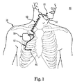
図1は、本明細書の一実施形態による移植可能な刺激システムの概略線図である。図1に示すように、本明細書の一実施形態による移植可能な刺激システム10の一例は、患者20の胸筋領域内に外科的に位置決めすることのできる移植可能なパルス発生器(IPG)55と、IPG55の接続ポート内に配置されたコネクタ(図示せず)を介してIPG55と電気的に結合する刺激リード線52とを含んでいる。リード線52は、電極あるいは電極システム65を含んでいて、IPG55から延在し、電極システム65が患者20の舌下神経53等の所望の神経近傍に位置づけられ、下記に詳しく説明するように、神経53の刺激が出来るようにしてある。一実施形態では、たとえばリード線52をその中で使用することのできる移植可能な刺激システムがChristophersonらに対する米国特許第6,572,543号に記載されていて、同特許は参照によりその全体を本明細書に組み込むものとする。この例示システムにあっては、センサーリード線57がIPG55に電気的に結合されており、IPG55から延在し、センサー変換器60が患者20内に配置されて呼吸努力を検出できるように構成されている。しかし、本明細書に説明する呼吸検出実施形態は、睡眠時無呼吸を治療する他の移植可能な刺激システムと共に用いることができることは理解されたい。
FIG. 1 is a schematic diagram of an implantable stimulation system according to one embodiment of the present specification. As shown in FIG. 1, an example of an
ある実施形態では、システム10はまた胸部領域周りに分散させられて経胸腔生体インピーダンス信号や心電図(ECG)信号や他の呼吸関連信号を計測する各種センサー等の呼吸機能に関連するさらなる生理学的データを取得する追加のセンサーを備える。
In certain embodiments, the
ある実施形態では、閉塞性睡眠時無呼吸を治療する検出および刺激システムは、閉塞性睡眠時無呼吸であると診断された患者に対する治療解決策をもたらす全体的に移植可能なシステムである。他の実施形態では、患者の身体内にはシステムの1以上の構成部品を移植はしない。この種の非移植構成部品の数個の非限定的実施例には、外部センサー(たとえば、インピーダンスや心拍数等)や外部処理装置や外部電源が含まれる。無論、システムの移植されたシステムが、システムの外部部分に対しシステムの移植部分との間で双方向にデータおよび/または制御信号の伝送を可能にする通信路を提供することを、さらに理解されたい。通信路は、高周波(RF)遠隔通信リンクや他の無線通信プロトコルを含む。 In certain embodiments, the detection and stimulation system for treating obstructive sleep apnea is a totally implantable system that provides a therapeutic solution for patients diagnosed with obstructive sleep apnea. In other embodiments, one or more components of the system are not implanted in the patient's body. Some non-limiting examples of such non-implanted components include external sensors (eg, impedance, heart rate, etc.), external processing devices, and external power sources. Of course, it is further understood that the implanted system of the system provides a communication path that allows transmission of data and / or control signals bidirectionally to and from the exterior portion of the system. I want. The communication path includes a radio frequency (RF) telecommunications link or other wireless communication protocol.
部分的に移植可能または全体的に移植可能であるかによらず、システムは呼吸中に舌下神経を刺激し、それによって睡眠中に上気道内の閉塞あるいは遮蔽を防止するよう設計してある。一実施形態では、移植可能なシステムは移植可能なパルス発生器(IPG)と、抹消神経カフ刺激リード線と呼吸検出リード線とを備える。 Regardless of whether it is partially implantable or fully implantable, the system is designed to stimulate the hypoglossal nerve during breathing, thereby preventing obstruction or shielding in the upper airway during sleep . In one embodiment, the implantable system comprises an implantable pulse generator (IPG), a peripheral nerve cuff stimulation lead, and a respiratory detection lead.
一実施形態では、図2に関連してさらに説明するように、センサー60は胸膜腔内配置あるいは胸膜外配置(これに限定はしないが肋間配置を含む)を介して胸膜に通ずる圧力を有する領域内に外科的に移植する呼吸圧力センサーである。センサー60の配置場所は少なくとも一部において、遅延の関数として選択されるものであり、すなわち呼吸起点からセンサー位置まで伝搬する呼吸努力の圧力波特性に関連する伝搬時間の関数として選択される。選択された場所はまた、特定の場所で利用可能な被検出信号を得るのに必要な濾波量あるいは信号処理量、すなわち、たとえば心臓の鼓動波形を取り除くのに必要な濾波等の所望の被検出特性に関連する波形以外の波形を取り除くのに必要な濾波量の関数ともなる。センサー60の配置により、IPG55は呼吸努力波形情報を受け取り、この情報を用いて施療を制御できるようになる。
In one embodiment, as described further in connection with FIG. 2, the
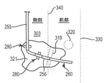
図2に概略的に示すように、本明細書の一実施形態では、移植可能な刺激システム10は呼吸圧力センサー71を胸膜腔90内に配置してセンサー71が肺80の近傍に密接配置されるよう構成したリード線75を含む検出システム70を備える。この構成では、センサー71は胸膜における呼吸圧力に対し直接結合されるようになる。別の態様では、胸膜腔90は体壁側胸膜78と肺側胸膜79との間の内腔を含む。最後に、図2が隣り合う解剖学的構造間の十分な空間を例示目的に合わせ示すものであると理解されよう。
As shown schematically in FIG. 2, in one embodiment herein, the
一実施形態では、リード線75は、センサー71をその先端に支持するリード線本体72と、リード線本体72の基端部寄りに配置する係留具74(翼様固定部材等)とを含んでいる。係留具74は、センサー71が該センサー71の移植に続き肺80に沿って対向するようセンサーの隔膜部を配向する位置決めされた状態を保つよう保証する。IPG55(図1)がセンサー71からのセンサー波形を受け取るように、リード線本体72は肋間空間91を介して胸膜腔90内に配置され(参照符号88により示すようにセンサー71とリード線本体72の位置とともに)、それによりIPG55(図1)が本明細書の実施形態による治療処置療法に従い吸息に同期して電気的刺激を送出できる。
In one embodiment, the
さらに図2に示されるように、リード線本体72が肋間空間(たとえば、2本の肋骨86の間)を通って延出し、センサー71を位置決めし、概ねインジケーター90を介して示すように胸膜腔内に配置されるよう、リード線75を挿入する。一実施形態では、リード線75には封止された筺体内に装着された圧電水晶が組み込んであり、呼吸に関連する胸郭内圧力を監視することができる。他の実施形態では、呼吸圧力の監視には、(胸郭内の圧力を監視することに加えあるいはこれに代って)呼吸圧力を示す他の生理学的データの監視が含まれる。センサー71はIPG55(図1)により給電され、IPG55はまたリード線75からの呼吸信号を受け取って処理する内部回路網を収容している。
As further shown in FIG. 2, the
一実施形態では、システムはセンサー71が胸膜腔内に配置されている箇所から遠隔的(数cmほどの距離)に位置するリード線係留具74を含んでいる。センサーとリード線に対する組織の動きは、リード線移動/駆逐のみならず不要な信号成分もまた誘発することがあり、それ故に、リード線75が胸部内腔に侵入する箇所近くへのリード線本体72の係留が保証される。このことを念頭に、係留具74は移植中に肋間筋肉や筋膜等の皮下結合組織に縫合させることとし、係留具74はリード線本体72に固定あるいは固着されて摺動できないようにする。
In one embodiment, the system includes a
他の実施形態では、呼吸センサーは空気流センサー、圧力センサー、体積センサー、加速度計、音響センサー、温度センサー、機械的変形センサー、作用力(エフォート)センサーのうちの任意の1つとすることができる。 In other embodiments, the respiration sensor can be any one of an air flow sensor, a pressure sensor, a volume sensor, an accelerometer, an acoustic sensor, a temperature sensor, a mechanical deformation sensor, an effort sensor. .
図1と図2に関連して図示し説明した位置へのセンサー60の配置を達成するのに、少なくとも図3と図4に関連して例示する幾つかの異なる手法を用いることができる。
Several different approaches illustrated at least in connection with FIGS. 3 and 4 can be used to achieve the placement of the
図3は、本明細書の一実施形態により皮下胸膜外配置を用いる移植可能な刺激システム150を概略的に示すものである。図3に示すように、システム150はIPG155とセンサーリード線161とを含んでいる。一実施形態では、IPG155はIPG55(図1)と少なくとも実質的に同じ特徴と属性とを含む。
FIG. 3 schematically illustrates an
概括的に言うならば、センサーリード線161は、センサーリード線161についてより短い長さを有する点を除き、図1と図2に関連して先に説明したように、センサー60と実質同様の方法で呼吸努力を検出および/または計測するよう構成してある。このことを念頭に、図3に示すように、センサーリード線161はセンサー部160とリード線本体164と安定化機構162とを含んでいる。一態様では、リード線本体164は比較的短い長さを有し、概ね1本以上の肋骨(たとえば、肋骨86A,86B等)上にIPG155を装着した状態で、リード線本体164がIPG155の導線端取付板156から直接延出する略直線状の部分を形成し、リード線本体164が肋骨86A,86Bに略平行に延在するようにする。ある実施形態においては、リード線本体164が図3に示すものを上回る長さを有することは理解されたい。
Generally speaking,
図3に示すように、センサーリード線161は体壁側胸膜78の外側にある(図2)皮下胸膜外領域89(これも、これに限定はしないが一対の肋骨86間の肋間配置を含む)に移植される。この皮下胸膜外位置89において、センサー部160は体壁側胸膜78に対向させるか、あるいは体壁側胸膜78の外側にあって隣り合う一対の肋骨間にアクセス可能な組織(これは、何層かの筋肉と関連する結合組織とを含む)内に設けることができる。一態様では、この構成においてセンサー部160は胸部内腔90に存在する呼吸圧力に対し間接的に結合されるようになる。
As shown in FIG. 3, the
この構成では、センサーリード161はその同じ肋骨対86A,86Bの間のセンサー部160にて終端する。換言すれば、センサーリード線161は隣り合う肋骨86A,86B間のIPG155から発し、センサーリード線161が略直線状をなす状態で、センサーリード線161全体は肋骨間のこの皮下空間91A内に止まる。従って、本実施形態では、センサーリード線161はこの皮下空間91Bに対し上方(頭の方向)あるいは下方(足の方向)のいずれにも肋骨86A,86Bを越えて延在はしない。
In this configuration, the
概括的に言って、センサーリード線161の安定化機構162はセンサー部160が目標場所に概ね固定された状態に止まり、センサー部160の隔膜部がセンサー160の移植に続いて肺に沿って対向配置されるよう保証する。弾性材料から作成することで、安定化機構162はその位置を保持しあるいは維持するに十分な剛性を依然持たせたまま、その配置を容易にし、かつ周囲の組織に干渉しないほど十分な可撓性を有する。この固定位置において、(図2に関連して先に説明したように)センサー部160は胸膜腔内あるいは胸膜外の移植構成のいずれにおいても肋骨86A,86B間に配置される。
Generally speaking, the
一実施形態では、安定化機構162は、図5と図6に関連して以下に詳細に説明するように、センサー部160の両側から横方向外方へ延出する一対の翼を含む。他のある実施形態では、安定化機構162は図7と図8に関連して以下に詳細に説明するように、センサーリード線161の両側から横方向外方へ延出する1以上の係留具要素(たとえば、アーム)を備える。一態様では、安定化機構162のこれらの翼あるいはアームはセンサー部160の横方向のずれを阻止しかつ/または回動を阻止し、センサー部160の機能部分が胸膜と肺とに対向して配向されるよう保証する。
In one embodiment, the
センサーリード線の胸膜腔内配置(図2の実施形態に準ずる)を達成する他の手法の一つが、本明細書の一実施形態に従い図4に関連して概略例示してある。図4に示すように、移植可能な刺激システム170はIPG175とセンサーリード線181とを含んでいる。一実施形態では、IPG175はIPG55(図1)と少なくとも実質同じ特徴と属性とを含んでいる(図1)。
One of the other approaches to achieving sensor lead intrapleural placement (similar to the embodiment of FIG. 2) is schematically illustrated in connection with FIG. 4 according to one embodiment of the present specification. As shown in FIG. 4,
概括的に言って、センサーリード線181はセンサーリード線181がより短い長さを有する点を除き、図1と図2に関連して先に説明したように、センサー60と実質同様の方法で呼吸努力を検出しかつ/または計測するよう構成されている。このことを念頭に、図3に示すように、センサーリード線181はセンサー部180とリード線本体185(基端リード線部分184と先端リード線部分186とを有する)と安定化機構188とを含んでいる。一態様では、リード線本体185に比較的短い長さを持たせ、概ね一対の肋骨86A,86B上にIPG155を装着した状態で、基端リード線部分184がIPG155の導線端取付板176から直接延出する略直線状の部分を形成し、基端リード線部分184が離間する肋骨86A,86B(これらは、図9Aに関連して以下により詳細に説明するように、胸骨柄95に個別に繋がっている)間に略平行に延在させている。
Generally speaking, the
一態様では、安定化機構188(たとえば、図7の係留具280)を基端リード線部分184に沿って配置し、基端リード線部分184を皮下組織あるいは隣接組織に対し固定する。別の態様では、基端リード線部分184を安定化機構188を介して係留させた状態で、先端リード線部分186が基端リード線部分184に対し略垂直の角度を形成し、これにより先端リード線部分186が(図2に示すように)胸膜腔内のセンサー部180で終端する前に1本以上の肋骨86D,86Eの下側を下方へ延在するよう配置する。
In one aspect, a stabilizing mechanism 188 (eg,
この構成にあっては、先端リード線部分186は肋骨の長手方向軸に対し(あるいは患者の身長の長手方向軸に対し)略垂直に配向され、センサー部180を胸膜90(図2)内に略垂直方向に保持する(図2)。この配向により、呼吸中に肺80の略垂直方向(頭に向かう方向、または頭から離れる方向)の通常の周期的な動きがセンサー部180が行なう検出に実質影響を及ぼさないよう保証され、それはセンサー部180の長手方向軸が肺の動きの方向に沿って(これを横断することなく)整列するからである。
In this configuration, the
それでも、他のある実施形態では、センサー部180は先端リード部分186が肋骨の長手方向軸に略平行に延びる状態で胸膜腔内に移植され、センサー部180を胸膜90内の略水平な位置に配向することができる。これらの実施形態では、センサー部180近傍の先端リード線部分186の一部が、図1または図3に図示したものと実質同様の方法で隣り合う一対の肋骨間に配置され、これに略平行に延在する。
Still, in certain other embodiments, the
ある実施形態では、図4の実施形態の安定化機構188は図3の実施形態の安定化機構162(あるいは図5の翼様部材220がもたらす安定化機構)と交換可能であり、逆も可能である。
In some embodiments, the
数ある特徴の中で、図3,4の実施形態はIPGとそのセンサーリード線の比較的簡単な移植を可能にしている。IPGとセンサーリード線の患者の身体の右側への移植が好ましいが、他のある実施形態ではIPGとセンサーリード線の移植は患者の身体の左側に行なうことができる。 Among other features, the embodiment of FIGS. 3 and 4 allows for relatively simple implantation of the IPG and its sensor leads. While it is preferred to implant the IPG and sensor lead to the right side of the patient's body, in certain other embodiments, the IPG and sensor lead can be implanted to the left side of the patient's body.
図5は、本明細書の一実施形態によるセンサーリード線200を概略示す平面図である。概括的に言って、センサーリード線200は、少なくとも図3に関連して先に説明したのと実質同様の方法で、その移植場所にセンサー部210の位置を安定化するよう構成した一対の翼様部材220を含むセンサー部210を備える。図5に示すように、センサーリード線200はリード線本体202とセンサー部210とを備える。リード線本体202は、センサー部210を支持する先端部206と、中間部205と、図1のIPG55まで延在(して接続)するよう構成した基端部204とを含んでいる。
FIG. 5 is a plan view schematically illustrating a
一態様では、センサー部210は、好ましくはX線透視検査や他の放射線透視技法により可視化できるよう放射線不透過性の低い材料で作成した先端214を含む。別の態様では、センサー部210は翼様部材220を含んでいて、これがセンサー部210の両側から外方へ延在している。翼様部材220は様々な形状をとらせることができるが、図6に示す部材220は先細の形状を有していて、ここでは各部材220が概ね幅広の基部221を有するとともに、翼様部材220は湾曲先端223に向かって漸次幅狭となるようにしてある。図6の断面図にさらに示すように、翼様部材220は概ね平坦な断面形状を有する。しかし、ある実施形態では、基部221を先端223よりも厚肉とし、センサー部220の本体に対する部材220の頑丈な取り付けを保証する。
In one aspect,
一実施形態では、翼様部材220は組織に対する翼様部材220の縫合を容易にする構成の如何なる孔も他の特徴(あるいは他の係着技法)も含まない。その代りに、センサー部210から外方へ延在する翼様部材220の概ね大きな表面積と弾性とが周囲の組織に対し摩擦係合と物理的な当接とをもたらす。こうして、翼様部材220はセンサー部210の位置を検出対象である組織に対し適切な方向に保持する機構を提供する。特に、ある実施形態では、センサー部210は方向性検出素子212(点線で図示)を含んでいて、移植済みのセンサー部210がこの方向性検出素子212を胸膜および標的肺組織とに対向させる。この構成では、翼様部材220は標的組織から方向性検出素子が回動離間しないようにし、一方またその身体内の移植位置に対するセンサー部210の上方や下方や左方や右方への移動を阻止する。
In one embodiment, wing-
別の態様では、センサー素子212は圧力検出を行なう構成としてあり、このセンサー素子212は、図10〜図12に関連して後程より詳細に説明するように、1以上の圧電性結晶素子を含む電子センサー素子を備える。
In another aspect, the
図7は、本明細書の一実施形態によるセンサーリード線250を概略示す平面図である。図7に示すように、センサーリード線250はリード線本体252とセンサー部260とを備える。一実施形態では、センサーリード線250は少なくとも図1と図2に関連して先に説明したようにセンサー60と実質同じ特徴と属性とを備える。図7に示すように、センサー部260は先端264とセンサー素子262とを含む。一態様では、センサー部260は略1〜3cmの長さ(D4)を有する。
FIG. 7 is a plan view schematically illustrating a
リード線本体252は、中間部255と基端部254と先端部256とを含んでいる。先端部256はセンサー部260を支持しており、一方で基端部254はIPG55まで延出させてこれに接続する構成としてある(図1)。
The lead wire
ある実施形態では、センサーリード線250はリード線本体252に装着するかあるいはその一部として形成する第1の係留素子280を含む。一態様では、第1の係留素子280はリード線本体252の長さに対し固定位置を有し、係留素子280の中央部282の両側から外方へ延出する一対のアーム284を含む。この位置では、アーム284はリード線本体252の長手方向軸に略垂直に延在する。一実施形態では、図8の側面図に示すように、各アーム284はリード線本体252の直径に実質満たない肉厚を有する。
In some embodiments, the
他の態様では、各アーム284は周囲の組織に対するアーム284の縫合(あるいは他の係着技法)を容易にする構成とした孔285を含む。ある実施形態では、リード線本体252に沿う第1の係留素子280の固定位置は先端264から略4〜9cmの距離(D1)に離間している。他の実施形態では、距離(D1)は略2〜6cmである。一態様では、この構成がセンサーリード線250を胸腔あるいは肋間腔内に適切な距離だけ延在させ、センサーリード線をその肋間展開から駆逐させないようにしつつ最適の検出が達成できるよう保証する。さらに、弾性アーム284は、センサー部の回動運動を阻止しかつ/またはセンサー部260の実質的な横方向のずれを阻止することで方向性センサー部260の方向を維持して肺や胸膜に対向させる。しかし、センサーリード線は図9Aと図9Bに関連してさらに説明することにするように、心臓機能との干渉を排除するに十分なほどかなり短くしてある。
In other aspects, each
ある実施形態では、固定の第1の係留素子280に加え、センサーリード線250は図7に示すように第2の係留素子290を含んでいる。一態様では、該第2の係留素子290はリード線本体252の長さに沿って可動とし、第2の係留素子290を周囲の組織に対し固定する前にその位置が調整できるようにしてある。この構成では、個々の係留素子280,290の間の距離(D2)は、センサーリード線250の確固たる移植を達成すべく所望に応じて変えることができる。一つの非限定的な使用時に、第2の係留素子290はIPG55(図1)の移植場所へおよび/またはそこから身体の側面303に沿って貫通させた後、センサーリード線250の基端部254を固定するよう構成する。
In some embodiments, in addition to the fixed first anchoring
一態様では、その可動位置(図7の方向を示す矢印Mにより表わされる)以外は、第2の係留素子290は第1の係留素子280と実質同じ特徴と属性とを有する。従って、第2の係留素子290は中央部292の両側から外方へ延出する一対のアーム294を有する。
In one aspect, the
しかし、他の実施形態では、第2の係留素子290にリード線本体252の長さに沿った固定位置を持たせ、個々の係留素子280,290間の距離(D2)が変わらないようにできることを理解されたい。
However, in other embodiments, the
ある実施形態では、リード線本体252はセンサー部260の外径を上回らない外径を含む。さらに、ある実施形態では、検出を行なおうとする標的組織に対する所望場所にセンサー部260を保持するのを容易にすべく、リード線本体252のセンサー部260と先端部256とを希釈した医用接着剤を用いて浸液塗装を施すことは理解されよう。同時に、浸液塗装はセンサー表面を柔らかくもし、さらなる電気的な絶縁をもたらす。
In some embodiments, the
胸膜腔内(あるいは胸膜に隣接させるも胸腔内)にセンサー部260を挿入することになるため、装置の可撓性を最適化すべくリード線本体252の外径を最小化しなければならないこと(図11に示したリード線本体導体406と足並みを揃えて)は理解されよう。この構成は、胸膜腔内のセンサー部260に対するどのような局部的な応力も最小化するよう機能する。同様に、センサーリード線250とセンサー部260を胸膜外構成内で展開させる状況にあっては、そのときはセンサー部260の比較的小さな外径が胸膜に対する応力を最小化することになる。
Since the
図9Aは、本明細書の一実施形態による移植可能な刺激システムのセンサーリード線250の移植方法300を概略示す正面図である。図9Aに示すように、IPG55は業界周知の方法で患者の胸筋領域(図1)に移植され、IPG55が胸郭302の(上部肋骨2や3等の)一対の肋骨304上に位置決めされるようにする。ある実施形態では、IPG55は心臓H(点線で図示)が位置する左側(L)に概ね対向させて患者の右側(R)上に移植する。図9Aをさらに参照するに、センサーリード線250はIPG55から延出し、一方で刺激リード線(図示せず)はセンサーリード線250とは反対方向にIPG55から延出させ、標的神経に結合させる。
FIG. 9A is a front view that schematically illustrates a
図9Aに示すように、各肋骨304は肋軟骨連結部308を介して肋軟骨306に接合する。各肋軟骨306は、胸骨柄310に接合される。方法300の一実施形態では、センサーリード250は少なくとも図2〜図4に関連して先に説明したのと実質同じく、肋間部内配置を介してセンサー部260を位置決めするよう移植する。 しかし、加えて、方法300に示すように、リード線本体252の基端部254を胸郭302の側部303を下方へ(かつ本体の長手方向の軸に略平行に)延在させ、リード線本体252の先端部256を基端部254に略平行に延在させる。この構成では、先端部256とセンサー部260は肋骨304に略平行に延在する。一態様では、センサー部260が肋軟骨連結部308に対し側方に(本体の外側に向け)配置されるよう、肋間侵入点319を選択する。ある実施形態では、センサー部260は乳頭320の真下あるいは下側に配置する。乳頭はセンサー部260の位置に機能的には無関係であるが、乳頭320が本体の側面と本体の中線との間の所望位置に対する位置決め用目印をもたらす。特に、方法300は、患者が睡眠をとるべく身体の側面を下に横たわっているときに、側面303の場所がセンサー部260からの読み取り精度を損なうために、センサーリード線250とセンサー部260を側面303から離して移植する工程を含む。同時に、方法300はセンサー部260の読み取りに対する心臓の鼓動の影響を最小化すべく、出来るだけ心臓から側方と長手方向の両方に離してセンサー部260を移植する工程を含んでいる。図9Aは、5番目と6番目の肋骨304間のセンサー部260の配置を示すものであるが、他の実施形態では、センサー部260の配置が1番目の高さの肋骨304から7番目の高さの肋骨304までの範囲にある肋骨群304内の任意の一対の隣り合う肋骨間で行なうこともできることが理解されよう。
As shown in FIG. 9A, each
さらに、ある実施形態では、方法300はまた呼吸の効果と機能の代表的計測値を取得すべく、適当な体積の肺組織上にセンサー部260を移植する工程を含んでいる。この後者の制約が、本実施形態ではセンサー部260が肺組織の一部に被せなければならないことになるために、センサー部260を心臓Hから離間配置できる距離を実際に制限する。
Further, in some embodiments, the
これらの制約を全て合わせることで、センサーリード線250は5番目の肋骨と6番目の肋骨との間に長手方向に(肺組織の対応部分の上に)センサー部260を配置するよう移植される。同時に、センサー部260は5番目あるいは6番目の肋骨のいずれかの肋軟骨連結部208の側方(本体の側部向き)に配置され、センサー部260はまた乳頭の真下あるいは内側に配置される。しかし、他のある実施形態では、1番目から7番目までの肋骨空間内、より好ましくは2番目から6番目の肋骨空間内等の異なる隣接肋骨群の間に、センサーリード線250とセンサー部260を展開させることができる。
By combining all these constraints, the
さらに、図9Aに示したこの位置決めを用いることで、第1の係留具280(これ自体はリード線本体252に固定)は、体壁側胸膜78(図2)の外部にあってセンサー部260の肋骨間挿入場所319の側方にある皮下胸膜外組織領域89内の本体の側面303の固定位置に固定される。別の態様では、第2の係留具290をIPG55寄りに接近配置し、前記したように、本体の側面303に固定する。第2の係留具290は可動であるため、第2の係留具290を固定する位置を変え、第1の係留具280の被固定位置もまた支持したまま、リード線250の基端部254の安定性を最適化することができる。第2の係留具290の所望位置が一旦達成されると、縫合あるいは他の係着機構を用い第2の係留具290をリード線本体252と皮下結合組織とに対し固定する。
Furthermore, by using this positioning shown in FIG. 9A, the first anchoring device 280 (which itself is fixed to the lead wire main body 252) is outside the body wall side pleura 78 (FIG. 2) and the
ある実施形態では、乳頭320下方(すなわち、足向き)のセンサー部260の展開位置は、機能上の配慮を担うものである。特に、5番目と6番目の肋骨間(あるいは6番目と7番目の肋骨間)の胸膜外領域89内の肋間にセンサーリード線250とセンサー部260を展開させることで、胸筋を貫通したり侵害したりすることが回避でき、それによって最小の侵襲性処置を遂行し、胸膜90に対しセンサー部260を配置することができる。
In an embodiment, the deployed position of the
図9Bは、図9Aのように胸郭を示さずに、切開領域321に対するセンサーリード線250とセンサー部260の位置を概略示す線図である。図9Bに示すように、第1と第2の係留具280,290を身体の側部303に配置し、センサー部260を近くの肋骨の肋軟骨連結部(点線330で表わす)に対し側方に位置決め(本体の外側に)できるようにする。さらに、第1の係留具280を肋間侵入場所319外部の身体組織に対し配置して固定し、リード線の先端部256を肋間侵入場所319に挿通し、センサー部260を胸郭90内(図2参照)かあるいは隣り合う肋骨間の皮下胸郭外領域89内(たとえば、図3または図9A参照)に配置する。
FIG. 9B is a diagram schematically illustrating the positions of the
図10は、本明細書の一実施形態による移植可能な刺激システム用のリード線350のセンサー部360を概略示す斜視図である。一実施形態では、センサー部360は本明細書に前記したように、センサー部60,260と少なくとも実質的に同じ特徴と属性とを有する。図10に示すように、センサー部360はリード線本体の先端部356により支持され、他端に先端364を含む。一態様では、センサー部360は凹部370を有する上部361と、底部362とを備える。
FIG. 10 is a perspective view schematically illustrating a
概括的に言って、凹部370を介してセンサー部360は方向性センサーリード線を提供し、この凹部370が検出方向あるいは検出方位を規定する。先に説明した図3の翼162あるいは図5の翼220を参照するに、これらの翼は検出対象である標的組織に対向する凹部370を所望の方向に保持するよう機能する。
Generally speaking, the
一実施形態では、凹部370が隔膜部372の両側の一対の傾斜壁374間に挿入されている隔膜部372を定義する。隔膜部372は、センサー部360の筺体412内に収容されたセンサー素子400の一部を形成する。
In one embodiment, a
図11は、図10の線11−11による断面図であり、図12は図10の線12−12による側断面図であり、共に本明細書の一実施形態によるセンサー素子400を概略示すものである。一態様では、この断面図は点線の隔膜部372を表わす。図11と図12に示すように、センサー素子400は隔膜部372を挿通するかあるいはそれに沿う被検出変化を計測するよう構成した圧力検出素子402(たとえば、圧力変換器)と、温度を計測するよう構成した温度検出素子404(たとえば、温度変換器)とを収容した筺体412を備える。一実施形態では、圧力検出素子402は、圧力検出素子402用の温度補償装置として機能する温度検出素子404に電気的に結合する。一態様では、温度検出素子404を隔膜部372と圧力検出素子402とから離間させて配置し、これによりこれら個別の検出素子402,402が積層構成ではなく互いに側方に離間するようにする。
11 is a cross-sectional view taken along line 11-11 in FIG. 10, and FIG. 12 is a side cross-sectional view taken along line 12-12 in FIG. 10, both schematically illustrating a
ある実施形態では、温度の影響を相殺するために、温度検出素子404が圧力検出素子402に電気的に結合されており、それにより温度ではなく圧力における変化を主に示す被検出呼吸信号を生成するセンサー素子400形成される。
In some embodiments, the
しかし、圧力検出素子402を圧電素子で構成したときに、圧力検出素子402が圧力の変化よりも温度の変化に対し実質的により敏感となることもまた理解されたい。従って、他のある実施形態では、温度の影響を相殺する試みの代りに、圧電準拠圧力検出素子402を介して検出される温度変化を閉塞性睡眠時無呼吸事象が発生しているかどうかの判定における一要因として用いる。図12,13,17に関連して後程より詳細に説明するように、閉塞性睡眠時無呼吸事象を識別すべく、圧力信号とは無関係にあるいはこれと共に温度信号を用いることができる。
However, it should also be understood that when the
センサー素子400はまた、圧力検出素子402と温度検出素子404とを介して計測される信号を処理あるいは増幅するトランジスター408を含んでいる。ある実施形態では、圧力検出素子402および/または温度検出素子404は圧電変換器とする。一態様では、個々の素子402,404は密閉された筺体412から電気的な接続出力を提供するリード線250のセンサー部260の導電性配信素子406と電気的な連通状態とする。この配信素子406は、片やIPG55(図1)に信号を送信し、呼吸状態あるいは呼吸努力を指示する。
The
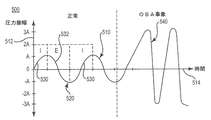
ある実施形態では、圧力検出素子402と温度検出素子404から生成された呼吸関連信号は図13と図14に示すように独立して描かれる。 図13に示すように、線図500は時間(514)に対する圧力(512)として写像した信号510を示す。信号510は吸息(I)と呼息(E)の周期的パターンを含んでいて、線図500はまた正常な呼吸期間中(信号部分520)と閉塞性無呼吸(OSA)事象(信号部分540)期間中のこれらのパターンの特性を示している。正常な呼吸期間中は、信号部分520は吸息部分530と呼息部分532とを含んでいて、それらは正常な振幅(A)を有し、かつ呼吸圧力の概ね均一な周期的振幅に対応している。しかし、OSA事象期間中は、信号部分540は呼吸圧力の実質的により大きな振幅(3Aすなわち非限定実施例における公称振幅Aの3倍等)を表わし、閉塞事象期間中の呼吸周期の吸息位相と呼息位相を通じての増大した呼吸努力を示す。従って、圧力信号の周期的な振幅のこれらの劇的な変化は閉塞性睡眠時無呼吸の検出および/または睡眠時無呼吸を治療する刺激治療のトリガーに用いられる。
In one embodiment, the breathing related signals generated from the
図14に示すように、線図550は時間(564)に対する温度(562)として描かれた信号560を示す。信号560は吸息(I)と呼息(E)の周期的パターンを含んでおり、線図550はまた正常な呼吸期間中(信号部分570)と閉塞性無呼吸(OSA)事象期間中(信号部分590)のこれらのパターンの特性を示す。正常な呼吸中は、信号部分570は吸息部分580と呼息部分582とを含んでおり、それらは名目上の振幅(A)を有し、被検出温度の略均一な周期的振幅に対応する。しかし、OSA事象期間中は、信号部分590は呼吸周期の吸息位相と呼息位相との間で温度の周期的振幅のピーク間に差異を殆ど見せず、空気流の減少を示す。従って、温度信号の周期的な振幅における差異の欠如を用い、閉塞性睡眠時無呼吸を検出しかつ/または睡眠時無呼吸を治療する刺激治療をトリガーする。
As shown in FIG. 14, diagram 550 shows signal 560 drawn as temperature (562) versus time (564).
この種の温度信号が呼吸状態(正常対閉塞)に関する有用な情報を提供するため、上述のセンサー素子400からなる実施形態の一つは圧力検出素子404とは無関係に、すなわち圧力信号に対する温度の影響を補償しないで、温度検出素子404を使用している。この温度信号は、独立とするか、あるいは圧力信号と組み合わせることができる。さらに、これら実施形態の一つは、圧電検出素子402を圧力とは別に温度センサーとしてだけ用いる。
Since this type of temperature signal provides useful information regarding the respiratory condition (normal vs. occlusion), one embodiment of the
図15は、図11と図12のセンサー素子400等のセンサー素子を介して温度と圧力を計測し、検出された呼吸信号620を生成する等価回路600を概略表わす線図である。図15に示すように、回路600は第1の圧電素子610と第2の圧電素子612とトランジスター614(たとえば、トランジスター増幅回路)とを含む。一実施形態では、局部組織の温度630(センサー素子400が移植済みで配向済みである場合)は、第1の圧電素子610を介しかつ第2の圧電素子612を介して検出される。同様に、局部組織の圧力632(センサー素子400が移植済みで配向済みである場合)は、第2の圧電素子612を介して検出される。この構成にあっては、(第1の検出素子610を介して捕捉される)圧力信号と(第2の検出素子612を介して捕捉される)温度信号は、1個の信号620へ集計される。一実施形態では、第1と第2の圧電素子610,612を互いに電気的に結合し、第2の圧電素子による圧力検出に対する温度の影響の相殺を可能とする。
FIG. 15 is a diagram that schematically represents an
別の実施形態では、図16に概略示すように、被検出呼吸信号670を生成する等価回路650はただ1個の圧電素子660とトランジスター増幅器614とを含んでいる。本実施形態では、局部組織温度630と局部圧力632(センサー素子400が移植されて配向されている場合)は共に1個の圧電素子660を介して検出される。ある実施形態では、異なる場所と異なる大きさおよび/または異なる極性の接続を有する圧電素子の様々な組み合わせを創成し、温度応答と圧力応答の規模を策定しうることがさらに理解されよう。
In another embodiment, as schematically illustrated in FIG. 16, an
他のある実施形態では、図15の回路600と図16の回路を共に単一のセンサー筺体内に実装するが、この構成では、被検出圧力信号と被検出温度信号は互いに別個にIPG55へ送ることになる筈である。
In some other embodiments, both the
ある実施形態では、温度信号と圧力信号は2つの別個の信号としてパルス発生器(たとえば、図1のIPG55)へ入力として供給し、最大の信号コンテンツを保存しうる。
In some embodiments, the temperature signal and the pressure signal may be provided as inputs to a pulse generator (eg,
図17は、(吸息710と呼息720の周期を介する)独立した呼吸温度信号702の圧力信号704(吸息710と呼息720の周期を介する)に対する併置を概略示す線図700である。図17に示すように、呼吸710中に、温度は降温区間730において(空気温度に起因して)下降し、昇温区間732において(血流に起因して)上昇する。同様に、呼吸710中に、圧力は負圧区間740において上昇し、正圧区間742において下降する。図17に示すように、温度信号702の最低値731は圧力信号704のピーク741と同時に発生する。一態様では、本実施形態では、圧電素子を適当な極性をもって装着して接続し、吸息中に温度を降温させ、吸息中に負圧を追加させる。こうして、追加の温度信号と圧力信号とを創成することができる。
FIG. 17 is a diagram 700 that schematically illustrates the juxtaposition of an independent breathing temperature signal 702 (through an
このような方法において、温度や圧力のような両変換器からの信号は、組み合わせて活用するか、あるいは独立型の構成にあっては別個に活用するかのいずれかとし、治療を施すべきかどうか判定することができる。たとえば(信号を別個に活用する例では)、圧力が所定の圧力閾値を超えて上昇していると判定され、同時に肺への空気流の制限あるいは妨害に起因して温度変化が一切検出されない場合、閉塞が発生したと判定し、そしてそのために、検出された閉塞に基づいて治療が施され、増強される。 In such a method, the signals from both transducers, such as temperature and pressure, should be used in combination, either in combination or separately in a stand-alone configuration. It can be determined. For example (in the case of separate signal utilization), when it is determined that the pressure is rising above a certain pressure threshold and no temperature change is detected due to restriction or blockage of airflow to the lungs at the same time It is determined that an occlusion has occurred, and therefore treatment is provided and augmented based on the detected occlusion.
しかし、圧力が所定の圧力閾値を超えて上昇していると判定され、一方で同時に温度もまた所定の温度閾値を超えて上昇していると判定された場合(これは、閉塞ではなく深い呼吸を示す)、そのとき、治療は見送られ得る。別の選択肢として、こうした状況下で、たとえば動作センサーからの入力のように、閉塞が発生し治療が始まったと推断させるさらなる指標を施療前に要求することもできる。 However, if it is determined that the pressure has risen above a predetermined pressure threshold, while at the same time the temperature is also determined to have increased above a predetermined temperature threshold (this is not an obstruction, but a deep breath The treatment can then be deferred. As an alternative, under these circumstances, further indications may be required prior to treatment, such as for example input from motion sensors, to infer that an occlusion has occurred and treatment has begun.
ある実施形態では、被検出温度信号を用いて被検出呼吸圧力の極性を指示し、それによって被検出呼吸圧力の呼息位相から吸息位相を差別化する。特に、図17に示すように、被検出温度信号の吸息と呼息のパターンは被検出呼吸信号の吸息と呼息のパターンと相関処理することができる。この構成は、検出された呼吸圧力信号が反転されるようになる幾つかの事例に有用である。この状況にあっては、被検出温度信号を用いて吸息と呼息の位相を差別化することで、IPG55は吸息位相と呼息位相および/または個々の吸息位相と呼息位相との間の遷移に対する電気的刺激の印加に適切に同期させることができる。
In some embodiments, the detected temperature signal is used to indicate the polarity of the detected respiratory pressure, thereby differentiating the inspiratory phase from the expiratory phase of the detected respiratory pressure. In particular, as shown in FIG. 17, the inspiration and expiration patterns of the detected temperature signal can be correlated with the inspiration and expiration patterns of the detected respiratory signal. This configuration is useful in some cases where the detected respiratory pressure signal becomes inverted. In this situation, the
図17に示す被検出呼吸圧力信号を参照するに、ピーク741が吸息位相(710)と呼息位相(720)との間の遷移領域(たとえば、吸息の終端および/または呼息の開始)に概ね対応することがさらに理解される。同様に、図17に示す被検出温度圧力信号をさらに参照するに、谷部731が吸息位相(710)と呼息位相(720)との間の遷移領域(たとえば、吸息の終端および/または呼息の開始)に概ね対応することが理解される。さらに、この種の遷移領域が吸息の開始と呼息の開始および他の関連する呼吸タイミング起点に関する情報を含むことが、当業者には理解されよう。一態様では、この情報はIPG55から刺激リード線への電気的な刺激信号の印加のトリガーあるいは同期に用いられる(図1)。
Referring to the detected respiratory pressure signal shown in FIG. 17,
センサーが影響を受ける圧力と温度は、センサー信号への潜在的入力源を示すものとして上記に提示したものである。呼吸運動や他の動きに関連する局部的な機械力等の他の入力もまた、考えうる。 The pressure and temperature at which the sensor is affected are those presented above as an indication of potential sources of sensor signal. Other inputs such as local mechanical forces related to respiratory motion and other movements are also conceivable.
本明細書の実施形態は、閉塞性睡眠時無呼吸事象に対する治療の検出および/またはトリガーに適した呼吸努力の正確な検出をもたらす。圧力および/または温度に対する感度をもって検出素子は呼吸行為の確固たる捕捉をもたらし、閉塞性睡眠時無呼吸事象の存否をより正確に示し、それによってより効果的な施療に通ずる。 Embodiments herein provide accurate detection of respiratory effort suitable for detecting and / or triggering treatment for an obstructive sleep apnea event. With sensitivity to pressure and / or temperature, the sensing element provides a robust capture of breathing behavior, more accurately indicating the presence or absence of an obstructive sleep apnea event, thereby leading to more effective treatment.
前述の説明では少なくとも1つの例示実施形態を提示してきたが、変形例が存在することは理解されたい。1または複数の例示実施形態は例示に過ぎず、本明細書の範囲や適用可能性や構成を限定する意図が如何なる形であれないことも理解されたい。むしろ、前述の説明は1または複数の例示実施形態を実装するための便利な道筋を当業者に提供するものである。本明細書の範囲から逸脱することなく要素の機能と配置において様々な変形が可能であることを、理解されたい。 While at least one exemplary embodiment has been presented in the foregoing description, it should be understood that variations exist. It should also be understood that the exemplary embodiment or exemplary embodiments are only examples, and are not intended to limit the scope, applicability, or configuration of the specification in any way. Rather, the foregoing description provides those skilled in the art with convenient routes for implementing one or more example embodiments. It should be understood that various modifications can be made in the function and arrangement of elements without departing from the scope of the specification.
Claims (4)
リード線本体と、先端を含むセンサー部とを含み、前記センサー部が、前記リード線本体から前記先端の方に延出し、第1の係留具及び少なくとも圧力変換器を含み、前記圧力変換器が前記センサー部の単一側の呼吸圧力を感知するよう構成された方向性検出素子で定義されるセンサーリード線、を備え
前記第1の係留具は、一対の分かれた、弾性の翼を有しており、前記一対の翼における各翼が前記リード線本体と前記センサー部の長手方向の軸に対して概ね直交して延びて、前記一対の翼が前記センサー部の両側から外方に向かってそれぞれが反対方向に延設されており、
前記各翼は外側先端と、前記外側先端より広い基部とを有し、それぞれの前記翼の前記基部が前記センサー部の両側のそれぞれの一方に接続しており、
前記翼は、縫合孔を有しておらず、標的組織に対して、摩擦係合し、及び物理的に当接する大きさ及び形状の表面を有し、前記方向性検出素子が前記標的組織に対向して留まるように、前記標的組織から前記方向性検出素子が回動離間しないよう構成されているセンサーシステム。 An implantable respiratory sensor system,
A lead body, and a sensor portion including a distal end, the sensor unit extends towards the tip from the lead body comprises a first anchor and at least a pressure transducer, the pressure transducer said first tether comprises a sensor lead, which is defined by the configured direction detecting device to sense the breathing pressure of the single side of the sensor section, possess divided the pair, the elasticity of the wings Each of the pair of wings extends substantially perpendicular to the longitudinal axis of the lead wire body and the sensor unit, and the pair of wings outward from both sides of the sensor unit. Each is extended in the opposite direction,
Wherein each wing includes an outer tip, and a said wider outer tip base, and the base of each of said blades is connected to one each of both sides of the sensor unit,
The wing does not have a suture hole, has a surface of a size and shape that frictionally engages and physically contacts the target tissue, and the directional detection element is attached to the target tissue . as remain oppositely, the sensor system wherein the directional sensing element is configured so as not to rotate away from the target tissue.
Applications Claiming Priority (3)
| Application Number | Priority Date | Filing Date | Title |
|---|---|---|---|
| US5334408P | 2008-05-15 | 2008-05-15 | |
| US61/053,344 | 2008-05-15 | ||
| PCT/US2009/044207 WO2009140636A2 (en) | 2008-05-15 | 2009-05-15 | Method and apparatus for sensing respiratory pressure in an implantable stimulation system |
Related Child Applications (1)
| Application Number | Title | Priority Date | Filing Date |
|---|---|---|---|
| JP2014075355A Division JP5800942B2 (en) | 2008-05-15 | 2014-04-01 | Method and apparatus for detecting respiratory pressure in an implantable stimulation system |
Publications (3)
| Publication Number | Publication Date |
|---|---|
| JP2011520526A JP2011520526A (en) | 2011-07-21 |
| JP2011520526A5 JP2011520526A5 (en) | 2012-06-21 |
| JP5518053B2 true JP5518053B2 (en) | 2014-06-11 |
Family
ID=40873477
Family Applications (2)
| Application Number | Title | Priority Date | Filing Date |
|---|---|---|---|
| JP2011509769A Active JP5518053B2 (en) | 2008-05-15 | 2009-05-15 | Method and apparatus for detecting respiratory pressure in an implantable stimulation system |
| JP2014075355A Active JP5800942B2 (en) | 2008-05-15 | 2014-04-01 | Method and apparatus for detecting respiratory pressure in an implantable stimulation system |
Family Applications After (1)
| Application Number | Title | Priority Date | Filing Date |
|---|---|---|---|
| JP2014075355A Active JP5800942B2 (en) | 2008-05-15 | 2014-04-01 | Method and apparatus for detecting respiratory pressure in an implantable stimulation system |
Country Status (6)
| Country | Link |
|---|---|
| US (3) | US20110152706A1 (en) |
| EP (3) | EP3708219B1 (en) |
| JP (2) | JP5518053B2 (en) |
| AU (1) | AU2009246179A1 (en) |
| CA (1) | CA2724335A1 (en) |
| WO (1) | WO2009140636A2 (en) |
Families Citing this family (58)
| Publication number | Priority date | Publication date | Assignee | Title |
|---|---|---|---|---|
| US20050149132A1 (en) | 2003-12-24 | 2005-07-07 | Imad Libbus | Automatic baroreflex modulation based on cardiac activity |
| WO2007098202A2 (en) | 2006-02-16 | 2007-08-30 | Imthera Medical, Inc. | An rfid based apparatus, system, and method for therapeutic treatment of a patient |
| US9589686B2 (en) | 2006-11-16 | 2017-03-07 | General Electric Company | Apparatus for detecting contaminants in a liquid and a system for use thereof |
| US20110320142A1 (en) * | 2010-06-28 | 2011-12-29 | General Electric Company | Temperature independent pressure sensor and associated methods thereof |
| US9538657B2 (en) | 2012-06-29 | 2017-01-03 | General Electric Company | Resonant sensor and an associated sensing method |
| US9658178B2 (en) | 2012-09-28 | 2017-05-23 | General Electric Company | Sensor systems for measuring an interface level in a multi-phase fluid composition |
| US9536122B2 (en) | 2014-11-04 | 2017-01-03 | General Electric Company | Disposable multivariable sensing devices having radio frequency based sensors |
| US10914698B2 (en) | 2006-11-16 | 2021-02-09 | General Electric Company | Sensing method and system |
| US20100198103A1 (en) | 2007-10-09 | 2010-08-05 | Imthera Medical, Inc. | System and method for neural stimulation |
| CA2722982A1 (en) | 2008-05-02 | 2009-11-05 | Medtronic, Inc. | Self expanding electrode cuff |
| US8340785B2 (en) | 2008-05-02 | 2012-12-25 | Medtronic, Inc. | Self expanding electrode cuff |
| EP3708219B1 (en) | 2008-05-15 | 2022-08-03 | Inspire Medical Systems, Inc. | Apparatus for sensing respiratory pressure in an implantable stimulation system |
| WO2010039853A1 (en) | 2008-10-01 | 2010-04-08 | Inspire Medical Systems, Inc. | Transvenous method of treating sleep apnea |
| BRPI0920548B8 (en) | 2008-10-09 | 2021-06-22 | Imthera Medical Inc | device to control the position of a patient's tongue |
| WO2010059839A2 (en) * | 2008-11-19 | 2010-05-27 | Inspire Medical Systems, Inc. | Method of treating sleep disordered breathing |
| US8515520B2 (en) | 2008-12-08 | 2013-08-20 | Medtronic Xomed, Inc. | Nerve electrode |
| JP2012521864A (en) | 2009-03-31 | 2012-09-20 | インスパイア・メディカル・システムズ・インコーポレイテッド | Percutaneous access method in a system for treating sleep-related abnormal breathing |
| US10751537B2 (en) | 2009-10-20 | 2020-08-25 | Nyxoah SA | Arced implant unit for modulation of nerves |
| US10716940B2 (en) | 2009-10-20 | 2020-07-21 | Nyxoah SA | Implant unit for modulation of small diameter nerves |
| US9409013B2 (en) | 2009-10-20 | 2016-08-09 | Nyxoah SA | Method for controlling energy delivery as a function of degree of coupling |
| BR112012010986A2 (en) | 2009-11-10 | 2016-04-12 | Imthera Medical Inc | system to stimulate a hypoglossal nerve to control a patient's tongue position |
| US9888864B2 (en) | 2010-03-12 | 2018-02-13 | Inspire Medical Systems, Inc. | Method and system for identifying a location for nerve stimulation |
| US8983572B2 (en) | 2010-10-29 | 2015-03-17 | Inspire Medical Systems, Inc. | System and method for patient selection in treating sleep disordered breathing |
| US8542023B2 (en) | 2010-11-09 | 2013-09-24 | General Electric Company | Highly selective chemical and biological sensors |
| EP2741813B1 (en) * | 2011-08-11 | 2022-03-09 | Inspire Medical Systems, Inc. | System for selecting a stimulation protocol based on sensed respiratory effort |
| US8934992B2 (en) | 2011-09-01 | 2015-01-13 | Inspire Medical Systems, Inc. | Nerve cuff |
| US8983611B2 (en) | 2011-09-27 | 2015-03-17 | Cardiac Pacemakers, Inc. | Neural control of central sleep apnea |
| US11253712B2 (en) | 2012-07-26 | 2022-02-22 | Nyxoah SA | Sleep disordered breathing treatment apparatus |
| US9907967B2 (en) | 2012-07-26 | 2018-03-06 | Adi Mashiach | Transcutaneous power conveyance device |
| US10052097B2 (en) | 2012-07-26 | 2018-08-21 | Nyxoah SA | Implant unit delivery tool |
| WO2014016693A2 (en) | 2012-07-26 | 2014-01-30 | Adi Mashiach | Electrical contacts on a medical device patch |
| DE112013004129T5 (en) | 2012-08-22 | 2015-05-21 | General Electric Company | Wireless system and method for measuring an operating condition of a machine |
| US10598650B2 (en) | 2012-08-22 | 2020-03-24 | General Electric Company | System and method for measuring an operative condition of a machine |
| US10684268B2 (en) | 2012-09-28 | 2020-06-16 | Bl Technologies, Inc. | Sensor systems for measuring an interface level in a multi-phase fluid composition |
| WO2015004540A2 (en) | 2013-06-17 | 2015-01-15 | Adi Mashiach | Dynamic modification of modulation throughout a therapy period |
| WO2016037144A2 (en) | 2014-09-04 | 2016-03-10 | AtaCor Medical, Inc. | Cardiac pacing lead delivery system |
| US9636505B2 (en) | 2014-11-24 | 2017-05-02 | AtaCor Medical, Inc. | Cardiac pacing sensing and control |
| US10743960B2 (en) | 2014-09-04 | 2020-08-18 | AtaCor Medical, Inc. | Cardiac arrhythmia treatment devices and delivery |
| US10328268B2 (en) | 2014-09-04 | 2019-06-25 | AtaCor Medical, Inc. | Cardiac pacing |
| US11097109B2 (en) | 2014-11-24 | 2021-08-24 | AtaCor Medical, Inc. | Cardiac pacing sensing and control |
| CN107864617B (en) | 2015-03-19 | 2021-08-20 | 启迪医疗仪器公司 | Stimulation for treating sleep disordered breathing |
| CN108289632B (en) | 2015-11-11 | 2021-08-13 | 启迪医疗仪器公司 | Heart and sleep monitoring |
| EP3377168B1 (en) | 2015-11-17 | 2023-06-21 | Inspire Medical Systems, Inc. | Microstimulation sleep disordered breathing (sdb) therapy device |
| WO2017100691A1 (en) * | 2015-12-09 | 2017-06-15 | The Alfred E. Mann Foundation For Scientific Research | Implantable pressure sensors and medical devices |
| AU2017252643B2 (en) | 2016-04-19 | 2022-04-14 | Inspire Medical Systems, Inc. | Accelerometer-based sensing for sleep disordered breathing (SDB) care |
| EP3537961A1 (en) | 2016-11-10 | 2019-09-18 | The Research Foundation for The State University of New York | System, method and biomarkers for airway obstruction |
| WO2018132713A1 (en) * | 2017-01-12 | 2018-07-19 | Tc1 Llc | Driveline bone anchors and methods of use |
| US10792407B2 (en) | 2017-01-12 | 2020-10-06 | Tc1 Llc | Percutaneous driveline anchor devices and methods of use |
| WO2019032890A1 (en) | 2017-08-11 | 2019-02-14 | Inspire Medical Systems, Inc. | Cuff electrode |
| WO2020102193A1 (en) | 2018-11-13 | 2020-05-22 | Inspire Medical Systems, Inc. | Multiple type sleep apnea |
| EP3920790A1 (en) | 2019-02-05 | 2021-12-15 | Inspire Medical Systems, Inc. | Implant-access incision and sensing for sleep disordered breathing (sdb) care |
| US11672975B2 (en) | 2019-05-29 | 2023-06-13 | AtaCor Medical, Inc. | Implantable electrical leads and associated delivery systems |
| EP4003158A1 (en) | 2019-07-25 | 2022-06-01 | Inspire Medical Systems, Inc. | Sleep detection for sleep disordered breathing (sdb) care |
| EP4003163A1 (en) | 2019-07-25 | 2022-06-01 | Inspire Medical Systems, Inc. | Respiration detection |
| US11666771B2 (en) | 2020-05-29 | 2023-06-06 | AtaCor Medical, Inc. | Implantable electrical leads and associated delivery systems |
| AU2021311610A1 (en) | 2020-07-24 | 2023-03-09 | Inspire Medical Systems, Inc. | Disease burden indication |
| US20220134102A1 (en) | 2020-11-04 | 2022-05-05 | Invicta Medical, Inc. | Implantable electrodes with remote power delivery for treating sleep apnea, and associated systems and methods |
| US20240116231A1 (en) | 2021-02-04 | 2024-04-11 | Inspire Medical Systems, Inc. | Implantable medical devices at least partially formed from a thermoset material |
Family Cites Families (112)
| Publication number | Priority date | Publication date | Assignee | Title |
|---|---|---|---|---|
| IT1156564B (en) * | 1982-03-16 | 1987-02-04 | Gianni Plicchi | IMPLANTABLE CARDIAC ELECTROSTIMULATOR, OF A PHYSIOLOGICAL TYPE, IN WHICH THE STIMULATION FREQUENCY IS REGULATED BY THE PATIENT'S RESPIRATORY FREQUENCY |
| US4813431A (en) * | 1987-07-22 | 1989-03-21 | David Brown | Intrapulmonary pressure monitoring system |
| US5098442A (en) * | 1989-12-06 | 1992-03-24 | Medtronic, Inc. | Muscle contraction control by intramuscular pressure monitoring |
| US5158080A (en) * | 1990-11-08 | 1992-10-27 | Medtronic, Inc. | Muscle tone |
| US5107856A (en) * | 1991-01-10 | 1992-04-28 | Siemens-Pacesetter, Inc. | Multiple lead suture sleeve |
| US5353800A (en) * | 1992-12-11 | 1994-10-11 | Medtronic, Inc. | Implantable pressure sensor lead |
| US5344438A (en) * | 1993-04-16 | 1994-09-06 | Medtronic, Inc. | Cuff electrode |
| US5423763A (en) * | 1993-06-17 | 1995-06-13 | Pacesetter, Inc. | Protective, visible suture sleeve for anchoring transvenous lead bodies |
| US5540731A (en) * | 1994-09-21 | 1996-07-30 | Medtronic, Inc. | Method and apparatus for pressure detecting and treating obstructive airway disorders |
| US5546952A (en) * | 1994-09-21 | 1996-08-20 | Medtronic, Inc. | Method and apparatus for detection of a respiratory waveform |
| US5485851A (en) * | 1994-09-21 | 1996-01-23 | Medtronic, Inc. | Method and apparatus for arousal detection |
| US5540733A (en) * | 1994-09-21 | 1996-07-30 | Medtronic, Inc. | Method and apparatus for detecting and treating obstructive sleep apnea |
| US5540732A (en) * | 1994-09-21 | 1996-07-30 | Medtronic, Inc. | Method and apparatus for impedance detecting and treating obstructive airway disorders |
| US5876429A (en) * | 1995-06-07 | 1999-03-02 | Intermedics, Inc. | Methods and devices for in vivo repair of cardiac stimulator leads |
| US6198970B1 (en) * | 1995-10-27 | 2001-03-06 | Esd Limited Liability Company | Method and apparatus for treating oropharyngeal respiratory and oral motor neuromuscular disorders with electrical stimulation |
| GB9524968D0 (en) * | 1995-12-06 | 1996-02-07 | Brown Brian H | Impedance pneumography |
| JPH09215757A (en) * | 1996-02-09 | 1997-08-19 | Medtronic Inc | Device for medical use for processing upper airway fault |
| US5860938A (en) * | 1996-03-07 | 1999-01-19 | Scimed Life Systems, Inc. | Medical pressure sensing guide wire |
| US6132384A (en) * | 1996-06-26 | 2000-10-17 | Medtronic, Inc. | Sensor, method of sensor implant and system for treatment of respiratory disorders |
| US6099479A (en) * | 1996-06-26 | 2000-08-08 | Medtronic, Inc. | Method and apparatus for operating therapy system |
| US5895360A (en) * | 1996-06-26 | 1999-04-20 | Medtronic, Inc. | Gain control for a periodic signal and method regarding same |
| US5944680A (en) * | 1996-06-26 | 1999-08-31 | Medtronic, Inc. | Respiratory effort detection method and apparatus |
| JP3441332B2 (en) * | 1997-03-12 | 2003-09-02 | 株式会社カージオペーシングリサーチ・ラボラトリー | Implantable electrode leads |
| US5919221A (en) * | 1997-04-22 | 1999-07-06 | Medtronic, Inc | Method and apparatus for calibrating pacemaker pressure sensor lead prior to chronic implant |
| US5916221A (en) * | 1997-09-17 | 1999-06-29 | Bristol-Myers Squibb Company | Notch/chamfer guide |
| US6022322A (en) * | 1998-02-06 | 2000-02-08 | Intermedics Inc. | Non-invasive cardiorespiratory monitor with synchronized bioimpedance sensing |
| SE9802335D0 (en) * | 1998-06-30 | 1998-06-30 | Siemens Elema Ab | Breathing Help System |
| US6240316B1 (en) * | 1998-08-14 | 2001-05-29 | Advanced Bionics Corporation | Implantable microstimulation system for treatment of sleep apnea |
| US6309350B1 (en) * | 1999-05-03 | 2001-10-30 | Tricardia, L.L.C. | Pressure/temperature/monitor device for heart implantation |
| US6770070B1 (en) | 2000-03-17 | 2004-08-03 | Rita Medical Systems, Inc. | Lung treatment apparatus and method |
| US20020035381A1 (en) * | 2000-09-18 | 2002-03-21 | Cameron Health, Inc. | Subcutaneous electrode with improved contact shape for transthoracic conduction |
| US7054692B1 (en) * | 2001-06-22 | 2006-05-30 | Advanced Bionics Corporation | Fixation device for implantable microdevices |
| US7160255B2 (en) * | 2001-07-12 | 2007-01-09 | Vahid Saadat | Method and device for sensing and mapping temperature profile of a hollow body organ |
| US8777851B2 (en) * | 2001-10-01 | 2014-07-15 | Medtronic, Inc. | Congestive heart failure monitor and ventilation measuring implant |
| US6712772B2 (en) * | 2001-11-29 | 2004-03-30 | Biocontrol Medical Ltd. | Low power consumption implantable pressure sensor |
| FR2833177B1 (en) * | 2001-12-07 | 2004-06-04 | Ela Medical Sa | ACTIVE MEDICAL DEVICE INCLUDING ADVANCED MEANS OF DISCRIMINATION IN THE WAKING AND SLEEPING PHASES |
| FI116097B (en) * | 2002-08-21 | 2005-09-15 | Heikki Ruotoistenmaeki | Force or pressure sensor and method for its application |
| JP2004121668A (en) * | 2002-10-04 | 2004-04-22 | Denso Corp | System for detecting and measuring abnormal respiration, and method for detecting abnormal respiration |
| US7252640B2 (en) * | 2002-12-04 | 2007-08-07 | Cardiac Pacemakers, Inc. | Detection of disordered breathing |
| US7189204B2 (en) * | 2002-12-04 | 2007-03-13 | Cardiac Pacemakers, Inc. | Sleep detection using an adjustable threshold |
| US20060111626A1 (en) * | 2003-03-27 | 2006-05-25 | Cvrx, Inc. | Electrode structures having anti-inflammatory properties and methods of use |
| US20050261747A1 (en) * | 2003-05-16 | 2005-11-24 | Schuler Eleanor L | Method and system to control respiration by means of neuro-electrical coded signals |
| US7200440B2 (en) * | 2003-07-02 | 2007-04-03 | Cardiac Pacemakers, Inc. | Cardiac cycle synchronized sampling of impedance signal |
| US7186220B2 (en) * | 2003-07-02 | 2007-03-06 | Cardiac Pacemakers, Inc. | Implantable devices and methods using frequency-domain analysis of thoracic signal |
| US7336996B2 (en) * | 2003-09-18 | 2008-02-26 | Cardiac Pacemakers, Inc. | Rate regularization of cardiac pacing for disordered breathing therapy |
| US7572225B2 (en) | 2003-09-18 | 2009-08-11 | Cardiac Pacemakers, Inc. | Sleep logbook |
| US7720541B2 (en) * | 2003-08-18 | 2010-05-18 | Cardiac Pacemakers, Inc. | Adaptive therapy for disordered breathing |
| US7510531B2 (en) * | 2003-09-18 | 2009-03-31 | Cardiac Pacemakers, Inc. | System and method for discrimination of central and obstructive disordered breathing events |
| ATE413902T1 (en) * | 2003-08-18 | 2008-11-15 | Cardiac Pacemakers Inc | PATIENT MONITORING SYSTEM |
| US7678061B2 (en) * | 2003-09-18 | 2010-03-16 | Cardiac Pacemakers, Inc. | System and method for characterizing patient respiration |
| US8002553B2 (en) * | 2003-08-18 | 2011-08-23 | Cardiac Pacemakers, Inc. | Sleep quality data collection and evaluation |
| US7680537B2 (en) * | 2003-08-18 | 2010-03-16 | Cardiac Pacemakers, Inc. | Therapy triggered by prediction of disordered breathing |
| US7469697B2 (en) * | 2003-09-18 | 2008-12-30 | Cardiac Pacemakers, Inc. | Feedback system and method for sleep disordered breathing therapy |
| US7591265B2 (en) * | 2003-09-18 | 2009-09-22 | Cardiac Pacemakers, Inc. | Coordinated use of respiratory and cardiac therapies for sleep disordered breathing |
| US7468040B2 (en) * | 2003-09-18 | 2008-12-23 | Cardiac Pacemakers, Inc. | Methods and systems for implantably monitoring external breathing therapy |
| US8606356B2 (en) * | 2003-09-18 | 2013-12-10 | Cardiac Pacemakers, Inc. | Autonomic arousal detection system and method |
| US7396333B2 (en) * | 2003-08-18 | 2008-07-08 | Cardiac Pacemakers, Inc. | Prediction of disordered breathing |
| DE502004006169D1 (en) * | 2003-09-02 | 2008-03-27 | Biotronik Gmbh & Co Kg | Device for the treatment of sleep apnea |
| US8244358B2 (en) * | 2003-10-15 | 2012-08-14 | Rmx, Llc | Device and method for treating obstructive sleep apnea |
| US8050531B2 (en) | 2006-09-27 | 2011-11-01 | Anis Rahman | Dendrimer based terahertz generator |
| US8160711B2 (en) | 2003-10-15 | 2012-04-17 | Rmx, Llc | Multimode device and method for controlling breathing |
| US8467876B2 (en) * | 2003-10-15 | 2013-06-18 | Rmx, Llc | Breathing disorder detection and therapy delivery device and method |
| US7979128B2 (en) | 2003-10-15 | 2011-07-12 | Rmx, Llc | Device and method for gradually controlling breathing |
| JP2007516746A (en) * | 2003-12-11 | 2007-06-28 | プロテウス バイオメディカル インコーポレイテッド | Implantable pressure sensor |
| US7783353B2 (en) * | 2003-12-24 | 2010-08-24 | Cardiac Pacemakers, Inc. | Automatic neural stimulation modulation based on activity and circadian rhythm |
| US7002365B2 (en) * | 2003-12-30 | 2006-02-21 | Intel Corporation | Method and an apparatus for testing transmitter and receiver |
| US7519425B2 (en) * | 2004-01-26 | 2009-04-14 | Pacesetter, Inc. | Tiered therapy for respiratory oscillations characteristic of Cheyne-Stokes respiration |
| WO2005089646A1 (en) * | 2004-03-16 | 2005-09-29 | Medtronic, Inc. | Sensitivity analysis for selecting therapy parameter sets |
| US7792583B2 (en) * | 2004-03-16 | 2010-09-07 | Medtronic, Inc. | Collecting posture information to evaluate therapy |
| US7366572B2 (en) * | 2004-03-16 | 2008-04-29 | Medtronic, Inc. | Controlling therapy based on sleep quality |
| US7395113B2 (en) * | 2004-03-16 | 2008-07-01 | Medtronic, Inc. | Collecting activity information to evaluate therapy |
| US7330760B2 (en) * | 2004-03-16 | 2008-02-12 | Medtronic, Inc. | Collecting posture information to evaluate therapy |
| US7491181B2 (en) * | 2004-03-16 | 2009-02-17 | Medtronic, Inc. | Collecting activity and sleep quality information via a medical device |
| US7717848B2 (en) * | 2004-03-16 | 2010-05-18 | Medtronic, Inc. | Collecting sleep quality information via a medical device |
| US20050209512A1 (en) * | 2004-03-16 | 2005-09-22 | Heruth Kenneth T | Detecting sleep |
| US7881798B2 (en) * | 2004-03-16 | 2011-02-01 | Medtronic Inc. | Controlling therapy based on sleep quality |
| FR2868323B1 (en) * | 2004-04-05 | 2006-06-02 | Ela Medical Sa | ACTIVE IMPLANTABLE MEDICAL DEVICE WITH DIAGNOSTIC MEANS FOR RESPIRATORY DISORDERS, WITH IMPROVED DETECTION OF ARTIFACT BREATHING CYCLES |
| US8489189B2 (en) | 2004-10-29 | 2013-07-16 | Medtronic, Inc. | Expandable fixation mechanism |
| ATE527016T1 (en) * | 2004-12-17 | 2011-10-15 | Medtronic Inc | SYSTEM FOR MONITORING OR TREATING DISEASES OF THE NERVOUS SYSTEM |
| US7680534B2 (en) * | 2005-02-28 | 2010-03-16 | Cardiac Pacemakers, Inc. | Implantable cardiac device with dyspnea measurement |
| WO2006102591A2 (en) * | 2005-03-24 | 2006-09-28 | Vanderbilt University | Respiratory triggered, bilateral laryngeal stimulator to restore normal ventilation in vocal fold paralysis |
| WO2006119015A1 (en) * | 2005-04-30 | 2006-11-09 | Medtronic, Inc. | Impedance-based stimulation adjustment |
| US7644714B2 (en) * | 2005-05-27 | 2010-01-12 | Apnex Medical, Inc. | Devices and methods for treating sleep disorders |
| US8021299B2 (en) | 2005-06-01 | 2011-09-20 | Medtronic, Inc. | Correlating a non-polysomnographic physiological parameter set with sleep states |
| US20060276701A1 (en) * | 2005-06-03 | 2006-12-07 | Ray Charles D | Detection and stimulus conditioning system for sleep apnea |
| WO2007011486A2 (en) | 2005-07-19 | 2007-01-25 | Catalina Marketing Corporation | System for targeted marketing to restaurants and institutions by food service manufacturers and distributors |
| US7128717B1 (en) * | 2005-09-29 | 2006-10-31 | Washington University | Method for determining airway obstruction |
| US7477323B2 (en) * | 2005-11-07 | 2009-01-13 | Kolorific, Inc. | Method and system for digital image magnification and reduction |
| US7853322B2 (en) * | 2005-12-02 | 2010-12-14 | Medtronic, Inc. | Closed-loop therapy adjustment |
| US8016776B2 (en) | 2005-12-02 | 2011-09-13 | Medtronic, Inc. | Wearable ambulatory data recorder |
| US7957809B2 (en) | 2005-12-02 | 2011-06-07 | Medtronic, Inc. | Closed-loop therapy adjustment |
| WO2007064924A1 (en) | 2005-12-02 | 2007-06-07 | Medtronic, Inc. | Closed-loop therapy adjustment |
| WO2007098202A2 (en) * | 2006-02-16 | 2007-08-30 | Imthera Medical, Inc. | An rfid based apparatus, system, and method for therapeutic treatment of a patient |
| CA2767103A1 (en) * | 2006-06-05 | 2007-12-05 | Synoil Fluids Holdings Inc. | Recycling hydrocarbon hydraulic stimulation fluid |
| US7660632B2 (en) * | 2006-06-30 | 2010-02-09 | Ric Investments, Llc | Method and apparatus for hypoglossal nerve stimulation |
| US9744354B2 (en) * | 2008-12-31 | 2017-08-29 | Cyberonics, Inc. | Obstructive sleep apnea treatment devices, systems and methods |
| US7809442B2 (en) * | 2006-10-13 | 2010-10-05 | Apnex Medical, Inc. | Obstructive sleep apnea treatment devices, systems and methods |
| US7634315B2 (en) * | 2007-05-31 | 2009-12-15 | Pacesetter, Inc. | Techniques to monitor and trend nerve damage and recovery |
| US20100198103A1 (en) | 2007-10-09 | 2010-08-05 | Imthera Medical, Inc. | System and method for neural stimulation |
| US8135479B2 (en) * | 2008-04-23 | 2012-03-13 | Medtronic, Inc. | Sensor assemblies for implantable medical electrical leads |
| CA2722982A1 (en) | 2008-05-02 | 2009-11-05 | Medtronic, Inc. | Self expanding electrode cuff |
| US8340785B2 (en) | 2008-05-02 | 2012-12-25 | Medtronic, Inc. | Self expanding electrode cuff |
| EP3708219B1 (en) | 2008-05-15 | 2022-08-03 | Inspire Medical Systems, Inc. | Apparatus for sensing respiratory pressure in an implantable stimulation system |
| WO2010039853A1 (en) | 2008-10-01 | 2010-04-08 | Inspire Medical Systems, Inc. | Transvenous method of treating sleep apnea |
| BRPI0920548B8 (en) * | 2008-10-09 | 2021-06-22 | Imthera Medical Inc | device to control the position of a patient's tongue |
| US8195297B2 (en) * | 2008-10-13 | 2012-06-05 | E-Pacing, Inc. | Devices and methods for electrical stimulation of the diaphragm and nerves |
| US8616213B2 (en) | 2008-11-11 | 2013-12-31 | J3 Group, Llc | Earplug insertion device |
| WO2010059839A2 (en) | 2008-11-19 | 2010-05-27 | Inspire Medical Systems, Inc. | Method of treating sleep disordered breathing |
| JP2012521864A (en) | 2009-03-31 | 2012-09-20 | インスパイア・メディカル・システムズ・インコーポレイテッド | Percutaneous access method in a system for treating sleep-related abnormal breathing |
| US8175720B2 (en) | 2009-04-30 | 2012-05-08 | Medtronic, Inc. | Posture-responsive therapy control based on patient input |
| US10806926B2 (en) | 2009-10-20 | 2020-10-20 | Man & Science Sa | Implantable electrical stimulator |
| US8585617B2 (en) | 2009-12-21 | 2013-11-19 | Nyxoah SA | Diagnosis and prediction of obstructive sleep apnea |
-
2009
- 2009-05-15 EP EP20153950.9A patent/EP3708219B1/en active Active
- 2009-05-15 EP EP16192561.5A patent/EP3181191B1/en active Active
- 2009-05-15 JP JP2011509769A patent/JP5518053B2/en active Active
- 2009-05-15 CA CA2724335A patent/CA2724335A1/en not_active Abandoned
- 2009-05-15 US US12/992,511 patent/US20110152706A1/en not_active Abandoned
- 2009-05-15 AU AU2009246179A patent/AU2009246179A1/en not_active Abandoned
- 2009-05-15 EP EP09747717.8A patent/EP2323730B1/en active Active
- 2009-05-15 WO PCT/US2009/044207 patent/WO2009140636A2/en active Application Filing
-
2014
- 2014-04-01 JP JP2014075355A patent/JP5800942B2/en active Active
-
2017
- 2017-08-29 US US15/689,275 patent/US10932682B2/en active Active
-
2021
- 2021-02-26 US US17/186,473 patent/US20210290093A1/en active Pending
Also Published As
| Publication number | Publication date |
|---|---|
| WO2009140636A3 (en) | 2010-03-11 |
| EP3181191A1 (en) | 2017-06-21 |
| US20110152706A1 (en) | 2011-06-23 |
| US20210290093A1 (en) | 2021-09-23 |
| EP2323730A2 (en) | 2011-05-25 |
| US20180103860A1 (en) | 2018-04-19 |
| US10932682B2 (en) | 2021-03-02 |
| EP2323730B1 (en) | 2016-11-16 |
| JP2011520526A (en) | 2011-07-21 |
| JP2014158936A (en) | 2014-09-04 |
| CA2724335A1 (en) | 2009-11-19 |
| WO2009140636A2 (en) | 2009-11-19 |
| EP3708219B1 (en) | 2022-08-03 |
| EP3181191B1 (en) | 2020-03-11 |
| JP5800942B2 (en) | 2015-10-28 |
| AU2009246179A1 (en) | 2009-11-19 |
| EP3708219A1 (en) | 2020-09-16 |
Similar Documents
| Publication | Publication Date | Title |
|---|---|---|
| JP5800942B2 (en) | Method and apparatus for detecting respiratory pressure in an implantable stimulation system | |
| US11806537B2 (en) | Transvenous method of treating sleep apnea | |
| US20230191124A1 (en) | Obstructive sleep apnea treatment devices, systems and methods | |
| US10737094B2 (en) | Obstructive sleep apnea treatment devices, systems and methods | |
| US8195297B2 (en) | Devices and methods for electrical stimulation of the diaphragm and nerves | |
| US8897879B2 (en) | Method and apparatus for therapies of the cardiovascular and cardiorenal system | |
| JP2019513491A (en) | Accelerometer-based sensing for the care of sleep disordered breathing (SDB) | |
| US20110288609A1 (en) | Therapeutic diaphragm stimulation device and method | |
| JP2019503722A (en) | Sleep breathing disorder (SDB) microstimulation treatment device | |
| US9072899B1 (en) | Diaphragm pacemaker | |
| US11399770B2 (en) | Respiratory triggered parasternal electromyographic recording in neurostimulators |
Legal Events
| Date | Code | Title | Description |
|---|---|---|---|
| A521 | Request for written amendment filed |
Free format text: JAPANESE INTERMEDIATE CODE: A523 Effective date: 20120502 |
|
| A621 | Written request for application examination |
Free format text: JAPANESE INTERMEDIATE CODE: A621 Effective date: 20120502 |
|
| A977 | Report on retrieval |
Free format text: JAPANESE INTERMEDIATE CODE: A971007 Effective date: 20130712 |
|
| A131 | Notification of reasons for refusal |
Free format text: JAPANESE INTERMEDIATE CODE: A131 Effective date: 20130723 |
|
| A601 | Written request for extension of time |
Free format text: JAPANESE INTERMEDIATE CODE: A601 Effective date: 20131023 |
|
| A602 | Written permission of extension of time |
Free format text: JAPANESE INTERMEDIATE CODE: A602 Effective date: 20131030 |
|
| TRDD | Decision of grant or rejection written | ||
| A01 | Written decision to grant a patent or to grant a registration (utility model) |
Free format text: JAPANESE INTERMEDIATE CODE: A01 Effective date: 20140304 |
|
| A61 | First payment of annual fees (during grant procedure) |
Free format text: JAPANESE INTERMEDIATE CODE: A61 Effective date: 20140401 |
|
| R150 | Certificate of patent or registration of utility model |
Ref document number: 5518053 Country of ref document: JP Free format text: JAPANESE INTERMEDIATE CODE: R150 |
|
| R250 | Receipt of annual fees |
Free format text: JAPANESE INTERMEDIATE CODE: R250 |
|
| R250 | Receipt of annual fees |
Free format text: JAPANESE INTERMEDIATE CODE: R250 |
|
| R250 | Receipt of annual fees |
Free format text: JAPANESE INTERMEDIATE CODE: R250 |
|
| R250 | Receipt of annual fees |
Free format text: JAPANESE INTERMEDIATE CODE: R250 |
|
| R250 | Receipt of annual fees |
Free format text: JAPANESE INTERMEDIATE CODE: R250 |
|
| R250 | Receipt of annual fees |
Free format text: JAPANESE INTERMEDIATE CODE: R250 |
|
| R250 | Receipt of annual fees |
Free format text: JAPANESE INTERMEDIATE CODE: R250 |