JP5518046B2 - Battery module design that can accommodate and store free voltage - Google Patents
Battery module design that can accommodate and store free voltage Download PDFInfo
- Publication number
- JP5518046B2 JP5518046B2 JP2011505152A JP2011505152A JP5518046B2 JP 5518046 B2 JP5518046 B2 JP 5518046B2 JP 2011505152 A JP2011505152 A JP 2011505152A JP 2011505152 A JP2011505152 A JP 2011505152A JP 5518046 B2 JP5518046 B2 JP 5518046B2
- Authority
- JP
- Japan
- Prior art keywords
- bus bar
- cell
- terminal
- battery
- battery module
- Prior art date
- Legal status (The legal status is an assumption and is not a legal conclusion. Google has not performed a legal analysis and makes no representation as to the accuracy of the status listed.)
- Active
Links
Images


Classifications
-
- H—ELECTRICITY
- H01—ELECTRIC ELEMENTS
- H01M—PROCESSES OR MEANS, e.g. BATTERIES, FOR THE DIRECT CONVERSION OF CHEMICAL ENERGY INTO ELECTRICAL ENERGY
- H01M10/00—Secondary cells; Manufacture thereof
- H01M10/60—Heating or cooling; Temperature control
- H01M10/61—Types of temperature control
- H01M10/613—Cooling or keeping cold
-
- H—ELECTRICITY
- H01—ELECTRIC ELEMENTS
- H01M—PROCESSES OR MEANS, e.g. BATTERIES, FOR THE DIRECT CONVERSION OF CHEMICAL ENERGY INTO ELECTRICAL ENERGY
- H01M50/00—Constructional details or processes of manufacture of the non-active parts of electrochemical cells other than fuel cells, e.g. hybrid cells
- H01M50/50—Current conducting connections for cells or batteries
-
- B—PERFORMING OPERATIONS; TRANSPORTING
- B23—MACHINE TOOLS; METAL-WORKING NOT OTHERWISE PROVIDED FOR
- B23K—SOLDERING OR UNSOLDERING; WELDING; CLADDING OR PLATING BY SOLDERING OR WELDING; CUTTING BY APPLYING HEAT LOCALLY, e.g. FLAME CUTTING; WORKING BY LASER BEAM
- B23K26/00—Working by laser beam, e.g. welding, cutting or boring
- B23K26/20—Bonding
- B23K26/21—Bonding by welding
- B23K26/24—Seam welding
- B23K26/242—Fillet welding, i.e. involving a weld of substantially triangular cross section joining two parts
-
- B—PERFORMING OPERATIONS; TRANSPORTING
- B23—MACHINE TOOLS; METAL-WORKING NOT OTHERWISE PROVIDED FOR
- B23K—SOLDERING OR UNSOLDERING; WELDING; CLADDING OR PLATING BY SOLDERING OR WELDING; CUTTING BY APPLYING HEAT LOCALLY, e.g. FLAME CUTTING; WORKING BY LASER BEAM
- B23K26/00—Working by laser beam, e.g. welding, cutting or boring
- B23K26/20—Bonding
- B23K26/32—Bonding taking account of the properties of the material involved
- B23K26/323—Bonding taking account of the properties of the material involved involving parts made of dissimilar metallic material
-
- H—ELECTRICITY
- H01—ELECTRIC ELEMENTS
- H01M—PROCESSES OR MEANS, e.g. BATTERIES, FOR THE DIRECT CONVERSION OF CHEMICAL ENERGY INTO ELECTRICAL ENERGY
- H01M10/00—Secondary cells; Manufacture thereof
- H01M10/60—Heating or cooling; Temperature control
- H01M10/64—Heating or cooling; Temperature control characterised by the shape of the cells
- H01M10/643—Cylindrical cells
-
- H—ELECTRICITY
- H01—ELECTRIC ELEMENTS
- H01M—PROCESSES OR MEANS, e.g. BATTERIES, FOR THE DIRECT CONVERSION OF CHEMICAL ENERGY INTO ELECTRICAL ENERGY
- H01M10/00—Secondary cells; Manufacture thereof
- H01M10/60—Heating or cooling; Temperature control
- H01M10/65—Means for temperature control structurally associated with the cells
- H01M10/655—Solid structures for heat exchange or heat conduction
- H01M10/6554—Rods or plates
-
- H—ELECTRICITY
- H01—ELECTRIC ELEMENTS
- H01M—PROCESSES OR MEANS, e.g. BATTERIES, FOR THE DIRECT CONVERSION OF CHEMICAL ENERGY INTO ELECTRICAL ENERGY
- H01M10/00—Secondary cells; Manufacture thereof
- H01M10/60—Heating or cooling; Temperature control
- H01M10/65—Means for temperature control structurally associated with the cells
- H01M10/655—Solid structures for heat exchange or heat conduction
- H01M10/6556—Solid parts with flow channel passages or pipes for heat exchange
-
- H—ELECTRICITY
- H01—ELECTRIC ELEMENTS
- H01M—PROCESSES OR MEANS, e.g. BATTERIES, FOR THE DIRECT CONVERSION OF CHEMICAL ENERGY INTO ELECTRICAL ENERGY
- H01M10/00—Secondary cells; Manufacture thereof
- H01M10/60—Heating or cooling; Temperature control
- H01M10/65—Means for temperature control structurally associated with the cells
- H01M10/656—Means for temperature control structurally associated with the cells characterised by the type of heat-exchange fluid
- H01M10/6567—Liquids
-
- H—ELECTRICITY
- H01—ELECTRIC ELEMENTS
- H01M—PROCESSES OR MEANS, e.g. BATTERIES, FOR THE DIRECT CONVERSION OF CHEMICAL ENERGY INTO ELECTRICAL ENERGY
- H01M50/00—Constructional details or processes of manufacture of the non-active parts of electrochemical cells other than fuel cells, e.g. hybrid cells
- H01M50/20—Mountings; Secondary casings or frames; Racks, modules or packs; Suspension devices; Shock absorbers; Transport or carrying devices; Holders
- H01M50/204—Racks, modules or packs for multiple batteries or multiple cells
- H01M50/207—Racks, modules or packs for multiple batteries or multiple cells characterised by their shape
- H01M50/213—Racks, modules or packs for multiple batteries or multiple cells characterised by their shape adapted for cells having curved cross-section, e.g. round or elliptic
-
- H—ELECTRICITY
- H01—ELECTRIC ELEMENTS
- H01M—PROCESSES OR MEANS, e.g. BATTERIES, FOR THE DIRECT CONVERSION OF CHEMICAL ENERGY INTO ELECTRICAL ENERGY
- H01M50/00—Constructional details or processes of manufacture of the non-active parts of electrochemical cells other than fuel cells, e.g. hybrid cells
- H01M50/20—Mountings; Secondary casings or frames; Racks, modules or packs; Suspension devices; Shock absorbers; Transport or carrying devices; Holders
- H01M50/218—Mountings; Secondary casings or frames; Racks, modules or packs; Suspension devices; Shock absorbers; Transport or carrying devices; Holders characterised by the material
- H01M50/22—Mountings; Secondary casings or frames; Racks, modules or packs; Suspension devices; Shock absorbers; Transport or carrying devices; Holders characterised by the material of the casings or racks
- H01M50/227—Organic material
-
- H—ELECTRICITY
- H01—ELECTRIC ELEMENTS
- H01M—PROCESSES OR MEANS, e.g. BATTERIES, FOR THE DIRECT CONVERSION OF CHEMICAL ENERGY INTO ELECTRICAL ENERGY
- H01M50/00—Constructional details or processes of manufacture of the non-active parts of electrochemical cells other than fuel cells, e.g. hybrid cells
- H01M50/20—Mountings; Secondary casings or frames; Racks, modules or packs; Suspension devices; Shock absorbers; Transport or carrying devices; Holders
- H01M50/262—Mountings; Secondary casings or frames; Racks, modules or packs; Suspension devices; Shock absorbers; Transport or carrying devices; Holders with fastening means, e.g. locks
-
- H—ELECTRICITY
- H01—ELECTRIC ELEMENTS
- H01M—PROCESSES OR MEANS, e.g. BATTERIES, FOR THE DIRECT CONVERSION OF CHEMICAL ENERGY INTO ELECTRICAL ENERGY
- H01M50/00—Constructional details or processes of manufacture of the non-active parts of electrochemical cells other than fuel cells, e.g. hybrid cells
- H01M50/20—Mountings; Secondary casings or frames; Racks, modules or packs; Suspension devices; Shock absorbers; Transport or carrying devices; Holders
- H01M50/284—Mountings; Secondary casings or frames; Racks, modules or packs; Suspension devices; Shock absorbers; Transport or carrying devices; Holders with incorporated circuit boards, e.g. printed circuit boards [PCB]
-
- H—ELECTRICITY
- H01—ELECTRIC ELEMENTS
- H01M—PROCESSES OR MEANS, e.g. BATTERIES, FOR THE DIRECT CONVERSION OF CHEMICAL ENERGY INTO ELECTRICAL ENERGY
- H01M50/00—Constructional details or processes of manufacture of the non-active parts of electrochemical cells other than fuel cells, e.g. hybrid cells
- H01M50/50—Current conducting connections for cells or batteries
- H01M50/502—Interconnectors for connecting terminals of adjacent batteries; Interconnectors for connecting cells outside a battery casing
- H01M50/505—Interconnectors for connecting terminals of adjacent batteries; Interconnectors for connecting cells outside a battery casing comprising a single busbar
-
- H—ELECTRICITY
- H01—ELECTRIC ELEMENTS
- H01M—PROCESSES OR MEANS, e.g. BATTERIES, FOR THE DIRECT CONVERSION OF CHEMICAL ENERGY INTO ELECTRICAL ENERGY
- H01M50/00—Constructional details or processes of manufacture of the non-active parts of electrochemical cells other than fuel cells, e.g. hybrid cells
- H01M50/50—Current conducting connections for cells or batteries
- H01M50/502—Interconnectors for connecting terminals of adjacent batteries; Interconnectors for connecting cells outside a battery casing
- H01M50/521—Interconnectors for connecting terminals of adjacent batteries; Interconnectors for connecting cells outside a battery casing characterised by the material
- H01M50/522—Inorganic material
-
- H—ELECTRICITY
- H01—ELECTRIC ELEMENTS
- H01M—PROCESSES OR MEANS, e.g. BATTERIES, FOR THE DIRECT CONVERSION OF CHEMICAL ENERGY INTO ELECTRICAL ENERGY
- H01M50/00—Constructional details or processes of manufacture of the non-active parts of electrochemical cells other than fuel cells, e.g. hybrid cells
- H01M50/50—Current conducting connections for cells or batteries
- H01M50/543—Terminals
-
- B—PERFORMING OPERATIONS; TRANSPORTING
- B23—MACHINE TOOLS; METAL-WORKING NOT OTHERWISE PROVIDED FOR
- B23K—SOLDERING OR UNSOLDERING; WELDING; CLADDING OR PLATING BY SOLDERING OR WELDING; CUTTING BY APPLYING HEAT LOCALLY, e.g. FLAME CUTTING; WORKING BY LASER BEAM
- B23K2101/00—Articles made by soldering, welding or cutting
- B23K2101/34—Coated articles, e.g. plated or painted; Surface treated articles
-
- B—PERFORMING OPERATIONS; TRANSPORTING
- B23—MACHINE TOOLS; METAL-WORKING NOT OTHERWISE PROVIDED FOR
- B23K—SOLDERING OR UNSOLDERING; WELDING; CLADDING OR PLATING BY SOLDERING OR WELDING; CUTTING BY APPLYING HEAT LOCALLY, e.g. FLAME CUTTING; WORKING BY LASER BEAM
- B23K2101/00—Articles made by soldering, welding or cutting
- B23K2101/36—Electric or electronic devices
- B23K2101/38—Conductors
-
- B—PERFORMING OPERATIONS; TRANSPORTING
- B23—MACHINE TOOLS; METAL-WORKING NOT OTHERWISE PROVIDED FOR
- B23K—SOLDERING OR UNSOLDERING; WELDING; CLADDING OR PLATING BY SOLDERING OR WELDING; CUTTING BY APPLYING HEAT LOCALLY, e.g. FLAME CUTTING; WORKING BY LASER BEAM
- B23K2103/00—Materials to be soldered, welded or cut
- B23K2103/02—Iron or ferrous alloys
- B23K2103/04—Steel or steel alloys
-
- B—PERFORMING OPERATIONS; TRANSPORTING
- B23—MACHINE TOOLS; METAL-WORKING NOT OTHERWISE PROVIDED FOR
- B23K—SOLDERING OR UNSOLDERING; WELDING; CLADDING OR PLATING BY SOLDERING OR WELDING; CUTTING BY APPLYING HEAT LOCALLY, e.g. FLAME CUTTING; WORKING BY LASER BEAM
- B23K2103/00—Materials to be soldered, welded or cut
- B23K2103/08—Non-ferrous metals or alloys
- B23K2103/10—Aluminium or alloys thereof
-
- B—PERFORMING OPERATIONS; TRANSPORTING
- B23—MACHINE TOOLS; METAL-WORKING NOT OTHERWISE PROVIDED FOR
- B23K—SOLDERING OR UNSOLDERING; WELDING; CLADDING OR PLATING BY SOLDERING OR WELDING; CUTTING BY APPLYING HEAT LOCALLY, e.g. FLAME CUTTING; WORKING BY LASER BEAM
- B23K2103/00—Materials to be soldered, welded or cut
- B23K2103/08—Non-ferrous metals or alloys
- B23K2103/12—Copper or alloys thereof
-
- B—PERFORMING OPERATIONS; TRANSPORTING
- B23—MACHINE TOOLS; METAL-WORKING NOT OTHERWISE PROVIDED FOR
- B23K—SOLDERING OR UNSOLDERING; WELDING; CLADDING OR PLATING BY SOLDERING OR WELDING; CUTTING BY APPLYING HEAT LOCALLY, e.g. FLAME CUTTING; WORKING BY LASER BEAM
- B23K2103/00—Materials to be soldered, welded or cut
- B23K2103/18—Dissimilar materials
- B23K2103/22—Ferrous alloys and copper or alloys thereof
-
- H—ELECTRICITY
- H01—ELECTRIC ELEMENTS
- H01M—PROCESSES OR MEANS, e.g. BATTERIES, FOR THE DIRECT CONVERSION OF CHEMICAL ENERGY INTO ELECTRICAL ENERGY
- H01M10/00—Secondary cells; Manufacture thereof
- H01M10/60—Heating or cooling; Temperature control
- H01M10/62—Heating or cooling; Temperature control specially adapted for specific applications
- H01M10/625—Vehicles
-
- H—ELECTRICITY
- H01—ELECTRIC ELEMENTS
- H01M—PROCESSES OR MEANS, e.g. BATTERIES, FOR THE DIRECT CONVERSION OF CHEMICAL ENERGY INTO ELECTRICAL ENERGY
- H01M10/00—Secondary cells; Manufacture thereof
- H01M10/60—Heating or cooling; Temperature control
- H01M10/65—Means for temperature control structurally associated with the cells
- H01M10/655—Solid structures for heat exchange or heat conduction
- H01M10/6553—Terminals or leads
-
- Y—GENERAL TAGGING OF NEW TECHNOLOGICAL DEVELOPMENTS; GENERAL TAGGING OF CROSS-SECTIONAL TECHNOLOGIES SPANNING OVER SEVERAL SECTIONS OF THE IPC; TECHNICAL SUBJECTS COVERED BY FORMER USPC CROSS-REFERENCE ART COLLECTIONS [XRACs] AND DIGESTS
- Y02—TECHNOLOGIES OR APPLICATIONS FOR MITIGATION OR ADAPTATION AGAINST CLIMATE CHANGE
- Y02E—REDUCTION OF GREENHOUSE GAS [GHG] EMISSIONS, RELATED TO ENERGY GENERATION, TRANSMISSION OR DISTRIBUTION
- Y02E60/00—Enabling technologies; Technologies with a potential or indirect contribution to GHG emissions mitigation
- Y02E60/10—Energy storage using batteries
Description
相互関係
この出願は、2008年4月14日に出願された、米国の仮出願No.61/044,784の本出願である。
This application is related to US provisional application no. This application is 61 / 044,784.
本発明と矛盾しない例示的な実施形態は、一般に電池モジュール設計に関し、より詳しくは、複数の電気化学の電池セルを有する自在な電圧の重畳収納可能な電池モジュールに関する。 Exemplary embodiments consistent with the present invention generally relate to battery module design, and more particularly, to a battery module having a plurality of electrochemical battery cells and capable of accommodating a freely superimposed voltage.
電池モジュールは、グループ化された複数の電気化学的セルを含むことができる。セルは、例えば、セルの2つの対向端部に配置された2つの電力端子(正極端子及び負極端子)をそれぞれが有する、円筒状のリチウムイオンセルであってもよい。2つの電力端子は、一般的に異なる物質から作製される。例えば、電力端子は、しばしばアルミニウム(正極)、銅(負極)あるいはニッケルで被覆された鋼材(負極)で作製される。 The battery module can include a plurality of grouped electrochemical cells. The cell may be, for example, a cylindrical lithium ion cell each having two power terminals (a positive terminal and a negative terminal) disposed at two opposing ends of the cell. The two power terminals are typically made from different materials. For example, power terminals are often made of steel (negative electrode) coated with aluminum (positive electrode), copper (negative electrode) or nickel.
図1は、セル104間の空間106を有するマトリクス構成で配置された円筒状セル104を有する電池モジュール102の平面図である。モジュール102のような電池モジュールは、各モジュールが単一の電圧のみを提供することができるという意味で、柔軟性がない。異なった電圧を提供するために、従来の多くの電池モジュールは、直列に接続しなければならず、その結果、電池サイズが大きくなってしまう。また、図1に示されるセルの実装密度は最適ではない。
FIG. 1 is a plan view of a
従来の電池モジュールは、円筒状セル104が、取り囲むエレメントに対してどのように機械的及び電気的に連結されるかに関して頑丈な構成を欠く。さらに、従来の電池モジュールは、不十分な熱除去及び複数の個別のモジュールを効果的に連結する無力さに苦しんでいる。従って、製造が容易で、高いセルパッケージ密度を提供する電池モジュールが望ましい。
Conventional battery modules lack a robust construction with respect to how the
本発明の例示的な実施態様は、互いに重ねられた複数のセルを有する、柔軟な、複数電圧の電池モジュールを提供する。セルは、例えば円筒状のリチウムイオンセルであることができる。セルパッケージ密度を増加させるために、隣接するセルの中心が正三角形を形成するように、セルは、重ねられた構成にて配置することができる。セルは、複数のモジュールがともに接続されることを可能にする連結タブによりハウジング又はケース(例えばプラスチックハウジング)に設けることができる。モジュール内に、セルは、電池セルの上部及び底部にてバスバー(buss bars)により異なる構成で接続することができる。異なった構成は、モジュールに異なる電圧を提供可能である。バスバーは、互いに溶接された異なる物質(例えばアルミニウム部分及び銅部分)によって作製された2つの部分を含むことができる。電池モジュールは、バスバーを介して電池モジュールを冷却するためのヒートシンクを一端又は両端にて含むことができる。 Exemplary embodiments of the present invention provide a flexible, multi-voltage battery module having a plurality of cells stacked on top of each other. The cell can be, for example, a cylindrical lithium ion cell. To increase cell package density, the cells can be arranged in a stacked configuration such that the centers of adjacent cells form an equilateral triangle. The cell can be provided in a housing or case (eg, a plastic housing) with a coupling tab that allows multiple modules to be connected together. Within the module, the cells can be connected in different configurations by bus bars at the top and bottom of the battery cell. Different configurations can provide different voltages to the module. The bus bar can include two parts made of different materials welded together (eg, an aluminum part and a copper part). The battery module may include a heat sink for cooling the battery module through the bus bar at one end or both ends.
本発明の例示的な実施態様は、また、セル通気ダクト設計を有し、及び、モジュールに余分な部品を加えずに、熱く高速のガスを冷却し方向を変える電池モジュールを提供する。電池モジュールにおいて、電池セルは、金属のバスバーの端間に位置したセル通気孔を有することができる。バスバーは、液体冷却システムによって冷却可能であり、セル通気孔から放出されるガスの温度及び速度を下げるために用いることができる。 Exemplary embodiments of the present invention also provide a cell module that has a cell vent duct design and cools and redirects hot, high-speed gas without adding extra components to the module. In the battery module, the battery cell may have a cell vent located between the ends of the metal bus bar. The bus bar can be cooled by the liquid cooling system and can be used to reduce the temperature and velocity of the gas released from the cell vent.
例示的な実施態様において、電池モジュールは、セルケーシングを備えて設けられる。複数の電池セルがセルケーシング内に配置され、それぞれの電池セルは、端子を有し、端子は上部及び外周側面部分を有する。少なくとも一つのバスバー・セグメントは、一群の電池セル間の電気的接続を提供し、電池セル群の縦方向端を横切って延在し、端子の上部に接触する。バスバー・セグメントに電極を溶接するために外周側面の方へレーザーを向けることができるように、端子の外周側面は、バスバー・セグメントによって遮られていない。 In an exemplary embodiment, the battery module is provided with a cell casing. A plurality of battery cells are arranged in the cell casing, each battery cell has a terminal, and the terminal has an upper part and an outer peripheral side part. At least one bus bar segment provides an electrical connection between the group of battery cells, extends across the longitudinal ends of the group of battery cells, and contacts the top of the terminal. The outer peripheral side of the terminal is not obstructed by the bus bar segment so that the laser can be directed toward the outer peripheral side to weld the electrode to the bus bar segment.
一態様において、電池セルは、少なくとも2つの外周側面を備え、バスバー・セグメントは、端子に接触する突起を備える。突起は、端子の少なくとも2つの外周側面に整列される第1側面及び第2側面を有する。他の態様において、複数のバスバー・セグメントが設けられ、複数のバスバー・セグメントのそれぞれは、電池セルの列に沿って延在する方向において互いに間隔があけられている。 In one aspect, the battery cell comprises at least two peripheral sides, and the bus bar segment comprises a protrusion that contacts the terminal. The protrusion has a first side and a second side aligned with at least two outer peripheral sides of the terminal. In another aspect, a plurality of bus bar segments are provided, each of the plurality of bus bar segments being spaced apart from each other in a direction extending along the row of battery cells.
一態様において、セルケーシングは、隣接するセルケーシングにセルケーシングを連結するように作用する連結機構を備える。連結機構は、タブ及びスロットの少なくとも一つを備えることができる。更なる態様において、連結機構は、隣接セルケーシングのスロット及びタブとそれぞれ係合するタブ及びスロットを備える。 In one aspect, the cell casing comprises a coupling mechanism that acts to couple the cell casing to an adjacent cell casing. The coupling mechanism may include at least one of a tab and a slot. In a further aspect, the coupling mechanism comprises tabs and slots that engage with slots and tabs in adjacent cell casings, respectively.
一態様において、電池セル群は、少なくとも第1及び第2の列を備え、端子は、複数の角を有する周縁形状を有し、第1列における端子の角の一つは、第2列から離れて向けられ、第2列における端子の角の一つは、第1列から離れて向けられる。端子は、正方形の周縁形状を有してもよい。 In one aspect, the battery cell group includes at least first and second rows, the terminal has a peripheral shape having a plurality of corners, and one of the corners of the terminals in the first row is from the second row. Pointed away, one of the corners of the terminal in the second row is pointed away from the first row. The terminal may have a square peripheral shape.
更なる態様において、電池モジュールは、電池モジュールの電圧及び温度の少なくとも一つをモニターするプリント回路基板を備える。電池モジュールは、また、カバーを含むことができる。ここでは、プリント回路基板は、カバーと複数のバスバー・セグメントとの間で複数のバスバー・セグメントに沿って延在する。 In a further aspect, the battery module includes a printed circuit board that monitors at least one of the voltage and temperature of the battery module. The battery module can also include a cover. Here, the printed circuit board extends along the plurality of bus bar segments between the cover and the plurality of bus bar segments.
別の態様において、複数のバスバー・セグメントは、電池セルの長手方向端で第1のバスバー構成を形成し、また、第2のバスバー構成を形成するために、電池モジュールは、電池セルのもう一つの長手方向端で第2の複数のバスバー・セグメントを備える。第1のバスバー構成は、第2のバスバー構成よりも非常に多くの数のセグメントを有することができる。更なる態様において、ヒートシンクは、第2のバスバー構成を冷却するように設けられる。ヒートシンクは、第2のバスバー構成に沿って延在し、冷却液入口及び出口を備える。 In another aspect, the plurality of bus bar segments form a first bus bar configuration at a longitudinal end of the battery cell, and to form a second bus bar configuration, the battery module is connected to another battery cell. A second plurality of bus bar segments at one longitudinal end. The first bus bar configuration can have a much larger number of segments than the second bus bar configuration. In a further aspect, a heat sink is provided to cool the second bus bar configuration. The heat sink extends along the second bus bar configuration and includes a coolant inlet and outlet.
例示的な実施態様によれば、電池モジュール構成は、複数のセルケーシングを備え、各セルケーシングは、複数の開口を備える。複数の電池セルが複数の開口内に配置され、セルケーシングの各々は、セルケーシングをともに連結するよう作用する連結機構を有する。連結機構は、セルケーシングの側面に配置される。 According to an exemplary embodiment, the battery module configuration comprises a plurality of cell casings, each cell casing comprising a plurality of openings. A plurality of battery cells are disposed in the plurality of openings, and each of the cell casings has a connection mechanism that operates to connect the cell casings together. The coupling mechanism is disposed on the side surface of the cell casing.
ある態様によれば、連結機構は、タブ及びスロットの少なくとも一つを備える。セルケーシングの一つの連結機構は、別のセルケーシングのスロット及びタブとそれぞれ係合するタブ及びスロットを備えることができる。 According to an aspect, the coupling mechanism comprises at least one of a tab and a slot. One coupling mechanism of the cell casing may comprise a tab and a slot that engage with a slot and tab of another cell casing, respectively.
電池モジュールの別の態様において、電池セルは、それぞれ電極を有する。また、少なくとも一つのバスバー・セグメントは、第1のセルケーシングにおける一群の電池セル間の電気的接続を提供し、少なくとも一つの他のバスバー・セグメントは、第2のセルケーシングにおける一群の電池セル間の電気的接続を提供する。端子は、少なくとも2つの外周側面を備え、バスバー・セグメントは、端子に接触する突起を備える。突起は、端子の少なくとも2つの外周側面に沿って配列される第1側面及び第2側面を有する。 In another aspect of the battery module, each battery cell has an electrode. Also, at least one bus bar segment provides an electrical connection between a group of battery cells in the first cell casing, and at least one other bus bar segment is between the group of battery cells in the second cell casing. Provides electrical connection. The terminal includes at least two peripheral sides, and the bus bar segment includes a protrusion that contacts the terminal. The protrusion has a first side surface and a second side surface arranged along at least two outer peripheral side surfaces of the terminal.
更なる態様において、複数のバスバー・セグメントは、各セルケーシングに設けられ、ここでは、バスバー・セグメントは、互いから間をあけて配置される。別の態様では、電池セル群は、各々、少なくとも電池セルの第1及び第2列を備え、端子は、各端子の2つの角が列の長手方向に沿ってそれぞれ反対方向に向くように配向された(clocked)複数の角を有する周縁形状を有する。 In a further aspect, a plurality of bus bar segments are provided in each cell casing, wherein the bus bar segments are arranged spaced from each other. In another aspect, the battery cell group each comprises at least a first and second row of battery cells, and the terminals are oriented such that the two corners of each terminal are each directed in opposite directions along the length of the row. A peripheral shape having a plurality of clocked corners.
さらに発明の例示的な実施態様によれば、電池モジュールを製造する方法は、アレイに複数の電池セルを設けることを含むと規定され、ここで複数の電池セルは、それぞれ、端子を有する第1の長手方向端を有する。バスバーは、電池セルの端子を横切って配置される。また、レーザーは、バスバーと端子との間に溶接が成されるように、電池セルの長手方向にほぼ垂直な方向において端子をねらって向けられる。 Further according to an exemplary embodiment of the invention, the method of manufacturing a battery module is defined as including providing a plurality of battery cells in an array, wherein the plurality of battery cells each have a terminal. Having longitudinal ends. The bus bar is disposed across the battery cell terminals. Further, the laser is aimed at the terminal in a direction substantially perpendicular to the longitudinal direction of the battery cell so that welding is performed between the bus bar and the terminal.
ある態様において、端子は、少なくとも2つの外周側面を備え、バスバーは、端子に接触する突起を備える。この突起は、端子の少なくとも2つの外周側面と整列する第1側面及び第2側面を有し、レーザーは、溶接部を生成するために端子の少なくとも2つの外周側面に沿った方向に適用される。 In one aspect, the terminal includes at least two outer peripheral side surfaces, and the bus bar includes a protrusion that contacts the terminal. The protrusion has a first side and a second side aligned with at least two peripheral sides of the terminal, and the laser is applied in a direction along the at least two peripheral sides of the terminal to produce a weld. .
別の態様において、複数の電池セルが、レーザーを向ける操作の前に、第1セルケーシングに配置される。ここで、そのセルケーシングは、電池セルを保持するための複数のスロットを有する。更なる態様において、第2セルケーシングが設けられ、第1及び第2セルケーシングの側面で連結機構を用いて、第1セルケーシングに連結される。別の態様において、ヒートシンクは、第1セルケーシングに設けられ、電池セルの第2の長手方向端から熱を取り出すように作用する。 In another aspect, a plurality of battery cells are disposed in the first cell casing prior to the operation of directing the laser. Here, the cell casing has a plurality of slots for holding the battery cells. In a further aspect, a second cell casing is provided and coupled to the first cell casing using a coupling mechanism on the side surfaces of the first and second cell casings. In another aspect, the heat sink is provided in the first cell casing and acts to extract heat from the second longitudinal end of the battery cell.
本発明の例示的な実施態様は、また、電池モジュール用の本質的に安全でコンパクトなヒューズを提供する。電池モジュールにおいて、ヒューズは、各セルに適用することができ、ヒューズは、重ねられたセル間の空間に位置決めすることができる。あるいは、ヒューズは、バスバーに割り込むこともできる。 The exemplary embodiments of the present invention also provide an intrinsically safe and compact fuse for battery modules. In the battery module, a fuse can be applied to each cell, and the fuse can be positioned in the space between the stacked cells. Alternatively, the fuse can interrupt the bus bar.
発明の例示的な実施形態は、図面を参照して記述され、図面は、例示の目的のみのために提供され、発明の範囲は、請求項で述べられている。
本発明の態様は、互いに重ねられた複数のセルを有する柔軟な複数電圧の電池モジュールを提供する。種々の実施形態によれば、モジュールにおける電池セルは、効率的にパッケージ化可能であり、異なる構成で異なる出力電圧を提供することができる。さらに、電池モジュールは、連結機構を用いてともにパッケージ化可能である。発明の例示的な実施形態は、また、効率的で、頑丈な方法でバスバーに溶接される電池セルを提供する。
Exemplary embodiments of the invention are described with reference to the drawings, which are provided for illustrative purposes only, and the scope of the invention is set forth in the claims.
Aspects of the invention provide a flexible multi-voltage battery module having a plurality of cells stacked on top of each other. According to various embodiments, the battery cells in the module can be efficiently packaged and can provide different output voltages in different configurations. Furthermore, the battery modules can be packaged together using a coupling mechanism. Exemplary embodiments of the invention also provide battery cells that are welded to the bus bar in an efficient and robust manner.
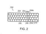
図2は、発明の一つ以上の実施形態による電池モジュール202における電池セル204の配置を示す平面図である。示されるように、セル204は、隣接するセルの中心(例えば中心208a、208b、208c)が、正三角形(例えば三角形210)を形成するように、重ねられた方法で配置される。このようにして、電池セル間の空間206は、最小化される。この重ねられた構成を用いて、モジュール内の空間の例えば約85%は、電池セルで占められる。
FIG. 2 is a plan view illustrating an arrangement of
図3Aは、発明の一つ以上の実施形態による電池モジュール302の分解組立図である。図3B及び図3Cは、図3Aの部分を拡大した図である。電池モジュール302は、カバー304、電圧及び温度モニター及びバランスプリント回路基板(PCB)306、上部及び下部の高電圧(HV)バスバー308、309、モジュールカバー・シール316a、ヒートシンク・シール316b、電池セル310、セルケース(あるいはハウジング)312、及び液冷式ヒートシンク314を含むことができる。
FIG. 3A is an exploded view of a
電池セル310は、例えば円筒状のリチウムイオンセルになりえる。バスバー308は、一つ以上の導電物質を含むことができる。セルケース312は、プラスチック(例えばポリプロピレン、熱伝導性のポリテトラフルオロエチレン(PTFE))あるいはいずれかの適当な材料で作製可能である。シール316a、316bは、いずれかの適当な非導電性ゴム材料から作製可能である。
The
組み立ての間、電池セル310は、セルケース312の内部に設けられ、それは、上述したように、重ねられた配置においてセル310を保持可能なスロットを有する。セルケース312の高さは、セル310の高さとほぼ同じであり、よって、モジュール302を組み立てるために異なる高さのセルが用いられる場合、異なる高さのセルケースが使用可能である。上述した電圧の柔軟性に加えて、セル310の高さ及びセルケース312の高さが同じになるように調節することにより、種々の長さのセルに対応して設計可能である。よって、同じ設計で複数の電圧とともにアンペア時容量を可能にする。バスバー308、309は、それぞれシール316a、316bの開口内に嵌め合わすことができ、その結果、それらは互いに接触することが妨げられ、電気的に絶縁される。バスバー308、309は、多くのセル310の、正及び負極の端子(例えば318)に電気的に連結される。
During assembly, the
PCB306は、電圧をモニターしバランスし、かつ電池モジュール302の温度をモニターするのに使用可能であり、カバー304によって保護される。例示的な実施形態において、モジュール302は、コスト、機械的な複雑さ、電子制御の複雑さ、及びソフトウェア制御の複雑さを減じるように、単一の電子制御PCB306を有する。図3Aに示すように、PCB306は、4つの上部バスバー308の上方で、モジュールの上部カバー304の下方に位置し、プラスチックでモールド可能である。
The
実施形態において、PCB306は、モジュール302の全長に延在しないが、セルのモニタリング及びバランシングの電子制御機能に必要な電子デバイスを装着するのに十分な表面積を提供する。図3AのPCBには穴部があり、それは以下に述べるモジュール構造ネジ又は締付ボルト354を収容するために非メッキであってもよい。PCB306は、上部バスバー308へ直接取り付け可能なバスバー・サーミスターを収容するポート307を有する。PCB306は、ホスト電子制御モジュールと接続するためのケーブルを含んでいる。
In an embodiment, the
例えば図7に示すように、追加のバスバー・サーミスター313は、PCB306の外形と交差しない上部バスバー308へ取り付け可能である。サーミスター313のセンサは、端子の内側に接合され、PCB上で隣接する銅パッドにはんだ付けされる柔軟なリード線(不図示)を有する。同じ構成が他の3つのサーミスターに用いられる。
For example, as shown in FIG. 7, the additional
以下により詳しく説明するように、バスバー308、309は、2つの金属であってもよい。図3Aの実施形態は、穴部へ押し込まれ上方へ突出する外面にネジを切ったスタッド311を有する3つの下部2金属バスバー309を含んでいる。上部バスバーは、正極のアルミニウムの上部バスバー308a、負極の銅の上部バスバー308b、及び、穴部へ押し込まれ上方へ突出する内面にネジを切ったスタッド313を有する2つの上部2金属バスバー308c、308dを含むことができる。
As will be described in more detail below, the bus bars 308, 309 may be two metals. The embodiment of FIG. 3A includes three lower two-
いくつかの実施形態において、モジュール302の2つの対向端部での上部バスバー308a、308bは、それぞれ、セルケーシング312の外側部分に沿って延在するように曲げることができる拡張タブ324を有することができる。拡張タブ324においては、図17から図20に関して説明されるように、複数の電池モジュールを電気的に接続する一若しくは複数の穴部があってもよい。例示的な実施形態において、カバー304は、セルケーシング312に対して拡張タブ324を覆い保持可能な側板319を含んでいる。支持エレメント325は、拡張タブ324を支持するため拡張タブ324の後ろに用いられてもよい。さらに以下で説明する位置決めバー348は、セル310を回転式に位置決めするのを支援するために使用可能である。電圧感知ロッド350は、電圧をモニターし検出するために底部バスバー309からプリント回路基板306に延在する。例えば、電圧感知ロッド350は、各端にて内ネジでレンチ・フラットを有する固い銅の電圧感知ロッド350の形をしているかもしれない。ロッド350は、3つの下部2金属バスバー309とPCB306との間で電気的接続がなされるように、上方へ延在する。結合ネジあるいはボルト354が電池モジュールを通って延在し、ベース355に固定される。
In some embodiments, the
図4Aから図4Dに示されるように、ヒートシンク314は、液冷式でもよく、成型プラスチックでもよいベース250を有する部分組立品、液体を輸送する非同一外形のチューブ254、チューブ254の端にろう付けされあるいは取り付けられるマニホールド、液体輸送フィッティング260,262、成型プラスチック・カバー264、モジュールの環境保護を改善する弾性の周辺シール316b、及び、熱伝導板272を備えることができる。シール316bもまた、図3Aに示され、シール316aに類似している。
As shown in FIGS. 4A-4D, the
熱伝導板272は、特別の熱伝導性の電気的に絶縁されたプラスチック材料から作製可能である。この板は、ヒートシンクのカバー264におけるポートに接着剤で接合可能である。この構成が用いられる場合、効率的な熱伝導を確保するために、図3Aに示すように、調合された熱界面グリースが板272とモジュールの下部バスバー309との間に配置可能である。
The heat
熱伝導板272もまた熱伝導性の導電性のアルミニウム材料から作製可能である。板272は、ヒートシンクのカバー264におけるポートへ接着剤で接合することができる。この構成が用いられる場合、効率的な熱伝導及び電気的絶縁を確保するために、打ち抜きで弾性の熱界面パッドが板272とモジュールの下部2金属バスバー309との間で用いることができる。
The heat
セルにそれほど厳しい要求を必要としないいくつかの応用例では、液体の代わりに空気が使用可能である。ヒートシンク314は、パッケージのコンパクト化のため、モジュールの全長内で重ね合わせることができる。別の実施形態では、ヒートシンク314は、専用の空気熱交換器と取り替えることができる。電池モジュール内で効率的な液体冷却システムを用いて、電池セル及びそれらの端子の環境暴露が低減される。モジュール内で、電池セルの電力端子は、腐食から電圧電極を保護してIP67規格により環境的にシール可能である。
In some applications that do not require very stringent demands on the cell, air can be used instead of liquid. The
図5Aは、図3Aにおけるバスバー308、309の異なる型を図示する。発明の例示的な実施形態によって達成された特徴は、端子を包囲するエレメントとの不要な接触を避けるように、端子の周辺の外側表面への方向にレーザーを適用することにより、バスバーに電池セルの端子を効果的にレーザー溶接可能であることである。そのようにしなければ、そのような接触が起こるかもしれず、レーザーは、よりセルの軸方向つまり端子の方へ下方へ向けられる。図5aで示すように、バスバー628は、電池セル310の端子632の上方に配置され、端子632に対応した輪郭を有する。輪郭は、端子632の周囲に沿って延在する、例えば第1及び第2の側面640、644を有する三角形又は部分的にひし形形状の突起636を備えることができる。端子632がバスバー628の形状に一致するように配向されるので、この配置は、効果的な溶接作業を可能にする。溶接は、端子632とバスバー628との間に電気的接続を生成する。
FIG. 5A illustrates different types of
したがって、溶接は容易に行われ、増加した溶接長さにより構造的完全性を有する。電池モジュールの部品に損傷をもたらすかもしれない、電池セル310の軸方向に沿ってレーザーを向ける代わりに、セルケーシング312の側面から効率的にレーザー溶接を適用可能にしながら、他の適当な形状も、端子632に適切な電気的接続を提供する突起636に用いることもできる。電池セル310の群は、少なくとも第1及び第2の列を備えることができ、端子632は、複数の角を有する周縁形状を有する。例示的な実施形態において、第1列の端子632の角の一つは、第2列から離れて向けられ、第2列における端子632の角の一つは、第1列から離れて向けられる。
Therefore, welding is easy and has structural integrity due to the increased weld length. Instead of directing the laser along the axial direction of the
組み立ての間、溶接648は、突起636の第1及び第2の側面640、644に沿った方向に適用される。バスバー628の形状は、各バスバーに要する材料量を減じながら、電池セル310の複数列のカバーを提供する。さらに図5bを参照して、電池が過熱した場合にガスを放出するために、通気孔652をセル310に設けることができる。バスバー628の下に通気孔を設置することは望ましいかもしれない。通気孔652は、ガスを放出するためにあり、電池セル310の一若しくは両端部で使用可能である。例えば、セル310が過熱した場合、通気孔652は除去された熱いガスを放出する。突起636に対して端子632を特定の配列にすることにより、通気孔は、突起636に対して例えばセル310に目印を整列することで、バスバー628の下の適切な位置に回転して位置決めすることができる。前の実施形態に類似して、対向端部でのバスバー628は、それぞれ、セルケース312の側面に沿って曲がっている拡張タブ656を有することができる。他の電池モジュールと電気的接続をなすために、穴部660を拡張タブ656に設けることができる。
During assembly, the
図5Bに示されるように、端子シール649が端子632の周囲に設けられる。バスバー628が端子632へ例えば溶接されて連結される場合、端子シール649は損傷を受けないことが重要である。発明の態様にしたがい、バスバー628は、端子シール649への損傷の機会を減じながら、端子632にレーザー溶接されるように構成される。このことは、外側を端子の周面650に配置することによりある程度実行され、周面650の方へ向けられる溶接レーザーによりそれらが接近しやすい。例えば、レーザー・ビームは、セル310の軸の方向に垂直あるいはほぼ垂直な方向に向けることができる。
As shown in FIG. 5B, a
図5C及び図5Dは、セル310の長手方向にほぼ垂直な方法でセルの端子領域になされる溶接を図示している。発明の例示的な態様にしたがい、レーザー溶接がセル310の軸方向に適用される場合に別の方法で損傷されるかもしれない端子シール649への損傷を減じあるいは防ぎながら、レーザー・ビーム670は、バスバー設計のため、バスバー628の突起636と端子632との間の接触面積に影響を与え、効果的な溶接を提供する。レーザー・ビーム670は、端子632の第1及び第2の側面640、644の方向に突起636及び端子632に沿って移動するだろう。
FIGS. 5C and 5D illustrate a weld made to the terminal region of the cell in a manner that is substantially perpendicular to the longitudinal direction of the
図6及び図7は、位置決めバー690を用いることにより所定の角度へクロックされた(clocked)あるいは回転して位置決めされたセル310のアレイを図示している。位置決めバー690は、図5bに示されるセル通気孔652がバスバー628の下に配置されることを確保する方法で回転式にセル310の位置決めを支援するために使用可能である。セル310がどのように位置決めされるかにかかわらず、いくつかの実施形態では、熱いガスが電池モジュールのカバーに達するのを防ぐことを助けるため、バスバー628の下に通気孔652を設置することは望ましく、そうでなければ損傷を引き起こすかもしれない。
FIGS. 6 and 7 illustrate an array of
電池セル310は、セルケース312の内側に設けられるとき同じ配向にする必要はない。図8は、電池モジュール402の斜視図であり、ここではモジュール内のいくつかのセルは、モジュール内の他のセルと反対方向に配置される。例えば、モジュール402の左手側のセル410aは、上方へ面するそれらの正極電力端子を有することができ、一方、モジュール402の右手側のセル410bは、下方へ面するそれらの正極電力端子を有することができる。図9は、電池モジュール402の対応する底部を図示する。よって、別の様式で配置された電池セルを含む電池モジュールを設けることが可能である。例えば、あるセルは、上方へ面するそれらの負極電力端子を有することができ、一方、他のセルは、下方へ面するそれらの負極電力端子を有する。従って、ここで述べられるもののようなバスバーは、セルの正極電力端子をセルの負極電力端子と接続することができる。従って、あるセル群は並列に接続されているが、セル群は、また、直列に接続することもできる。
The
図10aは、発明の一若しくは複数の実施形態による電池モジュール502の底面図であり、そのモジュール502は、2列の電池セル510及び一連のバスバー508を有する。示されるように、バスバー508は、電池セル510の両方の列をカバーする幅を有することができる。冷却液入口/出口320を有するヒートシンク314も示されている。
FIG. 10 a is a bottom view of a
図10bは、図10aの一部の拡大図である。図示されるように、3つの隣接した電池セル内に囲まれて、空間504が存在する。例示的な実施形態によれば、冷却装置又は流体に連通する冷却水路は、空間504内に配置することができる。冷却水路は、セルの温度を下げるために用いることができる。
FIG. 10b is an enlarged view of a part of FIG. 10a. As shown, there is a
図11は、発明の一つ以上の実施形態による電池モジュール602の平面図である。モジュール602は、2列の電池セル610及び一連のバスバー608を持っている。バスバー608は、各々、単列における電池セルをカバーする幅を持っている。
FIG. 11 is a plan view of a
いくつかの実施形態において、電池モジュールは、異なる材料から作製された部分を有するバスバーを有することができる。例えば、図12及び図13aに示されるように、バスバー708、712は、アルミニウムで作製された第1部分708a、712a、及び銅から作製された第2部分708b、712bを有することができる。セル710aの正極端子がアルミニウムから作られる場合、これらの端子は、電気的接続を形成するためにアルミニウム部分712aと適切に溶接することができる。同様に、セル710bの負極端子が銅又はニッケル被覆された鋼材から作られる場合、これらの負極端子は、電気的接続を形成するために銅部分712bと容易に溶接することができる。それ故に、2つの金属のバスバーは、2つの異なった金属から作られた電力端子とバスバーとの接続を容易に行うことができる。2つの金属のバスバーは、異なった材料を連結するために摩擦溶接720で形成可能である。
In some embodiments, the battery module can have a bus bar having portions made from different materials. For example, as shown in FIGS. 12 and 13a, the bus bars 708, 712 can have
図13b及び図13cに示されるように、上部バスバー308及び下部バスバー309は、それらに直接結合されるヒューズを有することができる。上部バスバー308及び下部バスバー309の各々は、この構成を有することができる。このヒューズは、精密な打ち抜き穴及び/又はスロット777のアレイであり、ジッパー・ヒューズを形成する。バスバーにヒューズを組み入れることは、モジュールの安全能力を向上させるために、頑丈で、コンパクトで、コストに効果的なアプローチである。重大な自動車衝突で可能性のある最悪ケースの故障モードに関して、ヒューズは、バスバーから過負荷の状態で、セルと機械的に切断され電気的に分離される。モジュールにおける隣接するセルあるいは潜在的に全てのセルで連鎖故障モードを防ぐ特定の時間内でそれが動作するように、実験及び分析は、ジッパー・ヒューズの最適な配置を明らかにする。
As shown in FIGS. 13b and 13c, the
電池セル及びバスバーの異なる構成を用いることによって、一定の合計エネルギーを有する電池モジュールは、異なる出力電圧を提供することができる。図14A、図14B、及び図14Cは、この概念の実施例を図示する。図14A、図14B、及び図14Cの各々は、36個の電池セルを有する電池モジュールの平面図及び底面図を含み、よって、図14A、図14B、及び図14Cにおける3つの電池モジュールの合計エネルギーは、一定である。図14Aにおいて、36個のセルは、6群のセルにグループ化され(例えば群802a、802b)、ここでは、各群におけるセルは並列に接続され、6つの群は直列に接続される。したがって、図14Aで図示される電池モジュールによって提供される電圧は、個々の電池セルの電圧の6倍である。この構成は、6S6P構成と呼ばれ、バスバーのユニークな配置により容易になる。
By using different configurations of battery cells and bus bars, battery modules with constant total energy can provide different output voltages. 14A, 14B, and 14C illustrate an example of this concept. Each of FIGS. 14A, 14B, and 14C includes a plan view and a bottom view of a battery module having 36 battery cells, and thus the total energy of the three battery modules in FIGS. 14A, 14B, and 14C. Is constant. In FIG. 14A, 36 cells are grouped into 6 groups of cells (eg,
図14Bにおいて、36個のセルは、4個のセルの9つの群へグループ化される(例えば群804a、804b)。ここでは、各群におけるセルは、並列に接続され、9つの群は直列に接続される。したがって、図14Bに図示される電池モジュールによって提供される電圧は、個々の電池セルの電圧の9倍である。この構成は、9S4P構成と呼ばれる。図14Cでは、36個のセルは、9個のセルの4つの群へグループ化される(例えば群806a、806b)。ここでは、各群におけるセルは、並列に接続され、4つの群は直列に接続される。したがって、図8Cに図示された電池モジュールによって提供される電圧は、個々の電池セルの電圧の4倍である。この構成は、4S9P構成と呼ばれる。並列に接続されたセルは、偶数個のセルに制限されず、列の数に特別な制限もないことに注意すべきである。
In FIG. 14B, the 36 cells are grouped into 9 groups of 4 cells (eg,
したがって、セル及びバスバーの配向を変更することにより、様々な実施形態による電池モジュールは、異なる出力電圧を提供するように柔軟に構成することができる。36のA123 32157 HD電池セルを使用し、図14A、図14B、及び図14Cに関して記述された3つの異なる構成の動作は、以下の表Iに記載されている。 Thus, by changing the orientation of the cells and bus bars, the battery modules according to various embodiments can be flexibly configured to provide different output voltages. The operation of the three different configurations described with respect to FIGS. 14A, 14B, and 14C using 36 A123 32157 HD battery cells is described in Table I below.

図3Aに関して記述されるように、例えば、いくつかの実施形態において、電池モジュール302は、拡張タブ324を有するバスバーを用いることができる。図15Aは、例示的な電池モジュール302の右上角を示す斜視図である。モジュール302は、電池セル310の上端上のバスバー308bを有する。バスバー308bは、バスバーの面328から下方へ曲げられた拡張タブ324を有し、タブ324の近位端だけが図15Aにおいて可視であるように、セルケース312の制限された開口へ拡張タブが差し込まれる。図15Bは、電池モジュール302の斜視図である。図15Bにおいて、拡張タブ324の遠位端の一部を可視とする開口902がセルケース302にある。拡張タブ324の遠位端は、穴部又は開口326を有し、それは、拡張タブ324を通りボルト(図示せず)が差し込まれるのを可能にし、タブ324との電気的接続を図ることを可能にする。ボルトは、ケース312に固定されたナットと結合可能である。ケース312において拡張タブ324を設けることによって、それは、適所に回転式に保持され、その結果、ボルトの回転の間、拡張タブ324に加えられた力は、ケース312に吸収され、モジュール302の他の部分に作用する偶発的な応力を減じるように、上記他の部分に作用しない。複数のモジュールが電池を形成するために、ともにグループ化され整列される場合、ボルトは、1モジュールの押し出しにおいて拡張タブを通過し、電力端子に機械的トルクを及ぼさずに、他のモジュールの拡張タブと電気的接続を行うことができる。電気的接続を行うため拡張タブを用いる別の利点は、モジュールカバーの周囲のまわりで電池カバーを密閉することができることであり、それにより、カバーにおいて複雑なシール構成を回避できる。
As described with respect to FIG. 3A, for example, in some embodiments, the
図16Aは、ともに連結された複数の電池モジュール1002を示す斜視図である。この例示的な実施形態において、各電池モジュールは、所望の構成に依存して電池セルのより多くの列のうちの一つを含むことができる。いくつかの実施形態において、電池モジュールは、モジュールにおけるセルケース上の連結タブを用いることにより連結することができる。設計目的に依存して異なる数のモジュールを用いることができると認識されるだろう。
FIG. 16A is a perspective view showing a plurality of
図16Bは、図10aのラインA−Aに沿って得られた電池モジュールの一部の断面図である。図16Cは、図16AのラインA−Aに沿って得られた隣接したモジュール1010に連結された電池モジュール1008の断面図である。示されるように、モジュール1008は、モジュール1010のセルケースにおけるスロット1012と連結可能なセルケースから延在するタブ1004を有する。同様に、モジュール1008は、モジュール1010のセルケースのタブ1014とロックすることができるスロット1006を有する。図16Dは、連結機構を用いてともに連結された2つの電池モジュール1008、1010を示す図16aのラインA−Aに沿って得られた断面図である。電池モジュール1008、1010は、モジュール1008、1010、1012及び1014の遠位端1016、1018でスロット及びタブを用いて、隣接したモジュール1012、1014に連結される。
16B is a cross-sectional view of a portion of the battery module obtained along line AA in FIG. 10a. FIG. 16C is a cross-sectional view of
図17及び図18は、連結された関係において複数の組み立てられたセルモジュール1050、1054などを図示する。セルモジュール1050、1054は、接続治具1058によって電気的に連結される。図17の実施形態において、セルモジュール1050、1054は、セルモジュール1050の負極端がセルモジュール1054の正極端に接続されるように、直列に接続される。2つのモジュールが並列に接続されるように、一つのモジュールの正極端子は、別のモジュールの正極端子と電気的に接続可能である(及び負極が負極と)。あるいは、2つのモジュールが直列に接続されるように、一つのモジュールの正極端子は、別のモジュールの負極端子と電気的に接続可能である。モジュールを重ねる能力は、複数モジュール構成を作るために有効で効率的な方法を提供する。
17 and 18 illustrate a plurality of assembled
接続治具1058は、セルモジュール間の電気的接続を行う導電性板1062あるいは他の適当なコネクターを備えることができる。図17の例示的な実施形態は、下部のバスバーにおける穴部1067、1068と結合する締結ボルト1066を利用するような接続治具1058を図示する。接続治具1058は、この設計に限定されず、適切な電気的接続を提供する他の構成の形態をとってもよいことが認識されるだろう。隣接するセルモジュール間の電気的接続を電気的に分離し保護するために、プラスチック・カバーのような絶縁カバー1070は、接続治具1058の上方に配置可能である。図19は、装着されたカバー1070を有する連結されたセルモジュール1074のアレイを図示する。図20は、前述のタブ及びスロット連結構成を用いてともに連結された、複数のセルモジュール1078の平面図である。締付ボルト1082の上端部は、セルモジュール及び冷却液体の入口及び出口1090、1094のベース部1086とともに、図17から図20において可視である。
The
上述したように、いくつかの例示的な実施形態において、2つの金属のバスバーは、好ましくは、両極の電力端子と電気的接続を行うために使用可能であるが、必ずしもそうではない。2つの金属のバスバーは、例えば、両方の金属と溶接可能な中間材料を同一に扱うことで製造することができる。一例として、アルミニウムと銅の2つの金属のバスバー用の中間材料として、銀が使用可能である。2つの金属のバスバーを作る別の方法は、異種金属をともに接合するようにクラッディングによるものであり、例えば、ダイを通して2つの金属を押し出すことにより、あるいは高圧下で金属箔を押圧することによる。さらに、別の例示的なアプローチは、当業者により理解されるように、摩擦溶接技術を用いることである。 As noted above, in some exemplary embodiments, a two metal bus bar is preferably usable, although not necessarily, for making electrical connections with bipolar power terminals. Two metal busbars can be manufactured, for example, by treating both metals and weldable intermediates identically. As an example, silver can be used as an intermediate material for two metal bus bars, aluminum and copper. Another way to make two metal busbars is by cladding to join dissimilar metals together, for example by extruding two metals through a die or by pressing a metal foil under high pressure . Yet another exemplary approach is to use friction welding techniques, as will be appreciated by those skilled in the art.
図21は、本発明の様々な実施形態で使用される2つの金属のバスバーを製造するプロセスを図示する図である。最初に、銅部分1104a及びアルミニウム部分1104bを含むチューブ1102は、2つの異なる金属を摩擦溶接により作製される。よって、管部1106は、チューブ1102から切断され、2つの金属のバスバーを提供するようにロールされる。2金属片を製造するための当該技術分野で既知の他の方法が2金属バスバーを製造するために使用可能である。
FIG. 21 is a diagram illustrating a process for manufacturing a two metal bus bar used in various embodiments of the invention. Initially, a
電池セルは、電池セルの一端あるいは両端部で一般的に通気孔(複数可)(ガスを放出するためのバルブ)を有することができる。通気孔は、例えば、セルが過熱したとき、熱い排出されたガスを放出する。温度の低下なしに熱いガスが電池モジュールのカバーに達するならば、それはモジュールを損傷させるかもしれない。本発明の実施形態は、また効率的なセル通気設計を有する電池モジュールを提供する。 A battery cell can generally have a vent hole (s) (a valve for releasing gas) at one or both ends of the battery cell. The vent releases, for example, hot exhausted gas when the cell is overheated. If hot gas reaches the battery module cover without a drop in temperature, it may damage the module. Embodiments of the present invention also provide a battery module having an efficient cell ventilation design.
図22から図26は、セルモジュール1400のバスバーをセル端子にレーザー溶接するために使用される固定具を図示する。セル端子及びバスバーは、上の実施形態に記載されていたものであってもよい。固定具は、位置決めピン1401及びボルト1402でともに留められる4つの主な半組立部品を有する。組み立てられた固定具は、レーザ溶接の間、モジュールのセルケース1404、セル1406及びバスバー1408を位置決めし把持する。一つの実施形態において、固定具は、不可欠のハンドルを介して手動で固定具を反転するため、たった一つの短い休止とともに自動レーザ溶接を可能にする。ボルト1402の使用は、コスト及び複雑さを制限するのに向いている。大量生産に関して、製造時間を縮小するために、類似の固定具は、ボルトよりもむしろ迅速動作機構を使用してもよい。
22 to 26 illustrate a fixture used to laser weld the bus bar of the
第1の主な半組立部品は、硬いランドプレート1410、及び位置決めピン、ボルト、ネジ固定接着剤を介してそのプレートに取り付けられる2つの硬い隙間ブロック1412を有する。ランドプレート1410の材料は、固定具が妥当な労力で手動で移動可能なようにアルミニウムでもよい。ランドプレート1410は、モジュールのセルケース1404を設置し把持するために多くの凹状表面を有する。隙間ブロック1412の材料は、モジュール1400に関して、各端部で隣接する上部正極アルミニウムバスバー及び上部負極銅バスバーとの偶発的な電気的短絡の危険を避けるように、ガラス繊維強化プラスチックであってもよい。隙間ブロック1412は、固定具の他の主な3つの半組立部品を保持する位置決めピン及びボルトと結合するため、複数の平面及びネジ穴を有する。
The first major subassembly has a
第2の主な半組立部品は、硬い押圧板で、これを保持するためのピン及びボルトを有し、アルミニウムであってもよい、押圧板1416を有する。押圧板1416は、隙間ブロックの位置決めピンと結合する平面穴のパターンを除いてランドプレート1410に類似している。
The second main semi-assembled part is a hard pressure plate with pins and bolts to hold it, and has a
第3の主な半組立部品は、硬いプッシュバーで、これを保持するためのピン及びボルトを有し、ガラス繊維強化プラスチックであってもよい、プッシュバー1418を有する。プッシュバー1418は、また、モジュールの下部の2金属バスバーと接続する精度バスバー位置決めボタン1422を有する。プッシュバー1418は、また、各レーザー溶接経路に関してぴったりはまることを確保するために、セルサイト毎でバスバーを押圧するバネ付勢されたプランジャ1426を有する。
The third major subassembly has a
第4の主な半組立部品は、硬いプッシュバーで、これを保持するためのピン及びボルトを有し、ガラス繊維強化プラスチックであってもよい、プッシュバー1428を有する。プッシュバー1418に類似して、プッシュバー1428は、モジュールの上部の正極アルミニウムバスバー、上部の負極銅バスバー、及び2つの上部の2金属バスバーと接続する精度バスバー位置決めボタンを有する。プッシュバー1428は、また、各レーザー溶接経路に関してぴったりはまることを確保するために、セルサイト毎でバスバーを押圧するバネ付勢されたプランジャを有する。完全なアセンブリーが図26に示され、これは溶接レーザーの入射用の開口1432を含んでいる。
The fourth main subassembly has a
セルは、全体の電池システム容量を増加させるために、しばしば電池モジュール内で並列にて電気的に接続される。いくつかの電池システムの応用例は、成功した競争、及び内部セル短絡となる欠陥をシミュレートする酷使テストの合格を必要とする。セル爪で刺すことによるシミュレートされた短絡は、迅速なセル放電の間、セル内でセル温度増加となる。並列のセルは、刺されたセルによって放電される必要のある増加したエネルギーのため、さらに温度が上がる。並列セルからのエネルギーが刺されたセルに入るのを防ぐために、この状態の間、電流を遮断するため、ヒューズが並列セルの各々に直列に設置可能である。 Cells are often electrically connected in parallel within battery modules to increase the overall battery system capacity. Some battery system applications require successful competition and passing an abuse test that simulates a defect that results in an internal cell short circuit. A simulated short circuit due to cell nail penetration results in an increase in cell temperature within the cell during rapid cell discharge. The parallel cells are heated further due to the increased energy that needs to be discharged by the stabbed cells. To prevent energy from the parallel cells from entering the stabbed cell, a fuse can be placed in series with each of the parallel cells to interrupt the current during this state.
本発明の実施形態は、電池モジュール用の本質的に安全でコンパクトなヒューズを提供する。電池モジュールにおいて、ヒューズは、各セルに適用でき、重ねられたセル間の空間に位置することができる。あるいはヒューズは、バスバーに割り込むこともできる。図27Aは、バスバー1302及びヒューズ1304を含む電池モジュールの様々な部品の分解組立図である。図27Bは、バスバー1302及びヒューズ1304aを示す図である。図27Cは、ヒューズ1304a及びセル1308を図示する図である。
Embodiments of the present invention provide an intrinsically safe and compact fuse for battery modules. In a battery module, a fuse can be applied to each cell and can be located in the space between the stacked cells. Alternatively, the fuse can interrupt the bus bar. FIG. 27A is an exploded view of the various parts of the battery module including the
発明の例示的な実施形態によるモジュールパッケージは、セル空間の有効な利用を提供する。円筒状セルを重ねることは、セル間に三角形の空間を生成する。その空間は、重ねられたセルの各々用のヒューズを収容するために使用可能である。プラスチックセルハウジングに封入されたヒューズは、セルヒューズが開いた場合に、電池モジュール内の潜在的可燃性の混合物が点火するのを防ぐのに役立つであろう本質的に安全な環境を提供する。例えば、円筒状セルに関して、ヒューズは、重ねられたセル間の三角形の空間に位置可能である。本質的に安全な溶断方法は、電気的バスバーに割り込ませたヒューズであるかもしれず、モジュール内で火花が潜在的燃焼性のガスに達するのを防ぐように密封した環境内に存在するような方法で密閉されてもよい。密閉されたバスバーは、セル端子への溶接あるいはボルト締めでの接続を許容しながら、溶断部分のみをカバーすることができ、よって、良好な空間利用を有するコンパクト設計を可能にする。 A module package according to an exemplary embodiment of the invention provides efficient utilization of cell space. Overlapping cylindrical cells creates a triangular space between the cells. That space can be used to accommodate a fuse for each of the stacked cells. The fuse enclosed in the plastic cell housing provides an inherently safe environment that will help prevent potentially flammable mixtures in the battery module from igniting when the cell fuse is opened. For example, for a cylindrical cell, the fuse can be located in a triangular space between the stacked cells. An intrinsically safe fusing method may be a fuse interrupted by an electrical busbar, such that it exists in a sealed environment to prevent sparks from reaching potentially flammable gases within the module. It may be sealed with. The sealed bus bar can cover only the fused part while allowing welding or bolting connection to the cell terminals, thus allowing a compact design with good space utilization.
多数の追加の利点あるいは変更は、当該技術における通常の技術を有する者によって実現されるかもしれない。従って、発明は、開示された非制限の実施形態に限定されていないが、添付の請求項の全部の精神及び範囲内にあると解釈されることは意図される。 Numerous additional advantages or modifications may be realized by those having ordinary skill in the art. Accordingly, the invention is not limited to the disclosed non-limiting embodiments, but is intended to be construed within the full spirit and scope of the appended claims.
Claims (15)
セルケーシング内に配置された複数の電池セルであり、その長手方向端部にそれぞれ端子を有し、該端子は上部及び外周側面部分を有する、電池セルと、
一群の電池セル間の電気的接続を提供する少なくとも一つのバスバー・セグメントであり、少なくとも一つのバスバー・セグメントは端子の上部に接触するため各電池セルの上記長手方向端部を横切り延在する、バスバー・セグメントと、
を備え、
端子の外周側面は、端子を少なくとも一つのバスバー・セグメントに溶接するため、レーザーが外周側面の方へ向けられるように少なくとも一つのバスバー・セグメントによって遮られていない、
電池モジュール。 A cell casing;
A plurality of battery cells arranged in a cell casing , each having a terminal at a longitudinal end thereof , the terminal having an upper part and an outer peripheral side part;
At least one bus bar segment provides an electrical connection between a group of battery cells, at least one bus bar segment extends across the longitudinal ends of each battery cell Le for contacting the top of the terminal The busbar segment,
With
The outer peripheral side of the terminal is unobstructed by the at least one bus bar segment so that the laser is directed toward the outer peripheral side to weld the terminal to the at least one bus bar segment;
Battery module.
任意に、上記端子は、正方形の周縁形状を有する、請求項2記載の電池モジュール。 The battery cell group includes at least first and second rows, the terminal has a peripheral shape having a plurality of corners, and one of the terminal corners in the first row is directed away from the second row. , One of the terminal corners in the second row is directed away from the first row,
3. The battery module according to claim 2, wherein the terminal has a square peripheral shape.
任意に、カバーを備え、プリント回路基板は、カバーと複数のバスバー・セグメントとの間で複数のバスバー・セグメントに沿って延在する、請求項3記載の電池モジュール。 A printed circuit board for monitoring at least one of voltage and temperature of the battery module;
4. The battery module according to claim 3, further comprising a cover, wherein the printed circuit board extends along the plurality of bus bar segments between the cover and the plurality of bus bar segments.
任意に、ヒートシンクは、第2のバスバー構成に沿って延在し、冷却液入口及び出口を備える、請求項8記載の電池モジュール。 A heat sink for cooling the second bus bar configuration;
9. The battery module of claim 8, wherein the heat sink optionally extends along the second bus bar configuration and comprises a coolant inlet and an outlet.
電池セルは、隣接した電池セルの中心が正三角形を形成する重ねられた方法で配置され、及び/又は、電池セルは、円筒状のリチウムイオンセルである、請求項1記載の電池モジュール。 Fuse configuration surrounding each battery cell terminal,
The battery module according to claim 1, wherein the battery cells are arranged in an overlapping manner in which the centers of adjacent battery cells form an equilateral triangle, and / or the battery cells are cylindrical lithium ion cells.
アレイ状に複数の電池セルを配置し、ここで複数の電池セルは端子を持つ第1長手方向端部を有し、端子はそれぞれ上部及び外周側面を有し、
端子の上部を横切りバスバーを配置し、それにより端子の外周側面が露出され、
バスバーと端子との間で溶接を確立するように端子の外周側面でレーザーを向けること、
を備えた方法。 A method for manufacturing a battery module comprising:
A plurality of battery cells are arranged in an array, wherein the plurality of battery cells have first longitudinal ends with terminals, each terminal having an upper portion and an outer peripheral side surface,
Place the bus bar across the top of the terminal, so that the outer peripheral side of the terminal is exposed,
Directing the laser on the outer peripheral side of the terminal to establish a weld between the busbar and the terminal,
With a method.
任意に、突起は端子の少なくとも2つの外周側面と整列する第1側面及び第2側面を有し、レーザーは、溶接を確立するために端子の少なくとも2つの外周側面に沿って与えられる、請求項12記載の方法。 The terminal includes at least two outer peripheral surfaces, and the bus bar includes a protrusion that contacts the terminal.
Optionally, the protrusion has a first side and a second side aligned with at least two outer peripheral sides of the terminal, and the laser is provided along at least two outer peripheral sides of the terminal to establish a weld. 12. The method according to 12.
又は、第1セルケーシングにヒートシンクを設けることをさらに備え、ヒートシンクは、電池セルの第2の長手方向端から熱を抜き取る、請求項14記載の方法。 A second cell casing in which a plurality of second battery cells are arranged inside is provided, and the second cell casing is further connected to the first cell casing using a connecting mechanism on a side surface of the first and second cell casings. ,
The method of claim 14 , further comprising providing a heat sink in the first cell casing, wherein the heat sink extracts heat from the second longitudinal end of the battery cell.
Applications Claiming Priority (3)
| Application Number | Priority Date | Filing Date | Title |
|---|---|---|---|
| US4478408P | 2008-04-14 | 2008-04-14 | |
| US61/044,784 | 2008-04-14 | ||
| PCT/US2009/040583 WO2009154855A2 (en) | 2008-04-14 | 2009-04-14 | Flexible voltage nested battery module design |
Publications (3)
| Publication Number | Publication Date |
|---|---|
| JP2011521403A JP2011521403A (en) | 2011-07-21 |
| JP2011521403A5 JP2011521403A5 (en) | 2012-06-07 |
| JP5518046B2 true JP5518046B2 (en) | 2014-06-11 |
Family
ID=41380234
Family Applications (1)
| Application Number | Title | Priority Date | Filing Date |
|---|---|---|---|
| JP2011505152A Active JP5518046B2 (en) | 2008-04-14 | 2009-04-14 | Battery module design that can accommodate and store free voltage |
Country Status (9)
| Country | Link |
|---|---|
| US (1) | US8475954B2 (en) |
| EP (1) | EP2266154B8 (en) |
| JP (1) | JP5518046B2 (en) |
| KR (1) | KR101633943B1 (en) |
| CN (1) | CN102057519B (en) |
| BR (1) | BRPI0911250A2 (en) |
| CA (1) | CA2721548C (en) |
| PL (1) | PL2266154T3 (en) |
| WO (1) | WO2009154855A2 (en) |
Families Citing this family (188)
| Publication number | Priority date | Publication date | Assignee | Title |
|---|---|---|---|---|
| DE102008035169B3 (en) * | 2008-07-28 | 2010-01-21 | Amphenol-Tuchel Electronics Gmbh | Electric conductor for energy storage |
| EP2359423A1 (en) * | 2008-11-17 | 2011-08-24 | ABB Research Ltd. | Arrangement of stationary batteries |
| KR20120049839A (en) * | 2009-07-17 | 2012-05-17 | 파나소닉 주식회사 | Battery module and battery pack using same |
| KR101202542B1 (en) * | 2009-07-17 | 2012-11-20 | 파나소닉 주식회사 | Battery module and battery pack using the same |
| US8841017B2 (en) * | 2009-07-24 | 2014-09-23 | GM Global Technology Operations LLC | Cell tab and interconnect assembly for a battery pack |
| KR101108184B1 (en) * | 2009-12-11 | 2012-02-06 | 삼성에스디아이 주식회사 | Battery Pack |
| KR101360825B1 (en) * | 2009-12-21 | 2014-02-10 | 에스케이이노베이션 주식회사 | Battery Management Apparatus of High Voltage Battery for Hybrid Vehicle |
| TWM382596U (en) * | 2009-12-23 | 2010-06-11 | Amita Technologies Inc Co Ltd | Battery module |
| US9077015B2 (en) * | 2010-02-24 | 2015-07-07 | Panasonic Intellectual Property Management Co., Ltd. | Battery pack |
| US20110223468A1 (en) * | 2010-03-15 | 2011-09-15 | Electronvault, Inc. | Variable Energy System |
| US20110221398A1 (en) * | 2010-03-15 | 2011-09-15 | Electronvault, Inc. | Impedence Balancer |
| US20110223458A1 (en) * | 2010-03-15 | 2011-09-15 | Electronvault, Inc. | Power Cell Array Receiver |
| US8859122B2 (en) * | 2010-03-19 | 2014-10-14 | GM Global Technology Operations LLC | Interconnect device for battery assembly |
| US8403019B2 (en) | 2010-05-24 | 2013-03-26 | Lg Chem, Ltd. | Ultrasonic welding assembly and method of attaching an anvil to a bracket of the assembly |
| KR101201747B1 (en) * | 2010-05-24 | 2012-11-15 | 에스비리모티브 주식회사 | Battery module |
| JP5663962B2 (en) * | 2010-05-31 | 2015-02-04 | ソニー株式会社 | Battery unit |
| KR101136310B1 (en) * | 2010-06-07 | 2012-04-19 | 에스비리모티브 주식회사 | Battery pack |
| US8563159B2 (en) | 2010-08-04 | 2013-10-22 | Bren-Tronics Batteries International, L.L.C. | Structure and method for removing battery cell heat |
| US9005799B2 (en) * | 2010-08-25 | 2015-04-14 | Lg Chem, Ltd. | Battery module and methods for bonding cell terminals of battery cells together |
| KR101386860B1 (en) * | 2010-10-15 | 2014-04-17 | 닛산 지도우샤 가부시키가이샤 | Battery pack |
| JPWO2012053610A1 (en) * | 2010-10-21 | 2014-02-24 | 株式会社キャプテックス | Battery connector, assembled battery module, method of manufacturing battery module, and method of manufacturing battery connector |
| TWI433377B (en) * | 2010-11-29 | 2014-04-01 | Ind Tech Res Inst | Battery set package |
| FR2968460B1 (en) * | 2010-12-06 | 2016-11-25 | Valeo Equip Electr Moteur | ENERGY STORER FLASK |
| CN103260923B (en) | 2010-12-07 | 2016-12-21 | 艾里逊变速箱公司 | Energy storage system for hybrid-power electric vehicle |
| US9034129B2 (en) | 2011-01-13 | 2015-05-19 | Lg Chem, Ltd. | Ultrasonic welding system and method for forming a weld joint utilizing the ultrasonic welding system |
| JP2012160339A (en) * | 2011-01-31 | 2012-08-23 | Sanyo Electric Co Ltd | Battery pack and battery connection method |
| DE102011005222A1 (en) * | 2011-03-08 | 2012-09-13 | Sb Limotive Company Ltd. | A connector for making an electrically conductive connection between at least three terminals of battery cells |
| US8859130B2 (en) * | 2011-03-11 | 2014-10-14 | GM Global Technology Operations LLC | Battery cover for a high voltage automotive battery |
| WO2012142583A2 (en) * | 2011-04-15 | 2012-10-18 | Enerdel, Inc. | Battery terminal system |
| FR2974453B1 (en) * | 2011-04-19 | 2014-02-28 | Valeo Systemes Thermiques | DEVICE FOR THERMALLY MANAGING A BATTERY PACK |
| CN102934314B (en) * | 2011-04-25 | 2015-12-02 | 丰田自动车株式会社 | Power brick |
| WO2012148100A2 (en) | 2011-04-26 | 2012-11-01 | 주식회사 엘지화학 | Bus bar having a novel structure, and battery module including same |
| JP2012234698A (en) * | 2011-04-28 | 2012-11-29 | Toyota Motor Corp | Power storage device |
| KR101201066B1 (en) | 2011-06-14 | 2012-11-14 | 삼성에스디아이 주식회사 | Battery pack |
| US20130164567A1 (en) * | 2011-06-24 | 2013-06-27 | Seektech, Inc. | Modular battery pack apparatus, systems, and methods |
| US8640760B2 (en) | 2011-08-19 | 2014-02-04 | Lg Chem, Ltd. | Ultrasonic welding machine and method of aligning an ultrasonic welding horn relative to an anvil |
| US8695867B2 (en) | 2011-08-31 | 2014-04-15 | Lg Chem, Ltd. | Ultrasonic welding machine and method of assembling the ultrasonic welding machine |
| US8835029B2 (en) * | 2011-10-04 | 2014-09-16 | International Business Machines Corporation | Fuse for three dimensional solid-state battery |
| US8889292B2 (en) * | 2011-10-13 | 2014-11-18 | Samsung Sdi Co., Ltd. | Rechargeable battery |
| WO2013081375A1 (en) | 2011-11-28 | 2013-06-06 | 주식회사 엘지화학 | Battery module and bus bar applied to battery module |
| JP5511778B2 (en) * | 2011-12-16 | 2014-06-04 | 株式会社デンソー | Manufacturing method of heat exchanger, and heat exchanger manufactured by the manufacturing method |
| CN104025337B (en) | 2011-12-19 | 2016-07-06 | 日立汽车系统株式会社 | The Welding Structure of battery, its forming method, secondary monocell and secondary battery module |
| WO2013103244A1 (en) * | 2012-01-03 | 2013-07-11 | 주식회사 엘지화학 | Battery pack and connecting bar applied to same |
| AU2012373356B2 (en) * | 2012-03-12 | 2016-02-25 | Chung Peng Liew | Non-welded battery module |
| US8802249B2 (en) * | 2012-06-13 | 2014-08-12 | Eetrex, Inc. | Cellular fusible link and battery module configuration |
| US8517078B1 (en) | 2012-07-24 | 2013-08-27 | Lg Chem, Ltd. | Ultrasonic welding assembly and method of attaching an anvil to a bracket of the assembly |
| CN104854726B (en) | 2012-10-16 | 2018-09-21 | 安布里公司 | Electrochemical energy storage device and shell |
| US11211641B2 (en) | 2012-10-18 | 2021-12-28 | Ambri Inc. | Electrochemical energy storage devices |
| US9735450B2 (en) | 2012-10-18 | 2017-08-15 | Ambri Inc. | Electrochemical energy storage devices |
| US11721841B2 (en) | 2012-10-18 | 2023-08-08 | Ambri Inc. | Electrochemical energy storage devices |
| US10541451B2 (en) | 2012-10-18 | 2020-01-21 | Ambri Inc. | Electrochemical energy storage devices |
| US9520618B2 (en) | 2013-02-12 | 2016-12-13 | Ambri Inc. | Electrochemical energy storage devices |
| US11387497B2 (en) | 2012-10-18 | 2022-07-12 | Ambri Inc. | Electrochemical energy storage devices |
| US9312522B2 (en) | 2012-10-18 | 2016-04-12 | Ambri Inc. | Electrochemical energy storage devices |
| KR101386167B1 (en) * | 2012-11-27 | 2014-04-18 | 삼성에스디아이 주식회사 | Battery pack |
| JP5672294B2 (en) * | 2012-11-30 | 2015-02-18 | トヨタ自動車株式会社 | Battery pack and vehicle |
| EP2744034B1 (en) * | 2012-12-07 | 2015-02-18 | Obrist Powertrain GmbH | Heat exchanger assembly |
| DE102012111970A1 (en) * | 2012-12-07 | 2014-06-12 | Dr. Ing. H.C. F. Porsche Aktiengesellschaft | Battery assembly and method for cooling a battery |
| EP2744033B1 (en) | 2012-12-07 | 2015-02-18 | Obrist Powertrain GmbH | Battery |
| US8920955B1 (en) * | 2012-12-13 | 2014-12-30 | Atieva, Inc. | Battery module with high thermal conductivity and assembling method thereof |
| WO2014105092A2 (en) * | 2012-12-24 | 2014-07-03 | Tutunaru Catalin | Advances in electric car technology |
| DE102013201129A1 (en) * | 2013-01-24 | 2014-07-24 | Robert Bosch Gmbh | Battery module with a thermal element |
| US20140212695A1 (en) * | 2013-01-30 | 2014-07-31 | Tesla Motors, Inc. | Flexible printed circuit as high voltage interconnect in battery modules |
| US9899643B2 (en) * | 2013-02-27 | 2018-02-20 | Ioxus, Inc. | Energy storage device assembly |
| JP6433029B2 (en) * | 2013-02-27 | 2018-12-05 | アイオクサス, インコーポレイテッドIoxus,Inc. | Energy storage device assembly |
| US9738976B2 (en) | 2013-02-27 | 2017-08-22 | Ioxus, Inc. | Energy storage device assembly |
| US10270139B1 (en) | 2013-03-14 | 2019-04-23 | Ambri Inc. | Systems and methods for recycling electrochemical energy storage devices |
| JP2014191968A (en) * | 2013-03-27 | 2014-10-06 | Toyoda Gosei Co Ltd | Battery device |
| DE102013209391A1 (en) * | 2013-05-22 | 2014-11-27 | Robert Bosch Gmbh | Battery cell assembly |
| US9502737B2 (en) | 2013-05-23 | 2016-11-22 | Ambri Inc. | Voltage-enhanced energy storage devices |
| US9892868B2 (en) | 2013-06-21 | 2018-02-13 | Ioxus, Inc. | Energy storage device assembly |
| US9537125B2 (en) * | 2013-06-27 | 2017-01-03 | Samsung Sdi Co., Ltd. | Battery module |
| KR101749509B1 (en) | 2013-09-13 | 2017-06-21 | 삼성에스디아이 주식회사 | Battery pack having welding portion |
| KR102073193B1 (en) * | 2013-09-23 | 2020-02-04 | 삼성에스디아이 주식회사 | Battery Pack |
| FR3011390B1 (en) * | 2013-09-30 | 2017-02-17 | Thierry Claudel | ELECTRIC BATTERY MODULE |
| DK3058605T3 (en) | 2013-10-16 | 2024-03-04 | Ambri Inc | SEALS FOR DEVICES OF REACTIVE HIGH TEMPERATURE MATERIAL |
| JP6492668B2 (en) * | 2014-01-23 | 2019-04-03 | 株式会社村田製作所 | Power storage device, power storage system, electronic device, electric vehicle, and power system |
| DE102014002165B3 (en) * | 2014-02-19 | 2015-01-22 | Lisa Dräxlmaier GmbH | Method for fixing round cells by means of compressed cell fixation and cell block |
| DE102014206646A1 (en) | 2014-04-07 | 2015-10-08 | Robert Bosch Gmbh | Energy storage unit, in particular battery module, and energy storage system with a plurality of energy storage units |
| JP6394063B2 (en) | 2014-05-22 | 2018-09-26 | 株式会社村田製作所 | Battery pack, power storage device, power storage system, electronic device, electric vehicle, and power system |
| FR3022402B1 (en) * | 2014-06-13 | 2021-05-28 | Ifp Energies Now | MODULAR ELECTRIC BATTERY INCLUDING A THERMAL PROTECTION AND REGULATION DEVICE |
| JP6250885B2 (en) * | 2014-07-08 | 2017-12-20 | 株式会社キャプテックス | Battery pack |
| US9508966B2 (en) * | 2014-07-30 | 2016-11-29 | Ford Global Technologies, Llc | Array frame design for electrified vehicle battery arrays |
| US10211443B2 (en) | 2014-09-10 | 2019-02-19 | Cellink Corporation | Battery interconnects |
| US9147875B1 (en) | 2014-09-10 | 2015-09-29 | Cellink Corporation | Interconnect for battery packs |
| US9520587B2 (en) | 2014-09-30 | 2016-12-13 | Johnson Controls Technology Company | Bus bar assembly carrier |
| DE102014014850A1 (en) | 2014-10-07 | 2016-04-07 | Audi Ag | Energy storage arrangement, motor vehicle comprising such an energy storage device and method for their preparation |
| US9437860B2 (en) | 2014-11-20 | 2016-09-06 | Ford Global Technologies, Llc | Traction battery assembly having snap-in bus bar module |
| US20160172653A1 (en) * | 2014-12-15 | 2016-06-16 | Nec Energy Solutions, Inc. | Battery containment |
| US10673050B2 (en) * | 2015-01-05 | 2020-06-02 | Cps Technology Holdings Llc | Battery module terminal system and method |
| US9779887B2 (en) * | 2015-01-15 | 2017-10-03 | Ioxus, Inc. | Apparatus for enclosing energy storage devices |
| EP3254308B1 (en) | 2015-02-03 | 2022-04-13 | CelLink Corporation | Systems for combined thermal and electrical energy transfer |
| CA2954151C (en) * | 2015-02-09 | 2017-09-26 | Acculogic Corporation | Method and device for testing the connections of batteries |
| US10181800B1 (en) | 2015-03-02 | 2019-01-15 | Ambri Inc. | Power conversion systems for energy storage devices |
| WO2016141354A2 (en) | 2015-03-05 | 2016-09-09 | Ambri Inc. | Ceramic materials and seals for high temperature reactive material devices |
| US9893385B1 (en) | 2015-04-23 | 2018-02-13 | Ambri Inc. | Battery management systems for energy storage devices |
| USD763193S1 (en) | 2015-06-02 | 2016-08-09 | Johnson Controls Technology Controls | Bus bar carrier for lithium ion battery module |
| US11108100B2 (en) | 2015-06-30 | 2021-08-31 | Faraday & Future Inc. | Battery module for vehicle energy-storage systems |
| US9995535B2 (en) | 2015-06-30 | 2018-06-12 | Faraday&Future Inc. | Heat pipe for vehicle energy-storage systems |
| US9692095B2 (en) * | 2015-06-30 | 2017-06-27 | Faraday&Future Inc. | Fully-submerged battery cells for vehicle energy-storage systems |
| US9692096B2 (en) * | 2015-06-30 | 2017-06-27 | Faraday&Future Inc. | Partially-submerged battery cells for vehicle energy-storage systems |
| US10505163B2 (en) | 2015-06-30 | 2019-12-10 | Faraday & Future Inc. | Heat exchanger for vehicle energy-storage systems |
| US20170005303A1 (en) | 2015-06-30 | 2017-01-05 | Faraday&Future Inc. | Vehicle Energy-Storage System |
| US11258104B2 (en) | 2015-06-30 | 2022-02-22 | Faraday & Future Inc. | Vehicle energy-storage systems |
| US10826042B2 (en) * | 2015-06-30 | 2020-11-03 | Faraday & Future Inc. | Current carrier for vehicle energy-storage systems |
| US10407004B2 (en) * | 2015-06-30 | 2019-09-10 | Faraday & Future Inc. | Solid state switch for vehicle energy-storage systems |
| US9793530B2 (en) * | 2015-07-17 | 2017-10-17 | Atieva, Inc. | Battery assembly with linear bus bar configuration |
| CN105070966A (en) * | 2015-08-17 | 2015-11-18 | 苏州安靠电源有限公司 | Battery pack signal sampling sheet |
| KR102476340B1 (en) * | 2015-11-09 | 2022-12-09 | 삼성에스디아이 주식회사 | Battery module |
| KR102497113B1 (en) * | 2015-11-19 | 2023-02-07 | 삼성에스디아이 주식회사 | Battery pack |
| US10319494B2 (en) * | 2016-02-05 | 2019-06-11 | Ematrix Energy Systems, Inc. | Multi-functional busbar with interstitial passages |
| EP3220444A1 (en) * | 2016-03-14 | 2017-09-20 | Nordfels GmbH | Battery |
| US10784545B2 (en) * | 2016-03-25 | 2020-09-22 | Xing Power Inc. | Submerged cell modular battery system |
| WO2017163850A1 (en) * | 2016-03-25 | 2017-09-28 | 三洋電機株式会社 | Power source device |
| KR20170134270A (en) * | 2016-05-27 | 2017-12-06 | 신흥에스이씨주식회사 | Battery pack for electric vehicle with excellent vibration-resistance |
| TR201610197A2 (en) * | 2016-07-22 | 2018-02-21 | Temsa Ulasim Araclari Sanayi Ve Ticaret Anonim Sirketi | A CHARGEABLE BATTERY MODULE |
| DE102016115804A1 (en) * | 2016-08-25 | 2018-03-01 | HELLA GmbH & Co. KGaA | Cell monitoring module for a battery cell monitoring unit and battery cell monitoring unit |
| KR102164002B1 (en) | 2016-09-02 | 2020-10-12 | 삼성에스디아이 주식회사 | Band assembly |
| US10396410B2 (en) * | 2016-09-07 | 2019-08-27 | Thunder Power New Energy Vehicle Development Company Limited | Battery system housing with internal busbar |
| US11929466B2 (en) | 2016-09-07 | 2024-03-12 | Ambri Inc. | Electrochemical energy storage devices |
| US10700335B2 (en) * | 2016-09-07 | 2020-06-30 | Thunder Power New Energy Vehicle Development Company Limited | Battery system housing with internal busbar |
| US20180069212A1 (en) * | 2016-09-07 | 2018-03-08 | Thunder Power New Energy Vehicle Development Company Limited | Battery system housing with bonded rib fixation |
| CN117638425A (en) | 2016-09-22 | 2024-03-01 | 苹果公司 | Current collector for stacked cell design |
| CN106328847A (en) * | 2016-09-27 | 2017-01-11 | 深圳市沃特玛电池有限公司 | Battery module structure |
| TWI637547B (en) | 2016-11-08 | 2018-10-01 | 磐石電池股份有限公司 | Battery parallel device with equal resistance charge and discharge path |
| EP3346523B1 (en) | 2017-01-06 | 2019-03-27 | Samsung SDI Co., Ltd. | Battery system with a cell connecting unit |
| EP3346524A1 (en) * | 2017-01-09 | 2018-07-11 | Samsung SDI Co., Ltd | Battery module with thermocouple unit |
| WO2018134982A1 (en) * | 2017-01-20 | 2018-07-26 | 日産自動車株式会社 | Assembled battery, bus bar holder used for assembled battery, and method for manufacturing assembled battery |
| US10041163B1 (en) | 2017-02-03 | 2018-08-07 | Ge-Hitachi Nuclear Energy Americas Llc | Plasma spray coating for sealing a defect area in a workpiece |
| EP3607603A4 (en) | 2017-04-07 | 2021-01-13 | Ambri Inc. | Molten salt battery with solid metal cathode |
| CN108735927A (en) * | 2017-04-21 | 2018-11-02 | 上海蔚来汽车有限公司 | GU Generic Unit and battery modules |
| WO2018195372A1 (en) | 2017-04-21 | 2018-10-25 | Cougeller Research Llc | Battery cell with electrolyte diffusion material |
| WO2018213601A2 (en) | 2017-05-19 | 2018-11-22 | Cougeller Research Llc | Rechargeable battery with anion conducting polymer |
| CN110832694B (en) | 2017-07-24 | 2023-12-29 | 松下新能源株式会社 | Battery pack and method for manufacturing same |
| DE102017213470A1 (en) | 2017-08-03 | 2019-02-07 | Bayerische Motoren Werke Aktiengesellschaft | Battery module and battery module stack for a motor vehicle |
| US11862801B1 (en) | 2017-09-14 | 2024-01-02 | Apple Inc. | Metallized current collector for stacked battery |
| KR102415121B1 (en) * | 2017-09-22 | 2022-06-30 | 삼성에스디아이 주식회사 | Battery pack |
| US11043703B1 (en) | 2017-09-28 | 2021-06-22 | Apple Inc. | Stacked battery components and configurations |
| KR102444124B1 (en) * | 2017-10-16 | 2022-09-16 | 주식회사 엘지에너지솔루션 | Battery module and battery pack having the same |
| TWI642221B (en) * | 2017-12-21 | 2018-11-21 | 車王電子股份有限公司 | Battery connecting piece and battery connecting module |
| KR102288405B1 (en) * | 2017-12-26 | 2021-08-09 | 주식회사 엘지에너지솔루션 | Cylindrical battery cell assembly improved in space utilization and safety and battery module including the same |
| CN108111138B (en) * | 2017-12-27 | 2021-06-15 | 安徽华东光电技术研究所 | Method for manufacturing power amplifier |
| CN110010832B (en) * | 2018-01-05 | 2022-01-21 | 车王电子股份有限公司 | Battery lead module |
| CN108039444A (en) * | 2018-01-11 | 2018-05-15 | 华霆(合肥)动力技术有限公司 | Logistic car battery pack and logistic car battery pack system |
| CN110048038B (en) * | 2018-01-15 | 2022-03-15 | 车王电子股份有限公司 | Battery pack |
| KR102150679B1 (en) * | 2018-03-13 | 2020-09-01 | 주식회사 엘지화학 | Battery module, battery pack comprising the battery module and vehicle comprising the battery pack |
| JP6976890B2 (en) * | 2018-03-16 | 2021-12-08 | 矢崎総業株式会社 | Battery pack |
| JP7199817B2 (en) * | 2018-03-16 | 2023-01-06 | 矢崎総業株式会社 | battery pack |
| DE102018107091A1 (en) * | 2018-03-26 | 2019-09-26 | Deutsche Post Ag | Battery module for a motor vehicle |
| KR102452406B1 (en) * | 2018-03-26 | 2022-10-07 | 주식회사 엘지에너지솔루션 | Battery pack |
| US11217837B2 (en) * | 2018-03-30 | 2022-01-04 | The Boeing Company | Apparatus and method for lithium-ion cells |
| WO2019236958A1 (en) * | 2018-06-08 | 2019-12-12 | Briggs & Stratton Corporation | Series connection of battery packs |
| US11391784B2 (en) * | 2018-06-27 | 2022-07-19 | General Atomics | Single cell fault tolerant battery system architecture |
| KR101953351B1 (en) * | 2018-08-01 | 2019-03-04 | 주식회사 이테스 | Non-welding type battery module and battery module assembly using it |
| AT521526B1 (en) * | 2018-08-07 | 2021-09-15 | Voltlabor Gmbh | battery |
| DE102018006621A1 (en) * | 2018-08-21 | 2020-02-27 | Daimler Ag | Battery unit, method for the electrical interconnection of cell blocks of a battery unit and method for disconnecting an electrical interconnection of cell blocks of a battery unit |
| GB2577262B (en) * | 2018-09-18 | 2022-06-29 | Mclaren Automotive Ltd | Method of cooling battery cells |
| KR102301196B1 (en) * | 2018-10-04 | 2021-09-09 | 주식회사 엘지에너지솔루션 | Battery Pack Having Connecting Plate |
| US10971912B2 (en) * | 2018-11-13 | 2021-04-06 | Rivian Ip Holdings, Llc | High voltage laminated power distribution system with integrated fuses |
| EP3881370A1 (en) * | 2018-11-13 | 2021-09-22 | Rivian IP Holdings, LLC | Battery module with bimetallic terminal busbar and adaptable connector interface |
| KR102381962B1 (en) | 2018-11-29 | 2022-04-01 | 주식회사 엘지에너지솔루션 | Battery Pack Having Heat Dissipating Member |
| CN113169403B (en) * | 2018-11-30 | 2023-07-07 | 唐裔隆 | Power supply equipment and its parts (Battery tray) |
| US11152670B2 (en) * | 2018-12-06 | 2021-10-19 | Robert Bosch Battery Systems Llc | Offset bus bar current collectors |
| LT3912203T (en) * | 2019-01-16 | 2023-06-26 | Scio Technology Gmbh | Battery cell module, positioning device for producing battery cell modules and method for producing battery cell modules |
| WO2020172648A1 (en) * | 2019-02-22 | 2020-08-27 | Tiveni Mergeco, Inc. | Electrical cell connection arrangements and method thereof |
| US11239520B2 (en) | 2019-04-17 | 2022-02-01 | Ford Global Technologies, Llc | Assemblies for supporting battery arrays and other components within battery packs |
| GB2604289B (en) * | 2019-09-30 | 2023-11-29 | Oberon Tech Inc | Apparatus and method for connecting electrical components |
| EP4062485A4 (en) * | 2019-11-15 | 2023-08-09 | Techtronic Cordless GP | Battery pack and method |
| KR20210066528A (en) * | 2019-11-28 | 2021-06-07 | 주식회사 엘지에너지솔루션 | Battery module and battery pack including the same |
| WO2021118893A1 (en) * | 2019-12-13 | 2021-06-17 | Hyperloop Technologies, Inc. | Method and system for thermal management of a battery system |
| DE102020103230A1 (en) * | 2020-02-07 | 2021-08-12 | Elringklinger Ag | Module layer and battery system built from it |
| US11532858B2 (en) * | 2020-03-04 | 2022-12-20 | Damon Motors Inc. | Busbar holder for battery |
| CN111360429B (en) * | 2020-04-01 | 2021-10-29 | 中国航空制造技术研究院 | Assembling tool for laser welding and assembling process thereof |
| TW202211534A (en) * | 2020-04-09 | 2022-03-16 | 南韓商Lg新能源股份有限公司 | Battery module including module bus bar, battery pack including the same, and electronic device |
| US11677120B2 (en) | 2020-09-08 | 2023-06-13 | Apple Inc. | Battery configurations having through-pack fasteners |
| US11600891B1 (en) | 2020-09-08 | 2023-03-07 | Apple Inc. | Battery configurations having balanced current collectors |
| US11588155B1 (en) | 2020-09-08 | 2023-02-21 | Apple Inc. | Battery configurations for cell balancing |
| US11923494B2 (en) * | 2020-09-08 | 2024-03-05 | Apple Inc. | Battery configurations having through-pack fasteners |
| CN112382785B (en) * | 2020-11-14 | 2021-08-03 | 南京工业大学 | Nested lithium ion battery-based automobile battery pack for enhancing thermal management safety |
| CN112382784B (en) * | 2020-11-14 | 2021-08-03 | 南京工业大学 | Nested structure lithium ion battery capable of reducing thermal runaway risk |
| KR102619103B1 (en) * | 2020-12-31 | 2023-12-29 | 주식회사 유라코퍼레이션 | Battery with circuit board unit and method of manufacturing the circuit board unit |
| CN113013543A (en) * | 2021-03-05 | 2021-06-22 | 隆鑫通用动力股份有限公司 | Battery pack and battery pack processing method |
| EP4256647A1 (en) | 2021-03-24 | 2023-10-11 | CelLink Corporation | Multilayered flexible battery interconnects and methods of fabricating thereof |
| WO2022251738A1 (en) * | 2021-05-28 | 2022-12-01 | Cummins Inc. | Module-less sub-pack design |
| FR3125169A1 (en) * | 2021-07-06 | 2023-01-13 | Safran Electrical & Power | Accumulator battery with active thermal management |
| WO2023063633A1 (en) * | 2021-10-12 | 2023-04-20 | 주식회사 엘지에너지솔루션 | Battery pack and vehicle comprising same |
| CN114310077B (en) * | 2022-03-11 | 2022-05-27 | 南京莱迪新能源科技有限公司 | Multi-dimensional shell mold for series-parallel welding of lithium battery pack and driving and controlling system |
| DE102022002693A1 (en) * | 2022-07-25 | 2024-01-25 | Mercedes-Benz Group AG | Device for connecting individual battery cells |
Family Cites Families (13)
| Publication number | Priority date | Publication date | Assignee | Title |
|---|---|---|---|---|
| US4347294A (en) * | 1981-02-12 | 1982-08-31 | Santiago Mejia | Novel electric storage battery assembly |
| JP2918829B2 (en) * | 1995-11-30 | 1999-07-12 | 本田技研工業株式会社 | Fuel tank manufacturing method, laser welded body, and fuel tank |
| US6146778A (en) * | 1997-07-25 | 2000-11-14 | 3M Innovative Properties Company | Solid-state energy storage module employing integrated interconnect board |
| JP3579238B2 (en) * | 1998-01-29 | 2004-10-20 | 三洋電機株式会社 | Collective storage battery |
| JP3851038B2 (en) * | 1999-10-29 | 2006-11-29 | 三洋電機株式会社 | Module battery |
| DE10064648C2 (en) * | 1999-12-28 | 2003-09-18 | Honda Motor Co Ltd | battery unit |
| JP3681051B2 (en) * | 1999-12-28 | 2005-08-10 | 本田技研工業株式会社 | Power storage device |
| JP3848565B2 (en) * | 2001-11-27 | 2006-11-22 | 松下電器産業株式会社 | Battery connection structure, battery module, and battery pack |
| US7189473B2 (en) * | 2003-06-03 | 2007-03-13 | Eastway Fair Company Limited | Battery venting system |
| EP1878071B1 (en) * | 2005-05-02 | 2012-08-15 | Lg Chem, Ltd. | Improved middle or large-sized battery pack of increased safety |
| US20070009787A1 (en) * | 2005-05-12 | 2007-01-11 | Straubel Jeffrey B | Method and apparatus for mounting, cooling, connecting and protecting batteries |
| JP4993935B2 (en) * | 2006-04-04 | 2012-08-08 | 三洋電機株式会社 | Assembled battery |
| KR100828319B1 (en) * | 2006-08-21 | 2008-05-08 | 주식회사 네스캡 | Unit cell for an electric energy storage device, method of electrically connecting the unit cells and electric energy storage device having the same |
-
2009
- 2009-04-14 KR KR1020107025397A patent/KR101633943B1/en active IP Right Grant
- 2009-04-14 EP EP09767167.1A patent/EP2266154B8/en active Active
- 2009-04-14 WO PCT/US2009/040583 patent/WO2009154855A2/en active Application Filing
- 2009-04-14 JP JP2011505152A patent/JP5518046B2/en active Active
- 2009-04-14 BR BRPI0911250A patent/BRPI0911250A2/en not_active Application Discontinuation
- 2009-04-14 CA CA2721548A patent/CA2721548C/en active Active
- 2009-04-14 PL PL09767167T patent/PL2266154T3/en unknown
- 2009-04-14 CN CN200980120979.3A patent/CN102057519B/en active Active
- 2009-04-14 US US12/423,799 patent/US8475954B2/en active Active
Also Published As
| Publication number | Publication date |
|---|---|
| EP2266154A4 (en) | 2013-02-27 |
| EP2266154A2 (en) | 2010-12-29 |
| KR20100134111A (en) | 2010-12-22 |
| WO2009154855A3 (en) | 2010-02-25 |
| CA2721548C (en) | 2017-10-17 |
| PL2266154T3 (en) | 2015-11-30 |
| CN102057519B (en) | 2014-04-16 |
| WO2009154855A2 (en) | 2009-12-23 |
| JP2011521403A (en) | 2011-07-21 |
| US8475954B2 (en) | 2013-07-02 |
| BRPI0911250A2 (en) | 2015-10-06 |
| KR101633943B1 (en) | 2016-06-27 |
| EP2266154B8 (en) | 2015-08-26 |
| CA2721548A1 (en) | 2009-12-23 |
| EP2266154B1 (en) | 2015-06-10 |
| US20090297892A1 (en) | 2009-12-03 |
| CN102057519A (en) | 2011-05-11 |
Similar Documents
| Publication | Publication Date | Title |
|---|---|---|
| JP5518046B2 (en) | Battery module design that can accommodate and store free voltage | |
| JP6500090B2 (en) | Battery pack and method for assembling a battery pack | |
| JP4400234B2 (en) | Assembled battery | |
| KR100556101B1 (en) | Secondary battery module | |
| JP3821009B2 (en) | Assembled battery | |
| JP2011521403A5 (en) | ||
| JP5244513B2 (en) | Battery pack | |
| JP2009176689A (en) | Battery pack | |
| KR20180088197A (en) | Battery pack | |
| JP2010160931A (en) | Retention structure of secondary battery | |
| WO2012117704A1 (en) | Battery unit, heat exchanger plate and method for manufacturing heat exchanger plate | |
| EP2365560B1 (en) | Battery pack with lead-plates | |
| KR102116187B1 (en) | Battery pack of improved holder for energy storage system | |
| KR101201069B1 (en) | Battery pack | |
| JP3821085B2 (en) | Assembled battery | |
| CN216145603U (en) | Thermal protection type transient voltage suppressor | |
| KR102116188B1 (en) | Battery pack for energy storage system | |
| US20160156011A1 (en) | Battery assembly including multi-row battery interconnection member | |
| TWI442615B (en) | Battery pack with lead plate | |
| JP6936397B2 (en) | Connection structure and battery module | |
| JP3154280B2 (en) | Rechargeable battery | |
| JP7056805B2 (en) | Battery pack | |
| CN215119076U (en) | Battery conductive frame and battery module | |
| CN215527903U (en) | Conductive bar, battery module and battery pack | |
| KR20220078630A (en) | laser connection module |
Legal Events
| Date | Code | Title | Description |
|---|---|---|---|
| A521 | Request for written amendment filed |
Free format text: JAPANESE INTERMEDIATE CODE: A523 Effective date: 20120413 |
|
| A621 | Written request for application examination |
Free format text: JAPANESE INTERMEDIATE CODE: A621 Effective date: 20120413 |
|
| A977 | Report on retrieval |
Free format text: JAPANESE INTERMEDIATE CODE: A971007 Effective date: 20130926 |
|
| A131 | Notification of reasons for refusal |
Free format text: JAPANESE INTERMEDIATE CODE: A131 Effective date: 20131001 |
|
| A601 | Written request for extension of time |
Free format text: JAPANESE INTERMEDIATE CODE: A601 Effective date: 20131227 |
|
| A602 | Written permission of extension of time |
Free format text: JAPANESE INTERMEDIATE CODE: A602 Effective date: 20140110 |
|
| A521 | Request for written amendment filed |
Free format text: JAPANESE INTERMEDIATE CODE: A523 Effective date: 20140120 |
|
| TRDD | Decision of grant or rejection written | ||
| A01 | Written decision to grant a patent or to grant a registration (utility model) |
Free format text: JAPANESE INTERMEDIATE CODE: A01 Effective date: 20140304 |
|
| A61 | First payment of annual fees (during grant procedure) |
Free format text: JAPANESE INTERMEDIATE CODE: A61 Effective date: 20140401 |
|
| R150 | Certificate of patent or registration of utility model |
Ref document number: 5518046 Country of ref document: JP Free format text: JAPANESE INTERMEDIATE CODE: R150 |
|
| S111 | Request for change of ownership or part of ownership |
Free format text: JAPANESE INTERMEDIATE CODE: R313113 |
|
| R371 | Transfer withdrawn |
Free format text: JAPANESE INTERMEDIATE CODE: R371 |
|
| S111 | Request for change of ownership or part of ownership |
Free format text: JAPANESE INTERMEDIATE CODE: R313113 |
|
| R350 | Written notification of registration of transfer |
Free format text: JAPANESE INTERMEDIATE CODE: R350 |
|
| R250 | Receipt of annual fees |
Free format text: JAPANESE INTERMEDIATE CODE: R250 |
|
| R250 | Receipt of annual fees |
Free format text: JAPANESE INTERMEDIATE CODE: R250 |
|
| R250 | Receipt of annual fees |
Free format text: JAPANESE INTERMEDIATE CODE: R250 |
|
| R250 | Receipt of annual fees |
Free format text: JAPANESE INTERMEDIATE CODE: R250 |
|
| R250 | Receipt of annual fees |
Free format text: JAPANESE INTERMEDIATE CODE: R250 |
|
| R250 | Receipt of annual fees |
Free format text: JAPANESE INTERMEDIATE CODE: R250 |
|
| R250 | Receipt of annual fees |
Free format text: JAPANESE INTERMEDIATE CODE: R250 |