JP5516632B2 - Game machine - Google Patents
Game machine Download PDFInfo
- Publication number
- JP5516632B2 JP5516632B2 JP2012088138A JP2012088138A JP5516632B2 JP 5516632 B2 JP5516632 B2 JP 5516632B2 JP 2012088138 A JP2012088138 A JP 2012088138A JP 2012088138 A JP2012088138 A JP 2012088138A JP 5516632 B2 JP5516632 B2 JP 5516632B2
- Authority
- JP
- Japan
- Prior art keywords
- display
- displayed
- symbol
- display unit
- display area
- Prior art date
- Legal status (The legal status is an assumption and is not a legal conclusion. Google has not performed a legal analysis and makes no representation as to the accuracy of the status listed.)
- Expired - Lifetime
Links
Images
Landscapes
- Pinball Game Machines (AREA)
- Display Devices Of Pinball Game Machines (AREA)
Description
本発明は、遊技機に関するものである。 The present invention relates to a gaming machine.
従来、遊技機の一種として、複数種類の図柄等を、予め定められた配列で変動表示可能な表示部を有する可変表示装置を備えたパチンコ機が知られている。この種のパチンコ機では、表示部での変動表示停止時の表示図柄(停止図柄)に応じて各種遊技状態(例えば大当たり状態)が導出される。 2. Description of the Related Art Conventionally, as a type of gaming machine, a pachinko machine including a variable display device having a display unit that can display a variety of symbols and the like in a predetermined arrangement is known. In this type of pachinko machine, various game states (for example, big hit states) are derived according to the display symbols (stop symbols) when the variable display is stopped on the display unit.
ところで、近年、図柄以外にも、多種多様なキャラクタや背景を表示部において表示することが行われている。そして、図柄の表示態様のみならず、キャラクタや背景にも趣向を凝らすことで、演出効果が高められるようになっている。 Incidentally, in recent years, various characters and backgrounds other than symbols have been displayed on a display unit. And the effect of presentation is enhanced by concentrating not only on the display mode of the symbols but also on the characters and the background.
ところが、別次元での興趣の向上が望まれているのも実状である。
本発明は、上記例示した問題等に鑑みてなされたものであって、その目的は、興趣の向上を図ることのできる遊技機を提供することにある。
However, it is also circumstances to improve the interest in another dimension is desired.
The present invention was made in view of the above SL illustrated problems such as its purpose is to provide a gaming machine which can achieve the above direction of interest.
上記の目的等を達成するべく、本発明においては、
始動条件の発生を検出する検出手段と、
該検出手段で前記始動条件の発生が検出された場合に、当否を抽選する抽選手段と、
前記検出手段で前記始動条件の発生が検出された場合に、前記抽選手段の当否抽選の結果に応じた演出が実行される可変演出手段と、
該可変演出手段を制御する制御手段と、を備えた遊技機であって、
前記可変演出手段は、
前記検出手段で前記始動条件の発生が検出された場合に識別情報が変動表示される可変表示部と、
該可変表示部の周囲を囲うフレーム部と、
前記可変表示部の表示面側に設けられる演出部と、を備え、
該演出部は、
前記可変表示部に表示される画像を視認可能な窓部を有し、所定の装飾が付され、前記可変表示部の表示面の一部の前面側に重なる第1演出部を備え、
前記制御手段は、
前記窓部を介することなく視認可能に表示される第1表示領域と、前記窓部を介して視認可能に表示される第2表示領域と、を有する前記可変表示部を表示制御する機能と、
前記窓部に対応する前記第2表示領域に、前記識別情報と異なり、前記所定の装飾に応じた装飾用背景画像を表示する機能と、
前記窓部に対応する前記第2表示領域に、前記識別情報と異なるキャラクタ画像を含む画像を表示する機能と、を備え、
前記演出部は更に、遊技機正面視における前記可変表示部の中心よりも端側である第1位置と、その第1位置よりも前記可変表示部の中心側である第2位置との間で位置が切替えられるよう前記制御手段によって制御される第2演出部を備え、
前記制御手段は、前記第2演出部を前記第2位置に位置させる場合に、前記第1表示領域に、前記第2演出部の動作に対応した動作演出時画像を表示するものであり、
前記視認部に対応する前記第2表示領域は、前記第1演出部によって前記第1表示領域と区画され、
さらに、前記制御手段は、前記キャラクタ画像を、前記第1表示領域と前記第2表示領域とに同時に表示する機能を備えていることを特徴とする。
In order to achieve the above object, etc. , in the present invention,
Detection means for detecting the occurrence of a start condition;
Lottery means for lottery determination when the detection means detects the occurrence of the start condition;
When the detection means detects the occurrence of the starting condition, variable effect means for executing an effect according to the result of the lottery means's success / failure lottery,
A control means for controlling the variable effect means,
The variable rendering means is
A variable display unit in which identification information is variably displayed when occurrence of the start condition is detected by the detection means;
A frame portion surrounding the variable display portion;
An effect unit provided on the display surface side of the variable display unit,
The production section
A window that allows the image displayed on the variable display unit to be visually recognized, is provided with a predetermined decoration, and includes a first effect unit that overlaps a part of the front surface of the display surface of the variable display unit;
The control means includes
A function of controlling display of the variable display unit, the first display region being displayed so as to be visible without passing through the window, and the second display region being displayed so as to be visible through the window;
Unlike the identification information, in the second display area corresponding to the window, a function of displaying a decorative background image corresponding to the predetermined decoration;
A function of displaying an image including a character image different from the identification information in the second display area corresponding to the window,
The rendering unit is further between a first position that is closer to the end than the center of the variable display unit in a front view of the gaming machine and a second position that is closer to the center of the variable display unit than the first position. A second rendering unit controlled by the control means so that the position is switched;
The control means is for displaying an image during operation effect corresponding to the operation of the second effect unit in the first display area when the second effect unit is positioned at the second position.
The second display area corresponding to the visual recognition part is partitioned from the first display area by the first effect part,
Further, the control means has a function of simultaneously displaying the character image in the first display area and the second display area.
本発明によれば、興趣の向上を図ることができる。 According to the present invention, it is possible to improve interest.
手段1.識別情報を表示可能な表示部を有する可変表示装置を備え、前記識別情報の確定停止表示態様に応じて遊技状態を導出可能に構成された遊技機であって、前記可変表示装置では、前記表示部における最大表示領域を超えて表示可能となっていることを特徴とする遊技機。
手段1によれば、可変表示装置の表示部において識別情報が表示され、識別情報の確定停止表示態様に応じて遊技状態が導出される。さて、可変表示装置では、表示部における最大表示領域を超えて表示可能となっている。このため、表示部における最大表示領域を超えた可変表示装置での表示を視認した遊技者は、今までにはない表示態様に驚きを覚えるとともに、演出効果が高められる。その結果、興趣の飛躍的な向上を図ることができる。なお、「表示部」とあるのは、識別情報を変動表示可能なものであって、ルーチン的に識別情報が表示される領域である。
According to the
手段2.識別情報を表示可能な表示部を有する可変表示装置を備え、前記識別情報の確定停止表示態様に応じて遊技状態を導出可能に構成された遊技機であって、通常は、前記表示部に画定された最大表示領域内での表示が行われ、所定条件が満たされた場合に限り、前記可変表示装置では、前記表示部における最大表示領域を超えて表示可能となっていることを特徴とする遊技機。なお、「所定条件」としては、例えば「予め定められた特定のリーチ演出が行われる際」であること、「予め定められた特定のリーチ演出に際し、さらに特別な演出態様が導出される際」であること、「特定の演出が導出される前段階の予告が行われる際」であること、「遊技者に有利な特別遊技状態が発生する際(発生直前、発生中、発生直後)」であること、等が挙げられる。
手段2によれば、可変表示装置の表示部において識別情報が表示され、識別情報の確定停止表示態様に応じて遊技状態が導出される。通常は、表示部に画定された最大表示領域内での表示が行われるのであるが、所定条件が満たされた場合に限り、表示部における最大表示領域を超えて表示される。このため、表示部における最大表示領域を超えた可変表示装置での表示を視認した遊技者は、通常は最大表示領域内での表示が行われることとも相まって、今までにはない表示態様に驚きを覚えるとともに、演出効果が高められる。その結果、興趣の飛躍的な向上を図ることができる。
According to the
手段3.前記表示部における最大表示領域を超えて、前記識別情報とは異なる所定の表示対象が表示可能となっていることを特徴とする手段1又は2に記載の遊技機。
手段3によれば、表示部における最大表示領域を超えて、識別情報とは異なる所定の表示対象が表示される。従って、遊技状態の導出に直接的に関連する識別情報は依然として表示部のみにて表示されるため、表示が複雑なものとなってしまうことによって遊技内容を理解しづらくなってしまうといった状況が起こりにくい。
According to the
手段4.前記表示部における最大表示領域を超えて、動画が表示可能となっていることを特徴とする手段1乃至3のいずれかに記載の遊技機。
Means 4. The gaming machine according to any one of
手段4によれば、最大表示領域を超えて、動画が表示されるため、該動画による種々の演出が可能となり、さらに面白味が増す。 According to the means 4, since the moving image is displayed beyond the maximum display area, various effects by the moving image are possible, and the fun is further increased.
手段5.前記表示部における最大表示領域を超えての表示は、前記表示部での演出と関連づけられていることを特徴とする手段1乃至4のいずれかに記載の遊技機。
Means 5. The gaming machine according to any one of
手段5によれば、最大表示領域を超えての表示が、表示部での演出と関連づけられる。そのため、遊技者は、表示部での表示を、単に漠然とではなく興味深く注目するとともに、今までにはない面白味を覚え、結果的に興趣の飛躍的な向上を図ることができる。 According to the means 5, the display beyond the maximum display area is associated with the effect on the display unit. For this reason, the player can pay attention to the display on the display unit not only vaguely but also with interest and at the same time enjoy the fun that has never existed, and as a result, the game can be improved dramatically.
手段6.前記表示部の周囲は、フレーム部材で囲まれていることを特徴とする手段1乃至5のいずれかに記載の遊技機。
手段6によれば、表示部の周囲がフレーム部材で囲まれているため、表示部における最大表示領域を超えての演出が行われた場合に、遊技者はそのことに意外性を感じ、一層驚きを覚える。
According to the
手段7.識別情報を表示可能な表示部を有する可変表示装置を備え、前記識別情報の確定停止表示態様に応じて遊技状態を導出可能に構成された遊技機であって、通常は、前記表示部に画定された最大表示領域内での表示が行われ、所定条件が満たされた場合に限り、前記表示部における最大表示領域を逸脱した逸脱表示領域においても表示可能となっていることを特徴とする遊技機。なお、「所定条件」としては、例えば「予め定められた特定のリーチ演出が行われる際」であること、「予め定められた特定のリーチ演出に際し、さらに特別な演出態様が導出される際」であること、「特定の演出が導出される前段階の予告が行われる際」であること、「遊技者に有利な特別遊技状態が発生する際(発生直前、発生中、発生直後)」であること、等が挙げられる。 Mean 7 A gaming machine comprising a variable display device having a display unit capable of displaying identification information, and configured to be able to derive a gaming state in accordance with a fixed stop display mode of the identification information, usually defined in the display unit Displayed in the displayed maximum display area, and only when a predetermined condition is satisfied, the game can be displayed in a deviation display area that deviates from the maximum display area in the display unit. Machine. Note that the “predetermined condition” is, for example, “when a predetermined specific reach effect is performed”, “when a special effect mode is derived for a predetermined specific reach effect” , “When a preliminary announcement is made before a specific performance is derived”, “when a special gaming state advantageous to the player occurs (immediately before, during, immediately after occurrence)” There are some things.
手段7によれば、可変表示装置の表示部において識別情報が表示され、識別情報の確定停止表示態様に応じて遊技状態が導出される。通常は、表示部に画定された最大表示領域内での表示が行われるのであるが、所定条件が満たされた場合に限り、表示部における最大表示領域を逸脱した逸脱表示領域においても表示される。このため、表示部における最大表示領域を逸脱した逸脱表示領域での表示を視認した遊技者は、通常は表示部における最大表示領域内での表示のみが行われ、逸脱表示領域では表示されないこととも相まって、今までにはない表示態様に驚きを覚えるとともに、演出効果が高められる。その結果、興趣の飛躍的な向上を図ることができる。なお、上記した逸脱表示領域における表示の態様としては、突然、逸脱表示領域に所定の表示対象が表示されるような場合や、それまで表示部に表示されていた表示客体が逸脱表示領域に表示されるような場合や、表示部での演出が突然逸脱表示領域まで広げられて演出が行われるような場合の外にも、常時静止画像が表示されていて、その画像の一部又は全部が表示部の方へと移動するような場合も含まれる。さらには、表示部に表示されている文字等の情報に加え、逸脱表示領域で表示される情報とで所定の組合せ情報が構成されるようになる場合も含まれる。
According to the
手段8.前記逸脱表示領域では、動画が表示可能となっていることを特徴とする手段7に記載の遊技機。
手段8によれば、逸脱表示領域では、動画が表示されるため、該動画による種々の演出が可能となり、さらに面白味が増す。
According to the
手段9.前記逸脱表示領域では前記識別情報とは異なる所定の表示対象が表示可能となっていることを特徴とする手段7又は8に記載の遊技機。
Means 9. The gaming machine according to
手段9によれば、逸脱表示領域では前記識別情報とは異なる所定の表示対象が表示される。従って、遊技状態の導出に直接的に関連する識別情報は依然として表示部のみにて表示されるため、表示が複雑なものとなってしまうことによって遊技内容を理解しづらくなってしまうといった状況が起こりにくい。 According to the means 9, a predetermined display object different from the identification information is displayed in the deviation display area. Therefore, since the identification information directly related to the derivation of the game state is still displayed only on the display unit, there is a situation in which it becomes difficult to understand the game contents due to the complicated display. Hateful.
手段10.前記逸脱表示領域での前記表示対象の表示が、前記表示部での演出と関連づけられていることを特徴とする手段9に記載の遊技機。 Means 10. The gaming machine according to claim 9, wherein the display of the display object in the departure display area is associated with an effect on the display unit.
手段10によれば、逸脱表示領域での表示対象の表示が表示部での演出と関連づけられる。そのため、遊技者は、表示部での表示を、単に漠然とではなく興味深く注目するとともに、今までにはない面白味を覚え、結果的に興趣の飛躍的な向上を図ることができる。 According to the means 10, the display of the display target in the deviation display area is associated with the effect on the display unit. For this reason, the player can pay attention to the display on the display unit not only vaguely but also with interest and at the same time enjoy the fun that has never existed, and as a result, the game can be improved dramatically.
手段11.前記逸脱表示領域において表示された表示対象が、前記表示部においても表示可能となっていることを特徴とする手段10に記載の遊技機。 Means 11. The gaming machine according to claim 10, wherein the display object displayed in the departure display area can be displayed also on the display unit.
手段11によれば、逸脱表示領域において表示された表示対象が、表示部においても表示されるため、両者の関連性が高められることとなり、遊技者は前記関連づけの意義を理解しやすい。その結果、初心者等についても、十分に遊技を堪能することができる。 According to the means 11, since the display object displayed in the deviation display area is also displayed on the display unit, the relevance between the two is enhanced, and the player can easily understand the significance of the association. As a result, even beginners can fully enjoy the game.
手段12.前記表示対象が、一旦前記逸脱表示領域にて表示された直後に前記表示部にて表示されるようにしたことを特徴とする手段11に記載の遊技機。なお、「前記表示対象の少なくとも一部が前記表示部に表示されるときには、当該少なくとも一部は逸脱表示領域には表示されないよう構成」してもよいし、「少なくとも一時期において、前記表示対象が前記表示部及び逸脱表示領域双方に表示され、双方での表示によって一又は一群の表示対象が構成されるように」してもよい。 Means 12. 12. The gaming machine according to claim 11, wherein the display object is displayed on the display unit immediately after being displayed in the deviation display area. Note that “when at least a part of the display object is displayed on the display unit, at least a part of the display object is not displayed in the deviation display area”, or “at least at one time, the display object is displayed. It may be displayed in both the display unit and the deviation display area so that one or a group of display objects is configured by the display in both.
手段12によれば、表示対象が、一旦前記逸脱表示領域にて表示された直後に前記表示部にて表示される。このため、遊技者は、逸脱表示領域に表示された表示対象と表示部に表示された表示対象との関係を理解しやすい。また特に、「表示対象の少なくとも一部が前記表示部に表示されるときには、当該少なくとも一部は逸脱表示領域には表示されないよう構成」された場合には、あたかも表示対象が逸脱表示領域から表示部へ移ったかの如き感覚を覚え、面白味が一層増す。 According to the means 12, the display object is displayed on the display unit immediately after being displayed in the deviation display area. For this reason, the player can easily understand the relationship between the display target displayed in the departure display area and the display target displayed on the display unit. Further, in particular, when “at least a part of the display target is displayed on the display unit, at least a part of the display target is not displayed in the departure display area”, the display target is displayed from the departure display area. The feeling of moving to the club is remembered, and the fun becomes even more interesting.
手段13.前記表示対象が前記逸脱表示領域から前記表示部へと移動するかの如く表示可能となっていることを特徴とする手段11又は12に記載の遊技機。
手段13によれば、表示対象が逸脱表示領域から表示部へと移動するかの如く表示を遊技者が視認することで、今までにはない斬新さを感じることができる。
According to the
手段14.前記表示部に表示された前記表示対象が、当該表示部において識別情報の変動態様を切換える契機として作用するかの如く表示可能となっていることを特徴とする手段11乃至13のいずれかに記載の遊技機。なお、「切換」に代えて、「変更」としてもよい。
手段14によれば、表示部に表示された表示対象によって、当該表示部における識別情報の変動態様の切換の契機として作用するかの如く表示されるため、遊技者は、かかる演出表示を楽しみつつ、切換えられた変動態様に一喜一憂する。
According to the
手段15.前記表示部の周囲は、フレーム部材で囲まれていることを特徴とする手段7乃至14のいずれかに記載の遊技機。
手段15によれば、表示部の周囲がフレーム部材で囲まれているため、表示部における最大表示領域を超えて逸脱表示領域での表示演出が行われた場合に、遊技者はそのことに意外性を感じ、一層驚きを覚える。
According to the
手段16.前記逸脱表示領域は、前記フレーム部材に設けられた視認部を介して視認可能となっていることを特徴とする手段7乃至15のいずれかに記載の遊技機。
手段16によれば、逸脱表示領域に表示されたときに、フレーム部材に設けられた視認部の意義を理解することができ、さらに面白味が増す。
According to the
手段17.前記逸脱表示領域は、前記表示部に対し突出して或いは離間して前記可変表示装置に設けられていることを特徴とする手段7乃至16のいずれかに記載の遊技機。
Means 17. The gaming machine according to any one of
手段17によれば、逸脱表示領域は、表示部に対し突出して或いは離間して可変表示装置に設けられているため、表示部での表示が逸脱表示領域の存在により浸食されたりすることがなく、双方における表示を十分に行うことができる。特に、表示部に対し離間して設けられている場合には、双方の存在の独立性が担保されやすい。 According to the means 17, since the deviation display area is provided in the variable display device so as to protrude or separate from the display unit, the display on the display unit is not eroded due to the existence of the deviation display area. , Both can be sufficiently displayed. In particular, in the case where they are provided apart from the display unit, the independence of both is easily secured.
手段18.前記逸脱表示領域は、前記表示部での表示を阻害しない位置に設けられていることを特徴とする手段7乃至17のいずれかに記載の遊技機。
手段18によれば、逸脱表示領域での表示によって、表示部での表示が阻害されないため、表示部での表示(例えば識別情報や背景やキャラクタ等の表示)の一部が割愛されてしまったり、制限を受けてしまったりすることがない。そのため、逸脱表示領域の存在しない場合と同程度だけ、表示部での表示を十分に行わしめることができる。
According to the
手段19.前記表示部及び逸脱表示領域は、共に単一の表示制御手段によって表示制御されることを特徴とする手段1乃至18のいずれかに記載の遊技機。
手段19によれば、前記表示部及び逸脱表示領域が、共に単一の表示制御手段によって表示制御されるため、表示制御手段が増大してしまうことによる設置スペース増大というデメリットを防止できる。また、特に前記表示部及び逸脱表示領域双方で関連した演出表示を行う場合に、タイミングのズレ等が起こりにくく、演出効果が一層高められることとなる。
According to the
手段20.前記可変表示装置は、液晶ディスプレイ装置よりなることを特徴とする手段1乃至19のいずれかに記載の遊技機。
手段20によれば、液晶ディスプレイ装置を備えた遊技機において、今までにはない興趣の向上を図ることができる。なお、「液晶ディスプレイ装置のディスプレイは、矩形状又は略矩形状であり、該表示画面の対角線の長さが6インチ以上10インチ以下であること」としてもよく、また、「6インチ以上」に代えて、「6.5インチ以上」或いは「7インチ以上」としてもよい。また、「前記表示部は、矩形状又は略矩形状であること」、「前記逸脱表示領域は非矩形状をなしていること」としてもよい。
According to the
手段21.手段7乃至20のいずれかに記載の遊技機は、遊技球を遊技媒体としており、前記逸脱表示領域に対応する前面側部分において遊技球が通過可能となっていることを特徴とする。
Means 21. The gaming machine according to any one of
手段21によれば、逸脱表示領域に対応する前面側部分において遊技球が通過可能となっているため、当該逸脱表示領域に対応する前面側部分を、表示領域及び遊技球通過領域として兼用することが可能となり、今までにはない興趣の向上を図ることができる。 According to the means 21, since the game ball can pass in the front side portion corresponding to the departure display area, the front side portion corresponding to the departure display area can also be used as the display area and the game ball passage area. It is possible to improve the fun that has never been seen before.
手段22.前記逸脱表示領域に対応する前面側部分に遊技球通路を設けたことを特徴とする手段21に記載の遊技機。 Means 22. The game machine according to means 21, wherein a game ball passage is provided in a front side portion corresponding to the departure display area.
手段22によれば、遊技球通路と逸脱表示領域とが相まって、今までにはない外観を呈し、しかも、表示と、遊技球の通過といった各事象を1つの部位において堪能できる。 According to the means 22, the game ball passage and the deviation display area are combined to give an unprecedented appearance, and each event such as display and the passing of the game ball can be enjoyed in one part.
手段23.手段1乃至22のいずれかにおいて、遊技機はパチンコ遊技機であること。中でも、パチンコ遊技機の基本構成としては、操作ハンドルを備えていてそのハンドル操作に応じて遊技球を所定の遊技領域に発射させ、遊技球が遊技領域内の所定の位置に配置された作動口に入賞することを必要条件として可変表示装置の表示部において変動表示されている識別情報が所定時間後に確定停止表示されることが挙げられる。また、特別遊技状態発生時には遊技領域内の所定の位置に配置された可変入賞装置が所定の態様で開放されて遊技球を入賞可能とし、その入賞個数に応じた有価価値(景品球のみならず、磁気カードへの書き込み等も含む)が付与されることが挙げられる。
Means 23. In any one of
手段24.手段1乃至22のいずれかにおいて、遊技機はパチンコ機とスロットマシンとを融合させた遊技機であること。中でも、前記融合させた遊技機の基本構成としては、「複数の識別情報からなる識別情報列(具体的にはリールであり、識別情報はリールに付されたシンボルである)を変動表示(具体的にはリールの回動である)した後に識別情報を確定停止表示する可変表示手段を備え、始動用操作手段(例えば操作レバー)の操作に起因して識別情報の変動が開始され、停止用操作手段(例えばストップボタン)の操作に起因して或いは所定時間経過することにより識別情報の変動が停止され、その停止時の確定識別情報が特定識別情報であることを必要条件として遊技者に有利な特別遊技状態を発生させる特別遊技状態発生手段とを備え、遊技媒体として遊技球を使用するとともに、前記識別情報の変動開始に際しては所定数の遊技球を必要とし、特別遊技状態の発生に際しては多くの遊技球が払い出されるよう構成されてなる遊技機」となる。なお、かかる遊技機にあっては、前記リール等を具備する可変表示手段を可変表示装置として捉えてもよいし、前記リールとは別途設けられ、前記識別情報に対応する(疑似的な対応であってもよい)識別情報を表示可能な表示装置(例えば液晶表示装置)をここにいう可変表示装置として捉えてもよい。
Means 24. In any one of
手段25.手段1乃至20のいずれかにおいて、遊技機は回胴式遊技機であること。ここで、回胴式遊技機の構成としては、「複数の識別情報からなる識別情報列(具体的にはリールであり、識別情報はリールに付されたシンボルである)を変動表示(具体的にはリールの回動である)した後に識別情報を確定停止表示する可変表示手段を備え、始動用操作手段(例えば操作レバー)の操作に起因して識別情報の変動が開始され、停止用操作手段(例えばストップボタン)の操作に起因して或いは所定時間経過することにより識別情報の変動が停止され、その停止時の確定識別情報が特定識別情報であることを必要条件として遊技者に有利な特別遊技状態を発生させる特別遊技状態発生手段を備えた回胴式遊技機」となる。なお、回胴式遊技機にあっては、前記リール等を具備する可変表示手段を可変表示装置として捉えてもよいし、前記リールとは別途設けられ、前記識別情報に対応する(疑似的な対応であってもよい)識別情報を表示可能な表示装置(例えば液晶表示装置)をここにいう可変表示装置として捉えてもよい。なお、この場合、可変表示装置は、遊技機本体を画定する本体ボックスに設置される。
Means 25. In any one of
以下に、遊技機としてパチンコ遊技機(以下、単に「パチンコ機」という)を具体化した一実施の形態を、図面に基づいて詳細に説明する。 Hereinafter, an embodiment in which a pachinko gaming machine (hereinafter simply referred to as a “pachinko machine”) is embodied as a gaming machine will be described in detail with reference to the drawings.
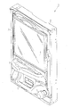
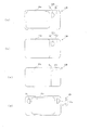
図1に示すように、パチンコ機1は、外枠2と、その前部に設けられた前面枠3とを備えている。前面枠3は外枠2の一側部にて開閉可能に装着されている。前面枠3の前面側には、ガラス扉枠4が開閉自在に設けられているとともに、ガラス扉枠4の下側において遊技球B(図2参照)を貯留するための上皿5が、上皿5の下方位置において同じく遊技球Bを貯留するための下皿6がそれぞれ設けられている。
As shown in FIG. 1, the
前面枠3の前面側の下皿6側方には操作手段としてのハンドル7が設けられており、ハンドル7は図示しない遊技球発射装置に連結されている。また、前面枠3の後側(ガラス扉枠4の奥、外枠2の内側)には、遊技盤8(図2参照)が着脱可能に装着されており、前記遊技球発射装置はこの遊技盤8の上部に向けて遊技球Bを発射する。なお、該遊技球発射装置は、発射制御基板140(図3参照)により制御される。
A
さらに、前面枠3内部(上皿5の側方)には、遊技の進行に伴い種々の効果音を鳴らしたり、遊技者に遊技状態を音声にて報知するためのスピーカ9が埋設されている。なお、スピーカ9は、音声制御基板130(図3参照)により制御される。 Further, a speaker 9 is embedded in the front frame 3 (side the upper plate 5) for sounding various sound effects as the game progresses and for notifying the player of the game state by voice. . The speaker 9 is controlled by a sound control board 130 (see FIG. 3).
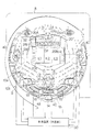
さて、図2に示すように、遊技盤8には、内レール10a及び外レール10bが設けられており、前記遊技球発射装置によって発射された遊技球Bは内レール10a及び外レール10bに沿って遊技盤8の上部に案内される。
Now, as shown in FIG. 2, the
遊技盤8の下部には、作動口11及び大入賞口12が設けられている。作動口11は遊技球B用の通路を備えるとともに、その通路入口には羽根13が開閉可能に支持されている。大入賞口12の奥にはシーソー14が設けられているとともに、その右側にはVゾーン15が、左側には入賞通路16がそれぞれ設けられている(左右逆でもよい)。つまり、大入賞口12に遊技球Bが入賞した場合、この遊技球Bはシーソー14によってVゾーン15又は入賞通路16のどちらかへ転がるように振り分けられ、Vゾーン15又は入賞通路16のどちらかを通って導出されるような構成となっている。
At the lower part of the
大入賞口12の前部には、大入賞口12を開閉するシャッタ17が設けられている。シャッタ17は大入賞口12の側部に設けられた大入賞口用ソレノイド18により作動させられる。詳しくは、大入賞口ソレノイド18が励磁状態となることにより、シャッタ17が略水平に傾き、大入賞口12が開かれる。また、大入賞口ソレノイド18が非励磁状態となることにより、シャッタ17が略垂直状態となり、大入賞口12は閉鎖されるようになっている。
A shutter 17 that opens and closes the big prize opening 12 is provided in front of the big prize opening 12. The shutter 17 is actuated by a large
さらに、大入賞口12の一側部には、シーソー用ソレノイド19が設けられている。通常、シーソー用ソレノイド19は非励磁状態となっており、この状態におけるシーソー14はVゾーン15の方へ傾いた状態となっている。つまり、遊技球BがVゾーン15を通過していくような傾きとなっている。また、シーソー用ソレノイド19が励磁状態となることにより、シーソー14は遊技球Bを入賞通路16に通過させるような傾きとなる。なお、本実施の形態では、シャッタ17の開状態において遊技球Bが1つでもVゾーン15を通過した場合には、シーソー用ソレノイド19が励磁状態となり、シャッタ17が閉じられた場合には、シーソー用ソレノイド19が非励磁状態となるように構成されている。
Furthermore, a
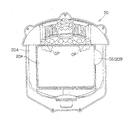
遊技盤8の中央部分には、可変表示装置としての特別図柄表示装置20が組込まれている。特別図柄表示装置20は、液晶ディスプレイ(LCD)装置によって構成され、対角線の長さが約7インチの略長方形状の表示画面20B(図6参照)を備えている。
A special
表示画面20Bは略矩形状の表示部としての主表示部20aを備えており、主表示部20aの周囲には、フレーム部材を構成する樹脂製のセンターフレーム20Aが配設されている。主表示部20aには複数の図柄列K1〜K3を表示することができるようになっている。本実施の形態において、これらの図柄列としては左図柄列K1、中図柄列K2及び右図柄列K3の3つの図柄列(識別情報列)が挙げられる(図5(a)参照)。但し、図柄列の数としては3つに限られるものではなく、それ以外の数の図柄列が表示されることとしてもよい。
The
さらに、特別図柄表示装置20の表示画面20B(主表示部20a)では、遊技球Bの作動口11への入賞に基づいて、各図柄列K1〜K3の図柄変動表示(本実施の形態においては、スクロール変動表示)が行われるような構成となっている。また、この変動表示中に新たな遊技球Bが作動口11に入賞した場合には、その分の変動表示は、その時点で行われている変動表示の終了後に行われる構成となっている。つまり、変動表示が待機(保留)されることとなる。この保留される変動表示の最大回数は、パチンコ機の機種毎に決められているが、本実施の形態では保留最大回数が4回に設定されている。しかし、保留最大回数は、これに限られるものではない。
Furthermore, on the
表示画面20Bの上方には、前述したような図柄の変動表示の保留回数を示す発光ダイオード(LED)からなる保留ランプ24a,24b,24c,24dが組み込まれている。保留ランプ24a〜24dの数は、前述した保留最大回数と同じ(この場合4個)となっている。保留ランプ24a〜24dは、変動表示の保留毎に点灯させられ、その保留に対応した変動表示の実行に伴い消灯させられる。
Above the
センターフレーム20Aの上部には、普通図柄表示装置31が併設されている。普通図柄表示装置31は、発光ダイオード(LED)よりなる4つの保留ランプ32と、普通図柄表示部たるLEDよりなる7セグ表示部33とを有している。また、特別図柄表示装置20の左右両側方には、一対の通過ゲート34が配設されており、同通過ゲート34を遊技球Bが通過すると普通図柄表示装置31が作動するような構成となっている。本実施の形態における普通図柄表示装置31は、「0」から「9」までの数字を可変表示して7セグ表示部33にセグメント表示させる。その数字が所定値(本実施の形態では「7」)で停止した場合に、作動口11の羽根13を所定秒数開放させるようになっている。普通図柄表示装置31は、遊技球Bの通過ゲート34の通過回数を4回まで記憶することができ、保留ランプ32でその保留数を表示する。従って、4つの保留ランプ32が点灯している状態で、遊技球Bが通過ゲート34を通過してもカウントされないようになっている。また、保留ランプ32が点灯している限り、遊技球Bが通過ゲート34を通過しなくとも保留数に応じた回数だけ普通図柄表示装置31は作動するようになっている。
A normal symbol display device 31 is provided on the
さらに、パチンコ機1の複数箇所には、遊技効果を高めるための他の図示しない各種演出用ランプや電飾部材が取付けられている。これらの演出用ランプや電飾部材等(以下単に「ランプ」と称する)の点灯状態(消灯、点灯、点滅等)は、遊技の進行に応じて適宜変えられるようになっている。なお、これらランプは、ランプ制御基板120(図3参照)により制御される。
Furthermore, other various production lamps and electrical decoration members (not shown) for enhancing the gaming effect are attached to a plurality of locations of the
また、遊技盤8には、遊技者の操作に応じて変化するパチンコ機1の遊技状態を検出するためのスルースイッチ40、作動口用スイッチ41、Vゾーン用スイッチ42及びカウントスイッチ43等の各種センサがそれぞれ取付けられている。スルースイッチ40は、遊技球Bの通過ゲート34の通過を検出するものであり、作動口用スイッチ41は、遊技球Bの作動口11への入賞を検出するものであり、Vゾーン用スイッチ42は、遊技球Bの大入賞口12のうちのVゾーン15への入賞を検出するものであり、カウントスイッチ43は、遊技球Bの大入賞口12への入賞を検出するものである。
Further, the
さて、本実施の形態では、各スイッチ40〜43の検出結果に基づき、各ソレノイド18,19、特別図柄表示装置20、各保留ランプ24a〜24d、スピーカ9、普通図柄表示装置31(保留ランプ32及び7セグ表示部33)、羽根13等をそれぞれ駆動制御するため制御装置(主基板)50が設けられている。
In the present embodiment, the
主基板50は、主たる制御を司るためのものであって、読み出し専用メモリ(ROM)、中央処理装置(CPU)、ランダムアクセスメモリ(RAM)等を備えている。ROMは所定の制御プログラムや初期データを予め記憶しており、CPUはROMの制御プログラム等に従って各種演算処理を実行する。RAMはCPUによる演算結果を図柄乱数バッファ、図柄乱数エリア、停止図柄エリア等に一時的に記憶する。なお、主基板50はパチンコ機1の裏側の図示しない基板ボックス内に封印された状態で装着されている。
The
また、RAMは、後述する特別遊技状態としての大当たり状態の発生を決定するための乱数カウンタをも備えている。この乱数カウンタは、乱数更新処理により、所定(例えば「0」〜「299」)の範囲で、例えば2ms毎に、1カウントずつ更新される。本実施の形態では、遊技球Bが作動口11に入賞し、それが作動口用スイッチ41にて検出されたときに(保留最大回数時は除く)、前記乱数カウンタの値が所定値、例えば「7」であった場合に、大当たり状態が発生させられるようになっている。 The RAM also includes a random number counter for determining occurrence of a jackpot state as a special gaming state described later. The random number counter is updated by one count every 2 ms, for example, within a predetermined range (for example, “0” to “299”) by random number update processing. In the present embodiment, when the game ball B wins the operating port 11 and is detected by the operating port switch 41 (except for the maximum number of times of holding), the value of the random number counter is a predetermined value, for example, In the case of “7”, a big hit state is generated.
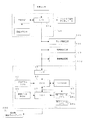
上記CPU、ROM及びRAMは、バスラインを介して互いに接続されている。図3のブロック図に示すように、バスラインは、主基板50のインターフェイス50aにも接続されており、インターフェイス50aは、コネクタ及びケーブル等を介して表示制御基板110のインターフェイス61や他の装置と接続されている。また、インターフェイス50aは、コネクタ及びケーブル等を介して作動口スイッチ41等の各種センサに接続されている。すなわち、主基板50は、作動口スイッチ41等からインターフェイス50aを介して入賞信号等を入力するとともに、インターフェイス50aを介して表示制御基板110や他の入出力装置(他の制御基板を含む)へ制御データ等の各種動作コマンドを出力し、各ソレノイド等の各種アクチュエータ及び各制御基板を制御する。
The CPU, ROM and RAM are connected to each other via a bus line. As shown in the block diagram of FIG. 3, the bus line is also connected to the
さて、本実施の形態では、特別図柄表示装置20の表示画面20Bにおける各種表示制御は、主たる制御を行う主基板50ではなく、主として特別図柄表示装置20の表示制御基板110において行われるように構成されている。なお、表示制御基板110は、特別図柄表示装置20に組み込まれた状態となっている。
Now, in the present embodiment, various display controls on the
さらに、本実施の形態においては、各種(演出用の)ランプの点灯、点滅制御については、主としてランプ制御基板120において行われ、スピーカ9から発せられる音声の制御については、主として音声制御基板130において行われる。また、前記遊技球発射装置における遊技球Bの発射制御についても、主基板50ではなく、発射制御基板140において行われるような構成となっている。
Further, in the present embodiment, lighting and blinking control of various (production) lamps is mainly performed in the lamp control board 120, and control of sound emitted from the speaker 9 is mainly performed in the sound control board 130. Done. Further, the launch control of the game ball B in the game ball launching apparatus is also performed on the
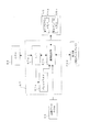
ここで、主として本実施の形態における表示制御を行う表示制御基板110の電気的構成について、図3のブロック図に従って説明する。同図に示すように、表示制御基板110は、主基板50から送られてくるコマンドを順次受信するインターフェイス61と、プログラムROM62に記憶された制御プログラム及び各種の情報に基づいて、各種遊技状態(通常変動やリーチ演出や大当たり報知等)において表示される表示画像の画面構成情報を生成するCPU63と、CPU63での処理結果等を一時的に記憶するワークRAM64と、CPU63で生成された画面構成情報を記憶するビデオRAM65と、ビデオRAM65に記憶された画面構成情報に基づいて画像データROM66から画像データを取り出し、そのデータを画面構成情報に書き込むことにより各種遊技状態における表示画像を生成するVDP67とを備えている。そして、生成された表示画像は表示部(液晶ディスプレイ)20Bへ出力される。
Here, the electrical configuration of the
インターフェイス61は、主基板50から送信されてくるコマンド(指令)を受信する。また、それらのコマンドは、CPU63によってワークRAM64に設けられた図示しないコマンドバッファ領域に記憶される。
The interface 61 receives a command (command) transmitted from the
CPU63は、プログラムROM62に記憶された制御プログラムに従って動作する。具体的には、前記コマンドを監視して、該コマンドに応じたタスクを生成し、ワークRAM64に記憶する。そのタスクを実行することで、ワークRAM64内に各種遊技状態(通常変動やリーチ演出や大当たり報知等)において表示される表示画像の画面構成情報を生成し、この画面構成情報をビデオRAM65に書き込む。なお、画面構成情報は、表示画面(液晶ディスプレイ)20Bの垂直操作信号(VSYNC)ごとに生成される。
The CPU 63 operates according to a control program stored in the program ROM 62. Specifically, the command is monitored, a task corresponding to the command is generated, and stored in the work RAM 64. By executing the task, screen configuration information of a display image displayed in various game states (normal fluctuation, reach production, jackpot notification, etc.) is generated in the work RAM 64, and this screen configuration information is written in the
ワークRAM64には、主基板50からのコマンドを記憶するための前記コマンドバッファ領域をはじめ、生成されたタスクが記憶されるタスクバッファ領域や、画像構成情報(通常変動時やリーチ状態時の図柄画像の指示や、その配置位置や表示優先順位等)を一括してビデオRAM65に書き込むために各種情報が記憶されるスプライトチェーン領域(いずれも図示略)が設定される。
The work RAM 64 includes a command buffer area for storing commands from the
ビデオRAM65は、前記画像構成情報を記憶するとともに、VDP67で生成される表示画像のデータを記憶するメモリである。ビデオRAM65には、表示画面20Bに表示される主として一画面分の表示画像のデータを記憶する記憶領域である第1フレームメモリ65aと第2フレームメモリ65bが設けられており、CPU63が生成した画像構成情報並びにVDP67で生成される表示画像のデータを交互に記憶することができるような構成となっている。
The
画像データROM66は、表示画面20Bに表示される図柄や背景画像等の各種画像データを記憶するメモリである。前記画像データには、図柄や背景画像等の例えば形状、サイズ、模様、配色、色調等を定めた図柄や背景画像等を生成するために必要な各種情報が含まれている。
The image data ROM 66 is a memory for storing various image data such as symbols and background images displayed on the
VDP67は、表示画像の画像生成処理を行う画像データプロセッサである。つまり、VDP67は、ビデオRAM65に記憶された画像構成情報に基づいて、画像データROM66に記憶されている画像データを読み出し、前記画像データに含まれる情報を前記画像構成情報に書き込むことにより、表示画面20Bに表示可能な表示画像を生成する。そして、生成した表示画像を表示画面20Bに出力する。
The VDP 67 is an image data processor that performs image generation processing of a display image. That is, the VDP 67 reads out the image data stored in the image data ROM 66 based on the image configuration information stored in the
さらに詳しくは、図4に示すように、VDP67は、CPU63から送られてくる各種コマンドやデータを受信するインターフェイス67aと、インターフェイス67aから送られる各種コマンドやデータに基づいてビデオRAM65に記憶された画像構成情報を読み出し、該画像構成情報に基づいて表示画像を生成する画像生成部67bと、表示画像のカラー情報を格納するパレットRAM67cとから構成されている。
More specifically, as shown in FIG. 4, the VDP 67 has an interface 67a for receiving various commands and data sent from the CPU 63, and an image stored in the
インターフェイス67aから各種コマンドやデータを受け取った画像生成部67bは、ビデオRAM65の第1フレームメモリ65a又は第2フレームメモリ65bに記憶された画像構成情報を読み出す。その画像構成情報に基づいて画像データROM66から画像データを読み出し、前記画像データに含まれる各種情報を該画像構成情報に書き込む。同時に、前記画像データに対応するカラー情報をパレットRAM67cから取得し、前記画像構成情報に書き込む。これにより、カラー情報に基づく配色を施した表示画像が生成される。
The image generation unit 67b that receives various commands and data from the interface 67a reads the image configuration information stored in the first frame memory 65a or the
同時に、画像生成部67bは、前記書き込みが行われていない第1フレームメモリ65a又は第2フレームメモリ65bに記憶されている表示画像のデータを読み出し、表示画面(液晶ディスプレイ)20Bに出力する。この際、表示画像のデータはRGB信号で出力され、このRGB信号に基づいて、色調(色、彩度、輝度、コントラストなど)等が制御されて表示画面(液晶ディスプレイ)20Bに表示される。また、表示画像のデータが出力され、何もデータが記憶されていない第1フレームメモリ65a又は第2フレームメモリ65bには、新たな画像構成情報が書き込まれる。なお、画像生成部67bにおいて生成される表示画像は、図柄及び背景画像用等の複数のレイヤによって構成されており、これらを重ね合わせ、主として1画面分の表示画像として生成している。
At the same time, the image generation unit 67b reads the display image data stored in the first frame memory 65a or the
パレットRAM67cは、複数種類のカラー情報を設定した複数種類のカラーパレットを保持しており、画像データに含まれるカラー情報に応じたカラーパレットを画像生成部67bに与えるものである。ここで、カラーパレットを与えるとは、例えば、パレットRAM67cに格納されたカラーパレットの格納アドレスを画像生成部67bに与えることを意味している。なお、カラー情報は、原色例えば赤色(R)、緑色(G)、青色(B)の基本色情報を組み合わせた配合割合等によって、定められているものである。
The
ここで、特別図柄表示装置20の表示画面20Bにおいて、遊技状態中等に表示される表示画像の構成について具体的に説明するとともに、その表示態様を基に大当たり状態、リーチ状態、外れ状態等についても説明する。
Here, on the
特別図柄表示装置20の表示画面20Bの主表示部20aには、図5(a)に示すように、森の中の景色を表す背景画像が表示され、その前側に位置するように、各図柄列K1〜K3が表示されるようになっている。各図柄列K1〜K3は、図5等に示すように、それぞれ複数種類かつ複数個の識別情報としての図柄70A〜70I及び外れ図柄70Jによって構成されている。外れ図柄70Jを除く各図柄70A〜70Iは、それぞれ各種果実や葉の絵と「1」〜「9」の数字との組合せによって構成されている(勿論、各種絵柄、各種文字のみ、或いは、数字や文字に各種絵柄が組合わさったものを図柄として使用してもよい)。これらの図柄70A〜70Iは、左図柄列21については降順に、中、右図柄列22,23については基本的には昇順にそれぞれ配列されている。これらの図柄70A〜70Iは、特別遊技図柄としての大当たり図柄、外れリーチ図柄及び外れ図柄のいずれかになりうる(これらについては後述する)。
As shown in FIG. 5 (a), a background image representing the scenery in the forest is displayed on the
また、外れ図柄70Jは「どんぐり」のマークによって構成されており、基本的には前記図柄70A〜70I間に配置される。さらに、当該外れ図柄70Kは、その名のとおり、大当たり図柄になることはなく、外れ図柄にのみなりうる。但し、「1」と「9」の図柄70A,70Iの間には、外れ図柄70Jの代わりに、「4」の図柄70Dが配置されている。かかる配置構成により、「1」と「9」の所謂ダブルリーチが発生可能となっているとともに、後述する大当たり図柄が偶数と奇数との間で均等に生じうるようになっている。
Further, the
各々の図柄列K1〜K3においては、表示される図柄70A〜70Jが、上から下方向へと移動するかのごとく表示される。なお、各図柄列K1〜K3において、図柄70A〜70Jの配列順序をランダムに変更し変動表示させたり、図柄70A〜70Jの数を適宜増減させたり、1つの図柄列に同じ図柄を複数個表示したり、図柄70A〜70Jの変動表示態様、例えばスクロール変動表示や差換変動表示等を適宜変更したりしてもよい。 In each of the symbol rows K1 to K3, the displayed symbols 70A to 70J are displayed as if they move from top to bottom. In each of the symbol columns K1 to K3, the arrangement order of the symbols 70A to 70J is randomly changed to be displayed in a variable manner, the number of symbols 70A to 70J is appropriately increased or decreased, and a plurality of the same symbols are displayed in one symbol column. Or the change display mode of the symbols 70 </ b> A to 70 </ b> J, for example, scroll change display, replacement change display, or the like may be changed as appropriate.
さて、上述したように変動表示される各図柄列K1〜K3の各図柄70A〜70Jは、所定時間経過後、主表示部20aの大当たりラインL1〜L5上に停止表示される(図5(c)参照)。このとき、大当たり図柄、外れリーチ図柄、外れ図柄の中から1つが選択された上で、前記大当たりラインL1〜L5上に停止表示される。なお、停止図柄とは、各図柄列K1〜K3が図柄変動を停止したときに確定表示される図柄である。また、本実施の形態では、図柄変動は、左図柄列K1、右図柄列K3、中図柄列K2の順に停止させられる。
As described above, the symbols 70A to 70J of the symbol rows K1 to K3 that are variably displayed are stopped and displayed on the jackpot lines L1 to L5 of the
次に、遊技者に有利な特別遊技状態としての大当たり状態について説明する。図5(c)は、主表示部20aにおける大当たり状態発生時の画面を示す図である。同図に示すように、大当たり図柄は、通常遊技状態からリーチ遊技状態(リーチ状態)を経た後、遊技者に有利な特別遊技状態としての大当たり状態を発生させるための図柄である。詳しくは、全ての図柄列K1〜K3の変動が停止させられたとき、表示されている図柄70A〜70Iの組合せが、予め定められた大当たりの組合せ、すなわち、同一種類の図柄70A〜70Iが大当たりラインL1〜L5に沿って並んでいるときの同図柄70A〜70Iの組合せとなる場合がある。この組合せを構成する図柄が「大当たり図柄」である。
Next, the jackpot state as a special gaming state advantageous to the player will be described. FIG. 5C is a diagram showing a screen when a big hit state occurs in the
本実施の形態では、上中下の横ラインL1,L2,L3及び斜めの2本のラインL4,L5によって大当たりラインL1〜L5が構成されている(5ラインと称される)。大当たりの組合せが成立すると、特別電動役物が作動し(大入賞口4が開かれ)、遊技者にとって有利な大当たり状態の到来、すなわち、より多くの景品球を獲得することが可能となる。(例えば図5(c)では下段のラインL3において「7」「7」「7」の図柄70Gが揃って停止表示されている)。
In the present embodiment, the jackpot lines L1 to L5 are configured by the upper, middle, and lower horizontal lines L1, L2, and L3 and the two diagonal lines L4 and L5 (referred to as five lines). When the jackpot combination is established, the special electric accessory is activated (the jackpot 4 is opened), and it is possible to obtain a jackpot state that is advantageous to the player, that is, to obtain more prize balls. (For example, in FIG. 5C,
本実施の形態では、一旦大当たり状態が発生すると、大入賞口12の開放後、(1)遊技球Bが大入賞口12への10個入賞すること、(2)約29.5秒が経過すること、のいずれか一方の条件が満たされた時点で大入賞口12が閉鎖される。この大入賞口12の開閉のサイクルが遊技球BのVゾーン15への入賞を最大で所定回数(例えば16回:16ラウンド)繰り返されることとなる。
In this embodiment, once a big hit state occurs, after the grand prize opening 12 is opened, (1) 10 game balls B win the big prize opening 12, and (2) about 29.5 seconds have elapsed. When either one of the conditions is satisfied, the special winning opening 12 is closed. This open / close cycle of the big prize opening 12 is repeated a maximum of a predetermined number of times (for example, 16 times: 16 rounds) in which the game ball B wins the
また、リーチ状態とは、大当たり直前の状態をいう(もちろん大当たり状態に至らない場合もある)。図5(b)に示すように、リーチ状態には、右図柄列K3の図柄変動が、前記大当たりラインL1〜L5上において左図柄列K1の停止図柄と同一種類の図柄で停止する状態が含まれる。 The reach state means a state immediately before the jackpot (of course, the jackpot state may not be reached). As shown in FIG. 5B, the reach state includes a state in which the symbol variation of the right symbol row K3 stops on the jackpot lines L1 to L5 with the same kind of symbols as the stop symbol of the left symbol row K1. It is.
上記のリーチ状態には、中図柄列K2の図柄変動が、最終的に左・右両図柄列K1,K3の停止図柄と同一種類の図柄(大当たり図柄)で停止して大当たり状態になるもの以外にも、異なる種類の図柄(これを「外れリーチ図柄」という)で停止して、大当たり状態とならないもの(以下、「外れリーチ状態」という)が含まれる。さらには、中図柄列K2の図柄変動が一旦停止した後(停止しかけた後)、全図柄列(或いは一部の図柄列)が変動し、その後全図柄列K1〜23の図柄70A〜70Jが停止するような場合(再変動リーチ、全回転リーチとも称される)も含まれる。 In the above reach state, the symbol variation of the middle symbol row K2 will eventually stop at the same kind of symbol (big hit symbol) as the stop symbols of both the left and right symbol rows K1 and K3 and will be in a big hit state Also included are those that stop at different types of symbols (this is referred to as “outgoing reach design”) and do not become a big hit state (hereinafter referred to as “outgoing reach state”). Furthermore, after the symbol variation of the middle symbol row K2 is temporarily stopped (after stopping), all symbol rows (or some symbol rows) are fluctuated, and thereafter the symbols 70A to 70J of all symbol rows K1 to 23 are changed. The case of stopping (also referred to as re-variation reach or full rotation reach) is also included.
上記リーチ状態において、リーチパターンとしては、中図柄列K2の図柄70A〜70Jが通常変動時と同様に単にスクロールする「ノーマルリーチ」の外に、種々のリーチパターンが設定されている。これらリーチパターンのうち、「ノーマルリーチ」以外のリーチパターンは、いわゆる「スーパーリーチ」と称されるものである。「スーパーリーチ」の動作が開始された場合には、「ノーマルリーチ」の場合に比べて、大当たり状態が発生する期待値(大当たり期待値)が高くなるようになっている。また、「スーパーリーチ」においても、各リーチパターンによって大当たり期待値が異なったものとなっていることとしてもよい。また、「スーパーリーチ」よりも大当たり期待値の高い「スペシャルリーチ」や「プレミアムリーチ」と称されるリーチパターンを用意することとしてもよい。 In the reach state, as the reach pattern, various reach patterns are set in addition to “normal reach” in which the symbols 70A to 70J in the middle symbol row K2 are simply scrolled in the same manner as in the normal variation. Among these reach patterns, reach patterns other than “normal reach” are so-called “super reach”. When the operation of “super reach” is started, the expected value (expected value for jackpot) at which a big hit state occurs is higher than in the case of “normal reach”. Also, in “super reach”, the jackpot expectation value may differ depending on each reach pattern. In addition, a reach pattern called “special reach” or “premium reach” having a higher jackpot expectation value than “super reach” may be prepared.
本実施の形態では、「スーパーリーチ」として、「リス」が表示されることにより演出が行われる「リスリーチ」、「ももんが」が表示されることにより演出が行われる「ももんがリーチ」等が設定されている。 In this embodiment, “Super Reach” is set to “Risle Reach” that produces an effect when “Squirrel” is displayed, “Monomon Reach” that produces an effect when “Monmonga” is displayed, etc. ing.
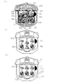
さて、本実施の形態では、図6,7に示すように、表示画面20Bは、上述した図柄70A〜70Jが変動表示される主表示部20aのみならず、副表示部20bをも備えている。より詳しくは、表示画面20Bは、略長方形状のワイド画面となっており、対角線の長さがおよそ7インチに設定されている。前記主表示部20aは、略長方形状に形成されており、対角線の長さがおよそ6インチに設定されており、表示画面20Bのほぼ中央位置に設けられている。そして、表示画面20Bから主表示部20aを除いた部分が副表示部20bとなっている。さらに、副表示部20bは、表示対象としてのリスRC(図8(a)参照)を表示可能な逸脱表示領域CSと、表示対象が表示されることのない非表示領域NSとからなっている。本実施の形態における逸脱表示領域CSは、主表示部20aに隣接して設定されているが、主表示部20aから離間した部位に設定されていても差し支えない。前記主表示部20aと副表示部20bとは共に前記表示制御基板110によって表示制御されるのであるが、その存在は、互いに独立したものであって、その境界線は、図柄70A〜70Jの表示領域を画定するものである。しかも主表示部20aは、従来と同様略長方形状をなしており、副表示部20bの存在によって主表示部20aでの表示が阻害されないようになっている。
In the present embodiment, as shown in FIGS. 6 and 7, the
また、副表示部20bの非表示領域NSは、常に真っ黒な画像が表示されるようになっているとともに、逸脱表示領域CSも、通常は前記非表示領域NSと同様真っ黒な画像が表示され、「リスリーチ」の演出が行われる場合に限って逸脱表示領域CSにリスRCが表示されるようになっている。
In addition, the non-display area NS of the
さらに、副表示部20bのうち、前記逸脱表示領域CSを除く部分は、センターフレーム20Aで覆われている。本実施の形態におけるセンターフレーム20Aは木目模様を呈しており、これにより主表示部20aに森の背景画像が表示された場合に渾然一体感が付与されるようになっている。このような構成により、遊技者にとっては、あたかもセンターフレーム20Aの内側に主表示部20aが配されており、それとは別に副表示部20bの逸脱表示領域CSを確保するための表示画面が設置されているかの如く印象を受けるようになっている。なお、センターフレーム20Aのうち、前記逸脱表示領域CSに対応する部位には、透明な窓部が設けられており、逸脱表示領域CSに表示されるリスRCは、前記窓部を介して視認可能となっている。
Further, a portion of the
また、図7に示すように、センターフレーム20Aの上部には、枝葉をモチーフとした一対の開閉部材OPが設けられている。当該開閉部材OPは、図示しない開閉部材用ソレノイドによって開閉可能に軸支されており、通常は、略一直線状になるよう閉鎖状態に維持されている(図5(b),(c)等参照)。また、前記ソレノイドが励磁状態とさせられることにより、同図に示すように開閉部材OPが下方に開かれるようになっている。開閉部材OPは、後述する「ももんがリーチ」の演出が行われるに際してのみ開閉制御されるようになっている。
Further, as shown in FIG. 7, a pair of opening / closing members OP having branches and leaves as motifs are provided on the upper portion of the
次に、上記のように構成されたパチンコ機1における各制御部の作用及び効果について説明する。
Next, the operation and effect of each control unit in the
まず、作動口用スイッチ41からの検出信号に基づき、遊技球Bが作動口11へ入賞した旨が主基板50によって認識された場合の制御処理について説明する。
First, the control process when the
主基板50が遊技球Bが作動口11へ入賞した旨を検出した場合、そのことに基づいて、主基板50は、対応する保留ランプ24a〜24d(例えば、それまで2つの保留ランプ24a及び24bの2つの保留ランプが点灯されていた場合には3つ目の保留ランプ24c)を点灯させ、保留カウンタの値を「1」ずつインクリメントする。但し、保留ランプ24a〜24dが全て点灯している場合は除かれる。
When the
また、主基板50は、内部乱数カウンタ、大当たり図柄カウンタ、外れリーチ図柄カウンタ、外れ図柄カウンタ等の各カウンタの値を各乱数エリアに格納する。そして、所定のタイミングにおいて対応する保留ランプ24a〜24dを消灯させるとともに、保留カウンタの値をデクリメントし、各エリア等に格納されたデータに基づき図柄変動を実行する。
The
このとき、主基板50は、当該変動に際し、指令としてのコマンドを特別図柄表示装置20の表示制御基板110をはじめ、ランプ制御基板120、音声制御基板130等へと出力(送信)する。さて、当該コマンドには、(1)変動開始から所定時間後に図柄70A〜70Jを確定停止表示させる旨の時間情報及び各リーチパターンに代表される変動パターンからなるパターン情報、並びに、(2)いかなる図柄70A〜70Jで確定表示させるかという図柄情報が含まれる。ここで、図柄情報としては、大当たり図柄、外れリーチ図柄、外れ図柄が含まれ、これらは、上述した内部乱数カウンタ、大当たり図柄カウンタ、外れリーチ図柄カウンタ、外れ図柄カウンタ等に基づいて決定されるものである。
At this time, the
本実施の形態における上記コマンドは、2バイト構成からなっており、順次連続的に表示制御基板110等へと送信される。2バイト構成からなるコマンドのうち、先頭の1バイト目は、これからいかなる情報が送信されてくるかというキーワード情報によって構成されている。また、後半の1バイトは、具体的な指示内容に該当するパターンコード等の内容情報によって構成されている。
The command in the present embodiment has a 2-byte configuration, and is sequentially transmitted to the
例えば、本実施の形態において、まず最初に送信されるコマンドはパターン情報である。この場合、1バイト目は、これからパターン情報(時間情報及び変動パターンを示唆する)が送信される旨のキーワード情報により構成され、2バイト目は、「00」、「01」等のパターンコード情報により構成されている。ここで、「00」、「01」等のパターンコード情報は、図柄の変動時間を例えば「10秒」とする、或いは、「30秒」とするといった内容を示唆する時間情報と、どのような変動パターン(又は変動パターン群のうちいずれか)を実行するといった変動パターンを示唆する情報とからなる。 For example, in the present embodiment, the first command transmitted is pattern information. In this case, the first byte is composed of keyword information indicating that pattern information (indicating time information and a variation pattern) is to be transmitted, and the second byte is pattern code information such as “00” and “01”. It is comprised by. Here, the pattern code information such as “00”, “01”, and the like is time information that suggests the content such as “10 seconds” or “30 seconds” as the symbol variation time. It consists of information suggesting a fluctuation pattern such as executing a fluctuation pattern (or any one of fluctuation pattern groups).
続いて送信されるのは図柄情報である。すなわち、本実施の形態のように左→右→中の順に3つの図柄列K1〜K3の図柄が確定させられる場合においては、まず、パターン情報に続いて2番目に送信されるコマンドたる図柄情報として、1バイト目は、これから左図柄列K1の図柄情報が送信される旨のキーワード情報により構成され、2バイト目は、確定表示される図柄を示唆するパターンコード情報により構成されている。また、3番目に送信されるコマンドたる図柄情報として、1バイト目は、これから右図柄列K3の図柄情報が送信される旨のキーワード情報により構成され、2バイト目は、確定表示される図柄を示唆するパターンコード情報により構成されている。併せて、4番目に送信されるコマンドたる図柄情報として、1バイト目は、これから中図柄列K2の図柄情報が送信される旨のキーワード情報により構成され、2バイト目は、確定表示される図柄を示唆するパターンコード情報により構成されている。このように、確定図柄に関する3つの表示情報がたて続けに送信される。すなわち、1回の図柄変動に際して、2バイト構成からなるデータが1バイトずつ送信されることにより、合計8(1×2+3×2)回のデータ送信が行われることとなる。 Subsequently, the symbol information is transmitted. That is, in the case where the symbols of the three symbol sequences K1 to K3 are determined in the order of left → right → middle as in the present embodiment, first, the symbol information that is the second command transmitted following the pattern information. The first byte is composed of keyword information indicating that the symbol information of the left symbol string K1 will be transmitted from now on, and the second byte is composed of pattern code information suggesting a symbol to be confirmed and displayed. In addition, as the symbol information that is the third command to be transmitted, the first byte is composed of keyword information indicating that the symbol information of the right symbol column K3 will be transmitted from now on, and the second byte is a symbol that is confirmed and displayed. It consists of suggested pattern code information. In addition, as symbol information that is the fourth command to be transmitted, the first byte is composed of keyword information indicating that symbol information of the middle symbol string K2 will be transmitted from now on, and the second byte is a symbol that is confirmed and displayed. It consists of pattern code information that suggests. In this way, three pieces of display information related to the confirmed symbol are transmitted continuously. In other words, when the symbol changes once, data having a 2-byte structure is transmitted byte by byte, so that a total of 8 (1 × 2 + 3 × 2) data transmissions are performed.
なお、上記実施の形態では、左、右、中の各図柄列K1〜K3に対応した図柄情報が送信されることとなっているが、例えば8つの図柄を確定表示させる必要がある場合には、1×2+8×2=18回のデータ送信が行われるといった具合に、図柄数を適宜変更した場合であっても適用することができる。 In the above embodiment, symbol information corresponding to each of the left, right, and middle symbol columns K1 to K3 is transmitted. For example, when eight symbols need to be confirmed and displayed, Even if the number of symbols is changed as appropriate, such as 1 × 2 + 8 × 2 = 18 times of data transmission, it can be applied.
また、本実施の形態では、コマンド(一群のコマンド)が、表示制御基板110に対してのみならず、ランプ制御基板120、音声制御基板130にも同期して出力されるようになっている(厳密な意味で全く同時でなくてよい)。勿論、このときに出力されるコマンドは、表示制御基板110に出力されるコマンドに対応したものであることが望ましい(場合によっては対応していなくてもよい)。これに対し、図柄変動に関する一群のコマンド(1回の図柄変動に際して送られてくるデータ群)を受信した表示制御基板110は、特別図柄表示装置20の表示画面20Bで表示する表示画像(主表示部20aにおける背景画像及び図柄画像、並びに、副表示部20bの逸脱表示領域CSにおけるキャラクタ画像等)を順次生成する。
In the present embodiment, commands (a group of commands) are output not only to the
さらに、表示制御基板110は、当該コマンドに基づき図柄変動を開始するとともに、変動停止に至るまでの間、前記変動パターンに基づく種々の演出を行う。当該演出としては、例えばリーチ演出が主として挙げられる。
Further, the
すなわち、上記コマンドのうち、パターン情報に基づき、表示制御基板110のCPU63は、テーブルを参酌して、上述した各変動パターンの中から所定のパターンを選択決定するとともに、当該決定したパターンに基づく演出を、変動開始から確定表示までの間、別途設定された時間データの秒数分だけ実行する。さらにその後、主基板50側のCPUは、自身が有するタイマに基づき、前記所定時間に応じたタイミングで、表示制御基板110に対し、確定コマンドを出力する。
That is, based on the pattern information among the above commands, the CPU 63 of the
一方、表示制御基板110のCPU63は前記一旦停止からさらに所定時間後において(時間情報に基づく変動を完了した時点で)、前記図柄情報に応じた図柄を確定停止表示させる。このとき、結果的に前記出力された確定コマンドに同期して、図柄70A〜70Jが確定停止表示させられることとなる。同様に、ランプ制御基板120、音声制御基板130の各CPUも、前記タイミングにおいて、ランプ演出、音声演出を確定停止させる。
On the other hand, the CPU 63 of the
なお、本実施の形態では、変動パターンに関し、リーチ演出以外の演出に関しても、上記と同様に変動パターン情報に盛り込まれた上で制御が行われる。リーチ演出以外の演出としては、すべり変動、再変動、リーチ予告、スーパーリーチ予告、大当たり予告等の演出が挙げられる。ここで、「予告」とあるのは、演出によって、所定の遊技状態が発生しやすくなることを示唆可能であればよい、或いは、演出によって所定の遊技状態の発生率に影響が生じるという趣旨であって、所定の遊技状態が発生しない場合があっても差し支えない(示唆)。このように、本実施の形態では、主基板50によって主たる制御が司られ、該主基板50からのコマンドに基づいて、表示制御基板110等によって表示制御等が司られることとなっている。これにより、主基板50の負担軽減が図られている。
In the present embodiment, with respect to the variation pattern, effects other than the reach effect are also controlled after being included in the variation pattern information in the same manner as described above. The effects other than the reach effect include effects such as slip change, re-change, reach notice, super reach notice, and jackpot notice. Here, the “notice” only needs to be able to suggest that the predetermined gaming state is likely to occur due to the effect, or the effect that the occurrence rate of the predetermined gaming state is affected by the effect. Therefore, there is no problem even if the predetermined gaming state does not occur (suggestion). Thus, in the present embodiment, main control is governed by the
次に、本実施の形態の作用及び効果について説明する。主基板50から表示制御基板110に対し、図柄変動を行うべくコマンドが出力されると、表示制御基板110側では、図柄変動を開始させる。該変動に際しては、上述したように、表示される図柄70A〜70Jが上から下方向へと移動しているかの如く変動表示される。そして、各図柄列K1〜K3に対応する図柄70A〜70Jが、左図柄列K1、右図柄列K3、中図柄列K2の順で確定停止表示させられる。ここで、本実施の形態では、いわゆる5ラインを採用しているため、各図柄列K1〜K3毎に3つずつの図柄70A〜70Jが表示された上で確定停止されることとなる。つまり、主表示部20a上には、合計9つの図柄70A〜70Jが確定停止表示させられる。
Next, the operation and effect of the present embodiment will be described. When a command is output from the
さて、全図柄列K1〜K3の図柄70A〜70Jの確定停止表示に至るまでの間、リーチ状態が発生することがあり、前記コマンドによっては上述した「スーパーリーチ」の演出が行われる場合がある。以下には、代表的な2種類の「スーパーリーチ」たる「リスリーチ」及び「ももんがリーチ」の演出表示態様について説明する。 The reach state may occur until the symbols 70A to 70J of all symbols K1 to K3 are confirmed and stopped, and the above-described "super reach" effect may be performed depending on the command. . In the following, a description will be given of the effect display modes of two types of “Super Reach”, “Risu Reach” and “Monmon Reach”.
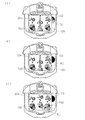
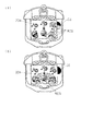
まず、図8,9に基づいて「リスリーチ」の演出表示態様について説明する。すなわち、前記図柄変動を行うべく表示制御基板110に対し出力されるコマンドに、「リスリーチ」演出を行う旨の情報が含まれていた場合において、表示制御基板110側で行われる処理内容について詳述する。この場合においては、表示制御基板110のCPU63により、各図柄列K1〜K3の図柄70A〜70Jの変動が開始させられる。
First, based on FIGS. 8 and 9, the effect display mode of “Lith Reach” will be described. That is, in the case where the command output to the
そして、変動開始から所定時間経過後において、まずは左図柄列K1の図柄変動速度がそれまでの変動速度よりも遅くされた後、図8(a)に示すように、所定の図柄70A〜70Jにて停止させられる(図では、下段に「7」の図柄70Gが停止表示されている)。続いて、左図柄列K1と同様、右図柄列K2の図柄変動速度が遅くさせられ、その後停止させられる(図では左図柄列K1と同様、下段に「7」の図柄70Gが停止表示されている)。この時点(中図柄列K2は未だ変動中)で、リーチ状態が発生するのであるが、かかるタイミング以降において、CPU63により、次のような制御が行われる。 Then, after a predetermined time has elapsed since the start of the fluctuation, first, after the symbol fluctuation speed of the left symbol row K1 has been made slower than the fluctuation speed until then, as shown in FIG. (In the figure, the symbol “7G” of “7” is stopped and displayed in the lower row). Subsequently, as with the left symbol row K1, the symbol fluctuation rate of the right symbol row K2 is slowed down and then stopped (in the figure, as in the left symbol row K1, the symbol “7G” in the lower row is stopped and displayed. ) At this time (the middle symbol row K2 is still fluctuating), the reach state occurs. After this timing, the CPU 63 performs the following control.
すなわち、同図に示すように、副表示部20bの逸脱表示領域CSにリスRCが表示されるとともに、該リスRCがあたかも家の窓から顔を覗かせているような表示制御が行われる。これを視認した遊技者は、主表示部20aにおける図柄70A〜70J変動のみならず、副表示部20bの逸脱表示領域CSに表示されるリスRCに驚きを覚えるとともに、主表示部20a以外での表示に対し今までにないような趣を覚える。そして、遊技者にとって好ましい事態(ここでは、さらなる発展型のリーチ演出、ひいては大当たり状態の発生)が起こるのではないかという期待感が高められる。
That is, as shown in the figure, the squirrel RC is displayed in the deviation display area CS of the
次に、さらなる発展型のリーチ演出が行われる場合と、そのまま外れ状態になる場合とがあり、そのまま外れになる場合には、例えばリスRCが逸脱表示領域CSから消えるような表示制御が行われる。これを視認した遊技者は、副表示部20bにリスRCが表示されなくなった(家の中に隠れてしまった)ことを残念がる一方で、主表示部20aとは別の箇所に、表示対象(リスRC)が表示されていたことに関する余韻を味わう。
Next, there is a case where a further advanced type of reach effect is performed and a case where it is left as it is, and when it is left as it is, display control is performed such that, for example, the squirrel RC disappears from the departure display area CS. . The player who has visually recognized this regrets that the squirrel RC is no longer displayed on the
また、さらなる発展型のリーチ演出が行われる場合には、リスRCが逸脱表示領域CSに表示されたままの状態又は上記のように一旦消えるような演出が行われた後、再度表示された状態で、図柄70A〜70Jや背景を揺動させる制御が行われる。これにより、遊技者はあたかも地震が発生したかの如く感覚を味わうとともに、これから何か特殊な事態が起こるのではないかという期待感を抱くこととなる。もちろん、このような揺動制御を行わないこととしてもよい。 When a further advanced reach effect is performed, the state in which the squirrel RC remains displayed in the deviation display area CS or after the effect that once disappears as described above is performed and then displayed again. Thus, the control of swinging the symbols 70A to 70J and the background is performed. As a result, the player feels as if an earthquake has occurred, and has a sense of expectation that something special will happen in the future. Of course, such swing control may not be performed.
そして、この場合には、引き続き図8(b)に示すように、リスRCが移動するかのよう表示制御が行われる。より詳しくは、リスRCが家から飛び出し、それまで表示されていた副表示部20bの逸脱表示領域CSから主表示部20aへと連続的に移るかのような表示制御が行われる。また、この移動の一時期においては、逸脱表示領域CS及び主表示部20aの双方にリスRCの一部が表示されることとなる。これを視認した遊技者は、逸脱表示領域CSと主表示部20aとが関連づけられていることに驚きを覚えるとともに、より一層期待感が増すこととなる。
In this case, as shown in FIG. 8B, display control is performed as if the squirrel RC moves. More specifically, display control is performed as if the squirrel RC jumped out of the house and moved continuously from the deviation display area CS of the
次に、図8(c)に示すように、主表示部20aに表示されたリスRCが、未だ変動中の中図柄列K2の図柄70A〜70Jを必死になって止めようとするかの如く演出表示が行われる。なお、この場合において、当り図柄70A〜70Iが近づいたときに、さらに図柄70A〜70Jの変動速度を遅くしたり、さらにリスRCがより必死な表情になるような表示制御を行うこととしてもよい。また、この場合、一層さらなる発展型のリーチ演出が行われる場合と、そのまま中図柄列K2の図柄70A〜70Jが確定停止表示される場合とがある。そのまま中図柄列K2の図柄70A〜70Jが確定停止表示される場合には、当該図柄70A〜70Jを外れ図柄で停止させることとしてもよいし、大当たり図柄で停止させることとしてもよい。なお、大当たり図柄で停止した場合には、リスRCが宙返りして勇ましく家に帰るような演出を行ったり、外れ図柄で停止した場合には、リスRCが大泣きしてしょぼくれて家に帰るような演出を行ったりしてもよい。
Next, as shown in FIG. 8C, as if the squirrel RC displayed on the
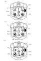
一方、一層さらなる発展型のリーチ演出(スペシャルリーチ演出と称しても差し支えない)が行われる場合には、引き続き、未だ変動中の中図柄列K2の図柄70A〜70Jを前記リスRCが必死になって止めようとするかの如く演出表示が行われるとともに、前記副表示部20bの逸脱表示領域CSに大勢のリス(以下、「リス群RCS」と称する)が表示されるとともに、該リス群RCSがあたかも家の窓から顔を覗かせているような表示制御が行われる。これを視認した遊技者は、主表示部20aでの最も興味深い演出のみならず、逸脱表示領域CSに表示されるリス群RCSに驚きを覚えるとともに、主表示部20aでの最もわくわくどきどきする演出及び逸脱表示領域CSでのさらなる期待感を高める演出に、今までにないような趣を覚える。そして、遊技者にとって最も好ましい事態(ここでは、大当たり状態の発生)が起こるのではないかという期待感が一層高められる。
On the other hand, when a further advanced type of reach production (which may be referred to as a special reach production) is performed, the squirrel RC continues to desperately continue the symbols 70A to 70J of the middle symbol row K2 that is still changing. In addition, an effect display is performed as if to stop, and a large number of squirrels (hereinafter referred to as “squirrel group RCS”) are displayed in the departure display area CS of the
次に、前記一匹のリスRCが移動してきたときと同様に、図9(a)に示すように、リス群RCSが移動するかのよう表示制御が行われる。より詳しくは、前記リス群RCSが家から飛び出し、それまで表示されていた副表示部20bの逸脱表示領域CSから主表示部20aへと連続的に移るかのような表示制御が行われる。また、この移動の一時期においては、副表示部20b(逸脱表示領域CS)及び主表示部20aの双方にリス群RCSの一部が表示されることとなる。つまり、リス群RCSのうち何匹かは表示され、残りの何匹かは主表示部20aに表示される。このような事象を視認した遊技者は、逸脱表示領域CSと主表示部20aとが関連づけられていることに再度驚きを覚えるとともに、より一層期待感が増すこととなる。
Next, as in the case where the single squirrel RC has moved, as shown in FIG. 9A, display control is performed as if the squirrel group RCS has moved. More specifically, display control is performed as if the squirrel group RCS jumped out of the house and moved continuously from the deviation display area CS of the
続いて、図9(b)に示すように、主表示部20aに表示されたリス群RCSが、それまで表示されていたリスRCとともに未だ変動中の中図柄列K2の図柄70A〜70Jを必死になって止めようとするかの如く演出表示が行われる。そして、その後、予め定められた図柄70A〜70Jにて、中図柄列K2が確定停止表示させられる。この場合、当該図柄70A〜70Jを外れ図柄で停止させることとしてもよいし、大当たり図柄で停止させることとしてもよい。但し、上記のようなリス群RCSによる演出が行われる場合には、大当たり図柄で停止される確率が一層高められるのが望ましい。
Subsequently, as shown in FIG. 9B, the squirrel group RCS displayed on the
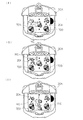
次に、図10〜図12に基づいて「ももんがリーチ」の演出表示態様について説明する。すなわち、前記図柄変動を行うべく表示制御基板110に対し出力されるコマンドに、「ももんがリーチ」演出を行う旨の情報が含まれていた場合において、表示制御基板110側で行われる処理内容について詳述する。この場合においても、上記同様、表示制御基板110のCPU63により、各図柄列K1〜K3の図柄70A〜70Jの変動が開始させられ、変動開始から所定時間経過後において、まずは左図柄列K1が所定の図柄70A〜70Jにて停止させられ、所定の大当たりラインL1〜L5上に右図柄列K2が前記左図柄列K1と同じ図柄70A〜70Jにて停止させられる。この時点(中図柄列K2は未だ変動中)で、リーチ状態が発生するのであるが、かかるタイミングにおいて、CPU63により、次のような制御が行われる。
Next, based on FIGS. 10 to 12, an effect display mode of “Monmon Reach” will be described. That is, in the case where the command output to the
すなわち、図10(a)に示すように、図示しない開閉部材用ソレノイドが制御されて開閉部材OPが開放させられる。これとともに、図10(b)に示すように、主表示部20aの上方から下方に向けて、かつ、画面奥部から画面手前側にももんがMCが飛来するかのような表示制御が行われる。これを視認した遊技者は、主表示部20aの図柄70A〜70J変動のみならず、開閉部材OPの開放に伴って表示されるももんがMCに驚きを覚えるとともに、開閉部材OPと主表示部20aとの相まった演出に今までにないような趣を覚える。そして、遊技者にとって好ましい事態(ここでは、さらなる発展型のリーチ演出、ひいては大当たり状態の発生)が起こるのではないかという期待感が高められる。
That is, as shown in FIG. 10A, an opening / closing member solenoid (not shown) is controlled to open the opening / closing member OP. At the same time, as shown in FIG. 10B, display control is performed as if Mon MC is flying from the top of the
主表示部20aに表示されたももんがMCは、主表示部20aの左上部か右下部のいずれかに移動表示制御され、この時点で開閉部材OPが閉鎖される。図10(c)に示すように、左上部にももんがMCが移動した場合には、次のような表示演出が行われる。すなわち、図11(a)に示すように、左上部に表示されていたももんがMCが高速変動中の中図柄列K2の所定の図柄70A〜70Iに飛び移るかの如く演出表示が行われる。この場合、さらなる発展型のリーチ演出が行われる場合と、そのまま中図柄列K2の図柄70A〜70Jが確定停止表示される場合とがある。そのまま中図柄列K2の図柄70A〜70Jが確定停止表示される場合には、当該図柄70A〜70Jを外れ図柄で停止させることとしてもよいし、大当たり図柄で停止させることとしてもよい。この場合において、その後ももんがMCは、例えば図11(b)に示すように、画面奥方へ飛んでいくかのように表示される。
The monkey MC displayed on the
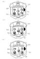
一方、さらなる発展型のリーチ演出が行われる場合には、ももんがMCが所定の図柄70A〜70Iに飛び移った後、図11(c)に示すように、一旦停止された中図柄列K2の図柄70A〜70Jが再度変動表示されるとともに、あたかもももんがMCが図柄70A〜70Jをよじ登っていくかのような演出表示が行われる。そして、その後、予め定められた図柄70A〜70Jにて、中図柄列K2が確定停止表示させられる。この場合、当該図柄70A〜70Jを外れ図柄で停止させることとしてもよいし、大当たり図柄で停止させることとしてもよい。但し、上記のような発展型の演出が行われる場合には、大当たり図柄で停止される確率が一層高められるのが望ましい。 On the other hand, in the case where a further development type of reach production is performed, after the monkey MC has jumped to the predetermined symbols 70A to 70I, as shown in FIG. 70A to 70J are displayed again and again, and an effect display is performed as if MC climbs the symbols 70A to 70J. After that, the middle symbol row K2 is displayed in a fixed stop manner with predetermined symbols 70A to 70J. In this case, the symbols 70 </ b> A to 70 </ b> J may be removed and stopped at the symbol, or may be stopped at the jackpot symbol. However, it is desirable that the probability of being stopped at the jackpot symbol is further increased when the above-described development type effect is performed.
また、図12(a)に示すように、右下部にももんがMCが移動した場合には、さらなる発展型のリーチ演出が行われる場合と、そのまま中図柄列K2の図柄70A〜70Jが確定停止表示される場合とがある。そのまま中図柄列K2の図柄70A〜70Jが確定停止表示される場合には、当該図柄70A〜70Jを外れ図柄で停止させることとしてもよいし、大当たり図柄で停止させることとしてもよいが、この場合においては、その後ももんがMCは、例えば図12(b)に示すように、画面奥方へ飛んでいくかのように表示される。 Also, as shown in FIG. 12 (a), when the mobile phone MC moves to the lower right corner, the symbols 70A to 70J in the middle symbol row K2 are displayed as fixed stop when the further reach type effect is performed. May be. When the symbols 70A to 70J in the middle symbol row K2 are displayed as fixed stop as they are, the symbols 70A to 70J may be removed and stopped at the symbol, or may be stopped at the jackpot symbol. In FIG. 12, after that, the MC is displayed as if it flies to the back of the screen, for example, as shown in FIG.
一方、さらなる発展型のリーチ演出が行われる場合には、図12(c)に示すように、大当たり図柄の3コマくらい手前の時点から、ももんがMCが図柄70A〜70Jを掴みにいき、その動作を1コマづつ繰り返すような演出表示が行われる。そして、その後、予め定められた図柄70A〜70Jにて、中図柄列K2が確定停止表示させられる。この場合、当該図柄70A〜70Jを外れ図柄で停止させることとしてもよいし、大当たり図柄で停止させることとしてもよい。但し、上記のような発展型の演出が行われる場合には、大当たり図柄で停止される確率が一層高められるのが望ましい。 On the other hand, when a more advanced reach production is performed, as shown in FIG. 12 (c), Monmon MC starts to grab the symbols 70A to 70J from about three frames before the jackpot symbol, and the operation An effect display that repeats the frame one frame at a time is performed. After that, the middle symbol row K2 is displayed in a fixed stop manner with predetermined symbols 70A to 70J. In this case, the symbols 70 </ b> A to 70 </ b> J may be removed and stopped at the symbol, or may be stopped at the jackpot symbol. However, it is desirable that the probability of being stopped at the jackpot symbol is further increased when the above-described development type effect is performed.
以上詳述したように、本実施の形態によれば、特別図柄表示装置20の表示画面20Bは主表示部20aと副表示部20bとを具備しており、主表示部20aにおいて背景及び大当たり状態を決定付ける図柄70A〜70Jが表示され、「リスリーチ」の演出が行われる場合に限って、主表示部20aの最大表示領域を超えて(逸脱して)、副表示部20b(逸脱表示領域CS)においてリスRC、リス群RCSが表示される。従って、遊技者は、基本的には図柄70A〜70Jの表示される主表示部20aでの表示演出を堪能することができるとともに、「リスリーチ」に際してはリスRC、リス群RCSの表示される副表示部20b(逸脱表示領域CS)における逸脱表示演出をも堪能することができる。そのため、遊技者は今までにはない面白味を覚え、結果的に興趣の飛躍的な向上を図ることができる。
As described above in detail, according to the present embodiment, the
特に、主表示部20aと逸脱表示領域CSとは互いに独立した存在であるため、両者20a,CSにおける表示に紛れが起こりにくく、該紛れによって遊技者が一方の表示を見損なってしまうといった不具合が起こりにくい。また、通常時は逸脱表示領域CSにおいてすら表示が行われないのであるが、それでも何ら違和感が生じない。
In particular, since the
また、逸脱表示領域CSに表示されるリスRC等と主表示部20aに表示されるリスRC等とが関連づけられているため、遊技者は今までにはない演出を堪能することができる。特に、副表示部20bの逸脱表示領域CSに表示されていたリスRC等が主表示部20aへと移動表示されるため、遊技者はかかる斬新な演出表示に驚きを覚え、かかる意味でより一層の興趣の向上を図ることができる。
Further, since the squirrel RC and the like displayed in the deviation display area CS and the squirrel RC and the like displayed on the
さらに、副表示部20b(逸脱表示領域CS)での表示によって主表示部20aでの表示が阻害されるわけではないので、主表示部20aでの表示(例えば図柄70A〜70Jや背景等の表示)の一部が割愛されてしまったり、制限を受けてしまったりすることがない。
Further, since the display on the
また、逸脱表示領域CSでの逸脱表示は、「リスリーチ」が演出表示される場合に限り許容されるため、かかる表示に稀少価値が付与され、遊技者は該表示をわくわくしながら堪能することができる。 In addition, since the deviation display in the deviation display area CS is allowed only when the “reach reach” is effected, a rare value is given to the display, and the player can enjoy the display while being excited. it can.
併せて、副表示部20aの非表示領域NSがセンタフレーム20Aで覆われているため、副表示部20bがセンターフレーム20Aに紛れやすくなり、副表示部20aが設けられていることによる全体としての違和感が払拭される。
In addition, since the non-display area NS of the
また、主表示部20a及び副表示部20bは、共に単一の表示制御基板110のCPU63によって表示制御されるため、制御手段たるCPUが増大してしまうことによる設置スペース増大というデメリット等を防止できる。また、上記のように主表示部20a及び逸脱表示領域CS双方で関連した演出表示を行う場合に、タイミングのズレ等が起こりにくく、演出効果が一層高められることとなる。
In addition, since both the
なお、本実施の形態の表示画面20Bは、主表示部20aと略相似関係にあるため、特別図柄表示装置20を別の遊技機の一部として再利用(リサイクル)したりする場合に、該表示装置20を、表示画面20B全体に識別情報の表示される(副表示部を有しない)タイプのものとして適用することもでき、かかる点でリサイクル性の向上を図ることが可能となる。
In addition, since the
尚、上記実施の形態の記載内容に限定されず、例えば次のように実施してもよい。 In addition, it is not limited to the description content of the said embodiment, For example, you may implement as follows.
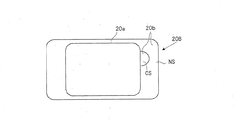
(a)上記実施の形態では、主表示部20aを表示画面20Bの中心位置に配置する構成となっているが、例えば図13(a)に示すように、主表示部20aを表示画面20Bに対し偏心位置(片寄った位置)に設けることとしてもよい。このように、偏心位置に主表示部20aを設けることで、副表示部20bのスペースに関し有効活用を図ることができる。
(A) In the above embodiment, the
(b)また、上記実施の形態では、主表示部20aに隣接して逸脱表示領域CSを配置することとしているが、同図に示すように、主表示部20aとは離間した位置に逸脱表示領域CSを配置することとしてもよい。このように逸脱表示領域CSを主表示部20aとは離間した位置に配置することで、主表示部20aと逸脱表示領域CSとの間での独立性を確保しやすい。また、このように独立性が確保されることで、両者20a,CSにおける表示に紛れが起こりにくく、該紛れによって遊技者が一方の表示を見損なってしまうといった不具合が起こりにくい。また、ある期間、一方の表示が行われないことがあったとしても違和感が生じない。
(B) In the above embodiment, the deviation display area CS is arranged adjacent to the
(c)上記実施の形態では、主表示部20aの上方及び下方に副表示部20b(非表示領域NS)が存在するよう構成されているが、図13(b)に示すように、表示画面20Bの一方の側(図の左側)を主表示部20a、他方の側(図の右側)を副表示部20bとし、主表示部20aの上下両側には副表示部20bの存在しない構成としてもよい。さらには、図13(c)に示すように、単純に仕切線SLで表示画面20Bを区別するだけの構成としてもよい。併せて、副表示部20bの全てを表示可能領域とし(非表示領域を設けない構成とし)てもよい。
(C) In the above embodiment, the
(d)上記実施の形態では、副表示部20bの一方の側(図の右側)にのみ逸脱表示領域CSを配置する構成としているが、図13(d)に示すように、左右両側に逸脱表示領域CSを(複数)配置する構成としてもよい。
(D) In the above embodiment, the deviation display area CS is arranged only on one side (right side in the figure) of the
(e)上記実施の形態では非表示領域NSを真っ黒にしか表示されない構成としているが、何らかの模様(例えば木目模様等)が表示されることとしてもよい。この場合において、非表示領域NSの一部がセンターフレーム20Aで覆われており、残りの部分が露出している構成の場合には、露出部分がセンターフレーム20Aと同様木目模様が付されることで両者が渾然一体化され、違和感を生じにくくすることができる。
(E) In the above embodiment, the non-display area NS is configured to be displayed only in black, but some pattern (for example, a wood grain pattern) may be displayed. In this case, when the non-display area NS is partly covered with the
また、非表示領域NSの少なくとも一部が露出されるような場合には、常時一定の態様を呈さなくてもよく、例えばセンターフレーム20Aに設けられたランプ等の発光態様(色調)に合わせて、非表示領域の色調を変化させるような演出を行ってもよい。
In addition, when at least a part of the non-display area NS is exposed, it does not always have to have a certain form, for example, according to a light emitting form (color tone) such as a lamp provided in the
(f)上記実施の形態では特に言及していないが、副表示部20bに対応する部分のセンターフレーム20Aにおいて遊技球Bが通過可能な構成となっていてもよい。例えば、副表示部20bのうち両側部分に対応するセンターフレーム20A部分に遊技球通路を設けることとしてもよい。この場合、遊技球通路と逸脱表示領域CSとが相まって、今までにはない外観を呈し、しかも、リスRC等の表示対象の表示と、遊技球Bの通過といった各事象を1つの部位において堪能できる。
(F) Although not particularly mentioned in the above embodiment, the game ball B may pass through the
(g)主表示部20aにおける表示制御と逸脱表示領域CSにおける表示制御とを互いに異なる表示制御手段(CPU)で行うこととしてもよい。
(G) The display control in the
(h)上記実施の形態では、逸脱表示領域CSに表示対象としてリスRCを表示することとしているが、リスRC等のキャラクタの代わりに別の表示対象(例えばリーチ状態や大当たり状態の発生を示唆する文字、図形、或いは大当たり状態中のラウンド数や入賞個数等)を表示することとしてもよい。また、場合によっては逸脱表示領域CSに図柄が表示されることがあってもよい。逆に、逸脱表示領域CSには図柄が一切表示されないこととしてもよい。 (H) In the above embodiment, the squirrel RC is displayed as the display object in the departure display area CS, but instead of a character such as the squirrel RC, another display object (for example, a reach state or a jackpot state is suggested) Or the like, the number of rounds or the number of winning prizes in the big hit state, etc.) may be displayed. In some cases, symbols may be displayed in the deviation display area CS. Conversely, no symbols may be displayed in the deviation display area CS.
(i)上記実施の形態のような5ラインタイプのものでなくてもよい。例えば、いわゆる2ラインタイプ(例えば上下の横方向の大当たりラインがあるもの)や、3ラインタイプ(例えば上中下の横方向の大当たりラインがあるもの)のパチンコ機であってもよい。 (I) It does not have to be of the 5-line type as in the above embodiment. For example, a so-called two-line type (for example, one having upper and lower horizontal jackpot lines) or three-line type (for example, one having upper, middle and lower horizontal jackpot lines) may be used.
(j)特別図柄表示装置20としては、上述した液晶ディスプレイ以外にも、CRT、ドットマトリックス、LED、エレクトロルミネセンス(EL)、蛍光表示管等を用いてもよい。
(J) As the special
(k)上記実施の形態とは異なるタイプのパチンコ機等にも適用できる。例えば、大当たり図柄が表示された後に所定の領域に遊技球を入賞させることを必要条件として特別遊技状態となるパチンコ機として実施してもよい。また、表示部のないパチンコ機(例えば大羽根等の変動入賞装置やクルーンといった役物が搭載されているタイプや、いわゆる多くのチューリップが搭載されているタイプ等)にも応用できる。また、パチンコ機以外にも、アレパチ、雀球、スロットマシン、パチンコ機とスロットマシンとが融合した遊技機等の各種遊技機として実施することも可能である。なお、スロットマシンは、例えばコインを投入して図柄有効ラインを決定させた状態で操作レバーを操作することにより図柄が変動され、ストップボタンを操作することにより図柄が停止されて確定される周知のものである。この場合、遊技媒体はコイン、メダル等が代表例として挙げられる。 (K) The present invention can also be applied to a pachinko machine of a type different from the above embodiment. For example, it may be implemented as a pachinko machine that is in a special gaming state under the condition that a game ball is awarded in a predetermined area after a jackpot symbol is displayed. Further, it can be applied to a pachinko machine without a display unit (for example, a type in which a variable prize device such as a large feather or an accessory such as a croon is mounted, or a type in which many so-called tulips are mounted). In addition to pachinko machines, the present invention can also be implemented as various game machines such as alepatches, sparrow balls, slot machines, and game machines in which pachinko machines and slot machines are integrated. In the slot machine, for example, a symbol is changed by operating a control lever in a state where a symbol effective line is determined by inserting coins, and a symbol is stopped and confirmed by operating a stop button. Is. In this case, examples of the game media include coins and medals.
また、パチンコ機とスロットマシンとが融合した遊技機の具体例としては、複数の図柄からなる図柄列を変動表示した後に図柄を確定表示する可変表示手段を備えており、遊技球打出用のハンドルを備えていないものが挙げられる。この場合、所定の操作(ボタン操作)に基づく、所定量の遊技球の投入の後、例えば操作レバーの操作に起因して図柄の変動が開始され、例えばストップボタンの操作に起因して或いは所定時間経過することにより図柄の変動が停止され、その停止時の確定図柄がいわゆる大当たり図柄であることを必要条件として遊技者に有利な大当たり状態が発生させられ、遊技者には、下部の受皿に多量の遊技球が払い出されるものである。 In addition, as a specific example of a gaming machine in which a pachinko machine and a slot machine are integrated, a variable ball display unit is provided which includes a variable display means for confirming and displaying a symbol after a symbol string composed of a plurality of symbols is variably displayed. The thing which is not equipped with is mentioned. In this case, after throwing a predetermined amount of game balls based on a predetermined operation (button operation), for example, the variation of the symbol is started due to an operation of an operation lever, for example, due to an operation of a stop button or a predetermined amount As time passes, the fluctuation of the symbol is stopped, and the jackpot state that is advantageous to the player is generated on the condition that the confirmed symbol at the time of stoppage is a so-called jackpot symbol. A large amount of game balls are paid out.
(l)上記実施の形態では、図柄列として、左・中・右の3つの図柄列K1,K2,K3を採用しているが、2つ以下、或いは4つ以上の図柄列により構成してもよい。また、停止順序も上記実施の形態のものに何ら限定されるものではない。 (L) In the above embodiment, three symbol rows K1, K2, and K3 of the left, middle, and right are employed as the symbol rows. However, the symbol rows are constituted by two or less symbol rows or four or more symbol rows. Also good. Also, the stop order is not limited to that of the above embodiment.
(m)上記実施の形態では、リスRC等が副表示部20bの逸脱表示領域CSからから主表示部20aへと連続的に移動するかのような表示が行われるが、瞬間的な移動であってもよいし、同時に同一又は同種の表示対象を両者CS,20aに表示してもよい。また、表示対象の表示タイミングは、リーチ状態中に限られず、リーチ状態発生前に表示してもよいし、大当たり中に表示してもよい。なお、リーチ状態前に表示する場合には、リーチ予告或いは大当たり予告等の一環として表示することが望ましい。
(M) In the above embodiment, the display is performed as if the squirrel RC or the like continuously moves from the deviation display area CS of the
(n)主表示部20aに表示されていた図柄やその他の表示客体が逸脱表示領域CSへと移動表示されるようにしてもよい。
(N) The symbols and other display objects displayed on the
1…パチンコ機、8…遊技盤、11…作動口、12…大入賞口、20…可変表示装置としての特別図柄表示装置、20A…フレーム部材としてのセンターフレーム、20B…表示画面、20a…表示部としての主表示部、20b…副表示部、50…主基板、63…表示制御基板のCPU、110…表示制御基板、K1…左図柄列、K2…中図柄列、K3…右図柄列、B…遊技媒体としての遊技球、RC…表示対象としてのリス、MC…ももんが、CS…逸脱表示領域、NS…非表示領域。
DESCRIPTION OF
Claims (1)
該検出手段で前記始動条件の発生が検出された場合に、当否を抽選する抽選手段と、
前記検出手段で前記始動条件の発生が検出された場合に、前記抽選手段の当否抽選の結果に応じた演出が実行される可変演出手段と、
該可変演出手段を制御する制御手段と、を備えた遊技機であって、
前記可変演出手段は、
前記検出手段で前記始動条件の発生が検出された場合に識別情報が変動表示される可変表示部と、
該可変表示部の周囲を囲うフレーム部と、
前記可変表示部の表示面側に設けられる演出部と、を備え、
該演出部は、
前記可変表示部に表示される画像を視認可能な窓部を有し、所定の装飾が付され、前記可変表示部の表示面の一部の前面側に重なる第1演出部を備え、
前記制御手段は、
前記窓部を介することなく視認可能に表示される第1表示領域と、前記窓部を介して視認可能に表示される第2表示領域と、を有する前記可変表示部を表示制御する機能と、
前記窓部に対応する前記第2表示領域に、前記識別情報と異なり、前記所定の装飾に応じた装飾用背景画像を表示する機能と、
前記窓部に対応する前記第2表示領域に、前記識別情報と異なるキャラクタ画像を含む画像を表示する機能と、を備え、
前記演出部は更に、遊技機正面視における前記可変表示部の中心よりも端側である第1位置と、その第1位置よりも前記可変表示部の中心側である第2位置との間で位置が切替えられるよう前記制御手段によって制御される第2演出部を備え、
前記制御手段は、前記第2演出部を前記第2位置に位置させる場合に、前記第1表示領域に、前記第2演出部の動作に対応した動作演出時画像を表示するものであり、
前記視認部に対応する前記第2表示領域は、前記第1演出部によって前記第1表示領域と区画され、
さらに、前記制御手段は、前記キャラクタ画像を、前記第1表示領域と前記第2表示領域とに同時に表示する機能を備えていることを特徴とする遊技機。 Detection means for detecting the occurrence of a start condition;
Lottery means for lottery determination when the detection means detects the occurrence of the start condition;
When the detection means detects the occurrence of the starting condition, variable effect means for executing an effect according to the result of the lottery means's success / failure lottery,
A control means for controlling the variable effect means,
The variable rendering means is
A variable display unit in which identification information is variably displayed when occurrence of the start condition is detected by the detection means;
A frame portion surrounding the variable display portion;
An effect unit provided on the display surface side of the variable display unit,
The production section
A window that allows the image displayed on the variable display unit to be visually recognized, is provided with a predetermined decoration, and includes a first effect unit that overlaps a part of the front surface of the display surface of the variable display unit;
The control means includes
A function of controlling display of the variable display unit, the first display region being displayed so as to be visible without passing through the window, and the second display region being displayed so as to be visible through the window;
Unlike the identification information, in the second display area corresponding to the window, a function of displaying a decorative background image corresponding to the predetermined decoration;
A function of displaying an image including a character image different from the identification information in the second display area corresponding to the window,
The rendering unit is further between a first position that is closer to the end than the center of the variable display unit in a front view of the gaming machine and a second position that is closer to the center of the variable display unit than the first position. A second rendering unit controlled by the control means so that the position is switched;
The control means is for displaying an image during operation effect corresponding to the operation of the second effect unit in the first display area when the second effect unit is positioned at the second position.
The second display area corresponding to the visual recognition part is partitioned from the first display area by the first effect part,
Furthermore, the control means has a function of displaying the character image in the first display area and the second display area at the same time .
Priority Applications (1)
| Application Number | Priority Date | Filing Date | Title |
|---|---|---|---|
| JP2012088138A JP5516632B2 (en) | 2012-04-09 | 2012-04-09 | Game machine |
Applications Claiming Priority (1)
| Application Number | Priority Date | Filing Date | Title |
|---|---|---|---|
| JP2012088138A JP5516632B2 (en) | 2012-04-09 | 2012-04-09 | Game machine |
Related Parent Applications (1)
| Application Number | Title | Priority Date | Filing Date |
|---|---|---|---|
| JP2011011078A Division JP2011072849A (en) | 2011-01-21 | 2011-01-21 | Game machine |
Publications (2)
| Publication Number | Publication Date |
|---|---|
| JP2012152579A JP2012152579A (en) | 2012-08-16 |
| JP5516632B2 true JP5516632B2 (en) | 2014-06-11 |
Family
ID=46834928
Family Applications (1)
| Application Number | Title | Priority Date | Filing Date |
|---|---|---|---|
| JP2012088138A Expired - Lifetime JP5516632B2 (en) | 2012-04-09 | 2012-04-09 | Game machine |
Country Status (1)
| Country | Link |
|---|---|
| JP (1) | JP5516632B2 (en) |
Family Cites Families (1)
| Publication number | Priority date | Publication date | Assignee | Title |
|---|---|---|---|---|
| JP2000342791A (en) * | 1999-06-09 | 2000-12-12 | Daiichi Shokai Co Ltd | Gaming machine display |
-
2012
- 2012-04-09 JP JP2012088138A patent/JP5516632B2/en not_active Expired - Lifetime
Also Published As
| Publication number | Publication date |
|---|---|
| JP2012152579A (en) | 2012-08-16 |
Similar Documents
| Publication | Publication Date | Title |
|---|---|---|
| JP5076259B2 (en) | Game machine | |
| JP4644937B2 (en) | Game machine | |
| JP5083378B2 (en) | Game machine | |
| JP2009273913A (en) | Game machine | |
| JP5516631B2 (en) | Game machine | |
| JP4400016B2 (en) | Game machine | |
| JP2009000575A (en) | Game machine | |
| JP2011072850A (en) | Game machine | |
| JP4826045B2 (en) | Game machine | |
| JP4086100B2 (en) | Game machine | |
| JP5516632B2 (en) | Game machine | |
| JP4826044B2 (en) | Game machine | |
| JP5516633B2 (en) | Game machine | |
| JP4400691B2 (en) | Game machine | |
| JP4400692B2 (en) | Game machine | |
| JP5202779B2 (en) | Game machine | |
| JP5754521B2 (en) | Game machine | |
| JP4826047B2 (en) | Game machine | |
| JP4826046B2 (en) | Game machine | |
| JP5212496B2 (en) | Game machine | |
| JP5370533B2 (en) | Game machine | |
| JP4134818B2 (en) | Game machine | |
| JP2011072849A (en) | Game machine | |
| JP5327242B2 (en) | Game machine | |
| JP2009112859A (en) | Game machine |
Legal Events
| Date | Code | Title | Description |
|---|---|---|---|
| A621 | Written request for application examination |
Free format text: JAPANESE INTERMEDIATE CODE: A621 Effective date: 20120508 |
|
| A131 | Notification of reasons for refusal |
Free format text: JAPANESE INTERMEDIATE CODE: A131 Effective date: 20130723 |
|
| A521 | Request for written amendment filed |
Free format text: JAPANESE INTERMEDIATE CODE: A523 Effective date: 20130924 |
|
| TRDD | Decision of grant or rejection written | ||
| A01 | Written decision to grant a patent or to grant a registration (utility model) |
Free format text: JAPANESE INTERMEDIATE CODE: A01 Effective date: 20140304 |
|
| A61 | First payment of annual fees (during grant procedure) |
Free format text: JAPANESE INTERMEDIATE CODE: A61 Effective date: 20140317 |
|
| R150 | Certificate of patent or registration of utility model |
Ref document number: 5516632 Country of ref document: JP Free format text: JAPANESE INTERMEDIATE CODE: R150 |
|
| R250 | Receipt of annual fees |
Free format text: JAPANESE INTERMEDIATE CODE: R250 |
|
| R250 | Receipt of annual fees |
Free format text: JAPANESE INTERMEDIATE CODE: R250 |
|
| R250 | Receipt of annual fees |
Free format text: JAPANESE INTERMEDIATE CODE: R250 |
|
| R250 | Receipt of annual fees |
Free format text: JAPANESE INTERMEDIATE CODE: R250 |