JP5516168B2 - projector - Google Patents
projector Download PDFInfo
- Publication number
- JP5516168B2 JP5516168B2 JP2010159511A JP2010159511A JP5516168B2 JP 5516168 B2 JP5516168 B2 JP 5516168B2 JP 2010159511 A JP2010159511 A JP 2010159511A JP 2010159511 A JP2010159511 A JP 2010159511A JP 5516168 B2 JP5516168 B2 JP 5516168B2
- Authority
- JP
- Japan
- Prior art keywords
- light
- modulation device
- light modulation
- fixing member
- projector
- Prior art date
- Legal status (The legal status is an assumption and is not a legal conclusion. Google has not performed a legal analysis and makes no representation as to the accuracy of the status listed.)
- Expired - Fee Related
Links
Images


Classifications
-
- G—PHYSICS
- G03—PHOTOGRAPHY; CINEMATOGRAPHY; ANALOGOUS TECHNIQUES USING WAVES OTHER THAN OPTICAL WAVES; ELECTROGRAPHY; HOLOGRAPHY
- G03B—APPARATUS OR ARRANGEMENTS FOR TAKING PHOTOGRAPHS OR FOR PROJECTING OR VIEWING THEM; APPARATUS OR ARRANGEMENTS EMPLOYING ANALOGOUS TECHNIQUES USING WAVES OTHER THAN OPTICAL WAVES; ACCESSORIES THEREFOR
- G03B21/00—Projectors or projection-type viewers; Accessories therefor
- G03B21/14—Details
- G03B21/16—Cooling; Preventing overheating
-
- H—ELECTRICITY
- H04—ELECTRIC COMMUNICATION TECHNIQUE
- H04N—PICTORIAL COMMUNICATION, e.g. TELEVISION
- H04N9/00—Details of colour television systems
- H04N9/12—Picture reproducers
- H04N9/31—Projection devices for colour picture display, e.g. using electronic spatial light modulators [ESLM]
- H04N9/3102—Projection devices for colour picture display, e.g. using electronic spatial light modulators [ESLM] using two-dimensional electronic spatial light modulators
- H04N9/3105—Projection devices for colour picture display, e.g. using electronic spatial light modulators [ESLM] using two-dimensional electronic spatial light modulators for displaying all colours simultaneously, e.g. by using two or more electronic spatial light modulators
-
- H—ELECTRICITY
- H04—ELECTRIC COMMUNICATION TECHNIQUE
- H04N—PICTORIAL COMMUNICATION, e.g. TELEVISION
- H04N9/00—Details of colour television systems
- H04N9/12—Picture reproducers
- H04N9/31—Projection devices for colour picture display, e.g. using electronic spatial light modulators [ESLM]
- H04N9/3141—Constructional details thereof
Landscapes
- Engineering & Computer Science (AREA)
- Multimedia (AREA)
- Signal Processing (AREA)
- Physics & Mathematics (AREA)
- General Physics & Mathematics (AREA)
- Liquid Crystal (AREA)
- Projection Apparatus (AREA)
- Video Image Reproduction Devices For Color Tv Systems (AREA)
Description
本発明は、プロジェクターに関する。 The present invention relates to a projector.
従来、R(赤),G(緑),B(青)の3つの色光を3枚の液晶パネル(光変調装置)にてそれぞれ変調し、変調後の各色光をクロスダイクロイックプリズム(色合成光学装置)にて合成してスクリーンに向けて投射するプロジェクターが知られている。
このようなプロジェクターでは、色合成光学装置に対して光変調装置を一体に組み付けて、組立性の向上を図っている(例えば、特許文献1参照)。
特許文献1に記載のプロジェクターでは、色合成光学装置に対して光変調装置を固定する部材として、光を通過させる開口部を有する板状の固定部材と、色合成光学装置の光入射面に固定され、固定部材を支持する支持部材とが設けられている。
そして、光変調装置は、開口部を閉塞するように固定部材における光入射側の板面に対してネジにより固定されている。
Conventionally, three color lights of R (red), G (green), and B (blue) are each modulated by three liquid crystal panels (light modulation devices), and each color light after modulation is cross-dichroic prism (color synthesis optics). A projector that synthesizes and projects the image onto a screen is known.
In such a projector, the light modulation device is integrally assembled with the color synthesizing optical device to improve assemblability (see, for example, Patent Document 1).
In the projector described in
The light modulation device is fixed with screws to the light incident side plate surface of the fixing member so as to close the opening.
しかしながら、特許文献1に記載のプロジェクターでは、光変調装置を冷却するために、固定部材の板面に平行となる方向から光変調装置に空気を送風しても、光変調装置を効果的に冷却することが難しい、という問題がある。
具体的に、送風された空気は、光変調装置の光入射側及び光出射側に分流される。
そして、光変調装置の光入射側に分流された空気は、光変調装置における光入射側の端部に沿って流通し、光変調装置の光入射側を冷却する。
一方、光変調装置の光出射側に分流された空気は、固定部材における光出射側の板面に沿って流通することとなる。すなわち、固定部材の厚み分、光変調装置における光出射側の端部が光入射側にオフセットした位置に位置付けられているため、固定部材における光出射側の板面に沿って空気が流通しても、光変調装置における光出射側の端部に効果的に空気が送風されないこととなる。
したがって、光変調装置における光入射側の端部、及び光出射側の端部の双方に効果的に空気を送風することができず、光変調装置を効果的に冷却することが難しい。
However, in the projector described in
Specifically, the blown air is diverted to the light incident side and the light emitting side of the light modulation device.
Then, the air diverted to the light incident side of the light modulation device flows along the light incident side end of the light modulation device, and cools the light incident side of the light modulation device.
On the other hand, the air diverted to the light emitting side of the light modulation device flows along the plate surface on the light emitting side of the fixing member. That is, because the end of the light emitting side of the light modulation device is offset by the thickness of the fixing member, the air flows along the plate surface of the fixing member on the light emitting side. In addition, air is not effectively blown to the light emitting side end of the light modulation device.
Therefore, air cannot be effectively blown to both the light incident side end and the light emission side end of the light modulation device, and it is difficult to effectively cool the light modulation device.
本発明の目的は、光変調装置を効果的に冷却できるプロジェクターを提供することにある。 An object of the present invention is to provide a projector capable of effectively cooling a light modulation device.
本発明のプロジェクターは、複数の色光を色光毎に変調する複数の光変調装置と、前記各光変調装置にそれぞれ対向する複数の光入射面を有し前記複数の光変調装置にて変調された各色光を合成する色合成光学装置とを備えたプロジェクターであって、開口部が形成された板状の基体を有し、前記光変調装置を前記色合成光学装置に対して固定するための固定部材を備え、前記光変調装置は、前記開口部に挿入され、前記光変調装置における光入射側及び光出射側の各端部が前記基体の板面からそれぞれ突出した状態で前記固定部材に固定されることを特徴とする。 The projector according to the present invention includes a plurality of light modulation devices that modulate a plurality of color lights for each color light, and a plurality of light incident surfaces that face the light modulation devices, respectively, and are modulated by the plurality of light modulation devices. A projector comprising a color synthesis optical device for synthesizing each color light, having a plate-like base with an opening formed therein, and fixing for fixing the light modulation device to the color synthesis optical device The light modulation device is inserted into the opening, and fixed to the fixing member in a state where each end of the light incident side and light emission side of the light modulation device protrudes from the plate surface of the base body. It is characterized by being.
本発明では、光変調装置は、上述したように固定部材に対して固定される。
このことにより、固定部材における基体の板面に平行となる方向から光変調装置に空気を送風した場合に、光変調装置の光入射側及び光出射側に分流された空気は、基体の板面から突出した光変調装置における光入射側及び光出射側の各端部に送風されることとなる。
したがって、固定部材により光変調装置における光入射側及び光出射側の各端部への送風量が制限されることがなく、光変調装置を効果的に冷却できる。
In the present invention, the light modulation device is fixed to the fixing member as described above.
Thus, when air is blown to the light modulation device from the direction parallel to the plate surface of the base member in the fixing member, the air diverted to the light incident side and the light emission side of the light modulation device is the plate surface of the base member. The light is blown to the light incident side and light emission side end portions of the light modulation device projecting from.
Therefore, the amount of air blown to the light incident side and light exit side ends of the light modulation device is not limited by the fixing member, and the light modulation device can be effectively cooled.
また、光変調装置は、固定部材の開口部に挿入された状態であるため、固定部材との接触面積(光変調装置の側端部と開口部の縁との接触面積)を大きくとることができる。このため、固定部材を金属等の熱伝導性の高い材料で構成すれば、光変調装置から固定部材に熱を効果的に伝達させることができ、光変調装置をさらに効果的に冷却できる。 In addition, since the light modulation device is inserted into the opening of the fixing member, the contact area with the fixing member (contact area between the side end of the light modulation device and the edge of the opening) can be increased. it can. Therefore, if the fixing member is made of a material having high thermal conductivity such as metal, heat can be effectively transmitted from the light modulation device to the fixing member, and the light modulation device can be further effectively cooled.
本発明のプロジェクターでは、前記固定部材は、前記基体における互いに対向する一対の端縁から前記基体の面外方向にそれぞれ起立する一対の起立部を備え、前記一対の起立部は、他方の前記起立部に向けて延出する延出部をそれぞれ備え、前記光変調装置は、前記光入射側の端部または前記光出射側の端部が前記延出部に固定されることが好ましい。
本発明では、光変調装置が上述した延出部に固定されるので、固定部材の開口部に挿入されながら安定して光変調装置を固定部材に固定することができる。
In the projector according to the aspect of the invention, the fixing member includes a pair of upright portions that stand up in a direction out of the plane of the base from a pair of opposite edges of the base, and the pair of uprights is the other of the standups. It is preferable that each of the light modulation devices includes an extension portion extending toward the portion, and an end portion on the light incident side or an end portion on the light emission side is fixed to the extension portion.
In the present invention, since the light modulation device is fixed to the extending portion described above, the light modulation device can be stably fixed to the fixing member while being inserted into the opening of the fixing member.
以下、本発明の実施の一形態を図面に基づいて説明する。
〔プロジェクターの構成〕
図1は、プロジェクター1の概略構成を示す図である。具体的に、図1は、本願の要部である投射ユニット2の光学系を模式的に示した平面図である。
プロジェクター1は、画像を投射してスクリーン(図示略)上に投影画像を表示する。
このプロジェクター1は、図1に示すように、外装筐体(図示略)内部に収納される投射ユニット2及び冷却装置(図示略)等を備える。
投射ユニット2は、光源装置(図示略)から出射され、ダイクロイックミラー等の色分離光学装置(図示略)で分離されたR(赤),G(緑),B(青)の各色光をそれぞれ変調し、変調した各色光を合成して投射するものである。
この投射ユニット2は、図1に示すように、投射光学装置としての投射レンズ3と、光学装置4とを備える。
Hereinafter, an embodiment of the present invention will be described with reference to the drawings.
[Configuration of projector]
FIG. 1 is a diagram illustrating a schematic configuration of the
The
As shown in FIG. 1, the
The
As shown in FIG. 1, the
〔光学装置の構成〕
図2は、光学装置4の構成を示す斜視図である。具体的に、図2は、光学装置4を投射方向とは反対側から見た斜視図である。
なお、図2では、説明の便宜上、3つの入射側偏光板6の図示を省略している。
光学装置4は、図1または図2に示すように、3つの光変調装置5と、3つの入射側偏光板6(図1)と、3つの出射側偏光板7(図1)と、色合成光学装置としてのクロスダイクロイックプリズム8と、3つの支持部材9(図2)と、3つの固定部材10(図2)とを備える。
[Configuration of optical device]
FIG. 2 is a perspective view showing the configuration of the optical device 4. Specifically, FIG. 2 is a perspective view of the optical device 4 viewed from the side opposite to the projection direction.
In FIG. 2, for convenience of explanation, the illustration of the three incident side polarizing
As shown in FIG. 1 or FIG. 2, the optical device 4 includes three
〔入射側偏光板の構成〕
3つの入射側偏光板6は、同様に構成されたものであり、図1に示すように、光学装置4において、R,G,Bの各色光の光入射側にそれぞれ配設される。そして、入射側偏光板6は、入射した色光のうち、所定の直線偏光光のみを透過する。
[Configuration of the polarizing plate on the incident side]
The three incident-side polarizing
〔光変調装置の構成〕
3つの光変調装置5は、同様に構成されたものであり、図1に示すように、各入射側偏光板6の光出射側にそれぞれ配設される。
この光変調装置5は、図2に示すように、液晶パネル51と、パネル保持枠52とを備える。
液晶パネル51は、具体的な図示は省略したが、一対の透明なガラス基板に電気光学物質である液晶が密閉封入された構成を有する。そして、液晶パネル51は、制御装置(図示略)からの駆動信号に応じて、前記液晶の配向状態が制御され、入射側偏光板6から出射された直線偏光光の偏光方向を変調する。
[Configuration of light modulator]
The three
As shown in FIG. 2, the
Although not specifically illustrated, the
なお、液晶パネル51の光入射側及び光出射側には、一対の防塵ガラス51A,51B(図5、図6参照)が取り付けられている。
これら一対の防塵ガラス51A,51Bは、熱伝導性の高い材料、例えば水晶等の透光性基板で構成されている。
本実施形態では、防塵ガラス51A,51Bとして、従来用いられていた防塵ガラスに対して平面形状が略20%程度、大きいものを採用している。
A pair of
The pair of
In the present embodiment, as the dust-
パネル保持枠52は、金属等の熱伝導性材料から構成され、液晶パネル51が収納される部材である。
このパネル保持枠52は、図2に示すように、本体521と、規制板522とを備える。
本体521は、規制板522に対して光出射側に配設され、平面視略矩形形状を有する。
この本体521は、具体的な図示は省略したが、光入射側において、液晶パネル51の外形形状に対応し光出射側に窪む収納凹部が形成されている。
そして、液晶パネル51は、前記収納凹部に遊嵌状態で収納される。
また、前記収納凹部の底部分には、液晶パネル51の画像形成領域に対応した開口部521A(図6参照)が形成されている。
さらに、本体521には、前記収納凹部を囲むように、4つの固定用孔521Bが形成されている。
The
As shown in FIG. 2, the
The
Although not specifically shown, the
The
Further, an
Further, four fixing
規制板522は、図2に示すように、平面視略中央部分に液晶パネル51の画像形成領域に対応した開口部522Aを有する矩形状の板体から構成される。そして、規制板522は、本体521の光入射側に取り付けられることで、前記収納凹部から光入射側への液晶パネル51の移動を規制する。
上述した規制板522は、高反射性を有する材料で構成されている。そして、規制板522は、光変調装置5に向けて照射される色光のうち、画像形成領域(開口部522A)から外れた色光を反射する。このように規制板522にて上述した色光を反射することで、光の照射による光変調装置5の温度上昇を回避している。
なお、規制板522としては、高反射性を有する材料で構成する他、光入射側の端面に金属等の反射膜を形成した構成を採用しても構わない。
As shown in FIG. 2, the
The
The
〔出射側偏光板の構成〕
3つの出射側偏光板7は、同様に構成されたものであり、図1に示すように、各光変調装置5とプリズム8との間にそれぞれ配設される。この出射側偏光板7は、図1に示すように、光入射側に配置される第1偏光板71と、光出射側に配置される第2偏光板72の2体で構成される。
各偏光板71,72は、入射側偏光板6と同様の構成であり、入射した色光のうち、所定の直線偏光光のみを透過する。
なお、各偏光板71,72は、透過軸が互いに略平行となるように配置されるとともに、入射側偏光板6の透過軸と略直交するように配置される。
[Configuration of output-side polarizing plate]
The three exit-side
Each of the
Each of the
〔クロスダイクロイックプリズムの構成〕
プリズム8は、図1または図2に示すように、各出射側偏光板7を透過した各色光がそれぞれ入射される3つの光入射面81を有し、入射した各色光を合成する。
このプリズム8は、4つの直角プリズムを貼り合せた平面視略正方形状をなし、直角プリズム同士を貼り合せた界面には、2つの誘電体多層膜が形成されている。これら誘電体多層膜は、G色光側の出射側偏光板7(7G(図1))を介したG色光を透過し、R,B色光側の各出射側偏光板7(7R,7B(図1))を介したR,B色光をそれぞれ反射する。このようにして、各色光が合成される。そして、プリズム8で合成された光束(画像)は、投射レンズ3にてスクリーンに投射される。
[Configuration of cross dichroic prism]
As shown in FIG. 1 or FIG. 2, the
This
〔支持部材の構成〕
3つの支持部材9は、同様に構成されたものであり、熱伝導性の高い材料、例えば水晶等の透光性基板8A(図2)を介してプリズム8の各光入射面81にそれぞれ固定される。そして、支持部材9は、光変調装置5、出射側偏光板7及び固定部材10を保持する。
この支持部材9は、図2に示すように、金属製の板体に板金加工を施すことにより形成されたものであり、板状部91と、4つのピン92とを備える。
板状部91は、透光性基板8Aに接着剤等により固定される部分であり、具体的な図示は省略したが、略中央部分に矩形状の開口部(図示略)を有する平面視略矩形板状に形成されている。
そして、第2偏光板72は、板状部91における光入射側の端面に接着剤等により固定される。
(Configuration of support member)
The three
As shown in FIG. 2, the
The plate-
The second
4つのピン92は、板状部91の四隅角部分から光入射側に突出する。
4つのピン92のうち、図2中、上方側に位置する2つのピン92Uは、図2中、上下方向に沿う軸を折り曲げ軸として折り曲げられることで光入射側に突出するように形成されている。
また、図2中、下方側に位置する2つのピン92Dは、図2中、左右方向に沿う軸を折り曲げ軸として折り曲げられることで光入射側に突出するように形成されている。
The four
Of the four
Also, the two
〔固定部材の構成〕
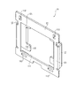
図3及び図4は、固定部材10の構成を示す斜視図である。具体的に、図3は固定部材10を光入射側から見た斜視図であり、図4は固定部材10を光出射側から見た斜視図である。
固定部材10は、第1偏光板71及び光変調装置5を一体化し、支持部材9を介してプリズム8の光入射面81に固定するための部材である。
この固定部材10は、支持部材9と同様に、金属製の板体に板金加工を施すことにより形成されたものであり、図3または図4に示すように、基体11と、一対の起立部12とを備える。
本実施形態では、固定部材10の表面には、反射防止処理が施されているものである。
[Configuration of fixing member]
3 and 4 are perspective views showing the configuration of the fixing
The fixing
Like the
In the present embodiment, the surface of the fixing
基体11は、図3または図4に示すように、略中央部分に光変調装置5の平面形状に対応した矩形状の開口部111を有する平面視略矩形板状に形成されている。
この基体11において、四隅角部分には、挿通用孔112がそれぞれ形成されている。
そして、固定部材10は、図2に示すように、支持部材9における4つのピン92が各挿通用孔112に挿通することで、支持部材9に支持される。
As shown in FIG. 3 or FIG. 4, the
In the
As shown in FIG. 2, the fixing
一対の起立部12は、基体11における互いに対向する一対の端縁(図3、図4中、左右方向の端縁)から光出射側(基体11における板面の面外方向)に起立する。
これら一対の起立部12は、図3または図4に示すように、上下方向に沿う軸を折り曲げ軸として2箇所、折り曲げられたものである。
そして、一対の起立部12は、延出部としての各先端部分121が他方に向けて延出し(互いに近接し)、かつ、基体11に平行となるように設定されている。
The pair of
As shown in FIG. 3 or FIG. 4, the pair of
The pair of
各先端部分121には、図3または図4に示すように、一方の先端部分121の上方側、及び他方の先端部分121の下方側に、それぞれネジ孔122が形成されている。
また、各先端部分121における図4中、上下方向の略中央部分には、上下方向に沿う軸を折り曲げ軸として光出射側に折り曲げられ、基体11に平行となるように形成された偏光板支持部123がそれぞれ形成されている。
そして、第1偏光板71は、各偏光板支持部123に跨って接着剤等により固定される。
As shown in FIG. 3 or FIG. 4, screw holes 122 are formed in each
In addition, a polarizing plate support formed so as to be parallel to the
The first
〔固定部材に対する光変調装置の固定方法〕
次に、上述した固定部材10に対する光変調装置5の固定方法について説明する。
図5ないし図7は、固定部材10に光変調装置5が固定された状態を示す図である。具体的に、図5は当該状態を光入射側から見た斜視図であり、図6は当該状態を光出射側から見た斜視図であり、図7は当該状態を下方側から見た平面図である。
作業者は、図5ないし図7に示すように、固定部材10の光入射側から光変調装置5を開口部111に挿入し、光変調装置5を一対の起立部12の各先端部分121に当接する。
そして、作業者は、光変調装置5における4つの固定用孔521Bのうち、対角位置にある2つの固定用孔521Bに向けて光入射側から固定ネジS(図5、図7)を挿通し、固定部材10における各ネジ孔122に螺合する。
以上のようにして光変調装置5が固定部材10に固定される。
そして、上述した固定状態では、光変調装置5は、図7に示すように、光入射側の端部5Aが基体11の板面に対して光入射側に突出し、光出射側の端部5Bが基体11の板面に対して光出射側に突出した状態となる。
[Method of Fixing Light Modulator to Fixing Member]
Next, a method for fixing the
5 to 7 are diagrams showing a state in which the
As shown in FIGS. 5 to 7, the operator inserts the
Then, the operator inserts the fixing screw S (FIGS. 5 and 7) from the light incident side toward the two fixing
The
In the above-described fixed state, as shown in FIG. 7, the
〔冷却装置による冷却流路〕
冷却装置は、具体的な図示は省略したが、図2中、下方側から、かつ、基体11の板面に平行となる方向から各光変調装置5に空気を送風する。
そして、光変調装置5に送風された空気Arは、図7に示すように、光変調装置5の光入射側及び光出射側に分流される。
すなわち、光変調装置5の光入射側に分流された空気Arは、光入射側の端部5Aに沿って流通し、光変調装置5における光入射側や入射側偏光板6を冷却する。
一方、光変調装置5の光出射側に分流された空気Arは、光出射側の端部5Bに沿って流通し、光変調装置5における光出射側や出射側偏光板7を冷却する。
[Cooling channel by cooling device]
Although not specifically shown, the cooling device blows air to each
Then, the air Ar blown to the
That is, the air Ar branched to the light incident side of the
On the other hand, the air Ar branched to the light emitting side of the
上述した本実施形態によれば、以下の効果がある。
本実施形態では、光変調装置5は、開口部111に挿入され、光入射側及び光出射側の各端部5A,5Bが基体11の板面に対してそれぞれ突出した状態で固定部材10に固定される。
このことにより、冷却装置から送風され、光変調装置5の光入射側及び光出射側に分流された空気Arは、基体11の板面から突出した光変調装置5における光入射側及び光出射側の各端部5A,5Bに送風されることとなる。
したがって、固定部材10により光変調装置5における光入射側及び光出射側の各端部への送風量が制限されることがなく、光変調装置5を効果的に冷却できる。
According to this embodiment described above, the following effects are obtained.
In this embodiment, the
As a result, the air Ar blown from the cooling device and diverted to the light incident side and the light emitting side of the
Therefore, the amount of air blown to the light incident side and light exit side ends of the
特に、本実施形態では、一対の防塵ガラス51A,51Bとして、従来用いられていた防塵ガラスに対して平面形状が略20%程度、大きいものを採用している。このため、上述した光入射側及び光出射側の各端部5A,5Bを基体11の板面からそれぞれ突出させる構成による効果に加えて、送風された空気と一対の防塵ガラス51A,51Bとの熱交換効率も向上でき、光変調装置5をより効果的に冷却できる。
In particular, in the present embodiment, as the pair of
また、光変調装置5は、固定部材10の開口部111に挿入された状態であるため、固定部材10との接触面積(光変調装置5の側端部と開口部111の縁との接触面積)を大きくとることができる。このため、光変調装置5から固定部材10に熱を効果的に伝達させることができ、光変調装置5をさらに効果的に冷却できる。
In addition, since the
さらに、光変調装置5が各先端部分121に固定されるので、開口部111に挿入されながら安定して光変調装置5を固定部材10に固定することができる。
また、一対の起立部12により、光変調装置5の左右側端部と当該一対の起立部12との間に冷却装置から送風された空気Ar1(図7)の流路を形成できる。このため、送風された空気Ar1を光変調装置5の左右側端部に沿って流通させることができ、光変調装置5を効果的に冷却できる。
さらに、固定部材10の表面に反射防止処理が施されているので、出射側偏光板7あるいはプリズム8で反射して光変調装置5(各先端部分121)に向う光を、各先端部分121にて再度、反射して出射側偏光板7に進行させることを防止し、投影画像に迷光が入り込むことを防止できる。
Furthermore, since the
Moreover, the flow path of the air Ar <b> 1 (FIG. 7) blown from the cooling device can be formed between the left and right end portions of the
Further, since the antireflection treatment is applied to the surface of the fixing
なお、本発明は前述の実施形態に限定されるものではなく、本発明の目的を達成できる範囲での変形、改良等は本発明に含まれるものである。
前記実施形態では、光変調装置5は、各先端部分121に接続することで固定部材10に固定されていたが、これに限らない。すなわち、開口部111に挿入され、光入射側及び光出射側の各端部5A,5Bが基体11の板面からそれぞれ突出していれば、固定部材10への光変調装置5の固定構造は、他のいずれの固定構造を採用しても構わない。
前記実施形態では、一対の起立部12は、基体11に対して光出射側に突出するように形成されていたが、これに限らず、光入射側に突出するように、すなわち、図3または図4に示す固定部材10を光入射側と光出射側とが逆向きとなるように構成しても構わない。
It should be noted that the present invention is not limited to the above-described embodiments, and modifications, improvements, and the like within the scope that can achieve the object of the present invention are included in the present invention.
In the above-described embodiment, the
In the embodiment, the pair of
本発明は、プレゼンテーションやホームシアター等に用いられるプロジェクターに利用できる。 The present invention can be used for projectors used in presentations, home theaters, and the like.
1・・・プロジェクター、5・・・光変調装置、5A・・・光入射側の端部、5B・・・光出射側の端部、8・・・クロスダイクロイックプリズム(色合成光学装置)、10・・・固定部材、11・・・基体、12・・・起立部、81・・・光入射面、111・・・開口部、121・・・先端部分(延出部)。
DESCRIPTION OF
Claims (5)
開口部が形成された基体を有し、前記光変調装置を固定する固定部材と、を備え、
前記固定部材は、前記基体における互いに対向する一対の端縁から前記基体の面外方向にそれぞれ起立する一対の起立部を有し、
前記一対の起立部は、他方の前記起立部に向けて延出する延出部をそれぞれ有し、
前記光変調装置は、前記開口部に挿入され、前記光変調装置の光入射側及び光出射側が前記基体からそれぞれに突出した状態で、前記光入射側または前記光出射側が前記延出部に固定される
ことを特徴とするプロジェクター。 A light modulation device for modulating incident light;
A base member having an opening formed thereon, and a fixing member for fixing the light modulation device,
The fixing member has a pair of upstanding portions that stand up in the out-of-plane direction of the base body from a pair of opposite edges of the base body,
Each of the pair of upright portions has an extending portion extending toward the other upright portion,
The light modulating device is inserted into the opening, while the light incident side and the light emitting side of the light modulating device is protruding, respectively Then the substrate, the light incident side or the light exit side the extending portion A projector characterized by being fixed to the projector.
前記固定部材は、前記基体、前記光変調装置、前記起立部、および前記延出部により形成される空気の流路を有することを特徴とするプロジェクター。 The projector according to claim 1 .
The projector, wherein the fixing member includes an air flow path formed by the base, the light modulation device, the upright portion, and the extending portion.
入射した光のうち所定の直線偏光光を透過させる偏光板を備え、
前記一対の起立部は、前記偏光板を支持する支持部をそれぞれ有することを特徴とするプロジェクター。 The projector according to claim 1 or 2 ,
A polarizing plate that transmits predetermined linearly polarized light out of the incident light is provided.
The pair of standing portions, the projector characterized by having pre-Symbol polarizing plate supporting lifting unit you support respectively.
前記光変調装置は、前記光変調装置における対角の位置で前記延出部に固定されることを特徴とするプロジェクター。 The projector according to any one of claims 1 to 3,
The projector, wherein the light modulation device is fixed to the extension portion at a diagonal position in the light modulation device.
光入射面に入射する複数の色光を合成する色合成光学装置と、
前記光変調装置および前記固定部材を保持し、前記色合成光学装置の光入射面に固定される支持部材と、を備え、
前記支持部材は、前記固定部材を支持する複数の突起部を有し、
前記固定部材は、前記複数の突起部がそれぞれ挿入される複数の挿入孔を有することを特徴とするプロジェクター。 The projector according to any one of claims 1 to 4, wherein:
A color synthesizing optical device for synthesizing a plurality of color lights incident on the light incident surface;
A support member that holds the light modulation device and the fixing member and is fixed to a light incident surface of the color synthesis optical device,
The support member has a plurality of protrusions that support the fixing member;
The fixing member, the projector characterized by Rukoto which having a plurality of insertion holes in which the plurality of protrusions are respectively inserted.
Priority Applications (3)
| Application Number | Priority Date | Filing Date | Title |
|---|---|---|---|
| JP2010159511A JP5516168B2 (en) | 2010-07-14 | 2010-07-14 | projector |
| US13/167,853 US8870391B2 (en) | 2010-07-14 | 2011-06-24 | Projector |
| CN201110196779.5A CN102338976B (en) | 2010-07-14 | 2011-07-14 | Projector |
Applications Claiming Priority (1)
| Application Number | Priority Date | Filing Date | Title |
|---|---|---|---|
| JP2010159511A JP5516168B2 (en) | 2010-07-14 | 2010-07-14 | projector |
Publications (3)
| Publication Number | Publication Date |
|---|---|
| JP2012022118A JP2012022118A (en) | 2012-02-02 |
| JP2012022118A5 JP2012022118A5 (en) | 2013-08-22 |
| JP5516168B2 true JP5516168B2 (en) | 2014-06-11 |
Family
ID=45466711
Family Applications (1)
| Application Number | Title | Priority Date | Filing Date |
|---|---|---|---|
| JP2010159511A Expired - Fee Related JP5516168B2 (en) | 2010-07-14 | 2010-07-14 | projector |
Country Status (3)
| Country | Link |
|---|---|
| US (1) | US8870391B2 (en) |
| JP (1) | JP5516168B2 (en) |
| CN (1) | CN102338976B (en) |
Families Citing this family (2)
| Publication number | Priority date | Publication date | Assignee | Title |
|---|---|---|---|---|
| JP6604745B2 (en) * | 2015-05-15 | 2019-11-13 | キヤノン株式会社 | Light modulation element unit and image projection apparatus |
| JP6733378B2 (en) * | 2016-07-14 | 2020-07-29 | セイコーエプソン株式会社 | Optical device and projector |
Family Cites Families (15)
| Publication number | Priority date | Publication date | Assignee | Title |
|---|---|---|---|---|
| JP4196691B2 (en) * | 1997-10-13 | 2008-12-17 | 株式会社日立製作所 | Liquid crystal display |
| JPH11119202A (en) * | 1997-10-13 | 1999-04-30 | Hitachi Ltd | Liquid crystal display device |
| JP2001195006A (en) * | 2000-01-13 | 2001-07-19 | Hitachi Ltd | Panel, panel built-in structure, optical unit, display device and fixing method |
| JP3583062B2 (en) * | 2000-09-29 | 2004-10-27 | シャープ株式会社 | Display element and projection type liquid crystal display device |
| JP2002229121A (en) | 2001-02-02 | 2002-08-14 | Seiko Epson Corp | Projector |
| US6819464B2 (en) * | 2002-06-19 | 2004-11-16 | Seiko Epson Corporation | Optical modulator, optical device and projector |
| US6961165B2 (en) * | 2002-12-24 | 2005-11-01 | Seiko Epson Corporation | Optical modulation device holding body, optical device, and projector |
| JP4089515B2 (en) * | 2003-05-28 | 2008-05-28 | セイコーエプソン株式会社 | Holding frame, optical device, projector |
| JP2004354587A (en) * | 2003-05-28 | 2004-12-16 | Seiko Epson Corp | Stationary plate, optical device and projector |
| JP4622826B2 (en) * | 2005-11-25 | 2011-02-02 | セイコーエプソン株式会社 | Optical apparatus and projector |
| JP2008242117A (en) * | 2007-03-28 | 2008-10-09 | Seiko Epson Corp | Optical apparatus and projector |
| JP5141165B2 (en) * | 2007-09-28 | 2013-02-13 | セイコーエプソン株式会社 | Optical apparatus and projector |
| JP5369512B2 (en) * | 2008-06-20 | 2013-12-18 | セイコーエプソン株式会社 | Light modulator and projector |
| JP5115365B2 (en) | 2008-07-04 | 2013-01-09 | セイコーエプソン株式会社 | Optical device and projector |
| JP2010181587A (en) * | 2009-02-05 | 2010-08-19 | Sony Corp | Light modulator and projection-type display apparatus |
-
2010
- 2010-07-14 JP JP2010159511A patent/JP5516168B2/en not_active Expired - Fee Related
-
2011
- 2011-06-24 US US13/167,853 patent/US8870391B2/en active Active
- 2011-07-14 CN CN201110196779.5A patent/CN102338976B/en active Active
Also Published As
| Publication number | Publication date |
|---|---|
| CN102338976B (en) | 2014-10-29 |
| US20120013853A1 (en) | 2012-01-19 |
| US8870391B2 (en) | 2014-10-28 |
| JP2012022118A (en) | 2012-02-02 |
| CN102338976A (en) | 2012-02-01 |
Similar Documents
| Publication | Publication Date | Title |
|---|---|---|
| JP4582213B2 (en) | Optical apparatus and projector | |
| JP6733378B2 (en) | Optical device and projector | |
| JP2007292924A (en) | Optical device and projector equipped with optical device | |
| JP4033210B2 (en) | Optical apparatus and projector equipped with the same | |
| JP3953067B2 (en) | Light modulation device holder, optical device, and projector | |
| JP5790206B2 (en) | projector | |
| US7210796B2 (en) | Optical apparatus and projector | |
| JP2014032339A (en) | Optical device, projector and manufacturing method for optical device | |
| JP5516168B2 (en) | projector | |
| JP5740850B2 (en) | Light modulator and projector | |
| JP3969448B2 (en) | projector | |
| JP2018017963A (en) | projector | |
| JP4661635B2 (en) | Optical apparatus and projector | |
| JP2009210779A (en) | Optical device and projector | |
| JP2009075515A (en) | Optical device and projector | |
| JP2004279700A (en) | Liquid crystal display and projector provided with the same | |
| JP2017072706A (en) | projector | |
| JP2009229730A (en) | Polarization element and projector | |
| JP4962601B2 (en) | Optical apparatus and projector | |
| JP2009271467A (en) | Electronic equipment | |
| JP2018017961A (en) | projector | |
| JP4561289B2 (en) | Optical apparatus and projector | |
| JP2016012135A (en) | projector | |
| JP2006106363A (en) | Optical device and projector | |
| JP2009151170A (en) | Optical device and projector |
Legal Events
| Date | Code | Title | Description |
|---|---|---|---|
| A521 | Request for written amendment filed |
Free format text: JAPANESE INTERMEDIATE CODE: A523 Effective date: 20130708 |
|
| A621 | Written request for application examination |
Free format text: JAPANESE INTERMEDIATE CODE: A621 Effective date: 20130708 |
|
| A977 | Report on retrieval |
Free format text: JAPANESE INTERMEDIATE CODE: A971007 Effective date: 20131212 |
|
| A131 | Notification of reasons for refusal |
Free format text: JAPANESE INTERMEDIATE CODE: A131 Effective date: 20131217 |
|
| A521 | Request for written amendment filed |
Free format text: JAPANESE INTERMEDIATE CODE: A523 Effective date: 20140212 |
|
| TRDD | Decision of grant or rejection written | ||
| A01 | Written decision to grant a patent or to grant a registration (utility model) |
Free format text: JAPANESE INTERMEDIATE CODE: A01 Effective date: 20140304 |
|
| A61 | First payment of annual fees (during grant procedure) |
Free format text: JAPANESE INTERMEDIATE CODE: A61 Effective date: 20140317 |
|
| R150 | Certificate of patent or registration of utility model |
Ref document number: 5516168 Country of ref document: JP Free format text: JAPANESE INTERMEDIATE CODE: R150 |
|
| S531 | Written request for registration of change of domicile |
Free format text: JAPANESE INTERMEDIATE CODE: R313531 |
|
| R350 | Written notification of registration of transfer |
Free format text: JAPANESE INTERMEDIATE CODE: R350 |
|
| LAPS | Cancellation because of no payment of annual fees |