JP6733378B2 - Optical device and projector - Google Patents
Optical device and projector Download PDFInfo
- Publication number
- JP6733378B2 JP6733378B2 JP2016139150A JP2016139150A JP6733378B2 JP 6733378 B2 JP6733378 B2 JP 6733378B2 JP 2016139150 A JP2016139150 A JP 2016139150A JP 2016139150 A JP2016139150 A JP 2016139150A JP 6733378 B2 JP6733378 B2 JP 6733378B2
- Authority
- JP
- Japan
- Prior art keywords
- light
- polarizing plate
- plate
- optical device
- transparent substrate
- Prior art date
- Legal status (The legal status is an assumption and is not a legal conclusion. Google has not performed a legal analysis and makes no representation as to the accuracy of the status listed.)
- Active
Links
Images


Classifications
-
- G—PHYSICS
- G03—PHOTOGRAPHY; CINEMATOGRAPHY; ANALOGOUS TECHNIQUES USING WAVES OTHER THAN OPTICAL WAVES; ELECTROGRAPHY; HOLOGRAPHY
- G03B—APPARATUS OR ARRANGEMENTS FOR TAKING PHOTOGRAPHS OR FOR PROJECTING OR VIEWING THEM; APPARATUS OR ARRANGEMENTS EMPLOYING ANALOGOUS TECHNIQUES USING WAVES OTHER THAN OPTICAL WAVES; ACCESSORIES THEREFOR
- G03B33/00—Colour photography, other than mere exposure or projection of a colour film
- G03B33/10—Simultaneous recording or projection
- G03B33/12—Simultaneous recording or projection using beam-splitting or beam-combining systems, e.g. dichroic mirrors
-
- G—PHYSICS
- G03—PHOTOGRAPHY; CINEMATOGRAPHY; ANALOGOUS TECHNIQUES USING WAVES OTHER THAN OPTICAL WAVES; ELECTROGRAPHY; HOLOGRAPHY
- G03B—APPARATUS OR ARRANGEMENTS FOR TAKING PHOTOGRAPHS OR FOR PROJECTING OR VIEWING THEM; APPARATUS OR ARRANGEMENTS EMPLOYING ANALOGOUS TECHNIQUES USING WAVES OTHER THAN OPTICAL WAVES; ACCESSORIES THEREFOR
- G03B21/00—Projectors or projection-type viewers; Accessories therefor
- G03B21/005—Projectors using an electronic spatial light modulator but not peculiar thereto
- G03B21/006—Projectors using an electronic spatial light modulator but not peculiar thereto using LCD's
-
- G—PHYSICS
- G03—PHOTOGRAPHY; CINEMATOGRAPHY; ANALOGOUS TECHNIQUES USING WAVES OTHER THAN OPTICAL WAVES; ELECTROGRAPHY; HOLOGRAPHY
- G03B—APPARATUS OR ARRANGEMENTS FOR TAKING PHOTOGRAPHS OR FOR PROJECTING OR VIEWING THEM; APPARATUS OR ARRANGEMENTS EMPLOYING ANALOGOUS TECHNIQUES USING WAVES OTHER THAN OPTICAL WAVES; ACCESSORIES THEREFOR
- G03B21/00—Projectors or projection-type viewers; Accessories therefor
- G03B21/14—Details
- G03B21/142—Adjusting of projection optics
-
- G—PHYSICS
- G03—PHOTOGRAPHY; CINEMATOGRAPHY; ANALOGOUS TECHNIQUES USING WAVES OTHER THAN OPTICAL WAVES; ELECTROGRAPHY; HOLOGRAPHY
- G03B—APPARATUS OR ARRANGEMENTS FOR TAKING PHOTOGRAPHS OR FOR PROJECTING OR VIEWING THEM; APPARATUS OR ARRANGEMENTS EMPLOYING ANALOGOUS TECHNIQUES USING WAVES OTHER THAN OPTICAL WAVES; ACCESSORIES THEREFOR
- G03B21/00—Projectors or projection-type viewers; Accessories therefor
- G03B21/14—Details
- G03B21/145—Housing details, e.g. position adjustments thereof
-
- H—ELECTRICITY
- H04—ELECTRIC COMMUNICATION TECHNIQUE
- H04N—PICTORIAL COMMUNICATION, e.g. TELEVISION
- H04N9/00—Details of colour television systems
- H04N9/12—Picture reproducers
- H04N9/31—Projection devices for colour picture display, e.g. using electronic spatial light modulators [ESLM]
- H04N9/3102—Projection devices for colour picture display, e.g. using electronic spatial light modulators [ESLM] using two-dimensional electronic spatial light modulators
- H04N9/3105—Projection devices for colour picture display, e.g. using electronic spatial light modulators [ESLM] using two-dimensional electronic spatial light modulators for displaying all colours simultaneously, e.g. by using two or more electronic spatial light modulators
-
- H—ELECTRICITY
- H04—ELECTRIC COMMUNICATION TECHNIQUE
- H04N—PICTORIAL COMMUNICATION, e.g. TELEVISION
- H04N9/00—Details of colour television systems
- H04N9/12—Picture reproducers
- H04N9/31—Projection devices for colour picture display, e.g. using electronic spatial light modulators [ESLM]
- H04N9/3141—Constructional details thereof
- H04N9/315—Modulator illumination systems
- H04N9/3167—Modulator illumination systems for polarizing the light beam
-
- G—PHYSICS
- G02—OPTICS
- G02B—OPTICAL ELEMENTS, SYSTEMS OR APPARATUS
- G02B7/00—Mountings, adjusting means, or light-tight connections, for optical elements
- G02B7/003—Alignment of optical elements
Description
本発明は、光学装置、およびプロジェクターに関する。 The present invention relates to an optical device and a projector.
従来、光源と、光源から射出された光を変調する液晶パネルと、変調された光を投写する投写光学装置とを備えたプロジェクターが知られている。また、近年、より明るい画像の投写が望まれており、高輝度の光を射出する光源を搭載するプロジェクターが知られている。高輝度に伴って液晶パネルの光射出側に配置される偏光板(出射側偏光板)がより発熱するため、この偏光板の熱を放熱させる光学ユニットを備えたプロジェクター(投射型液晶表示装置)が提案されている(例えば、特許文献1参照)。 Conventionally, there is known a projector including a light source, a liquid crystal panel that modulates light emitted from the light source, and a projection optical device that projects the modulated light. Further, in recent years, it has been desired to project a brighter image, and a projector equipped with a light source that emits high-luminance light is known. Since the polarizing plate (exiting-side polarizing plate) arranged on the light emitting side of the liquid crystal panel generates more heat as the brightness increases, a projector (projection type liquid crystal display device) equipped with an optical unit that dissipates the heat of this polarizing plate Has been proposed (for example, see Patent Document 1).
特許文献1に記載の光学ユニットは、出射側偏光板として、ガラス層を有しない還元層のみからなる偏光ガラスと、ガラス基板より熱伝導率の高い透光性基板とを無機接着材で接合した構成を有している。
In the optical unit described in
しかしながら、特許文献1に記載の技術では、光路上に接着材が介在する構成なので、意図しない屈折等により画像の品質が劣化する恐れがある。また、接着材の量を適正に管理しないと、偏光ガラスと透光性基板とを確実に固定できないことや、さらに画像の品質が悪化するため、製造が煩雑化するという課題がある。
However, in the technique described in
本発明は、上述の課題の少なくとも一部を解決するためになされたものであり、以下の形態または適用例として実現することが可能である。 The present invention has been made to solve at least a part of the problems described above, and can be realized as the following modes or application examples.
[適用例1]本適用例に係る光学装置は、第1色光を変調する第1光変調装置と、第2色光を変調する第2光変調装置と、前記第1光変調装置および前記第2光変調装置でそれぞれ変調された色光を合成する色合成光学装置と、を備えた光学装置であって、前記第1光変調装置の光射出側に配置された無機偏光板と、前記無機偏光板に積層され、光を透過する透明基板と、前記第1光変調装置を支持し、前記色合成光学装置に取り付けられる支持部と、前記支持部とで前記無機偏光板と前記透明基板とを挟持する挟持部と、を備え、前記挟持部は、前記支持部に係合する係合部と、前記係合部が前記支持部に係合されることで、前記無機偏光板および前記透明基板のいずれか一方を他方側に付勢する付勢部と、を有し、前記支持部は、前記付勢部により押圧される前記他方を受ける受部を有していることを特徴とする。 Application Example 1 An optical device according to this application example includes a first light modulation device that modulates a first color light, a second light modulation device that modulates a second color light, the first light modulation device and the second light modulation device. An optical device comprising: a color synthesizing optical device for synthesizing color lights respectively modulated by a light modulating device, the inorganic polarizing plate being disposed on a light emission side of the first light modulating device; and the inorganic polarizing plate. A transparent substrate that transmits light, a support portion that supports the first light modulator and is attached to the color combining optical device, and the support portion sandwiches the inorganic polarizing plate and the transparent substrate. And a sandwiching portion that is engaged with the support portion, and the sandwiching portion is engaged with the support portion, whereby the inorganic polarizing plate and the transparent substrate A biasing portion that biases one of the biasing portions toward the other side, and the support portion has a receiving portion that receives the other pressed by the biasing portion.
この構成によれば、無機偏光板と透明基板とは、挟持部が支持部に係合されることにより、付勢部と受部とに挟持される。すなわち、第1光変調装置を支持する支持部を利用して無機偏光板と透明基板とを当接させた状態を維持することができる。よって、接着材を用いることなく、また、部品点数の増加を抑制して、無機偏光板と透明基板とを当接させる構成が可能となる。よって、製造が容易で、色光が入射することによって発熱する無機偏光板の熱を放熱できる光学装置の提供が可能となる。特に、高輝度の色光が入射する構成において顕著な効果を奏する。 According to this configuration, the inorganic polarizing plate and the transparent substrate are sandwiched between the biasing portion and the receiving portion when the sandwiching portion is engaged with the supporting portion. That is, it is possible to maintain the state in which the inorganic polarizing plate and the transparent substrate are in contact with each other by using the supporting portion that supports the first light modulation device. Therefore, it is possible to bring the inorganic polarizing plate and the transparent substrate into contact with each other without using an adhesive and suppressing an increase in the number of components. Therefore, it is possible to provide an optical device that is easy to manufacture and that can dissipate the heat of the inorganic polarizing plate that generates heat when colored light is incident. In particular, a remarkable effect is obtained in a structure in which high-luminance color light is incident.
[適用例2]上記適用例に係る光学装置において、前記無機偏光板は、平面視矩形状に形成され、前記挟持部は、前記無機偏光板の一辺に沿う第1方向において、互いに近づくように延出する一対の前記付勢部を有するとともに、前記挟持部は、前記一辺側、および前記第1方向に交差し、前記無機偏光板の表面に沿う第2方向において、前記一辺側から前記第2方向に離間する他辺側に設けられていることが好ましい。 Application Example 2 In the optical device according to the application example described above, the inorganic polarizing plate is formed in a rectangular shape in a plan view, and the sandwiching portions are close to each other in a first direction along one side of the inorganic polarizing plate. While having the pair of urging portions extending, the sandwiching portion intersects the one side and the first direction, and in the second direction along the surface of the inorganic polarizing plate, from the one side to the first side. It is preferably provided on the other side that is separated in two directions.
この構成によれば、無機偏光板と透明基板とは、支持部と一対の付勢部を有する一対の挟持部とで挟持される。これによって、無機偏光板と透明基板とを、四隅の近傍で挟持させること、すなわち、無機偏光板と透明基板とを広い領域で当接させることが可能となるので、無機偏光板の効率的な放熱が可能となる。 According to this structure, the inorganic polarizing plate and the transparent substrate are sandwiched by the support portion and the pair of sandwiching portions having the pair of biasing portions. This makes it possible to sandwich the inorganic polarizing plate and the transparent substrate in the vicinity of the four corners, that is, to bring the inorganic polarizing plate and the transparent substrate into contact with each other in a wide area. Dissipates heat.
[適用例3]上記適用例に係る光学装置において、前記挟持部は、前記第2方向において、前記無機偏光板および前記透明基板の一方の端面に沿う第1板状部と、前記第1板状部の前記第1方向における両端からそれぞれ屈曲され、前記第1方向において、前記無機偏光板および前記透明基板の移動を規制する一対の第2板状部と、を有し、前記一対の前記付勢部は、前記一対の第2板状部からそれぞれ屈曲していることが好ましい。 Application Example 3 In the optical device according to the application example described above, the sandwiching portion includes a first plate-shaped portion along one end surface of the inorganic polarizing plate and the transparent substrate in the second direction, and the first plate. A pair of second plate-shaped portions that are respectively bent from both ends in the first direction of the plate-shaped portion and restrict movement of the inorganic polarizing plate and the transparent substrate in the first direction, It is preferable that the biasing portion is bent from each of the pair of second plate-shaped portions.
この構成によれば、無機偏光板および透明基板は、一対の挟持部の第1板状部によって第2方向の両側が支持され、各挟持部の第2板状部によって第1方向の両側が支持される。また、板金等によって、第1板状部、第2板状部および付勢部を一体で形成することができる。よって、簡単な部品構成で平面方向(第1方向および第2方向)における無機偏光板および透明基板を支持し、無機偏光板および透明基板のいずれか一方を他方側に付勢する構成が可能となる。 According to this configuration, the inorganic polarizing plate and the transparent substrate are supported on both sides in the second direction by the first plate-shaped portions of the pair of sandwiching portions, and are supported on both sides in the first direction by the second plate-shaped portions of each sandwiching portion. Supported. Further, the first plate-shaped portion, the second plate-shaped portion, and the urging portion can be integrally formed by a sheet metal or the like. Therefore, it is possible to support the inorganic polarizing plate and the transparent substrate in the plane direction (the first direction and the second direction) and urge one of the inorganic polarizing plate and the transparent substrate to the other side with a simple component configuration. Become.
[適用例4]上記適用例に係る光学装置において、前記挟持部は、前記第1板状部に繋がり、前記第1板状部と所定の間隔で対向して配設された第3板状部を有し、前記係合部は、前記第3板状部の先端部に設けられ、前記第1板状部側に屈曲された屈曲部を有し、前記支持部は、前記色合成光学装置に取り付けられるベース部と、前記ベース部から突出し、前記第1板状部と前記第3板状部との間に挿入される突出部と、を有し、前記突出部には、前記屈曲部が係合する挿通孔が形成され、前記受部は、前記無機偏光板および前記透明基板に対し、前記ベース部側に設けられ、前記付勢部は、前記無機偏光板および前記透明基板に対し、前記ベース部とは反対側に設けられていることが好ましい。 Application Example 4 In the optical device according to the application example described above, the sandwiching portion is connected to the first plate-shaped portion and is a third plate-shaped member that is arranged to face the first plate-shaped portion at a predetermined interval. A portion, the engaging portion is provided at a tip portion of the third plate-shaped portion, and has a bent portion that is bent toward the first plate-shaped portion, and the support portion is the color combining optical unit. A base part that is attached to the device; and a protrusion part that protrudes from the base part and that is inserted between the first plate-shaped part and the third plate-shaped part. A receiving hole is formed on the base plate side with respect to the inorganic polarizing plate and the transparent substrate, and the biasing unit is provided on the inorganic polarizing plate and the transparent substrate. On the other hand, it is preferably provided on the side opposite to the base portion.
この構成によれば、無機偏光板および透明基板の両側に挟持部を配置し、第1板状部と第3板状部との間に突出部を挿入するという簡単な作業で、挟持部を支持部に係合させ、無機偏光板と透明基板とを挟持させることができる。よって、無機偏光板と透明基板とを挟持した状態の支持部および挟持部を含むユニットの製造の簡素化が可能となる。
また、上記のユニットは、第2方向における支持部および挟持部の無機偏光板および透明基板からの飛び出し量を小さく構成可能なので、第2方向における小型化が可能となる。ひいては、光学装置の小型化が可能となる。
According to this configuration, the sandwiching portion is disposed on both sides of the inorganic polarizing plate and the transparent substrate, and the sandwiching portion is removed by a simple operation of inserting the protrusion between the first plate-shaped portion and the third plate-shaped portion. The inorganic polarizing plate and the transparent substrate can be sandwiched by engaging the supporting portion. Therefore, it is possible to simplify the manufacturing of the unit including the support portion and the sandwiching portion in which the inorganic polarizing plate and the transparent substrate are sandwiched.
In addition, the above-mentioned unit can be configured to have a small amount of protrusion of the supporting portion and the sandwiching portion from the inorganic polarizing plate and the transparent substrate in the second direction, and thus can be downsized in the second direction. As a result, the optical device can be downsized.
[適用例5]上記適用例に係る光学装置において、前記支持部は、前記第1光変調装置を遊嵌支持する第1支持部を有し、当該光学装置は、前記第1光変調装置と前記第1支持部とを固定する固定部材を備えることが好ましい。 Application Example 5 In the optical device according to the above application example, the supporting portion includes a first supporting portion that loosely fits and supports the first light modulating device, and the optical device includes the first light modulating device. It is preferable to provide a fixing member for fixing the first support portion.
この構成によれば、色合成光学装置に取り付けられる支持部は、上述した第1支持部を有し、光学装置は、固定部材を備えている。これによって、第1支持部に遊嵌支持された第1光変調装置の位置調整が可能となり、固定部材によってその位置を固定することができる。よって、第1光変調装置が有する画素の位置調整が可能になるので、光学装置は、画素ずれを抑制した光を射出することができる。 According to this configuration, the support unit attached to the color combining optical device includes the above-described first support unit, and the optical device includes the fixing member. As a result, the position of the first light modulation device loosely fitted and supported by the first support portion can be adjusted, and the position can be fixed by the fixing member. Therefore, the position of the pixel included in the first light modulation device can be adjusted, and the optical device can emit the light in which the pixel shift is suppressed.
[適用例6]上記適用例に係る光学装置において、前記無機偏光板は、基材と前記基材の一方の面に形成されたワイヤーグリッド層とを有し、前記ワイヤーグリッド層側が前記第1光変調装置側となるように配置され、前記透明基板は、前記無機偏光板の前記ワイヤーグリッド層とは反対側に積層されることが好ましい。 Application Example 6 In the optical device according to the above application example, the inorganic polarizing plate includes a base material and a wire grid layer formed on one surface of the base material, and the wire grid layer side is the first side. It is preferable that the transparent substrate is arranged so as to be on the side of the light modulator, and the transparent substrate is laminated on a side of the inorganic polarizing plate opposite to the wire grid layer.
この構成によれば、第1光変調装置から射出された光が、直接、ワイヤーグリッド層に入射するように構成されている。これによって、第1光変調装置とワイヤーグリッド層との間に部材が配置される構成(ワイヤーグリッド層とは反対側から光が入射する構成や、透明基板、無機偏光板の順で光が通過する構成)に比べ、第1光変調装置から射出された光のワイヤーグリッド層に至るまでの屈折等を低減することができる。よって、光学装置は、色むら等を抑制した光を射出することが可能となる。 According to this structure, the light emitted from the first light modulator is directly incident on the wire grid layer. Thereby, the structure in which the member is arranged between the first light modulator and the wire grid layer (the structure in which light is incident from the side opposite to the wire grid layer, the transparent substrate, and the inorganic polarizing plate pass the light in this order). It is possible to reduce the refraction and the like of the light emitted from the first light modulation device to the wire grid layer, as compared with the configuration (1). Therefore, the optical device can emit light with suppressed color unevenness.
[適用例7]上記適用例に係る光学装置において、前記無機偏光板の光射出側に配置された光学素子を備え、前記支持部は、前記光学素子を支持する第2支持部を有し、前記第2支持部は、前記受部を有していることが好ましい。 Application Example 7 In the optical device according to the application example described above, an optical element arranged on the light exit side of the inorganic polarizing plate is provided, and the supporting section has a second supporting section that supports the optical element, It is preferable that the second support portion has the receiving portion.
この構成によれば、光学装置は、光学素子(例えば、位相差を補償する素子や、位相差板等)を備え、この光学素子を支持する第2支持部が受部を有している。これによって、無機偏光板と透明基板とを挟持させる構成を維持しつつ、コントラスト比や視野角特性等の良好な光を射出する光学装置の提供が可能となる。 According to this configuration, the optical device includes an optical element (for example, an element that compensates for a phase difference, a retardation plate, or the like), and the second support portion that supports the optical element has a receiving portion. This makes it possible to provide an optical device that emits light with good contrast ratio and viewing angle characteristics while maintaining the configuration in which the inorganic polarizing plate and the transparent substrate are sandwiched.
[適用例8]本適用例に係るプロジェクターは、光源と、前記光源から射出された光が入射する上記のいずれか一項に記載の光学装置と、前記光学装置から射出された光を投写する投写光学装置と、を備えることを特徴とする。 Application Example 8 A projector according to this application example projects a light source, the optical device according to any one of the above to which the light emitted from the light source is incident, and the light emitted from the optical device. And a projection optical device.
この構成によれば、プロジェクターは、上述した光学装置を備えているので、明るく高画質な画像を投写できると共に、小型化が可能となる。 According to this configuration, since the projector includes the above-described optical device, it is possible to project a bright and high-quality image and also to reduce the size.
以下、本実施形態に係るプロジェクターについて、図面を参照して説明する。
本実施形態のプロジェクターは、光源から射出された光を画像情報に応じて変調してスクリーン等の投写面に拡大投写する。
〔プロジェクターの主な構成〕
図1は、本実施形態のプロジェクター1の概略構成を示す模式図である。
プロジェクター1は、図1に示すように、外装を構成する外装筐体2、制御部(図示省略)、および光源装置31を有する光学ユニット3を備えている。なお、図示は省略するが、外装筐体2の内部には、さらに、光学ユニット3等を冷却する冷却装置、光源装置31や制御部に電力を供給する電源装置等が配置されている。
Hereinafter, the projector according to the present embodiment will be described with reference to the drawings.
The projector according to the present embodiment modulates the light emitted from the light source according to the image information and magnifies and projects it on a projection surface such as a screen.
[Main structure of projector]
FIG. 1 is a schematic diagram showing a schematic configuration of a
As shown in FIG. 1, the
外装筐体2は、詳細な説明は省略するが、合成樹脂製の部材等が複数組み合わされて構成されている。そして、外装筐体2には、外気を取り込むための吸気口、および外装筐体2内部の温まった空気を外部に排気する排気口(いずれも図示省略)等が設けられている。
Although detailed description is omitted, the
制御部は、CPU(Central Processing Unit)やROM(Read Only Memory)、RAM(Random Access Memory)等を備え、コンピューターとして機能するものであり、プロジェクター1の動作の制御、例えば、画像の投写に関わる制御等を行う。
The control unit includes a CPU (Central Processing Unit), a ROM (Read Only Memory), a RAM (Random Access Memory), etc., and functions as a computer, and is involved in controlling the operation of the
光学ユニット3は、制御部による制御の下、光源装置31から射出された光を光学的に処理して投写する。
光学ユニット3は、図1に示すように、光源装置31に加え、インテグレーター照明光学系32、色分離光学系33、リレー光学系34、光学装置4、投写光学装置としての投写レンズ36、およびこれらの部材を光路上の所定位置に配置する光学部品用筐体38を備えている。
The
As shown in FIG. 1, the
光源装置31は、超高圧水銀ランプやメタルハライドランプ等からなる放電型の光源311およびリフレクター312等を備え、光源311から射出された光をリフレクター312にて反射し、インテグレーター照明光学系32に向けて射出する。
The
インテグレーター照明光学系32は、第1レンズアレイ321、第2レンズアレイ322、偏光変換素子323、および重畳レンズ324を備える。第1レンズアレイ321、第2レンズアレイ322、および重畳レンズ324は、光源装置31から射出された光を複数の部分光に分割し、この部分光を後述する光変調装置5(液晶パネル51(図3参照))の画素領域(図示省略)に略重畳させる。偏光変換素子323は、第2レンズアレイ322から射出されたランダム光を液晶パネル51で利用可能な略1種類の偏光光に揃える。
The integrator illumination
色分離光学系33は、2枚のダイクロイックミラー331,332、および反射ミラー333を備え、インテグレーター照明光学系32から射出された光を第1色光(青色光、以下「B光」という)、第2色光(緑色光、以下「G光」という)、第3色光(赤色光、以下「R光」という)の3色の色光に分離する。
The color separation
リレー光学系34は、入射側レンズ341、リレーレンズ343、および反射ミラー342,344を備え、色分離光学系33で分離されたR光をR光用の光変調装置5(液晶パネル51)まで導く機能を有する。なお、光学ユニット3は、リレー光学系34がR光を導く構成としているが、これに限らず、例えば、B光を導く構成としてもよい。
The relay
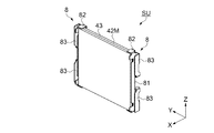
図2は、光学装置4の斜視図である。
光学装置4は、図1、図2に示すように、各色光用に設けられた電気光学装置40(第1色光用の電気光学装置を40B、第2色光用の電気光学装置を40G、第3色光用の電気光学装置を40R、とする)、および色合成光学装置としてのクロスダイクロイックプリズム400を備える。
FIG. 2 is a perspective view of the
As shown in FIGS. 1 and 2, the
図3は、電気光学装置40B,40Gを光の入射側から見た分解斜視図である。図4は、電気光学装置40B,40Gを光の射出側から見た分解斜視図である。なお、図3、図4は後述する入射側偏光板41を省略した図である。
電気光学装置40B,40Gそれぞれは、図3、図4に示すように、入射側偏光板41(図1参照)、光変調装置5、射出側偏光板42M、透明基板43、支持部7、挟持部8、および固定部材としての接着材(図示省略)を備えている。
電気光学装置40Rは、電気光学装置40B,40Gそれぞれの構成と比べ、透明基板43および挟持部8を備えず、射出側偏光板42Mとは異なる射出側偏光板42Yを備えている。電気光学装置40Bの光変調装置5を第1光変調装置5B、電気光学装置40Gの光変調装置5を第2光変調装置5G、電気光学装置40Rの光変調装置5を第3光変調装置5Rとする。
FIG. 3 is an exploded perspective view of the electro-
As shown in FIGS. 3 and 4, each of the electro-
The electro-
各色光用の入射側偏光板41は、有機偏光板であり、色分離光学系33で分離された各色光のうち、偏光変換素子323で揃えられた偏光光を透過し、その偏光光と異なる偏光光を吸収して各色光用の光変調装置5に射出する。入射側偏光板41は、ガラス板(図示省略)に貼り付けられ、光学部品用筐体38に支持される。
The incident-
各色光用の光変調装置5は、各色光用の入射側偏光板41から射出された各色光を画像情報に応じて変調する。具体的に、第1光変調装置5Bは、B光用の入射側偏光板41から射出されたB光を変調し、第2光変調装置5Gは、G光用の入射側偏光板41から射出されたG光を変調する。そして、第3光変調装置5Rは、R光用の入射側偏光板41から射出されたR光を変調する。光変調装置5については、後で詳細に説明する。
The
B光用の射出側偏光板42Mは、第1光変調装置5Bの光射出側に配置され、G光用の射出側偏光板42Mは、第2光変調装置5Gの光射出側に配置される。射出側偏光板42Mは、石英ガラス板等を基材とする無機偏光板であり、平面視矩形状に形成されている。具体的に、射出側偏光板42Mは、この基材の一方の面にアルミニウム等からなる微細な線状リブが平行に多数配列されたワイヤーグリッド層(図示省略)を有している。そして、射出側偏光板42Mは、線状リブの延出方向に対して垂直な偏光方向の偏光光(光変調装置5から射出された色光のうち一定方向の偏光光)を透過し、線状リブの延出方向に平行な偏光方向の偏光光を反射する。射出側偏光板42Mは、ワイヤーグリッド層側が光変調装置5側となるように配置される。
The emission
R光用の射出側偏光板42Yは、B光用、G光用に比べ発熱量が小さいため、有機偏光板が用いられている。射出側偏光板42Yは、入射側偏光板41と略同様の機能を有し、第3光変調装置5Rから射出されたR光のうち一定方向の偏光光を透過し、その偏光光と異なる偏光光を吸収してクロスダイクロイックプリズム400に射出する。射出側偏光板42Yは、図示は省略するがガラス板に貼り付けられ、粘着材を介して支持部7に固定される。
なお、R光用の射出側偏光板として無機偏光板を用い、電気光学装置40Rが電気光学装置40Bと同様に構成される態様であってもよい。また、各色光用の入射側偏光板41において、全て、あるいはいずれかが無機偏光板で構成される態様であってもよい。
The emission
In addition, an inorganic polarizing plate may be used as the emission side polarizing plate for the R light, and the electro-
透明基板43は、平面サイズが射出側偏光板42Mの平面サイズと略同じ平面サイズの矩形状に形成され、射出側偏光板42Mの光射出側、すなわち、射出側偏光板42Mのワイヤーグリッド層とは反対側に積層される。また、透明基板43は、光を透過する板材、例えば、射出側偏光板42Mの熱伝導率より高い熱伝導率のサファイア基板等が用いられている。後で詳細に説明するが、透明基板43は、射出側偏光板42Mに当接して配置され、射出側偏光板42Mの熱を放熱する。
The
支持部7は、各色光の光変調装置5を支持し、クロスダイクロイックプリズム400に取り付けられる。各色光用の支持部7は、共通の形状を有している。
挟持部8は、前述したように、電気光学装置40B,40Gそれぞれに設けられ、支持部7に係合されることで、支持部7とで射出側偏光板42Mと透明基板43とを挟持する。また、支持部7、挟持部8、射出側偏光板42Mおよび透明基板43は、射出側偏光板42Mと透明基板43とが支持部7と挟持部8とに挟持されることによって、偏光板ユニットPUとして構成される。支持部7および挟持部8については、後で詳細に説明する。
The
As described above, the sandwiching
クロスダイクロイックプリズム400は、4つの直角プリズムを貼り合わせた平面視略正方形状をなし、直角プリズム同士を貼り合わせた界面には、2つの誘電体多層膜が形成されている。クロスダイクロイックプリズム400は、3つの光入射側端面、および1つの光射出側端面を有している。電気光学装置40B,40G,40Rは、それぞれが3つの光入射側端面個別に対向して配置される。
The cross
また、プロジェクター1が机上等に据え置かれた姿勢において、電気光学装置40R,40G,40Bは、上方から見て、この順で、クロスダイクロイックプリズム400を中心に反時計回りに配置される(図1参照)。そして、クロスダイクロイックプリズム400は、電気光学装置を40B,40Rから射出されたB光およびR光を反射し、電気光学装置を40Gから射出されたG光を透過して、3色の変調された光を合成する。
Further, when the
投写レンズ36は、複数のレンズ(図示省略)を有し、クロスダイクロイックプリズム400にて合成され、クロスダイクロイックプリズム400の射出側端面から射出された光をスクリーン等の投写面SC上に拡大投写する。
The
冷却装置は、詳細な説明は省略するが、外装筐体の吸気口から外気を取り込む吸気ファン、取り込んだ外気を光学装置4等に導くダクト部材、内部の温まった空気を外装筐体の排気口から排出する排気ファン等を備えている。
Although a detailed description is omitted, the cooling device includes an intake fan that takes in outside air from an intake port of the exterior housing, a duct member that guides the taken-in outside air to the
〔光変調装置の構成〕
ここで、光変調装置5について詳細に説明する。
光変調装置5は、図3、図4に示すように、液晶パネル51、フレキシブル基板52、および保持部6を備えている。
[Configuration of optical modulator]
Here, the
As shown in FIGS. 3 and 4, the
液晶パネル51は、一対の透明基板に液晶が密閉封入されて形成され、図示しない微小画素がマトリックス状に形成された矩形状の画素領域を有している。また、液晶パネル51は、一対の透明基板の表面にそれぞれ配置された防塵ガラスを有している。
フレキシブル基板52は、一端が液晶パネル51に接続され、他端が制御部に接続されている。液晶パネル51は、フレキシブル基板52を介して制御部から入力された駆動信号に応じて液晶の配向状態が制御され、画素領域内に表示画像を形成する。
The
The
なお、以下では、説明の便宜上、1つの光変調装置5に注目して以下のように方向を定義する。液晶パネル51の法線方向(液晶パネルの画素に直交する方向)をX方向とし、X方向に直交し、液晶パネル51からフレキシブル基板52に向かう方向を+Z方向、X方向およびZ方向に直交する方向をY方向(左右方向)とする。そして、X方向における光変調装置5の射出側偏光板42M側を+X側、+Z側を上側とし光入射側から見た(図3の参照)光変調装置5の右側を+Y側とする。Z方向は、プロジェクター1が机上等に据え置かれた姿勢における上下方向となり、+Z側が上側となる。Z方向は第1方向に相当し、Y方向は第2方向に相当する。また、第1方向は、矩形状の射出側偏光板42Mの一辺に沿う方向である。
In the following, for convenience of description, attention is paid to one
保持部6は、図3に示すように、パネル枠61および固定板62を備え、液晶パネル51を保持する。
パネル枠61は、金属製で平面視矩形状に形成され、+X側に凹部が設けられ、この凹部に液晶パネル51が配置される。そして、凹部の底面には、入射側偏光板41(図1参照)を透過した光が入射する開口部611(図3参照)が形成されている。
固定板62は、金属製で平面視矩形状に形成され、液晶パネル51が収納されたパネル枠61の+X側に配置される。固定板62は、平面サイズがパネル枠61の平面サイズより大きく形成されており、液晶パネル51が配置されたパネル枠61は、固定板62にネジ固定される。固定板62は、中央に液晶パネル51を通過した光が通過する開口部621(図4参照)が形成され、四隅には、貫通孔622が設けられている。また、固定板62の左右両側の端部には、上下方向における略中央に、切欠き623が形成されている。
As shown in FIG. 3, the holding
The
The fixing
〔支持部および挟持部の構成〕
先ず、支持部7について詳細に説明する。
支持部7は、前述したように、電気光学装置40B,40G,40Rそれぞれに設けられ、共通の形状を有している。
支持部7は、板金からプレス加工により形成され、図3、図4に示すように、ベース部71、第1支持部72、および突出部73を有している。
ベース部71は、クロスダイクロイックプリズム400の光入射側端面に取り付けられる部位であり、平面視矩形に形成されている。ベース部71の中央には、射出側偏光板42Mから射出された光が通過する光通過用開口部711が形成されている。光通過用開口部711の左右両側の縁部には、Z方向がY方向より長い矩形状の張出部712が設けられている。張出部712は、ベース部71より−X側に位置しており、−X側の面には、両面テープ等の粘着材Taが配置されている。粘着材Taおよび張出部712は、透明基板43を受ける受部7Uとして機能する。
[Structure of support section and clamping section]
First, the
As described above, the
The supporting
The
第1支持部72は、ベース部71から延出し、光変調装置5を遊嵌支持する。すなわち、光変調装置5は、支持部7に対して位置調整が可能に支持される。
第1支持部72は、図4に示すように、ベース部71の四隅から光変調装置5側に略90°屈曲されて形成されており、先端部が保持部6の貫通孔622に遊びがある状態、すなわち上下左右にガタツキがある状態で挿通される大きさに形成されている。より具体的に、第1支持部72は、ベース部71上側の左右の隅部から突出する一対の第1支持部72u、およびベース部71下側の左右の隅部から突出する一対の第1支持部72dを有している。
The
As shown in FIG. 4, the
突出部73は、図3、図4に示すように、ベース部71の左右両側から屈曲され、光変調装置5側に突出している。左右の突出部73は、それぞれが第1支持部72uと第1支持部72dとの間に設けられている。そして、突出部73は、ベース部71側に形成された幅広部731、および上下方向の寸法が幅広部731より小さく、幅広部731に対して上下に段差を有する延出部732を有している。
As shown in FIGS. 3 and 4, the protruding
延出部732は、光変調装置5の切欠き623に挿通されるように延出している。また、左右の延出部732の先端部には、上下方向における中央に、互いに離間する方向に屈曲された凸部733が形成されている。
また、突出部73には、ベース部71寄りに、上下方向に併設された平面視矩形状の挿通孔73Hが2つ形成されている。
The extending
Further, in the protruding
次に、挟持部8について詳細に説明する。
挟持部8は、前述したように、電気光学装置40B,40Gそれぞれに設けられている。
挟持部8は、図3、図4に示すように、Y方向(第2方向、左右方向)において、射出側偏光板42Mおよび透明基板43の両側に一対配置され、支持部7とで、射出側偏光板42Mと透明基板43とを挟持する。挟持部8は、上下対称の形状を有し、左右の挟持部8は共通の形状を有している。
Next, the holding
The holding
As shown in FIGS. 3 and 4, the sandwiching
図5は、左右の挟持部8を示す斜視図である。図6は、左右の挟持部8が射出側偏光板42Mおよび透明基板43に配置された状態(この状態の左右の挟持部8、射出側偏光板42Mおよび透明基板43を「サブユニットSU」という)を光入射側から見た斜視図である。図7は、サブユニットSUを光射出側から見た斜視図である。
挟持部8は、板金からプレス加工により形成され、図5に示すように、第1板状部81、第2板状部82、第3板状部83、接続部84、屈曲部85、および付勢部86を有している。
第1板状部81は、図6、図7に示すように、射出側偏光板42Mおよび透明基板43の左右方向(Y方向)における一方の端面に沿うように、Z方向の長さがX方向の長さより長い長尺状に形成されている。
FIG. 5 is a perspective view showing the left and right holding
The sandwiching
As shown in FIGS. 6 and 7, the first plate-shaped
第2板状部82、第3板状部83、接続部84、屈曲部85、および付勢部86は、第1板状部81に対し、上側および下側にそれぞれ一対設けられている。
具体的に、第2板状部82は、第1板状部81の長手方向(Z方向)における両端からそれぞれ屈曲され、図6、図7に示すように、射出側偏光板42Mおよび透明基板43の上下方向における両端面にそれぞれ対向する平面を有し、この両端面に当接可能に形成されている。すなわち、第2板状部82は、上下方向(Z方向)における射出側偏光板42Mおよび透明基板43の移動を規制する。
The second plate-shaped
Specifically, the second plate-shaped
第3板状部83は、接続部84を介して、第1板状部81に繋がっている。
接続部84は、上下方向における第1板状部81の端部近傍に設けられ、第1板状部81の−X側の端部から屈曲されている。第3板状部83は、接続部84の端部から+X側に屈曲され、第1板状部81と所定の間隔で対向して配設されている。所定の間隔とは、支持部7における一方の突出部73(図3参照)が挿入可能な間隔である。一対の第3板状部83は、互いに近づく方向に延出し、接続部84側が固定端となる板バネ状に形成されている。
The third plate-shaped
The
屈曲部85は、第3板状部83の先端部に設けられ、第1板状部81側に屈曲されており、係合部に相当する。屈曲部85は、第1板状部81と第3板状部83との間に幅広部731が挿入されると、挿通孔73Hに挿入され、この挿通孔73Hの周縁と係合するように形成されている。
The
付勢部86は、第2板状部82の−X側の端部から屈曲され、この端部側が固定端となるバネ状に形成されている。一対の付勢部86は、Z方向(第1方向)において、互いに近づく方向に延出しており、図6に示すように、先端側が射出側偏光板42Mに当接するように屈曲されている。そして、左右の挟持部8における4つの付勢部86は、射出側偏光板42Mの四隅近傍に当接するように形成されている。
The biasing
ここで、偏光板ユニットPUの組立方法について、図8〜図10を用いて説明する。図8は、サブユニットSUおよび支持部7の斜視図である。図9は、偏光板ユニットPUの斜視図である。図10は、偏光板ユニットPUの断面図である。
先ず、図示しない治具上の所定の位置に一対の挟持部8を配置し、射出側偏光板42M、透明基板43をこの順で重ねサブユニットSUの状態にする(図8参照)。なお、図8は、各構成要素を視認しやすくするために、前述した治具を省略し、偏光板ユニットPUを起立させて示した図である。
Here, a method of assembling the polarizing plate unit PU will be described with reference to FIGS. FIG. 8 is a perspective view of the subunit SU and the
First, a pair of sandwiching
次に、図8に示すように、サブユニットSUの第1板状部81と第3板状部83との間、および挟持部8における上下の接続部84の間に、支持部7の延出部732を挿入する。
第3板状部83は、屈曲部85が第1板状部81側に屈曲されているので、前述したように、延出部732が挿入されると、屈曲部85が延出部732に押圧されて第1板状部81から離間する方向に撓む(図示省略)。
Next, as shown in FIG. 8, the
Since the
さらに、延出部732を挿入すると、幅広部731が第1板状部81と第3板状部83との間に挿入される。そして、第3板状部83がバネ性を有しているので、所定の位置で屈曲部85が挿通孔73Hに挿入され、挟持部8は、支持部7に係合される。そして、図9、図10に示すように、射出側偏光板42Mと透明基板43とは、付勢部86と受部7Uとで挟持され、偏光板ユニットPUが組み立てられる。
Further, when the extending
射出側偏光板42Mおよび透明基板43は、図10に示すように、透明基板43と張出部712との間に粘着材Taが介在するので、振動や衝撃に対する耐性が高く配置される。また、偏光板ユニットPUは、左右方向において、射出側偏光板42Mおよび透明基板43から板状の部位(第1板状部81、突出部73、および第3板状部83)が飛び出すこととなる。すなわち、偏光板ユニットPUは、左右方向において、射出側偏光板42Mおよび透明基板43からの飛び出し量が小さく構成されている。
As shown in FIG. 10, since the adhesive material Ta is interposed between the
このように、射出側偏光板42Mおよび透明基板43に対し、受部7Uは、ベース部71側に設けられ、付勢部86は、ベース部71とは反対側に設けられている。そして、屈曲部85が支持部7に係合されることで、付勢部86が射出側偏光板42Mを透明基板43側に付勢し、受部7Uが付勢部86により押圧される透明基板43を受ける。また、射出側偏光板42Mは、四隅近傍が付勢される。
Thus, with respect to the emission
第1光変調装置5Bは、偏光板ユニットPUにおける支持部7の第1支持部72に遊嵌支持される(この状態の第1光変調装置5Bおよび偏光板ユニットPUを「調整ユニット」という)。そして、調整ユニットは、第1光変調装置5Bを把持する第1治具、および凸部733に係合可能な第2治具(いずれも図示省略)を用いて、位置が調整される。
The first
具体的に、調整ユニットは、第1光変調装置5Bが第1治具に把持され、凸部733が第2治具に係合された状態で、クロスダイクロイックプリズム400に対して仮の位置に配置される。
そして、第1光変調装置5Bは、第1治具が移動されることによって位置が調整された後、固定部材としての接着材を用いて第1支持部72に固定される。そして、第1光変調装置5Bが固定されたユニットは、第1治具が解放された後、第2治具を用いてクロスダイクロイックプリズム400に対する位置が調整され、クロスダイクロイックプリズム400に接着固定される。
Specifically, the adjustment unit is placed at a temporary position with respect to the cross
Then, the position of the first
第2光変調装置5Gが遊嵌支持された調整ユニットは、第1光変調装置5Bが遊嵌支持された調整ユニットと同様に位置が調整される。
第3光変調装置5Rは、射出側偏光板42Yが固定された支持部7に遊嵌支持され、上述した方法と同様の方法で位置が調整される。
The position of the adjustment unit in which the second
The third
このように、光学装置4は、各色光用の光変調装置5の位置が調整されて組み立てられる。また、光学装置4は、図示しない冷却装置から送風された空気が下方から上方に流れて冷却される。射出側偏光板42M、およびこの射出側偏光板42Mに当接して放熱する透明基板43においても、冷却装置から送風された空気によって冷却される。
In this way, the
以上説明したように、本実施形態のプロジェクター1によれば、以下の効果を得ることができる。
(1)無機偏光板で形成された射出側偏光板42Mと透明基板43とは、挟持部8が支持部7に係合されることにより、付勢部86と受部7Uとに挟持される。すなわち、第1光変調装置5B、第2光変調装置5Gをそれぞれ支持する支持部7を利用して射出側偏光板42Mと透明基板43とを当接させた状態を維持することができる。よって、接着材を用いることなく、また、部品点数の増加を抑制して、射出側偏光板42Mと透明基板43とを当接させる構成が可能となる。よって、製造が容易で、高輝度の色光が入射することによって発熱する射出側偏光板42Mの熱を効率よく放熱できる光学装置4の提供が可能となる。
射出側偏光板42Mで発生した熱は、射出側偏光板42Mに当接する透明基板43に移動され、透明基板43から挟持部8の第1板状部81、第2板状部82または付勢部86に伝導される。挟持部8に伝導された熱は、第1板状部81、第3板状部83、接続部84または屈曲部85を介して、支持部7(突出部73)に伝導されるので、高輝度の色光が入射することによって発熱する射出側偏光板42Mの熱を効率よく放熱できる。
As described above, according to the
(1) The exit-side
The heat generated in the emission
(2)偏光板ユニットPUにおいて、挟持部8は、Z方向において一対の付勢部86を有し、Y方向において射出側偏光板42Mおよび透明基板43の両側に一対設けられている。そして、射出側偏光板42Mと透明基板43とは、射出側偏光板42Mの四隅の近傍で挟持されている。これによって、射出側偏光板42Mと透明基板43とを広い領域で当接させることが可能となるので、射出側偏光板42Mのより効率的な放熱が可能となる。
(2) In the polarizing plate unit PU, the sandwiching
(3)射出側偏光板42Mおよび透明基板43は、一対の挟持部8の第1板状部81によってY方向の両側が支持され、各挟持部8の第2板状部82によってZ方向の両側が支持される。また、挟持部8は、板金で形成され、第1板状部81、第2板状部82、第3板状部83、および付勢部86が一体で形成されている。よって、簡単な部品構成で平面方向(Y方向およびZ方向)における射出側偏光板42Mおよび透明基板43を支持し、射出側偏光板42Mを透明基板43側に付勢する構成が可能となる。
(3) Both sides of the emission
(4)射出側偏光板42Mおよび透明基板43の両側に挟持部8を配置し、第1板状部81と第3板状部83との間に突出部73を挿入するという簡単な作業で、偏光板ユニットPUを組み立てることができる。よって、偏光板ユニットPUの製造の簡素化が可能となる。
(4) With a simple operation of disposing the sandwiching
(5)偏光板ユニットPUは、Y方向において、支持部7および挟持部8の射出側偏光板42Mおよび透明基板43から板状の部位が飛び出るという、飛び出し量が小さく構成されるので、Y方向における小型化が可能となる。よって、電気光学装置40B,40GそれぞれのY方向における小型化が可能となる。また、電気光学装置40Rは、挟持部8を備えず、共通の支持部7を備えているので、Y方向における小型化が可能となる。よって、光学装置4の小型化、あるいは、隣り合う電気光学装置40間に部材を配置することや、冷却のためのスペースを設けることが可能となる。
(5) Since the polarizing plate unit PU is configured to have a small protrusion amount in the Y direction, that is, a plate-shaped portion protrudes from the emission
(6)光学装置4は、各色光用の光変調装置5の位置が調整可能に構成されているので、画素ずれを抑制した光を射出することができる。
(6) Since the
(7)射出側偏光板42Mは、ワイヤーグリッド層を有し、ワイヤーグリッド層側が光変調装置5側となるように配置されている。そして透明基板43は、射出側偏光板42Mのワイヤーグリッド層とは反対側に積層されている。すなわち、光変調装置5から射出された光が、直接、ワイヤーグリッド層に入射するように構成されている。これによって、光変調装置5とワイヤーグリッド層との間に部材が配置される構成(ワイヤーグリッド層とは反対側から光が入射する構成や、透明基板43、射出側偏光板42Mの順で光が通過する構成)に比べ、光変調装置5から射出された光のワイヤーグリッド層に至るまでの屈折等を低減することができる。よって、光学装置4は、色むら等を抑制した光を射出することが可能となる。
(7) The exit-
(8)プロジェクター1は、上述した光学装置4を備えているので、明るく高画質な画像を投写できると共に、小型化が可能となる。
(8) Since the
なお、本発明は上述した実施形態に限定されず、上述した実施形態に種々の変更や改良などを加えることが可能である。変形例を以下に述べる。
(変形例1)
射出側偏光板42Mの光射出側に光学素子(例えば、光の位相差を補償する補償素子や、位相差板等)を備える偏光板ユニットを構成してもよい。
図11は、変形例における偏光板ユニットPUxの断面図である。
偏光板ユニットPUxは、図11に示すように、前記実施形態の支持部7とは異なる支持部17を備え、さらに透明基板43の光射出側に配置される光学素子としての位相差板44を備えている。
The present invention is not limited to the above-described embodiment, and various changes and improvements can be added to the above-described embodiment. A modified example will be described below.
(Modification 1)
A polarizing plate unit including an optical element (for example, a compensating element for compensating the phase difference of light, a retardation plate, or the like) on the light emitting side of the emitting
FIG. 11 is a cross-sectional view of the polarizing plate unit PUx in the modified example.
As shown in FIG. 11, the polarization unit PUx includes a
支持部17は、本体部材171および補助部材172を備える。本体部材171は、前記実施形態の支持部7に類似する形状を有し、図11に示すように、支持部7における張出部712よりベース部171b寄りに形成された張出部1712を有している。
The
補助部材172は、板金で形成され、図11に示すように、透明基板43と位相差板44との間に配置される。補助部材172は、粘着材(図示省略)を介して位相差板44の光入射側の面の縁部に当接する第1平坦部172a、第1平坦部172aより透明基板43側に突出し、粘着材(図示省略)を介して透明基板43を受ける第2平坦部172bを有している。第2平坦部172bには、射出側偏光板42Mおよび透明基板43を透過した光が通過する開口部が設けられている。
The
偏光板ユニットPUxは、サブユニットSUに位相差板44が粘着された補助部材172が載置され、前記実施形態と同様に、本体部材171が挟持部8に挿入されることで組み立てられる。そして、射出側偏光板42Mと透明基板43とは、付勢部86と第2平坦部172bとに挟持される。補助部材172は、位相差板44を支持する第2支持部に相当し、粘着材が配置された第2平坦部172bは、受部に相当する。
この変形例の構成によれば、射出側偏光板42Mと透明基板43とを挟持させる構成を維持しつつ、コントラスト比や視野角特性等の良好な光を射出する光学装置4の提供が可能となる。
また、射出側偏光板42Mで発生した熱は、射出側偏光板42Mに当接する透明基板43に移動され、透明基板43から挟持部8の第1板状部81、第2板状部82または付勢部86に伝導される。挟持部8に伝導された熱は、第1板状部81、第3板状部83、接続部84または屈曲部85を介して、支持部17に伝導されるので、高輝度の色光が入射することによって発熱する射出側偏光板42Mの熱を効率よく放熱できる。
The polarizing plate unit PUx is assembled by mounting the
According to the configuration of this modified example, it is possible to provide the
Further, the heat generated by the emission
(変形例2)
前記実施形態では、第1色光をB光としたが、B光以外の色光、例えば、G光を第1色光として構成してもよい。
(Modification 2)
In the above-described embodiment, the first color light is the B light, but the color light other than the B light, for example, the G light may be configured as the first color light.
(変形例3)
前記実施形態では、挟持部8が射出側偏光板42Mを付勢し、支持部7が透明基板43を受けるように構成されているが、挟持部8が透明基板43を付勢し、支持部7が射出側偏光板を受けるように構成してもよい。
(Modification 3)
In the above-described embodiment, the sandwiching
(変形例4)
前記実施形態の受部7Uは、粘着材Taを備えているが、粘着材Taを備えない張出部712を受部として構成してもよい。
(Modification 4)
Although the receiving
(変形例5)
前記実施形態の光学装置4は、R光、G光、およびB光に対応する3つの光変調装置5を備えた、いわゆる3板方式を採用しているが、これに限らず、2つまたは4つ以上の光変調装置を備えた光学装置にも適用できる。
また、前記実施形態では、透過型の液晶パネル51を有する光変調装置5を支持部7が支持するように構成されているが、反射型の液晶パネルを有する光変調装置を支持部が支持する構成にも適用可能である。
(Modification 5)
The
Further, in the above-described embodiment, the supporting
(変形例6)
前記実施形態の光源装置31は、放電型の光源311を採用しているが、その他の方式の光源や発光ダイオード、レーザーダイオード等の固体光源で構成してもよい。
(Modification 6)
Although the
1…プロジェクター、4…光学装置、5…光変調装置、5B…第1光変調装置、5G…第2光変調装置、5R…第3光変調装置、6…保持部、7,17…支持部、8…挟持部、36…投写レンズ(投写光学装置)、42M…射出側偏光板(無機偏光板)、43…透明基板、44…位相差板(光学素子)、51…液晶パネル、71,171b…ベース部、72…第1支持部、73…突出部、73H…挿通孔、81…第1板状部、82…第2板状部、83…第3板状部、85…屈曲部(係合部)、86…付勢部、172…補助部材(第2支持部)、172b…第2平坦部(受部)、311…光源、400…クロスダイクロイックプリズム(色合成光学装置)、712…張出部(受部)。
DESCRIPTION OF
Claims (9)
前記第1光変調装置の光射出側に配置された無機偏光板と、
前記無機偏光板に積層され、光を透過する透明基板と、
前記第1光変調装置を支持し、前記色合成光学装置に取り付けられる支持部と、
前記支持部とで前記無機偏光板と前記透明基板とを挟持する挟持部と、
を備え、
前記挟持部は、
前記支持部に係合する係合部と、
前記係合部が前記支持部に係合されることで、前記無機偏光板および前記透明基板のいずれか一方を他方側に付勢する付勢部と、
を有し、
前記支持部は、前記付勢部により押圧される前記他方を受ける受部を有し、
前記無機偏光板は、平面視矩形状に形成され、
前記無機偏光板の一辺に沿う方向を第1方向とし、前記第1方向に交差するとともに前記無機偏光板の表面に沿う方向を第2方向として、
前記挟持部は、
前記無機偏光板および前記透明基板の一方の前記第2方向における端面に沿う第1板状部を有し、
前記挟持部は、
前記第1板状部の前記第1方向における両端からそれぞれ屈曲され、前記第1方向において、前記無機偏光板および前記透明基板の移動を規制する一対の第2板状部を有することを特徴とする光学装置。 A first light modulator for modulating the first color light, a second light modulator for modulating the second color light, and a color combiner for combining the color lights respectively modulated by the first light modulator and the second light modulator. An optical device including:
An inorganic polarizing plate arranged on the light exit side of the first light modulator;
A transparent substrate laminated on the inorganic polarizing plate and transmitting light,
A support unit that supports the first light modulator and is attached to the color combining optical device;
A sandwiching unit that sandwiches the inorganic polarizing plate and the transparent substrate with the supporting unit,
Equipped with
The sandwiching portion is
An engagement portion that engages with the support portion,
By the engagement portion is engaged with the support portion, a biasing portion that biases one of the inorganic polarizing plate and the transparent substrate to the other side,
Have
The supporting portion has a receiving portion that receives the other of the urging portions that is pressed by the urging portion,
The inorganic polarizing plate is formed in a rectangular shape in plan view,
A direction along one side of the inorganic polarizing plate is a first direction, and a direction intersecting the first direction and along a surface of the inorganic polarizing plate is a second direction,
The sandwiching portion is
A first plate-shaped portion along an end face in one of the second direction of the inorganic polarizing plate and the transparent substrate,
The sandwiching portion is
A pair of second plate-shaped portions that are bent from both ends of the first plate-shaped portion in the first direction and restrict movement of the inorganic polarizing plate and the transparent substrate in the first direction. Optical device.
前記付勢部は、前記無機偏光板および前記透明基板のいずれか一方に接することを特徴とする光学装置。 The optical device according to claim 1, wherein
The optical device, wherein the urging portion is in contact with either one of the inorganic polarizing plate and the transparent substrate.
前記付勢部は、前記第1方向において、互いに近づくように延出する一対の付勢部を有し、
前記一対の前記付勢部は、前記一対の第2板状部からそれぞれ屈曲していることを特徴とする光学装置。 The optical device according to claim 1 , wherein
The urging portion has a pair of urging portions extending so as to approach each other in the first direction,
The optical device, wherein the pair of urging portions are respectively bent from the pair of second plate-shaped portions.
前記挟持部は、
前記第1板状部と所定の間隔で対向して配設されるとともに前記第1板状部に接続された第3板状部を有し、
前記係合部は、前記第3板状部の先端部に設けられ、前記第1板状部側に屈曲された屈
曲部を有し、
前記支持部は、
前記色合成光学装置に取り付けられるベース部と、
前記ベース部から突出し、前記第1板状部と前記第3板状部との間に挿入される突出部と、
を有し、
前記突出部には、前記屈曲部が係合する挿通孔が形成され、
前記受部は、前記無機偏光板および前記透明基板に対し、前記ベース部側に設けられ、
前記付勢部は、前記無機偏光板および前記透明基板に対し、前記ベース部とは反対側に設けられていることを特徴とする光学装置。 The optical device according to claim 1 , wherein
The sandwiching portion is
A third plate-shaped portion that is arranged to face the first plate-shaped portion at a predetermined interval and is connected to the first plate-shaped portion,
The engagement portion is provided at a tip end portion of the third plate-shaped portion, and has a bent portion that is bent toward the first plate-shaped portion,
The support portion is
A base portion attached to the color combining optical device;
A projecting portion projecting from the base portion and inserted between the first plate-shaped portion and the third plate-shaped portion;
Have
An insertion hole for engaging the bent portion is formed in the protrusion,
The receiving portion is provided on the base portion side with respect to the inorganic polarizing plate and the transparent substrate,
The optical device, wherein the biasing portion is provided on the side opposite to the base portion with respect to the inorganic polarizing plate and the transparent substrate.
前記第1光変調装置の光射出側に配置された無機偏光板と、
前記無機偏光板に積層され、光を透過する透明基板と、
前記第1光変調装置を支持し、前記色合成光学装置に取り付けられる支持部と、
前記支持部とで前記無機偏光板と前記透明基板とを挟持する挟持部と、
を備え、
前記挟持部は、
前記支持部に係合する係合部と、
前記係合部が前記支持部に係合されることで、前記無機偏光板および前記透明基板のいずれか一方を他方側に付勢する付勢部と、
を有し、
前記支持部は、前記付勢部により押圧される前記他方を受ける受部を有し、
前記支持部は、前記第1光変調装置を遊嵌支持する第1支持部を有し、
前記第1光変調装置および前記第1支持部は、固定部材によって固定されることを特徴とする光学装置。 A first light modulator for modulating the first color light, a second light modulator for modulating the second color light, and a color combiner for combining the color lights respectively modulated by the first light modulator and the second light modulator. An optical device including:
An inorganic polarizing plate arranged on the light exit side of the first light modulator;
A transparent substrate laminated on the inorganic polarizing plate and transmitting light,
A support unit that supports the first light modulator and is attached to the color combining optical device;
A sandwiching unit that sandwiches the inorganic polarizing plate and the transparent substrate with the supporting unit,
Equipped with
The sandwiching portion is
An engagement portion that engages with the support portion,
By the engagement portion is engaged with the support portion, a biasing portion that biases one of the inorganic polarizing plate and the transparent substrate to the other side,
Have
The supporting portion has a receiving portion that receives the other of the urging portions that is pressed by the urging portion,
The support portion has a first support portion that loosely fits and supports the first light modulator,
The optical device, wherein the first light modulator and the first support are fixed by a fixing member.
前記無機偏光板は、基材と前記基材の一方の面に形成されたワイヤーグリッド層とを有し、前記ワイヤーグリッド層と前記第1光変調装置とが対向するように配置され、
前記透明基板は、前記無機偏光板の前記ワイヤーグリッド層とは反対側に当接されることを特徴とする光学装置。 The optical device according to any one of claims 1 to 5 , wherein:
The inorganic polarizing plate has a base material and a wire grid layer formed on one surface of the base material, and the wire grid layer and the first light modulation device are arranged to face each other,
The optical device, wherein the transparent substrate is in contact with a side of the inorganic polarizing plate opposite to the wire grid layer.
前記第1光変調装置の光射出側に配置された無機偏光板と、
前記無機偏光板に積層され、光を透過する透明基板と、
前記第1光変調装置を支持し、前記色合成光学装置に取り付けられる支持部と、
前記支持部とで前記無機偏光板と前記透明基板とを挟持する挟持部と、
を備え、
前記挟持部は、
前記支持部に係合する係合部と、
前記係合部が前記支持部に係合されることで、前記無機偏光板および前記透明基板のいずれか一方を他方側に付勢する付勢部と、
を有し、
前記支持部は、前記付勢部により押圧される前記他方を受ける受部を有し、
前記無機偏光板の光射出側に配置された光学素子を備え、
前記支持部は、前記光学素子と前記無機偏光板との間に設けられる第2支持部を有し、
前記第2支持部は、前記受部を有していることを特徴とする光学装置。 A first light modulator for modulating the first color light, a second light modulator for modulating the second color light, and a color combiner for combining the color lights respectively modulated by the first light modulator and the second light modulator. An optical device including:
An inorganic polarizing plate arranged on the light exit side of the first light modulator;
A transparent substrate laminated on the inorganic polarizing plate and transmitting light,
A support unit that supports the first light modulator and is attached to the color combining optical device;
A sandwiching unit that sandwiches the inorganic polarizing plate and the transparent substrate with the supporting unit,
Equipped with
The sandwiching portion is
An engagement portion that engages with the support portion,
By the engagement portion is engaged with the support portion, a biasing portion that biases one of the inorganic polarizing plate and the transparent substrate to the other side,
Have
The supporting portion has a receiving portion that receives the other of the urging portions that is pressed by the urging portion,
An optical element arranged on the light exit side of the inorganic polarizing plate,
The supporting part has a second supporting part provided between the optical element and the inorganic polarizing plate,
The optical device, wherein the second support portion includes the receiving portion.
前記第1光変調装置の光射出側に配置された無機偏光板と、
前記無機偏光板に積層され、光を透過する透明基板と、
前記第1光変調装置を支持し、前記色合成光学装置に取り付けられる支持部と、
前記支持部とで前記無機偏光板と前記透明基板とを挟持する挟持部と、
を備え、
前記挟持部は、
前記支持部に係合する係合部と、
前記係合部が前記支持部に係合されることで、前記無機偏光板および前記透明基板のいずれか一方を他方側に付勢する付勢部と、
を有し、
前記支持部は、前記付勢部により押圧される前記他方を受ける受部を有し、
前記無機偏光板は、平面視矩形状に形成され、
前記無機偏光板の一辺に沿う方向を第1方向とし、前記第1方向に交差するとともに前記無機偏光板の表面に沿う方向を第2方向として、
前記挟持部は、前記一辺側と、前記一辺側から前記第2方向に離間する他辺側とに設けられる一対の挟持部を有していることを特徴とする光源装置。 A first light modulator for modulating the first color light, a second light modulator for modulating the second color light, and a color combiner for combining the color lights respectively modulated by the first light modulator and the second light modulator. An optical device including:
An inorganic polarizing plate arranged on the light exit side of the first light modulator;
A transparent substrate laminated on the inorganic polarizing plate and transmitting light,
A support unit that supports the first light modulator and is attached to the color combining optical device;
A sandwiching unit that sandwiches the inorganic polarizing plate and the transparent substrate with the supporting unit,
Equipped with
The sandwiching portion is
An engagement portion that engages with the support portion,
By the engagement portion is engaged with the support portion, a biasing portion that biases one of the inorganic polarizing plate and the transparent substrate to the other side,
Have
The supporting portion has a receiving portion that receives the other of the urging portions that is pressed by the urging portion,
The inorganic polarizing plate is formed in a rectangular shape in plan view,
A direction along one side of the inorganic polarizing plate is a first direction, and a direction intersecting the first direction and along a surface of the inorganic polarizing plate is a second direction,
The said clamping part has a pair of clamping parts provided in the said one side and the other side separated from the said one side in the said 2nd direction, The light source device characterized by the above-mentioned.
前記光源から射出された光が入射する請求項1〜請求項8いずれか一項に記載の光学装置と、
前記光学装置から射出された光を投写する投写光学装置と、
を備えることを特徴とするプロジェクター。 A light source,
An optical device according to claims 1 to 8 any one of the light emitted from the light source is incident,
A projection optical device for projecting light emitted from the optical device;
A projector comprising:
Priority Applications (3)
| Application Number | Priority Date | Filing Date | Title |
|---|---|---|---|
| JP2016139150A JP6733378B2 (en) | 2016-07-14 | 2016-07-14 | Optical device and projector |
| CN201710513072.XA CN107621747B (en) | 2016-07-14 | 2017-06-29 | Optical device and projector |
| US15/640,836 US10345690B2 (en) | 2016-07-14 | 2017-07-03 | Optical apparatus and projector |
Applications Claiming Priority (1)
| Application Number | Priority Date | Filing Date | Title |
|---|---|---|---|
| JP2016139150A JP6733378B2 (en) | 2016-07-14 | 2016-07-14 | Optical device and projector |
Publications (3)
| Publication Number | Publication Date |
|---|---|
| JP2018010181A JP2018010181A (en) | 2018-01-18 |
| JP2018010181A5 JP2018010181A5 (en) | 2019-07-11 |
| JP6733378B2 true JP6733378B2 (en) | 2020-07-29 |
Family
ID=60940546
Family Applications (1)
| Application Number | Title | Priority Date | Filing Date |
|---|---|---|---|
| JP2016139150A Active JP6733378B2 (en) | 2016-07-14 | 2016-07-14 | Optical device and projector |
Country Status (3)
| Country | Link |
|---|---|
| US (1) | US10345690B2 (en) |
| JP (1) | JP6733378B2 (en) |
| CN (1) | CN107621747B (en) |
Families Citing this family (6)
| Publication number | Priority date | Publication date | Assignee | Title |
|---|---|---|---|---|
| JP6914484B2 (en) * | 2018-03-14 | 2021-08-04 | オムロン株式会社 | Photoelectric sensor and sensor system |
| CN209590506U (en) * | 2019-01-31 | 2019-11-05 | 中强光电股份有限公司 | Optical facilities and projection arrangement |
| JP2020154197A (en) * | 2019-03-22 | 2020-09-24 | セイコーエプソン株式会社 | Optical module and control method of the same, and projection type display device |
| JP2020154196A (en) | 2019-03-22 | 2020-09-24 | セイコーエプソン株式会社 | Optical module and control method of the same, and projection type display device |
| JP2021033032A (en) | 2019-08-23 | 2021-03-01 | セイコーエプソン株式会社 | projector |
| JP7309774B2 (en) * | 2021-04-07 | 2023-07-18 | 矢崎総業株式会社 | vehicle display |
Family Cites Families (10)
| Publication number | Priority date | Publication date | Assignee | Title |
|---|---|---|---|---|
| CN100473519C (en) * | 2001-11-07 | 2009-04-01 | 富士胶片株式会社 | Polarizing plate, production method thereof and liquid crystal display using the same |
| US6961165B2 (en) * | 2002-12-24 | 2005-11-01 | Seiko Epson Corporation | Optical modulation device holding body, optical device, and projector |
| JP4657928B2 (en) * | 2006-01-05 | 2011-03-23 | 富士フイルム株式会社 | Polarizing element, cross dichroic prism, liquid crystal projector, and manufacturing method of polarizing element |
| CN101271263A (en) * | 2007-03-20 | 2008-09-24 | 精工爱普生株式会社 | Optical apparatus and projector |
| JP5150469B2 (en) | 2008-11-28 | 2013-02-20 | 株式会社日立製作所 | Optical unit and projection type liquid crystal display device using the same |
| JP2010181581A (en) * | 2009-02-05 | 2010-08-19 | Sumitomo Chemical Co Ltd | Polarizing plate |
| JP2010224401A (en) * | 2009-03-25 | 2010-10-07 | Seiko Epson Corp | Projector |
| JP5516168B2 (en) * | 2010-07-14 | 2014-06-11 | セイコーエプソン株式会社 | projector |
| JP5790206B2 (en) * | 2011-06-30 | 2015-10-07 | セイコーエプソン株式会社 | projector |
| JP2015194684A (en) * | 2014-03-26 | 2015-11-05 | セイコーエプソン株式会社 | Polarizing plate unit and projector |
-
2016
- 2016-07-14 JP JP2016139150A patent/JP6733378B2/en active Active
-
2017
- 2017-06-29 CN CN201710513072.XA patent/CN107621747B/en active Active
- 2017-07-03 US US15/640,836 patent/US10345690B2/en active Active
Also Published As
| Publication number | Publication date |
|---|---|
| CN107621747B (en) | 2021-06-11 |
| US10345690B2 (en) | 2019-07-09 |
| US20180017857A1 (en) | 2018-01-18 |
| JP2018010181A (en) | 2018-01-18 |
| CN107621747A (en) | 2018-01-23 |
Similar Documents
| Publication | Publication Date | Title |
|---|---|---|
| JP6733378B2 (en) | Optical device and projector | |
| JP4582213B2 (en) | Optical apparatus and projector | |
| US9420244B2 (en) | Reflective polarizing plate apparatus, electro-optic apparatus, optical apparatus, and projector | |
| JP2007292924A (en) | Optical device and projector equipped with optical device | |
| JP4033210B2 (en) | Optical apparatus and projector equipped with the same | |
| US9348199B2 (en) | Optical device, projector, and method of manufacturing optical device | |
| JPWO2004012007A1 (en) | Prism structure and projector | |
| KR100705876B1 (en) | Optical assembly and projector | |
| JP2015194684A (en) | Polarizing plate unit and projector | |
| US8827457B2 (en) | Projector | |
| JP4661635B2 (en) | Optical apparatus and projector | |
| JP2018017963A (en) | projector | |
| JP2007256499A (en) | Light modulating device, optical apparatus and projector | |
| JP5849589B2 (en) | Reflective polarizing plate device, electro-optical device, optical device, and projector | |
| JP2009210779A (en) | Optical device and projector | |
| JP5516168B2 (en) | projector | |
| JP2021033032A (en) | projector | |
| JP5776392B2 (en) | Reflective polarizing plate device, electro-optical device, optical device, and projector | |
| JP2011075770A (en) | Optical modulation device and projector | |
| JP6020673B2 (en) | Reflective polarizing plate device, electro-optical device, optical device, and projector | |
| JP5834711B2 (en) | Reflective polarizing plate device, electro-optical device, optical device, and projector | |
| JP2012208297A (en) | Liquid crystal device and electronic apparatus | |
| JP2009151170A (en) | Optical device and projector | |
| JP2006243643A (en) | Optical conversion element and projector | |
| JP2010049103A (en) | Projection type image display |
Legal Events
| Date | Code | Title | Description |
|---|---|---|---|
| RD05 | Notification of revocation of power of attorney |
Free format text: JAPANESE INTERMEDIATE CODE: A7425 Effective date: 20190322 |
|
| RD03 | Notification of appointment of power of attorney |
Free format text: JAPANESE INTERMEDIATE CODE: A7423 Effective date: 20190402 |
|
| A521 | Written amendment |
Free format text: JAPANESE INTERMEDIATE CODE: A523 Effective date: 20190603 |
|
| A621 | Written request for application examination |
Free format text: JAPANESE INTERMEDIATE CODE: A621 Effective date: 20190603 |
|
| A977 | Report on retrieval |
Free format text: JAPANESE INTERMEDIATE CODE: A971007 Effective date: 20200305 |
|
| A131 | Notification of reasons for refusal |
Free format text: JAPANESE INTERMEDIATE CODE: A131 Effective date: 20200310 |
|
| A521 | Written amendment |
Free format text: JAPANESE INTERMEDIATE CODE: A523 Effective date: 20200423 |
|
| TRDD | Decision of grant or rejection written | ||
| A01 | Written decision to grant a patent or to grant a registration (utility model) |
Free format text: JAPANESE INTERMEDIATE CODE: A01 Effective date: 20200609 |
|
| A61 | First payment of annual fees (during grant procedure) |
Free format text: JAPANESE INTERMEDIATE CODE: A61 Effective date: 20200622 |
|
| R150 | Certificate of patent or registration of utility model |
Ref document number: 6733378 Country of ref document: JP Free format text: JAPANESE INTERMEDIATE CODE: R150 |