JP5513070B2 - Disk drive - Google Patents
Disk drive Download PDFInfo
- Publication number
- JP5513070B2 JP5513070B2 JP2009243252A JP2009243252A JP5513070B2 JP 5513070 B2 JP5513070 B2 JP 5513070B2 JP 2009243252 A JP2009243252 A JP 2009243252A JP 2009243252 A JP2009243252 A JP 2009243252A JP 5513070 B2 JP5513070 B2 JP 5513070B2
- Authority
- JP
- Japan
- Prior art keywords
- laminated core
- disk drive
- drive device
- hub
- press
- Prior art date
- Legal status (The legal status is an assumption and is not a legal conclusion. Google has not performed a legal analysis and makes no representation as to the accuracy of the status listed.)
- Expired - Fee Related
Links
Images


Classifications
-
- G—PHYSICS
- G11—INFORMATION STORAGE
- G11B—INFORMATION STORAGE BASED ON RELATIVE MOVEMENT BETWEEN RECORD CARRIER AND TRANSDUCER
- G11B33/00—Constructional parts, details or accessories not provided for in the other groups of this subclass
- G11B33/02—Cabinets; Cases; Stands; Disposition of apparatus therein or thereon
- G11B33/08—Insulation or absorption of undesired vibrations or sounds
-
- G—PHYSICS
- G11—INFORMATION STORAGE
- G11B—INFORMATION STORAGE BASED ON RELATIVE MOVEMENT BETWEEN RECORD CARRIER AND TRANSDUCER
- G11B19/00—Driving, starting, stopping record carriers not specifically of filamentary or web form, or of supports therefor; Control thereof; Control of operating function ; Driving both disc and head
- G11B19/20—Driving; Starting; Stopping; Control thereof
- G11B19/2009—Turntables, hubs and motors for disk drives; Mounting of motors in the drive
- G11B19/2018—Incorporating means for passive damping of vibration, either in the turntable, motor or mounting
-
- G—PHYSICS
- G11—INFORMATION STORAGE
- G11B—INFORMATION STORAGE BASED ON RELATIVE MOVEMENT BETWEEN RECORD CARRIER AND TRANSDUCER
- G11B25/00—Apparatus characterised by the shape of record carrier employed but not specific to the method of recording or reproducing, e.g. dictating apparatus; Combinations of such apparatus
- G11B25/04—Apparatus characterised by the shape of record carrier employed but not specific to the method of recording or reproducing, e.g. dictating apparatus; Combinations of such apparatus using flat record carriers, e.g. disc, card
- G11B25/043—Apparatus characterised by the shape of record carrier employed but not specific to the method of recording or reproducing, e.g. dictating apparatus; Combinations of such apparatus using flat record carriers, e.g. disc, card using rotating discs
-
- H—ELECTRICITY
- H02—GENERATION; CONVERSION OR DISTRIBUTION OF ELECTRIC POWER
- H02K—DYNAMO-ELECTRIC MACHINES
- H02K1/00—Details of the magnetic circuit
- H02K1/06—Details of the magnetic circuit characterised by the shape, form or construction
- H02K1/12—Stationary parts of the magnetic circuit
- H02K1/18—Means for mounting or fastening magnetic stationary parts on to, or to, the stator structures
- H02K1/187—Means for mounting or fastening magnetic stationary parts on to, or to, the stator structures to inner stators
Description
本発明は、積層コアを有するディスク駆動装置に関する。 The present invention relates to a disk drive device having a laminated core.
コンピュータの記憶装置等に使用されるメディアとしては、ハードディスクドライブが知られている。ハードディスクドライブでは、記録トラックが形成された磁気記録ディスクをブラシレスモータにより高速で回転させる。記録トラックに含まれる磁気データのリード/ライトのために、磁気記録ディスクの表面に磁気ヘッドを僅かな隙間をもって配置する。 A hard disk drive is known as a medium used for a storage device of a computer. In a hard disk drive, a magnetic recording disk on which recording tracks are formed is rotated at a high speed by a brushless motor. In order to read / write magnetic data contained in the recording track, a magnetic head is disposed on the surface of the magnetic recording disk with a slight gap.
多くのブラシレスモータは、ステータの一部としてコイルを巻き付けるための積層コアを有する。この積層コアは電磁鋼板を複数枚積層して形成されることが知られている(特許文献1参照)。 Many brushless motors have a laminated core for winding a coil as part of the stator. It is known that this laminated core is formed by laminating a plurality of electromagnetic steel sheets (see Patent Document 1).
ハードディスクドライブの大容量化を進めるひとつの手法として、記録トラックの幅を狭くし、磁気ヘッドを磁気記録ディスクの表面に近づけることがある。磁気ヘッドと磁気記録ディスクの表面との間の隙間が狭いと、たとえば積層コア由来の回転軸方向の振動に応じて磁気ヘッドが回転軸方向に振動をすることで、この隙間が変動することがある。磁気ヘッドと磁気記録ディスクの表面との隙間が変動すると磁気ヘッドの出力信号の振幅も変動して、ハードディスクドライブのデータのリードライトのエラーレートを悪化させうる。また最悪の場合、磁気ヘッドが磁気記録ディスクに接触する可能性もある。これはハードディスクドライブに生じる不具合の原因となりうる。また、積層コア由来の回転軸方向の振動が伝達の過程で方向が変化して磁気ヘッドを面方向に振動させることがある。この場合、記録トラックの幅が狭いと記録トラックのトレースが乱れる可能性がある。 One technique for increasing the capacity of a hard disk drive is to reduce the width of the recording track and bring the magnetic head closer to the surface of the magnetic recording disk. If the gap between the magnetic head and the surface of the magnetic recording disk is narrow, for example, the gap fluctuates because the magnetic head vibrates in the direction of the rotation axis in response to vibration in the direction of the rotation axis derived from the laminated core. is there. When the gap between the magnetic head and the surface of the magnetic recording disk fluctuates, the amplitude of the output signal of the magnetic head also fluctuates, which can deteriorate the read / write error rate of the data in the hard disk drive. In the worst case, the magnetic head may come into contact with the magnetic recording disk. This can cause problems with the hard disk drive. Also, the direction of the rotation axis derived from the laminated core may change its direction in the course of transmission, causing the magnetic head to vibrate in the plane direction. In this case, if the width of the recording track is narrow, the recording track trace may be disturbed.
本発明はこうした状況に鑑みてなされたものであり、その目的は振動を低減させたディスク駆動装置の提供にある。 The present invention has been made in view of such circumstances, and an object thereof is to provide a disk drive device with reduced vibration.
本発明のある態様は、ディスク駆動装置に関する。このディスク駆動装置は、記録ディスクが載置されるべきハブと、ハブを回転自在に支持する流体動圧軸受と、ハブ側の面に、ハブの回転軸を中心とする円筒状の外周側の側面を有し、流体動圧軸受が接着固定される軸受固定突出部が設けられたベースと、鋼板を積層して形成され、円環部とそこから半径方向に伸びる複数の突極とを含む積層コアと、複数の突極に巻き線されて形成されるコイルと、ハブに固定され、複数の突極と半径方向に対向し、周方向に複数の駆動用着磁が施されたマグネットと、を備える。複数の突極のうちの少なくともひとつは、積層コアの鋼板間に亘るハーフパンチ状態のかしめ部を含み、軸受固定突出部の側面は半径方向外側に膨張して円環部に圧接される圧接部分を有する。 One embodiment of the present invention relates to a disk drive device. The disk drive includes a hub to a recording disk is placed, a fluid dynamic bearing for rotatably supporting the hub, the surface of the hub side, a cylindrical outer peripheral side around the rotation axis of the hub side have a of the base bearing the fixed projecting portion is provided that the fluid dynamic bearing is bonded and fixed, is formed by laminating steel plates, and a plurality of salient poles extending therefrom and the ring portion in the radial direction a laminated core comprising: a coil formed by wire wound on salient poles of multiple, fixed to the hub, opposite the plurality of salient poles radially, the plurality of driving magnetized in the circumferential direction is applied And a magnet. At least one of the plurality of salient poles includes a half-punched caulked portion extending between the steel plates of the laminated core, and the side surface of the bearing fixing protruding portion expands radially outward and is pressed against the annular portion. Have
「ディスク駆動装置」は、記録ディスクを駆動するための装置であってもよく、例えばブラシレスモータであってもよい。また、記録ディスクを搭載し回転駆動する装置であってもよく、例えばハードディスクドライブであってもよい。
この態様によると、積層コアの鋼板間を強く結合することができる。
The “disk drive device” may be a device for driving a recording disk, for example, a brushless motor. Further, the recording disk may be mounted and rotated, and for example, a hard disk drive may be used.
According to this aspect, the steel sheets of the laminated core can be strongly bonded.
なお、以上の構成要素の任意の組み合わせや、本発明の構成要素や表現を方法、装置、システムなどの間で相互に置換したものもまた、本発明の態様として有効である。 Note that any combination of the above-described constituent elements, and those obtained by replacing the constituent elements and expressions of the present invention with each other among methods, apparatuses, systems, etc. are also effective as an aspect of the present invention.
本発明によれば、ディスク駆動装置の振動を低減できる。 According to the present invention, the vibration of the disk drive device can be reduced.
以下、本発明を好適な実施の形態をもとに図面を参照しながら説明する。各図面に示される同一または同等の構成要素、部材には、同一の符号を付するものとし、適宜重複した説明は省略する。また、各図面における部材の寸法は、理解を容易にするために適宜拡大、縮小して示される。また、各図面において実施の形態を説明する上で重要ではない部材の一部は省略して表示する。 The present invention will be described below based on preferred embodiments with reference to the drawings. The same or equivalent components and members shown in the drawings are denoted by the same reference numerals, and repeated descriptions are appropriately omitted. In addition, the dimensions of the members in each drawing are appropriately enlarged or reduced for easy understanding. Also, in the drawings, some of the members that are not important for describing the embodiment are omitted.
(第1の実施の形態)
本発明の第1の実施の形態は、磁気記録ディスクを搭載し回転駆動するハードディスクドライブに好適に用いられる。第1の実施の形態に係るディスク駆動装置では、積層コアが制振リングを介してベースプレートに取り付けられる。その際、制振リングは積層コアに圧入され、その圧入の圧力によって積層コアの電磁鋼板はモータ回転軸方向により強固に結合される。その結果積層コア由来の振動を低減できる。
(First embodiment)
The first embodiment of the present invention is suitably used for a hard disk drive that mounts a magnetic recording disk and is driven to rotate. In the disk drive device according to the first embodiment, the laminated core is attached to the base plate via the damping ring. At that time, the damping ring is press-fitted into the laminated core, and the electromagnetic steel sheet of the laminated core is firmly coupled in the direction of the motor rotation axis by the pressure of the press-fitting. As a result, vibration derived from the laminated core can be reduced.
図1は、第1の実施の形態に係るディスク駆動装置100を示す上面図である。図1では、ディスク駆動装置100の内側の構成を示すため、トップカバーを外した状態が示される。ディスク駆動装置100は、ベースプレート50と、ハブ10と、磁気記録ディスク200と、データリード/ライト部8と、トップカバーと、を備える。
以降ベースプレート50に対してハブ10が搭載される側(図1の紙面上側)を上側として説明する。
FIG. 1 is a top view showing a
Hereinafter, the side on which the
磁気記録ディスク200は、ハブ10に載置され、ハブ10の回転に伴って回転する。ベースプレート50はアルミニウムの合金をダイカストにより成型して形成される。ベースプレート50は、後述の軸受を介してハブ10を回転自在に支持する。データリード/ライト部8は、記録再生ヘッド8aと、スイングアーム8bと、ピボットアセンブリ8cと、ボイスコイルモータ8dと、を含む。記録再生ヘッド8aは、スイングアーム8bの先端部に取り付けられ、磁気記録ディスク200にデータを記録し、磁気記録ディスク200からデータを読み取る。ピボットアセンブリ8cは、スイングアーム8bをベースプレート50に対してヘッド回転軸の周りに揺動自在に支持する。ボイスコイルモータ8dは、スイングアーム8bをヘッド回転軸の周りに揺動させ、記録再生ヘッド8aを磁気記録ディスク200の記録面上の所望の位置に移動させる。データリード/ライト部8は、ヘッドの位置を制御する公知の技術を用いて構成される。
The
図2は、図1のA−A線断面図である。ディスク駆動装置100は、直径が95mmの3.5インチ型の2枚の磁気記録ディスク200を搭載し、それらを回転させる。想定される2枚の磁気記録ディスク200のそれぞれの中央の孔の直径は25mm、厚みは1.27mmである。
ディスク駆動装置100は、略カップ状のハブ10と、シャフト20と、フランジ22と、ヨーク30と、円筒状マグネット40と、ベースプレート50と、積層コア60と、コイル70と、スリーブ80と、プレート90と、潤滑剤92と、接着剤94と、制振リング110と、を備える。
2 is a cross-sectional view taken along line AA in FIG. The
The
ハブ10は、モータ回転軸Rを中心とする凸状に形成される。以降、2枚の磁気記録ディスク200がハブ10に載置された場合を考える。ハブ10のうち上側に突き出た部分の円筒状の外筒面10bに2枚の磁気記録ディスク200の中央の孔が嵌合される。また、2枚の磁気記録ディスク200のうち下側の磁気記録ディスクは、ハブ10の表面のうち外筒面10bの下端から径方向に張り出した着座面10cに着座する。外筒面10bの直径は25mmである。より正確には外筒面10bの直径は、24.978±0.01mmである。
The
円環状の第1スペーサ202は、2枚の磁気記録ディスク200の間に挿入される。クランパ206は、円環状の第2スペーサ204を介して2枚の磁気記録ディスク200および第1スペーサ202をハブ10に対して押しつけて固定する。クランパ206は、複数のクランプネジ208によってハブ10の上面10aに対して固定される。ハブ10は、ヨーク30と2枚の磁気記録ディスク200とによって挟まれる円筒状の隔壁14を有する。
The annular
ヨーク30はその断面が逆L字型であり、鉄などの磁性材料により形成される。ヨーク30は隔壁14の内周面に接着と圧入とを併用して固定される。隔壁14の内周面には、ヨーク30が圧入される際にヨーク30が押し当てられる第1凸部16および第2凸部18が形成される。第1凸部16および第2凸部18は両方ともモータ回転軸Rの周りに形成された円環状の凸部であり、第1凸部16を上側として軸方向に互いに離間して形成される。隔壁14の内周面とヨーク30の外周面との間には接着剤94が充填される。これはヨーク30をハブ10に圧入する際、隔壁14の内周面に適量の接着剤を塗布しておくことにより実現される。
The
ハブ10の着座面10cには、2枚の磁気記録ディスク200のうち下側の磁気記録ディスクを着座させるための上側に突き出た隆起部13が形成される。隆起部13は、モータ回転軸Rの周りに円環状に形成され、隆起部13のうち磁気記録ディスクが着座する部分の面は、滑らかな曲面である。その曲面の断面は円弧状であり、磁気記録ディスク200は着座面10cに線状に接することとなる。
On the
ヨーク30の内周面には円筒状マグネット40が接着固定される。円筒状マグネット40は、ネオジウム、鉄、ホウ素などの希土類材料によって形成され、積層コア60の9本の突極と径方向に対向する。円筒状マグネット40にはその周方向に12極の駆動用着磁が施される。なお、円筒状マグネット40はヨーク30を介してハブ10に固定されると言える。
A
シャフト20の一端はハブ10の中心に設けられた開口部に圧入と接着を併用して固着される。シャフト20の他端にはフランジ22が圧入される。
One end of the
ベースプレート50の上面50aには、モータ回転軸Rを中心とした突出部52が設けられる。その突出部52の外周面は、モータ回転軸Rを中心とする円筒状の側面52aである。突出部52の内周面52bには、スリーブ80が接着固定される。スリーブ80にはシャフト20が収まる。スリーブ80のフランジ22側の面にはプレート90が接着固定される。
On the
シャフト20およびフランジ22と、スリーブ80およびプレート90との間には潤滑剤92が注入される。シャフト20、フランジ22、潤滑剤92、スリーブ80およびプレート90はハブ10を回転自在に支持するための軸受を構成する。
スリーブ80の内周面には、上下に離間した1組のヘリングボーン形状の径動圧溝82が形成される。フランジ22の上面には、ヘリングボーン形状の第1軸動圧溝24が、フランジ22の下面には、ヘリングボーン形状の第2軸動圧溝26が形成される。ディスク駆動装置100の回転時には、これらの動圧溝が潤滑剤92に生成する動圧によって、ハブ10およびシャフト20は径方向および軸方向に支持される。
スリーブ80の開放端側には、スリーブ80の内周面とシャフト20の外周面との間の隙間が上方に向けて徐々に広がる部分であるキャピラリーシール部98が形成される。キャピラリーシール部98は毛細管現象により潤滑剤92の漏れ出しを防止する。
A
On the inner peripheral surface of the
On the open end side of the
積層コア60は円環部62とそこから半径方向外側に伸びる9本の突極64とを有する。積層コア60は、厚さ0.35mmの無方向電磁鋼板を8枚積層しかしめにより一体化して形成される。この積層コア60の製造方法としては、まず表面に絶縁処理が施された電磁鋼板をプレス加工し、後述するハーフパンチを形成しつつ所望のコア形状に打ち抜くことで個々の電磁鋼板を形成する。次に、コア形状の8枚の電磁鋼板を上述のハーフパンチを用いた型内かしめによってかしめることで一体化する。この一体化形成の後、積層コアの表面の剥がれ等を防止するために表面処理を施す。この表面処理には種々の方法が採用できる。例えば、スプレー塗装やカチオン電着等の方法によりエポキシ樹脂を付着する方法は、均一な塗膜を形成できる点で好ましい。ここでエポキシ樹脂は、その厚さがおよそ70μmとなるように付着される。したがって本実施の形態では積層コア60の厚さT1はおよそ2.94mmである。
The
積層コア60のそれぞれの突極64にはコイル70が巻回される。このコイル70に3相の略正弦波状の駆動電流が流れることにより突極64に沿って駆動磁束が発生する。
A
制振リング110は、積層コア60の電磁鋼板よりも柔らかい材料、例えば軽量で加工容易なアルミニウムによって形成された筒状の部材である。制振リング110は、積層コア60と突出部52との間に位置し、積層コア60の円環部62に圧入されることで積層コア60の個々の電磁鋼板を軸方向にさらに固定する。
The damping
図3は、図2の一点鎖線で囲まれた領域の拡大図である。制振リング110の外周面110aが円環部62に対して圧入されることで、制振リング110の外周面110aは円環部62の内周面62aに圧接される。制振リング110の外周面110aは、制振リング110の下面110cが積層コア60の下面60aと揃うまで圧入される。制振リング110が圧入された積層コア60は、積層コア60の下面60aが円筒状の側面52aの下端から径方向に広がる台座54に突き当たるまで突出部52に嵌合され、固定される。ここでの固定手段は例えば接着や圧入であり、これらの場合、パーティクルなどの汚染を生じにくい。
FIG. 3 is an enlarged view of a region surrounded by a one-dot chain line in FIG. The outer
制振リング110の軸方向長さ(高さ)H1は1.8mmに設計される。また、制振リング110はその高さH1全体に亘って円環部62に対して圧入される。積層コア60の厚さT1は2.94mmであるので、本実施の形態に係るディスク駆動装置100は、T1>H1=(モータ回転軸R方向における圧入長)>0.5*T1という関係を満たすように設計されている。ここで圧入長とは、制振リング110の外周面110aが円環部62の内周面62aに圧接されている部分の軸方向長さである。見方を変えると、制振リング110の外周面110aは少なくとも、モータ回転軸R方向において、積層コア60の下面60aよりも積層コア60の上面60bに近い位置で円環部62の内周面62aに圧接されている。図3ではこの位置は、積層コア60の下面60aから積層コア60の厚さT1の半分だけ上方から出発して制振リング110の上面110dに至るまでの範囲114である。
The axial length (height) H1 of the damping
積層コア60とベースプレート50との間の固定の強度を増強するために、制振リング110による固定に加えて、円環部62の内周面62aと突出部52の側面52aとの間で制振リング110が存在しない領域に制振接着剤112が導入される。特に、制振接着剤112はかかる領域を満たすように導入される。この場合、積層コア60が突出部52に対して傾く可能性を低減できる。衝撃などによって積層コア60が突出部52に対して傾くためには制振接着剤112を塑性変形させる必要があるためである。その結果、突極64と円筒状マグネット40との間の隙間の均一性を保つことができる。
制振接着剤112としては各種の接着剤を採用できる。例えば、エポキシ樹脂系の熱硬化型の接着剤は、安定した接着強度を確保できる点で好ましい。
In order to enhance the strength of fixing between the
Various types of adhesives can be used as the vibration damping adhesive 112. For example, an epoxy resin thermosetting adhesive is preferable in terms of ensuring stable adhesive strength.
制振リング110を円環部62に圧入する前の状態における制振リング110の外周面110aの半径R1と円環部62の内周面62aの半径R2との差Dif(=R1−R2、圧入代)は、40μmから80μmの範囲に設定される。圧入される以上R1>R2でありDif>0である。この圧入代Difが小さいと後述する制振リングの制振効果が十分に確保できないおそれがある。本発明者の当業者としての経験から、内周面と外周面の加工上の寸法バラツキは30μm程度である。圧入代Difが40μmより大きくなるよう設定される場合、この寸法バラツキを考慮しても最低限10μmの圧入代を確保でき、制振リング110の制振効果を確保しうる。また、圧入代Difが120μmを超えると圧入作業に手間がかかり、また積層コアが変形する可能性がある。しかしながら圧入代Difが80μmより小さくなるよう設定される場合、圧入部分に寸法バラツキがあっても圧入代が120μmを超えないようにすることができる。
The difference Dif (= R1−R2) between the radius R1 of the outer
なお、制振リング110の肉厚(厚さ)T2は0.3mmから5mmの範囲、特に0.8mmに設定される。この範囲であれば圧入の際に変形する可能性を低減しつつ積層コア60のために十分なスペースを確保できる。
The thickness (thickness) T2 of the damping
積層コア60と制振リング110と突出部52との組み付け方法について、上では積層コア60に制振リング110を圧入した後、それを突出部52に嵌合する方法を採用した。この場合、独立して作業できるので、作業性が向上する。また、圧入の際に擦れて発生する削れ粉を容易に除去できる点で好ましい。なお、制振リング110を突出部52に嵌合してから積層コア60を制振リング110に圧入してもよい。この場合、積層コア60のない状態で突出部52に制振リング110を取り付けるので、この作業が容易となる。
As for the method of assembling the
図4は、図2の積層コア60の上面図である。図4のA−A線は図2の断面に対応する。積層コア60の9本の突極64はそれぞれ、ハーフパンチで形成されたかしめ部66を有する。このかしめ部66は上述の通り型内かしめによってかしめられたものであり、積層コア60の電磁鋼板間を固着する。かしめ部66は、制振リング110と共に積層コア60の電磁鋼板同士を軸方向に結合する。
4 is a top view of the
ここでかしめ部66にハーフパンチを採用した理由は以下の通りである。
ハーフパンチ以外のかしめの方法としては、例えば積層コアの突極に軸方向の貫通孔を設けてアルミニウム製のリベットで圧接する方法がある。この方法では、貫通孔の部分で磁気抵抗が増大して磁束が減りモータのトルクが低下しうる。これに対してハーフパンチを使用する本実施の形態では電磁鋼板の突極部分に孔を設けないので、積層コア60の突極に十分な磁束の流れを確保できる。
The reason why the half punch is used for the
As a caulking method other than half punching, for example, there is a method in which an axial through hole is provided in a salient pole of a laminated core and press-contacted with an aluminum rivet. In this method, the magnetic resistance increases at the through hole portion, the magnetic flux decreases, and the torque of the motor can decrease. On the other hand, in this embodiment using a half punch, since no hole is provided in the salient pole portion of the electromagnetic steel sheet, a sufficient magnetic flux flow can be secured in the salient pole of the
かしめ部66は、径方向において、円環部62の内周面62aよりも突極64の端部64aに近い位置に形成される。つまりかしめ部66は半径R4の円周上に形成され、この半径R4は、円環部62の内周面62aの半径R2と突極64の端部64aが形成される円周の半径R5との平均値よりも大きい(R4>(R2+R5)/2)。また積層コア60は、円環部62の径方向の幅D1が突極64のうちコイル70が巻き線される部分の周方向の幅D2よりも小さくなるように形成される。特に本実施の形態では、実質的にD1=0.5*D2である。
The
本実施の形態で使用される積層コア60の寸法は、R2=6.8mm、円環部62の外周面の半径R3=8mm、R4=9.8mm、かしめ部66の直径φ1=1.0mm、R5=12.2mmである。したがって、幅D1は1.2mmである。また、幅D2は2.4mmである。ここで、かしめ部66の中心から突極64の端部64aまでの径方向寸法は2.4mmである。また、かしめ部66の中心から円環部62の内周面62aまでの径方向寸法は3mmである。
The dimensions of the
以上のように構成されたディスク駆動装置100の動作について説明する。ディスク駆動装置100のハブ10を回転させるために、3相の駆動電流がディスク駆動装置100に供給される。その駆動電流がコイル70を流れることにより、9本の突極64に沿って駆動磁束が発生する。この駆動磁束によって円筒状マグネット40にトルクが与えられ、ハブ10が回転する。
The operation of the
本実施の形態に係るディスク駆動装置100によると、制振リング110の外周面110aは少なくとも、モータ回転軸R方向において、積層コア60の下面60aよりも積層コア60の上面60bに近い位置で円環部62の内周面62aに圧接される。したがって、積層コア60に含まれる電磁鋼板同士は、かしめ部66による固定に加えて、この圧接位置と積層コア60の下面60aが突き当てられる台座54との間で挟まれて軸方向にさらに強固に固定される。ここで圧接位置と台座54とは、積層コア60の厚さT1の半分以上離れている。その結果、積層コア60のモータ回転軸R方向の振動(以下、コア振動と称す)を抑えることができる。この点について以下に詳述する。
According to the
積層コア60の9本の突極64にコイル70を巻いて、このコイル70に交流の駆動電流を流すと、積層コア60に含まれる電磁鋼板の一枚一枚に磁束の時間変化による渦電流が発生する。渦電流が発生すると電磁鋼板間に反発力(以下、層間力と称す)が生じる。駆動電流の時間微分が大きくなると、層間力も大きくなる。つまり駆動電流の時間微分が変化することにより、層間力も変化する。この層間力の変化に応じて積層コア60の電磁鋼板の一枚一枚が軸方向に振動する。これがコア振動の原因のひとつである。また、3相駆動している場合には、各相の駆動電流は電気角で2π/3ずつ異なったタイミングで通電される。この結果、各相に対応する突極64も異なったタイミングで振動を生じる。したがって、各相に対応する突極64の振動が合成され、コア振動の交番周波数は単相駆動の場合と比べて3倍となる。また、駆動電流が大きくなるとコア振動も大きくなる。駆動電流の交番周波数が大きくなると渦電流が大きくなるから、コア振動も大きくなる。
When the
図5は、磁気記録ディスクが回転しているときのディスク駆動装置の振動を測定する方法を説明するための説明図である。ディスク駆動装置300のベースプレート350に加速度センサ116を取り付ける。この加速度センサ116はディスク駆動装置300の振動を電気信号に変換して出力する。加速度センサ116の出力をFFTアナライザ118に入力することで、振動スペクトルを確認できる。
FIG. 5 is an explanatory diagram for explaining a method of measuring the vibration of the disk drive device when the magnetic recording disk is rotating. The
まず本発明者は、制振リング110を使用せず、積層コア60の円環部62をベースプレート50の突出部52に隙間嵌めによって接着固定した比較例に係るディスク駆動装置を製作し、回転数N=120Hz(7200rpm)で回転させてその振動スペクトルを観察した。比較例に係るディスク駆動装置のその他の条件は本実施の形態に係るディスク駆動装置100と同等に設定された。
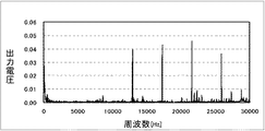
図6は、比較例に係るディスク駆動装置におけるコア振動の振動スペクトルを表すグラフである。横軸は周波数をHz単位で示し、縦軸は加速度センサ116からの出力電圧の周波数成分を任意の単位で示す。この出力電圧が高いほど振動の度合いも大きい。この振動スペクトルでは、12960Hzと、17280Hzと、21600Hzと、25920Hzにおいて振動の度合いが大きいこと分かる。
First, the present inventor manufactured a disk drive device according to a comparative example in which the
FIG. 6 is a graph showing a vibration spectrum of core vibration in the disk drive device according to the comparative example. The horizontal axis indicates the frequency in Hz, and the vertical axis indicates the frequency component of the output voltage from the
図6の振動スペクトルにおいて振動の度合いが大きい周波数について考察する。円筒状マグネット40の磁極数P=12極とし、コイル70を3相駆動する場合、各相の駆動電流の基本波の周波数F0は次の式1で表される。
F0=P・N/2=12極×120Hz/2=720Hz (式1)
したがって図6に示される振動スペクトルにおいて振動の度合いが大きい周波数はそれぞれ、基本波の周波数F0の18倍、24倍、30倍、36倍に相当する。即ち、比較例に係るディスク駆動装置の積層コアは、基本波の周波数F0の18倍、24倍、30倍、および36倍に相当する周波数のコア振動を生じている。この観察を一般化する。P極(Pは2以上の偶数)の駆動用着磁を有する円筒状マグネットを備えたディスク駆動装置に3相の駆動電流を供給して回転数N(Hz)で回転させた場合を想定する。この場合、振動スペクトルでは9PN(Hz)と、12PN(Hz)と、15PN(Hz)と、18PN(Hz)のうちの少なくともひとつの周波数において振動の度合いが、これら以外の周波数における振動の度合いと比べて大きくなると言える。したがって、振動スペクトルのうちのこれらの周波数成分を抑えることによってコア振動全体を効果的に低減できる。つまり、ディスク駆動装置の振動のうち、9PN(Hz)、12PN(Hz)、15PN(Hz)、および18PN(Hz)のうちの少なくともひとつの周波数に対応する成分を有意に小さくすると、例えばDC近傍の周波数に対応する成分よりも小さくすると、ディスク駆動装置の振動全体を効果的に低減できる。その結果、記録再生ヘッド8aの振動を低減してリード/ライトのエラーレートを改善できる。
Consider a frequency having a large degree of vibration in the vibration spectrum of FIG. When the number of magnetic poles P of the
F0 = P · N / 2 = 12 poles × 120 Hz / 2 = 720 Hz (Formula 1)
Therefore, in the vibration spectrum shown in FIG. 6, the frequencies having a large degree of vibration correspond to 18 times, 24 times, 30 times and 36 times the frequency F0 of the fundamental wave, respectively. That is, the laminated core of the disk drive device according to the comparative example generates core vibrations having frequencies corresponding to 18, 24, 30, and 36 times the fundamental frequency F0. Generalize this observation. A case is assumed in which a three-phase drive current is supplied to a disk drive device having a cylindrical magnet having a P-pole (P is an even number of 2 or more) drive magnet and rotated at a rotational speed N (Hz). . In this case, in the vibration spectrum, the degree of vibration is at least one of 9 PN (Hz), 12 PN (Hz), 15 PN (Hz), and 18 PN (Hz), and the degree of vibration at other frequencies. It can be said that it is larger than that. Therefore, by suppressing these frequency components in the vibration spectrum, the entire core vibration can be effectively reduced. That is, if the component corresponding to at least one frequency of 9 PN (Hz), 12 PN (Hz), 15 PN (Hz), and 18 PN (Hz) is significantly reduced in the vibration of the disk drive device, for example, near DC If the frequency is smaller than the component corresponding to the frequency of the disk drive, the overall vibration of the disk drive device can be effectively reduced. As a result, the read / write error rate can be improved by reducing the vibration of the recording / reproducing
また、駆動電流の交番周波数が大きくなると渦電流が大きくなることから、特に駆動電流の基本波の周波数F0がF0=PN/2>0.5kHz以上の場合にコア振動が顕著に大きくなることが確認された。 Further, since the eddy current increases as the alternating frequency of the drive current increases, the core vibration may be significantly increased particularly when the fundamental wave frequency F0 of the drive current is F0 = PN / 2> 0.5 kHz or more. confirmed.
本実施の形態に係るディスク駆動装置100では、積層コア60に含まれる電磁鋼板同士は、かしめ部66による固定に加えて、制振リング110によって軸方向にさらに強固に固定される。したがって、電磁鋼板の軸方向の動きが抑制され、層間力が生じても積層コア60のコア振動が抑制される。
In the
図7は、本実施の形態に係るディスク駆動装置100におけるコア振動の振動スペクトルを表すグラフである。横軸は周波数をHz単位で示し、縦軸は加速度センサ116からの出力電圧の周波数成分を図6と同じ単位で示す。この振動スペクトルに示される通り、本実施の形態に係るディスク駆動装置100では、基本波の周波数F0の18倍、24倍、30倍、36倍に相当するコア振動の成分が抑制されている。特にそれらの成分はDC近傍の周波数に対応する成分よりも小さい。このように本実施の形態に係るディスク駆動装置100ではコア振動が抑制されており、それによりリード/ライトのエラーレートが低減され、また信頼性が高められている。
FIG. 7 is a graph showing the vibration spectrum of the core vibration in the
また、本実施の形態に係るディスク駆動装置100では、制振リング110の外周面110aは、円環部62に対してモータ回転軸R方向において積層コア60の厚さT1の半分よりも長い長さに亘って圧入される。したがって、圧入長が短い、特に積層コア60の厚さT1の半分よりも短い場合と比べて、圧入による圧力によって積層コア60に含まれる電磁鋼板同士が軸方向においてより強固に固定される。その結果層間力によるコア振動が抑制される。
In the
この圧入長については、短くすると制振リング110による制振効果が不足しうる。また長くすると、圧入する際の抵抗が大きく圧入に手間がかかり、また積層コア60に変形を生じうる。このため圧入長は、磁気記録ディスク200の回転時におけるコア振動が許容される範囲に入るように、実験により定められてもよい。つまり、図5で説明された測定方法により、コア振動の振動スペクトルを測定する。そして測定された振動スペクトルの各成分、特に9PN(Hz)、12PN(Hz)、15PN(Hz)、および18PN(Hz)の周波数に対応する成分の大きさを確認しながら、圧入長を定めてもよい。
If the press-fitting length is shortened, the damping effect by the damping
また、一般に電磁鋼板を積層して形成するタイプの積層コアでは、個々の電磁鋼板の製造誤差などにより積層コアの側面には凹凸が見られる。この凸凹は、制振リングを積層コアの円環部に圧入する際の抵抗を増やす要因のひとつである考えられる。適正な圧入の際の抵抗を保つためには、凹凸によって増えた抵抗の分だけ圧入代を制限しなければならない。しかしながら積層コア60や制振リング110の加工上の寸法バラツキを考慮すると、そのような圧入代への制限は少ない方がよい。そこで本実施の形態に係るディスク駆動装置100では、制振リング110は積層コア60の電磁鋼板よりも柔らかい材料によって形成される。したがって、円環部62の内周面62aに凹凸が有ったとしても、それによる圧入の際の抵抗の増大を抑えることができ、圧入代を十分にとることができる。
Further, in a laminated core of a type generally formed by laminating electromagnetic steel sheets, irregularities are seen on the side surfaces of the laminated core due to manufacturing errors of individual electromagnetic steel sheets. This unevenness is considered to be one of the factors that increase the resistance when the damping ring is press-fitted into the annular portion of the laminated core. In order to maintain the resistance during proper press-fitting, it is necessary to limit the press-fitting allowance by the amount of resistance increased by the unevenness. However, in consideration of dimensional variations in processing of the
また、制振リング110の外周面110aを、円環部62の内周面62aの電磁鋼板層毎の凸凹に倣うように形成してもよい。この場合、圧入の際の抵抗の増大を抑えることができる。
本実施の形態において、積層コア60のビッカース硬度はHv120〜200の範囲とし、制振リング110のビッカース硬度はHv80〜100の範囲としている。
Moreover, you may form the outer
In the present embodiment, the Vickers hardness of the
また、本実施の形態に係るディスク駆動装置100では、かしめ部66は、径方向において、円環部62の内周面62aよりも突極64の端部64aに近い位置に形成される。したがって、突極64の端部側でコア振動をより低減できる。特に突極64の端部がベースプレート50に固定されていない本実施の形態に係るディスク駆動装置100のような構成においては、突極64の端部は大きなコア振動を起こしやすいと考えられる。そこでかしめ部66を端部側に設けることでそのようなコア振動を抑制できる。また、突極64の中間部分をかしめ部66と円環部62の内周面62aとで挟む構成となる。その結果、コア振動をさらに低減できる。
Further, in the
積層コア60の円環部62の半径方向の幅D1について考察する。ディスク駆動装置100全体の大きさは変えないでこの幅D1を大きくしていくと、突極64が短くなり、巻けるコイル70の巻数が減ることが考えられる。コイル70の巻数が減るとインダクタンスが低下するので、巻数を減らす前と同等の駆動トルクを保つためには駆動電流を増やす必要がある。しかしながら、駆動電流が増えると電気効率が低下し、また層間力が大きくなることでコア振動が増加する可能性がある。そこで本実施の形態に係るディスク駆動装置100では、積層コア60は、円環部62の径方向の幅D1が突極64のうちコイル70が巻き線される部分の周方向の幅D2よりも小さくなるように形成される。このように円環部62の径方向の幅D1を相対的に小さくすることで、駆動電流を相対的に低減してコア振動を抑制できる。
Consider the radial width D1 of the
また、積層コア60の円環部62は、突極64に巻回されたコイル70によって突極64に発生する磁束の経路となっている。特に突極64で発生した磁束は突極64の根元で円環部62の両側へ半分ずつ分岐する。したがって、円環部62の径方向の幅D1を狭くしすぎると、円環部62が磁気飽和して磁気抵抗が大きくなる場合がある。円環部62の磁気抵抗が大きくなると、突極64を通る磁束も減少する。したがって十分な駆動トルクを保つためには駆動電流を増やす必要がある。しかしながら、駆動電流が増えると電気効率が低下し、また層間力が大きくなることでコア振動が増加する可能性がある。そこで本実施の形態に係るディスク駆動装置100では、円環部62の径方向の幅D1が突極64のうちコイル70が巻き線される部分の周方向の幅D2の実質的に半分となるように設計される。これは上述の磁気飽和の観点から最適な設計であると考えられる。
Further, the
また、本実施の形態に係るディスク駆動装置100では、積層コア60は8枚の電磁鋼板を積層して形成される。積層コアを形成する電磁鋼板の枚数について、本発明者は以下の知見を得た。
コア振動は積層コアの電磁鋼板の枚数に応じて大きくなる傾向がある。個々の厚みが0.35mmの6枚以上の電磁鋼板を積層した積層コアに本実施の形態の思想を適用すると、コア振動をより抑制できるので好ましい。また電磁鋼板の枚数が多くなると、制振リングを圧入する際に必要な圧力が大きくなる。圧力が大きくなると積層コアを変形させうる。また、大きな力を要するため作業に時間がかかりうる。したがって、積層コアに含まれる電磁鋼板は20枚以下とすることが好ましい。
なお、厚みが0.2mmの電磁鋼板を使用する場合は、その電磁鋼板を8枚以上積層して形成される積層コアに本実施の形態の思想を適用すると、コア振動をより抑制できるので好ましい。また、上と同様の理由によりその枚数は30枚以下とすることが好ましい。
In the
The core vibration tends to increase according to the number of laminated steel sheets. It is preferable to apply the idea of the present embodiment to a laminated core obtained by laminating 6 or more electromagnetic steel sheets each having a thickness of 0.35 mm because the core vibration can be further suppressed. In addition, when the number of electromagnetic steel sheets increases, the pressure required for press-fitting the damping ring increases. When the pressure increases, the laminated core can be deformed. Moreover, since a large force is required, the work can take time. Therefore, it is preferable that the number of electromagnetic steel sheets included in the laminated core is 20 or less.
In addition, when using an electromagnetic steel sheet having a thickness of 0.2 mm, it is preferable to apply the idea of the present embodiment to a laminated core formed by laminating eight or more electromagnetic steel sheets, because the core vibration can be further suppressed. . For the same reason as above, the number is preferably 30 or less.
(第2の実施の形態)
第1の実施の形態では制振リング110を用いて積層コアの電磁鋼板間の結合を強める場合を説明した。第2の実施の形態は、制振リングを用いず突出部に直接積層コアを取り付けるタイプのディスク駆動装置に関する。第2の実施の形態に係るディスク駆動装置では、積層コアを突出部に取り付ける際に突出部を塑性変形させて円環部62に圧接させることで積層コアの電磁鋼板間の結合を強める。
(Second Embodiment)
1st Embodiment demonstrated the case where the coupling | bonding between the electromagnetic steel plates of a lamination | stacking core was strengthened using the damping
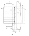
図8は、第2の実施の形態に係るディスク駆動装置400の断面の要部を拡大した拡大断面図である。図8は、第1の実施の形態の図3に対応する。説明を分かりやすくするため、図8ではかしめ部66を省略して表示する。ディスク駆動装置400のベースプレート450の上面には、モータ回転軸Rを中心とした突出部452が設けられる。その突出部452の外周面は、モータ回転軸Rを中心とする円筒状の側面452aである。この円筒状の側面452aは、円環部62の内周面62aにほぼ全面に亘って圧接される。円筒状の側面452aのうちその圧接に寄与する部分のモータ回転軸R方向長さL1は、積層コア60の厚さT1の半分よりも長い。ディスク駆動装置400のその他の構成は第1の実施の形態に係るディスク駆動装置100と同様である。
FIG. 8 is an enlarged cross-sectional view in which the main part of the cross section of the
積層コア60と突出部452との接合の方法を説明する。まずそれらを接合する前に、円環部62の内周面62aの半径を突出部452の側面452aの半径よりも大きく形成する。また、図8に示すように、突出部452の側面452aのうち台座454に連続する領域には半径方向内側に窪む凹部を形成してもよい。特に積層コア60を突出部452に隙間嵌めできるように形成すると、嵌め合わせ作業が容易になる点で好ましい。次に、積層コア60を突出部452の側面452aに沿って嵌め合わせる。積層コア60の下面をベースプレート450の台座454に突き当てて位置決めした後、突出部452のハブ10側の端部を例えばプレスして塑性変形させ、積層コア60の上側に図8のように延在させる。この延在部分により積層コア60はモータ回転軸R方向に固着される。またプレスの際、突出部452の側面452aは径方向外側に膨張するので、円環部62の内周面62aと圧接される。
A method of joining the
本実施の形態に係るディスク駆動装置400によると、制振リングを介さずに積層コア60を突出部452に固定する。したがって、第1の実施の形態に係るディスク駆動装置100と比べて、制振リング110を円環部62に対して圧入したり突出部52に固定したりする手間が省ける。
According to the
また、本実施の形態に係るディスク駆動装置400によると、積層コア60はモータ回転軸R方向においては突出部452の延在部分と台座454とに挟まれて固定され、また径方向においては突出部452の側面452aからの圧接による圧力によって固定される。したがってコア振動をより効果的に抑制できる。このコア振動の抑制という観点から見ると、径方向外側に膨張した突出部452の側面452aは、第1の実施の形態に係るディスク駆動装置100の制振リング110と同様の機能を有すると言える。
Further, according to the
なお、突出部452を形成する材料としてアルミニウムのような金属材料を採用すると経時変化による接合強度の低下が少ない点で好ましい。また、例えばポリエーテルイミドのような樹脂材料を採用すると形状の自由度が高く設計が容易である点で好ましい。
Note that it is preferable to use a metal material such as aluminum as a material for forming the protruding
以上、実施の形態に係るディスク駆動装置の構成について説明した。これらの実施の形態は例示であり、それらの各構成要素の組み合わせにいろいろな変形例が可能なこと、またそうした変形例も本発明の範囲にあることは当業者に理解されるところである。 The configuration of the disk drive device according to the embodiment has been described above. It is to be understood by those skilled in the art that these embodiments are exemplifications, and that various modifications can be made to combinations of the respective components, and such modifications are within the scope of the present invention.
第1および第2の実施の形態では、ベースプレートがハブを回転自在に支持する一体型のディスク駆動装置について説明したが、これに限られない。例えば、図2に示される構造と同様の構造のブラシレスモータを別途製作し、そのブラシレスモータをハードディスクドライブのシャーシに取り付けてもよい。 In the first and second embodiments, the integrated disk drive device in which the base plate rotatably supports the hub has been described. However, the present invention is not limited to this. For example, a brushless motor having the same structure as that shown in FIG. 2 may be manufactured separately, and the brushless motor may be attached to the hard disk drive chassis.
第1の実施の形態では、制振リング110の高さH1は積層コア60の厚さT1よりも小さく、また制振リング110はその高さH1全体に亘って円環部62に対して圧入される場合について説明したが、これに限られない。以下に制振リング110の変形例を2つ説明する。
図9は、第1変形例に係る制振リング510を含むディスク駆動装置500の断面の要部を拡大した拡大断面図である。図9は、第1の実施の形態の図3に対応する。説明を分かりやすくするため、図9ではかしめ部66を省略して表示する。制振リング510は、第1の実施の形態に係る制振リング110の外周面のモータ回転軸R方向中央付近に、モータ回転軸Rを中心とする幅D3の環状の凹部512を設けたものである。この制振リング510を円環部62に圧入した場合、制振リング510の外周面510aと円環部62との圧入部分には、制振リング510の外周面510aが円環部62の内周面62aに圧接する第1部分514、第2部分516に挟まれた、それらが接触しない第3部分518が設けられる。
In the first embodiment, the height H1 of the damping
FIG. 9 is an enlarged cross-sectional view in which a main part of a cross section of the
本変形例に係るディスク駆動装置500によると、第1の実施の形態に係るディスク駆動装置100と同様に、制振リング510の外周面510aは少なくとも、モータ回転軸R方向において、積層コア60の下面60aよりも積層コア60の上面60bに近い位置で円環部62の内周面62aに圧接されている。したがって、第1の実施の形態で説明したようにコア振動を低減できる。また、積層コア60は第1部分514および第2部分516によって挟み込まれるようにして固定されるので、制振リングの外周面の全面が圧入に寄与する場合と比べて遜色ない強度の固定を実現できる。さらに本変形例では、第1の実施の形態とは異なり、環状の凹部512に対応する部分は圧入に寄与しない。したがって、圧入の際の抵抗を低減できる。なお、環状の凹部は複数設けられてもよい。さらに、環状の凹部ではなくモータ回転軸R方向に沿った凹部を制振リング110の外周面110aに設けてもよい。
According to the
図10は、第2変形例に係る制振リング610を含むディスク駆動装置600の断面の要部を拡大した拡大断面図である。図10は、第1の実施の形態の図3に対応する。説明を分かりやすくするため、図10ではかしめ部66を省略して表示する。制振リング610は、第1の実施の形態に係る制振リング110の外周面に、半径を低減した幅D4のニゲ部612を設けたものである。この制振リング610を円環部62に圧入した場合、制振リング610の外周面610aのうちニゲ部612に対応する幅D4の部分は圧入に寄与しない。
FIG. 10 is an enlarged cross-sectional view of an enlarged main part of the cross section of the
本変形例に係るディスク駆動装置600によると、第1の実施の形態に係るディスク駆動装置100と同様に、制振リング610の外周面610aは少なくとも、モータ回転軸R方向において、積層コア60の下面60aよりも積層コア60の上面60bに近い位置で円環部62の内周面62aに圧接されている。したがって、第1の実施の形態で説明したようにコア振動を低減できる。さらに本変形例では、第1の実施の形態とは異なり、ニゲ部612に対応する部分は圧入に寄与しない。したがって、圧入の際の抵抗を低減できる。
According to the
ここで、圧入長が短いほど圧入に要する圧力は少なくて済むので、作業性だけを考えるとモータ回転軸R方向に長くニゲ部612を設けたほうが良いと考えられる。しかしながら、積層コア60と制振リング610とが圧入されている部分のモータ回転軸R方向幅D5があまりにも短い場合には、積層コア60を抑える力が小さくなり過ぎるおそれがある。そこで本発明者は実験を行い、D5/T1が1/3以上あることが、コア振動を抑える観点から好ましいことを確認した。
Here, the shorter the press-fitting length, the smaller the pressure required for press-fitting. Therefore, considering only the workability, it is considered better to provide the
第1の実施の形態、その変形例、および第2の実施の形態に係るディスク駆動装置では、積層コア60の厚さT1に対する、積層コア60を機械的に固定している接合部のモータ回転軸R方向両端間の長さの比を1/2以上としている、とも言える。
In the disk drive device according to the first embodiment, its modified example, and the second embodiment, the motor rotation of the joint that mechanically fixes the
第1および第2の実施の形態では、積層コア60の下面60aがベースプレートの台座に突き当てられる場合について説明したが、積層コア60は台座に突き当てられなくてもよい。この場合でも、制振リングの圧入による圧力でコア振動を抑制できる。
In the first and second embodiments, the case where the
第1および第2の実施の形態において、積層コア60をベースプレート50に取り付けた後、それらを洗浄してもよい。この場合、圧入の際に生じうる剥離物を除去することができる。
In 1st and 2nd embodiment, after attaching the lamination | stacking
第1の実施の形態では、制振リング110を積層コア60の電磁鋼板よりも柔らかい材料によって形成することで、円環部62の内周面62aの凹凸に起因して生じうる圧入抵抗を低減する場合について説明したが、これに限られない。例えば、積層コア60の円環部62の内周面62aに凸凹を緩和し、潤滑性を向上させるための潤滑層702を形成してもよい。図11は、第3変形例に係るディスク駆動装置700の断面の要部を拡大した拡大断面図である。図11は、第1の実施の形態の図3に対応する。説明を分かりやすくするため、図11ではかしめ部66を省略して表示する。円環部62の内周面には、その凹凸を覆うように潤滑層702が設けられる。
In the first embodiment, the damping
この潤滑層702は、例えばエポキシ樹脂をスプレー塗装する方法や、カチオン電着を用いる方法により形成される。この場合、均一な塗膜を得られる。
なお、潤滑層702が薄い場合には、潤滑層702の厚みのバラツキの影響が相対的に大きくなり部分的に十分な潤滑性が得られないことがある。実験によると潤滑層702の厚みが20μm以上の場合に安定して所望の精度で圧入できることが確認された。すなわち、潤滑層702の厚みが圧入代の半分以上の場合に所望の効果が得られることが確認された。また、潤滑層702が厚いと圧入の際に潤滑層702が削れる可能性がある。潤滑層702が不均一に削れると圧入の精度が悪化しうる。実験によると潤滑層702の厚みが80μm以下の場合には圧入の精度の悪化は見られなかった。すなわち、潤滑層702の厚みは圧入代の設定しうる最大値以下の場合には所望の圧入の精度が得られることを確認した。
なお、潤滑層702は積層コア60の表面処理と同時に形成してもよい。作業の手間が省ける点で好ましい。また、潤滑層702は別途形成してもよい。所望の潤滑性を確保しやすい点で好ましい。
The
In addition, when the
The
第1および第2の実施の形態では、マグネットが積層コアの外側に位置する、いわゆるアウターロータ型のディスク駆動装置について説明したが、これに限られない。たとえばマグネットが積層コアの内側に位置する、いわゆるインナーロータ型のディスク駆動装置であってもよい。 In the first and second embodiments, the so-called outer rotor type disk drive device in which the magnet is located outside the laminated core has been described. However, the present invention is not limited to this. For example, it may be a so-called inner rotor type disk drive device in which a magnet is positioned inside a laminated core.
第1および第2の実施の形態では、スリーブがベースプレートに固定され、シャフトがスリーブに対して回転する場合について説明したが、たとえばシャフトがベースプレートに固定され、スリーブがハブと共にシャフトに対して回転するようなシャフト固定型であってもよい。 In the first and second embodiments, the case where the sleeve is fixed to the base plate and the shaft rotates relative to the sleeve has been described. For example, the shaft is fixed to the base plate, and the sleeve rotates relative to the shaft together with the hub. Such a shaft fixed type may be used.
第1および第2の実施の形態は主にハードディスクドライブに用いられる場合について説明したが、これに限られない。例えば、図2に示される構造のブラシレスモータを製作し、そのブラシレスモータをCD(Compact Disc)装置、DVD(Digital Versatile Disc)装置等の光学ディスク記録再生装置に搭載してもよい。 Although the first and second embodiments have been described mainly for use in a hard disk drive, the present invention is not limited to this. For example, a brushless motor having the structure shown in FIG. 2 may be manufactured, and the brushless motor may be mounted on an optical disk recording / reproducing device such as a CD (Compact Disc) device or a DVD (Digital Versatile Disc) device.
以上、実施の形態にもとづき本発明を説明したが、実施の形態は、本発明の原理、応用を示しているにすぎないことはいうまでもなく、実施の形態には、請求の範囲に規定された本発明の思想を逸脱しない範囲において、多くの変形例や配置の変更が可能であることはいうまでもない。 Although the present invention has been described based on the embodiments, the embodiments merely show the principle and application of the present invention, and the embodiments are defined in the claims. Needless to say, many modifications and arrangements can be made without departing from the spirit of the present invention.
8 データリード/ライト部、 10 ハブ、 20 シャフト、 22 フランジ、 30 ヨーク、 40 円筒状マグネット、 50 ベースプレート、 52 突出部、 60 積層コア、 62 円環部、 64 突極、 66 かしめ部、 70 コイル、 80 スリーブ、 90 プレート、 92 潤滑剤、 100、300、400、500、600 ディスク駆動装置、 110 制振リング、 116 加速度センサ、 118 FFTアナライザ、 200 磁気記録ディスク、 R モータ回転軸。 8 data read / write section, 10 hub, 20 shaft, 22 flange, 30 yoke, 40 cylindrical magnet, 50 base plate, 52 projecting section, 60 laminated core, 62 annular section, 64 salient pole, 66 caulking section, 70 coil , 80 sleeve, 90 plate, 92 lubricant, 100, 300, 400, 500, 600 disk drive device, 110 damping ring, 116 acceleration sensor, 118 FFT analyzer, 200 magnetic recording disk, R motor rotating shaft.
Claims (6)
前記ハブを回転自在に支持する流体動圧軸受と、
前記ハブ側の面に、前記ハブの回転軸を中心とする円筒状の外周側の側面を有し、前記流体動圧軸受が接着固定される軸受固定突出部が設けられたベースと、
鋼板を積層して形成され、円環部とそこから半径方向に伸びる複数の突極とを含む積層コアと、
前記複数の突極に巻き線されて形成されるコイルと、
前記ハブに固定され、前記複数の突極と半径方向に対向し、周方向に複数の駆動用着磁が施されたマグネットと、を備え、
前記複数の突極のうちの少なくともひとつは、前記積層コアの前記鋼板間に亘るハーフパンチ状態のかしめ部を含み、
前記軸受固定突出部の前記側面は半径方向外側に膨張して前記円環部に圧接される圧接部分を有することを特徴とするディスク駆動装置。 A hub on which the recording disk should be placed;
A fluid dynamic bearing for rotatably supporting the front Symbol hub,
The surface of the hub side, have a cylindrical outer peripheral side surface of the around the rotation axis of the hub, a base bearing the fixed projecting portion is provided that the fluid dynamic bearing is bonded and fixed,
A laminated core that is formed by laminating steel plates and includes an annular portion and a plurality of salient poles extending radially from the annular portion;
A coil formed by being wound around the plurality of salient poles;
A magnet fixed to the hub, opposed to the plurality of salient poles in the radial direction, and provided with a plurality of drive magnetizations in the circumferential direction;
At least one of the plurality of salient poles includes a caulking portion in a half punch state between the steel plates of the laminated core,
The disk drive device according to claim 1, wherein the side surface of the bearing fixing protrusion has a pressure contact portion that expands radially outward and is pressed against the annular portion.
前記ベースは、前記軸受固定突出部の前記側面から半径方向外側に延在して前記円環部の端面が突き当たる台座を有し、
前記積層コアは、前記円環部が前記台座と前記延在部との間に挟まれることを特徴とする請求項1から4のいずれかに記載のディスク駆動装置。 The bearing fixing protrusions have a extending portion extending from the said hub-side end to the hub-side end face of the annular portion,
The base has a pedestal that extends radially outward from the side surface of the bearing fixing protrusion and abuts the end surface of the annular portion,
The laminated core is a disk drive device according to any one of claims 1 to 4, sandwiched characterized Rukoto between said annular portion said base and said extension portion.
Priority Applications (3)
| Application Number | Priority Date | Filing Date | Title |
|---|---|---|---|
| JP2009243252A JP5513070B2 (en) | 2009-10-22 | 2009-10-22 | Disk drive |
| US12/871,508 US8451557B2 (en) | 2009-10-22 | 2010-08-30 | Disk drive device having a vibration-reducing element |
| US13/850,007 US8902542B2 (en) | 2009-10-22 | 2013-03-25 | Disk drive device having a projecting portion and a mounted laminated core |
Applications Claiming Priority (1)
| Application Number | Priority Date | Filing Date | Title |
|---|---|---|---|
| JP2009243252A JP5513070B2 (en) | 2009-10-22 | 2009-10-22 | Disk drive |
Publications (3)
| Publication Number | Publication Date |
|---|---|
| JP2011090739A JP2011090739A (en) | 2011-05-06 |
| JP2011090739A5 JP2011090739A5 (en) | 2012-10-11 |
| JP5513070B2 true JP5513070B2 (en) | 2014-06-04 |
Family
ID=43898237
Family Applications (1)
| Application Number | Title | Priority Date | Filing Date |
|---|---|---|---|
| JP2009243252A Expired - Fee Related JP5513070B2 (en) | 2009-10-22 | 2009-10-22 | Disk drive |
Country Status (2)
| Country | Link |
|---|---|
| US (2) | US8451557B2 (en) |
| JP (1) | JP5513070B2 (en) |
Families Citing this family (13)
| Publication number | Priority date | Publication date | Assignee | Title |
|---|---|---|---|---|
| JP5513070B2 (en) * | 2009-10-22 | 2014-06-04 | サムスン電機ジャパンアドバンスドテクノロジー株式会社 | Disk drive |
| US8917479B2 (en) * | 2012-11-23 | 2014-12-23 | Seagate Technology Llc | Harmonic shaping of a motor |
| DE102014206848A1 (en) * | 2014-04-09 | 2015-10-15 | Zf Friedrichshafen Ag | Assembly with a laminated laminated core for an electrical machine, method for producing such a structural unit and electrical machine |
| KR101628142B1 (en) * | 2014-11-10 | 2016-06-09 | 현대자동차 주식회사 | Stator assembly structure for drive motor of hybrid electric vehicle |
| JP2016123230A (en) * | 2014-12-25 | 2016-07-07 | 日本電産株式会社 | Spindle motor, and disk drive |
| JP6515533B2 (en) | 2014-12-26 | 2019-05-22 | 日本電産株式会社 | Spindle motor and disk drive |
| DE102015011340A1 (en) * | 2015-09-03 | 2017-03-09 | Minebea Co., Ltd. | Stator for an electric machine |
| JP6661240B2 (en) * | 2016-08-31 | 2020-03-11 | 株式会社ミツバ | Motor device |
| JP2018068005A (en) * | 2016-10-18 | 2018-04-26 | 日本電産株式会社 | Motor and disk drive unit |
| DE102017105414A1 (en) | 2017-03-14 | 2018-09-20 | Minebea Mitsumi Inc. | electric motor |
| JP2019062631A (en) * | 2017-09-26 | 2019-04-18 | 日本電産株式会社 | motor |
| JP6957631B2 (en) * | 2017-09-27 | 2021-11-02 | 三菱電機株式会社 | Rotating machine |
| EP3930150A4 (en) * | 2019-02-20 | 2022-11-16 | Nidec Corporation | Stator core, rotor core, and motor |
Family Cites Families (26)
| Publication number | Priority date | Publication date | Assignee | Title |
|---|---|---|---|---|
| JP2937621B2 (en) * | 1992-04-20 | 1999-08-23 | 株式会社三協精機製作所 | Motor core winding set |
| JPH07210981A (en) * | 1994-01-07 | 1995-08-11 | Sankyo Seiki Mfg Co Ltd | Magnetic disk driving device |
| US5548458A (en) * | 1994-05-04 | 1996-08-20 | Seagate Technology, Inc. | Support flange having electrical contacts to provide electrical continuity upon spindle motor mounting to base |
| JP3282406B2 (en) * | 1994-09-30 | 2002-05-13 | 富士通株式会社 | Rotary drive device and storage device |
| US5757101A (en) * | 1995-06-06 | 1998-05-26 | International Business Machines Corporation | Laminated back iron structrue for increased motor efficiency |
| JP3718541B2 (en) * | 1995-07-13 | 2005-11-24 | ファナック株式会社 | Vertical rotor |
| DE19733566B4 (en) * | 1997-08-02 | 2005-10-13 | Minebea Co., Ltd. | Spindle motor with sleeve |
| JP2000037064A (en) * | 1998-07-17 | 2000-02-02 | Tdk Corp | Spindle motor |
| JP2000163859A (en) * | 1998-11-24 | 2000-06-16 | Fujitsu Ltd | Recording disk driving device and spindle motor |
| US6753628B1 (en) * | 1999-07-29 | 2004-06-22 | Encap Motor Corporation | High speed spindle motor for disc drive |
| JP2001050278A (en) * | 1999-08-04 | 2001-02-23 | Sankyo Seiki Mfg Co Ltd | Manufacture of dynamic-pressure bearing device, and dynamic-pressure bearing device |
| US6809898B1 (en) * | 2000-01-13 | 2004-10-26 | Maxtor Corporation | Disk drive rocking mode vibration damper |
| JP2002171701A (en) * | 2000-11-30 | 2002-06-14 | Seiko Instruments Inc | Spindle motor |
| JP2005181715A (en) * | 2003-12-19 | 2005-07-07 | Canon Inc | Deflective scanner |
| JP4823585B2 (en) * | 2004-09-29 | 2011-11-24 | 株式会社デンソー | Magnet generator |
| US7327066B2 (en) * | 2005-03-01 | 2008-02-05 | Nidec Corporation | Motor and recording disk drive device provided with the same |
| JP2007213629A (en) | 2006-02-07 | 2007-08-23 | Nippon Densan Corp | Rotor hub, motor and recording disk driving device |
| JP2007210981A (en) | 2006-02-13 | 2007-08-23 | Atomu Japan:Kk | Plant-rooting stabilizer |
| JP2007323784A (en) * | 2006-06-05 | 2007-12-13 | Hitachi Ltd | Disk device |
| JP2008148469A (en) * | 2006-12-12 | 2008-06-26 | Hitachi Ltd | Spindle motor, disk driving device and manufacturing method of stator core |
| JP5216267B2 (en) * | 2007-07-30 | 2013-06-19 | 株式会社ミツバ | Armature manufacturing method |
| JP5513070B2 (en) * | 2009-10-22 | 2014-06-04 | サムスン電機ジャパンアドバンスドテクノロジー株式会社 | Disk drive |
| US8476802B2 (en) * | 2010-06-16 | 2013-07-02 | Samsung Electro-Mechanics Co., Ltd. | Core and motor having the same |
| JP2012055075A (en) * | 2010-08-31 | 2012-03-15 | Nippon Densan Corp | Spindle motor and disk drive device |
| JP2013046455A (en) * | 2011-08-23 | 2013-03-04 | Nippon Densan Corp | Spindle motor and disk drive device |
| US20130099623A1 (en) * | 2011-10-25 | 2013-04-25 | Minebea Motor Manufacturing Corporation | Disk rotating motor and disk drive device provided with the same |
-
2009
- 2009-10-22 JP JP2009243252A patent/JP5513070B2/en not_active Expired - Fee Related
-
2010
- 2010-08-30 US US12/871,508 patent/US8451557B2/en not_active Expired - Fee Related
-
2013
- 2013-03-25 US US13/850,007 patent/US8902542B2/en not_active Expired - Fee Related
Also Published As
| Publication number | Publication date |
|---|---|
| US8902542B2 (en) | 2014-12-02 |
| US20110096437A1 (en) | 2011-04-28 |
| US20130222946A1 (en) | 2013-08-29 |
| JP2011090739A (en) | 2011-05-06 |
| US8451557B2 (en) | 2013-05-28 |
Similar Documents
| Publication | Publication Date | Title |
|---|---|---|
| JP5513070B2 (en) | Disk drive | |
| JP5166323B2 (en) | Disk drive device and production method thereof | |
| JP5519314B2 (en) | Rotating equipment | |
| JP2012023944A (en) | Rotary apparatus | |
| US8345379B2 (en) | Disk drive device equipped with a bearing unit relatively rotatably supporting a hub against base member | |
| JP2014033487A (en) | Rotary device | |
| US20120049680A1 (en) | Rotating device having rotor, stator, and driving mechanism | |
| US8213113B2 (en) | Disk drive device with vibration reduction of second order rocking-mode resonance | |
| US8845194B2 (en) | Rotary device | |
| US7511398B2 (en) | Motor and recording disk driving device | |
| US6921993B2 (en) | Geometrically aligning a stator and a base plate for a spindle motor | |
| US8913343B2 (en) | Rotating device using a fluid dynamic bearing with magnet and suction plate | |
| JP5455835B2 (en) | Rotating body for fluid dynamic pressure bearing and manufacturing method of rotating body for fluid dynamic pressure bearing | |
| JP2011176916A (en) | Magnetizer, rotating machine and method of manufacturing the rotating machine | |
| JP5210054B2 (en) | Motor and disk drive using the same | |
| US20140334036A1 (en) | Rotating device | |
| JP2014082349A (en) | Magnetization device, method of manufacturing rotary apparatus and rotary apparatus | |
| JP2016208676A (en) | Rotary apparatus and production method of rotary apparatus | |
| JP2010088235A (en) | Stator, motor and recording medium drive device | |
| JP4580467B1 (en) | Disk drive | |
| JP2015104289A (en) | Rotary apparatus | |
| JP5729789B2 (en) | Fluid dynamic bearing | |
| JP2006271043A (en) | Motor and recording medium drive unit | |
| US8976486B2 (en) | Rotating device with hub and yoke having radial extension portion | |
| JP2014116058A (en) | Spindle motor and hard disk drive including the same |
Legal Events
| Date | Code | Title | Description |
|---|---|---|---|
| RD02 | Notification of acceptance of power of attorney |
Free format text: JAPANESE INTERMEDIATE CODE: A7422 Effective date: 20120828 |
|
| A521 | Written amendment |
Free format text: JAPANESE INTERMEDIATE CODE: A523 Effective date: 20120829 |
|
| A621 | Written request for application examination |
Free format text: JAPANESE INTERMEDIATE CODE: A621 Effective date: 20120829 |
|
| A977 | Report on retrieval |
Free format text: JAPANESE INTERMEDIATE CODE: A971007 Effective date: 20131024 |
|
| A131 | Notification of reasons for refusal |
Free format text: JAPANESE INTERMEDIATE CODE: A131 Effective date: 20131029 |
|
| TRDD | Decision of grant or rejection written | ||
| A01 | Written decision to grant a patent or to grant a registration (utility model) |
Free format text: JAPANESE INTERMEDIATE CODE: A01 Effective date: 20140325 |
|
| A61 | First payment of annual fees (during grant procedure) |
Free format text: JAPANESE INTERMEDIATE CODE: A61 Effective date: 20140327 |
|
| R150 | Certificate of patent or registration of utility model |
Ref document number: 5513070 Country of ref document: JP Free format text: JAPANESE INTERMEDIATE CODE: R150 |
|
| LAPS | Cancellation because of no payment of annual fees |