JP6515533B2 - Spindle motor and disk drive - Google Patents
Spindle motor and disk drive Download PDFInfo
- Publication number
- JP6515533B2 JP6515533B2 JP2014266518A JP2014266518A JP6515533B2 JP 6515533 B2 JP6515533 B2 JP 6515533B2 JP 2014266518 A JP2014266518 A JP 2014266518A JP 2014266518 A JP2014266518 A JP 2014266518A JP 6515533 B2 JP6515533 B2 JP 6515533B2
- Authority
- JP
- Japan
- Prior art keywords
- wire
- core back
- spindle motor
- fixing member
- coil
- Prior art date
- Legal status (The legal status is an assumption and is not a legal conclusion. Google has not performed a legal analysis and makes no representation as to the accuracy of the status listed.)
- Expired - Fee Related
Links
Images


Classifications
-
- H—ELECTRICITY
- H02—GENERATION; CONVERSION OR DISTRIBUTION OF ELECTRIC POWER
- H02K—DYNAMO-ELECTRIC MACHINES
- H02K3/00—Details of windings
- H02K3/04—Windings characterised by the conductor shape, form or construction, e.g. with bar conductors
- H02K3/28—Layout of windings or of connections between windings
-
- G—PHYSICS
- G11—INFORMATION STORAGE
- G11B—INFORMATION STORAGE BASED ON RELATIVE MOVEMENT BETWEEN RECORD CARRIER AND TRANSDUCER
- G11B17/00—Guiding record carriers not specifically of filamentary or web form, or of supports therefor
- G11B17/02—Details
-
- G—PHYSICS
- G11—INFORMATION STORAGE
- G11B—INFORMATION STORAGE BASED ON RELATIVE MOVEMENT BETWEEN RECORD CARRIER AND TRANSDUCER
- G11B19/00—Driving, starting, stopping record carriers not specifically of filamentary or web form, or of supports therefor; Control thereof; Control of operating function ; Driving both disc and head
- G11B19/20—Driving; Starting; Stopping; Control thereof
- G11B19/2009—Turntables, hubs and motors for disk drives; Mounting of motors in the drive
-
- H—ELECTRICITY
- H02—GENERATION; CONVERSION OR DISTRIBUTION OF ELECTRIC POWER
- H02K—DYNAMO-ELECTRIC MACHINES
- H02K3/00—Details of windings
- H02K3/46—Fastening of windings on the stator or rotor structure
- H02K3/52—Fastening salient pole windings or connections thereto
- H02K3/521—Fastening salient pole windings or connections thereto applicable to stators only
- H02K3/522—Fastening salient pole windings or connections thereto applicable to stators only for generally annular cores with salient poles
-
- H—ELECTRICITY
- H02—GENERATION; CONVERSION OR DISTRIBUTION OF ELECTRIC POWER
- H02K—DYNAMO-ELECTRIC MACHINES
- H02K2203/00—Specific aspects not provided for in the other groups of this subclass relating to the windings
- H02K2203/06—Machines characterised by the wiring leads, i.e. conducting wires for connecting the winding terminations
Description
本発明は、スピンドルモータ、およびディスク駆動装置に関する。 The present invention relates to a spindle motor and a disk drive.
ハードディスクドライブなどのディスク駆動装置は、記録ディスクを回転させるスピンドルモータを備える。特許文献1に記載されたステータコアアセンブリーは、固定部材に挿入されて結合されるコアバックと、上記コアバックから突設しコイルが巻回される少なくとも1つのティース部と、を含む。コイルの渡り線は、コアバックに配置される。ティース部に巻回された後の引き出し線は、ティース部の軸方向下部を通る。
A disk drive such as a hard disk drive includes a spindle motor that rotates a recording disk. The stator core assembly described in
特許文献1のコイルは、ティース部に反時計回りにm回巻回される。その後、引き出し線は、ティース部の軸方向下部に引き出される。引き出し線がゆるんでしまうと、引き出し線がコイルより上方に位置し、引き出し線が回転部材と接触してしまう。引き出し線が回転部材に接触してしまうと、引き出し線が損傷し、さらには断線してしまう虞がある。
また、特許文献1の渡り線は、コアバックに配置される。渡り線がコアバックの内側領域に位置すると、ステータコアアセンブリーを固定部材に結合しようとする際、渡り線を噛み込んでしまう虞がある。
The coil of
Moreover, the crossover of
本発明の一つの態様は、コイルの引き出し線および渡り線が移動することを抑制できるスピンドルモータ、およびディスク駆動装置を提供することを目的の一つとする。 An object of one aspect of the present invention is to provide a spindle motor and a disk drive capable of suppressing movement of the lead wire and the crossover wire of the coil.
本開示の一態様によれば、静止部と、前記静止部に対し上下に延びる中心軸を中心に回転する回転部と、を備え、前記静止部は、環状のコアバックと前記コアバックから径方向外側に延びる複数のティース部とを有するステータコア、および前記複数のティース部に巻かれたコイルを有するステータ部と、前記コアバックの内側面に圧入される外側面と、を有し、前記コイルを構成する巻線は、前記コイル同士を接続する渡り線と、前記コイルから引き出され、前記ティース部の上面側から下面側に引き出される引出線と、を含み、前記渡り線および前記引出線は、前記コアバックの内側面よりも径方向外側に位置し、少なくとも前記コアバックの上面に位置する固定部材を有し、前記固定部材は、前記渡り線の少なくとも一部、および前記引出線の少なくとも一部を前記ステータコアに固定する、スピンドルモータが提供される。 According to one aspect of the present disclosure, a stationary unit, and a rotating unit that rotates around a central axis extending up and down with respect to the stationary unit, the stationary unit having a diameter from an annular core back and the core back A stator core having a plurality of teeth extending in an outward direction, a stator having a coil wound around the plurality of teeth, and an outer surface press-fit to an inner surface of the core back, The winding constituting the coil includes a crossover connecting the coils, and a lead drawn from the coil and drawn from the upper surface side to the lower surface of the tooth portion, the crossover and the lead wire A fixing member positioned radially outward of the inner surface of the core back and positioned at least on the upper surface of the core back, the fixing member including at least a portion of the crossover, and At least a portion of the output line is fixed to the stator core, the spindle motor is provided.
本開示の一態様によれば、コイルの引出線および渡り線が移動することを抑制できるスピンドルモータ、およびディスク駆動装置を提供できる。 According to one aspect of the present disclosure, it is possible to provide a spindle motor and a disk drive capable of suppressing movement of the lead wire and the crossover wire of the coil.
以下、図面を参照しながら、好ましい実施形態について説明する。なお、本発明の範囲は、以下の実施の形態に限定されるものではなく、本発明の技術的思想の範囲内で任意に変更可能である。また、以下の図面においては、各構成をわかりやすくするために、実際の構造と各構造における縮尺や数等と、を異ならせる場合がある。 Hereinafter, preferred embodiments will be described with reference to the drawings. The scope of the present invention is not limited to the following embodiments, and can be arbitrarily changed within the scope of the technical idea of the present invention. Moreover, in the following drawings, in order to make each structure intelligible, the scale, the number, etc. in an actual structure and each structure may be made different.
以下の図面においては、適宜3次元直交座標系としてXYZ座標系を示す。XYZ座標系において、Z軸方向は、図1に示す上下方向に延びる中心軸Jと平行な方向とする。Y軸方向は、Z軸に直交する方向とする。X軸方向は、Z軸、およびY軸に直交する方向とする。なお、「平行な方向」とは略平行な方向も含む。また、「直交」とは、略直交も含む。 In the following drawings, an XYZ coordinate system is shown as a three-dimensional orthogonal coordinate system as appropriate. In the XYZ coordinate system, the Z-axis direction is a direction parallel to the central axis J extending in the vertical direction shown in FIG. The Y-axis direction is a direction orthogonal to the Z-axis. The X-axis direction is a direction orthogonal to the Z-axis and the Y-axis. The “parallel direction” also includes a substantially parallel direction. Moreover, "orthogonal" also includes substantially orthogonal.
また、以下の説明においては、Z軸方向の正の側(+Z側)を「上側」と記し、Z軸方向の負の側(−Z側)を「下側」と記す。なお、上下方向は、実際の機器に組み込まれたときの位置関係や方向を示すものではない。また、以下の説明においては、中心軸Jを基準に位置関係や位置を規定する。特に断りのない限り、中心軸Jと平行な方向(Z軸方向)を単に「軸方向」と記し、中心軸Jを中心とする径方向を単に「径方向」と記し、中心軸Jを中心とする周方向を単に「周方向」と記す。 Further, in the following description, the positive side (+ Z side) in the Z-axis direction is described as "upper side", and the negative side (-Z side) in the Z-axis direction is described as "lower side". Note that the vertical direction does not indicate the positional relationship or direction when it is incorporated into an actual device. Further, in the following description, the positional relationship and the position are defined with reference to the central axis J. Unless otherwise noted, a direction parallel to the central axis J (Z-axis direction) is simply described as “axial direction”, a radial direction centered on the central axis J is simply described as “radial direction”, and the central axis J is centered The circumferential direction to be taken is simply referred to as "circumferential direction".
図1は、好ましい実施形態におけるスピンドルモータ1を備えるディスク駆動装置100を示す縦断面図である。
ディスク駆動装置100は、ハードディスクドライブである。ディスク駆動装置100は、スピンドルモータ1と、ディスク101と、アクセス部102と、を有する。スピンドルモータ1は、情報を記録するディスク101を中心軸J周りに回転させる。アクセス部102は、ディスク101に対して情報の読み出しおよび書き込みの少なくともいずれか一方を行う。
FIG. 1 is a longitudinal sectional view showing a
The
ディスク駆動装置100は、ハウジング103を有する。ハウジング103は、スピンドルモータ1のベース部40と、カバー部材104と、を含む。ベース部40の開口にカバー部材104が嵌められて、ハウジング103が構成される。ハウジング103には、ディスク101およびアクセス部102が収容される。ハウジング103には、例えば、ヘリウムガスが充填されている。なお、ハウジング103には、水素ガス、空気等が充填されていてもよい。
The
ディスク駆動装置100は、ディスク101を複数有する。ディスク駆動装置100は、ディスク101の間に配置されるスペーサ105を有する。複数のディスク101は、スピンドルモータ1に支持される。具体的には、スピンドルモータ1の回転部10に支持される。回転部10は、複数のディスク101を支持するクランプ部材11を有する。ディスク駆動装置100は、クランプ部材11とディスク101との間に配置されるスペーサ106を有する。複数のディスク101は、回転部10と共に中心軸J周りに回転する。
The
アクセス部102は、ヘッド107と、アーム108と、ヘッド移動機構109と、を有する。ヘッド107は、ディスク101の表面に接近して情報の読み出しおよび書き込みの少なくともいずれか一方を磁気的に行う。ヘッド107は、アーム108に支持される。アーム108は、ヘッド移動機構109に支持される。
The
スピンドルモータ1は、静止部2と、静止部2に対して上下に延びる中心軸Jを中心に回転する回転部10と、を有する。静止部2は、後述する外側面41bと、軸受部20のシャフト21と、ステータ部30と、ベース部40と、配線基板50と、を有する。回転部10は、軸受部20のスリーブ22と、クランプ部材11と、ロータハブ12と、ロータマグネット13と、を有する。
The
軸受部20は、ロータハブ12を中心軸J周りに回転可能に支持する。軸受部20は、シャフト21と、スリーブ22と、を有する。シャフト21は、ベース部40に対して固定される。シャフト21とスリーブ22とは、隙間を介し対向する。隙間には、潤滑油または気体が介在する。
The
ステータ部30は、コイル31と、ステータコア32と、を有する。コイル31は、ロータマグネット13と隙間を介し対向する。ステータコア32は、磁性体を複数積層した積層構造体である。ステータコア32は、環状のコアバック33と、複数のティース部34と、を有する。複数のティース部34は、コアバック33から径方向外側に延びる。複数のティース部34には、コイル31が巻かれる。
The
ベース部40は、上面40Aと下面40Bとを有する。ベース部40は、ステータ部30を上面40Aに支持する。上面40Aは、ハウジング103の内側を向く面である。ベース部40は、円筒部41と、ベース部貫通孔42と、を有する。円筒部41は、ベース部40の上面40Aに配置される。円筒部41は、好ましくは軸方向に延びる筒状である。前述の通り静止部2は外側面41bを有し、より具体的には円筒部41は、コアバック33の内側面33aに圧入される外側面41bを有する。外側面41bを構成する静止部2の壁面は、以下、円筒部41の外側面41bと記す。なお、円筒部41は、筒状に限らず、例えば多角形状等でもよい。また、内側面33aは、環状の周面に限らず、例えば多角形状等でもよい。
The
ベース部貫通孔42は、ベース部40の上面40Aと下面40Bとを連通する。下面40Bは、ハウジング103の外側を向く面である。ベース部貫通孔42には、コイル31の引出線62が通される。スピンドルモータ1は、ベース部貫通孔42と引出線62との間を充填する封止材43を有する。配線基板50は、ベース部40の下面40Bに配置される。配線基板50は、ベース部貫通孔42を通って下面40Bに引き出された引出線62と接続される。
The base portion through hole 42 communicates the
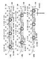
図2は、好ましい実施形態におけるステータ部30を示す平面図である。
ステータ部30は、9つのティース部34を有する。コイル31は、9つのティース部34に3つずつ巻かれた3つのコイル群により構成される。3つのコイル群は、それぞれU相群、V相群、W相群である。U相群を構成するコイル31は、以下、コイル31Uと記す。V相群を構成するコイル31は、以下、コイル31Vと記す。W相群を構成するコイル31は、以下、コイル31Wと記す。
FIG. 2 is a plan view showing the
The
3つのコイル群は、それぞれ1本の巻線60が複数のコイル31となる。巻線60は、絶縁被膜を有するエナメル線である。巻線60は、渡り線61と、引出線62と、を含む。巻線60は、ティース部34に対し巻かれる。巻線60がティース部34に対し軸方向に多層状に構成されることで、コイル31となる。巻線60は、ティース部34の径方向内端部34aから巻き始められる。巻線60は、ティース部34の径方向内端部34aから径方向外側に向かって巻かれた後、再び径方向内端部34aに向かって巻かれる。巻線60は、ティース部34の径方向内端部34a近傍において巻き終わる。したがって、巻線60は、好ましくはティース部34に対し偶数層に巻かれ、例えば4層である。引出線62は、コアバック33の内側面33aよりも径方向外側に位置する。引出線62は、コイル31から引き出され、後述の図3に示すように、ティース部34の上面34A側から下面34B側に引き出される。また、引出線62は、ティース部34の径方向内端部34aにおいて、ティース部34の上面34A側から下面34B側へ引き出される。
In each of the three coil groups, one winding 60 is a plurality of
コイル31を構成する巻線60のうち、コイル31Uを構成する巻線60は、以下、巻線60Uと記す。コイル31Vを構成する巻線60は、以下、巻線60Vと記す。コイル31Wを構成する巻線60は、以下、巻線60Wと記す。巻線60Uの一方の端部は、引出線62Uとして引き出される。また、巻線60Vの一方の端部は、引出線62Vとして引き出される。また、巻線60Wの一方の端部は、引出線62Wとして引き出される。
Hereinafter, the winding 60 constituting the
巻線60U,60V,60Wの他方の端部は、1本に寄り合わされてコモン線として引き出される。以下、コモン線は、引出線62Cとして記す。このように、4本の引出線62が、ステータコア32から引き出される。4本の引出線62は、それぞれ異なるスロットから引き出される。隣り合うティース部34の間には、スロットS1〜S9がある。引出線62Uは、スロットS1から引き出される。引出線62Vは、スロットS2から引き出される。引出線62Wは、スロットS3から引き出される。引出線62Cは、スロットS9から引き出される。
The other ends of the
図3は、好ましい実施形態における巻線60の巻きパターンを示す図である。図3は、環状のステータコア32を直線状に展開した図である。また、以下の説明においては、図3に示すティース部34に番号を付して説明する。図3に示すように、1番目から9番目のティース部34に、符号T1から符号T9を付す。
図3に示すように、巻線60Uは、1番目のティース部34と、4番目のティース部34と、7番目のティース部34と、に巻かれる。
FIG. 3 is a diagram showing a winding pattern of the winding 60 in a preferred embodiment. FIG. 3 is a diagram in which the
As shown in FIG. 3, the winding
コイル31同士を接続する渡り線61は、第1線部63と、第2線部64と、を有する。第1線部63は、隣り合うティース部34の上面34A側のみを通る。第2線部64は、隣り合うティース部34の上面34A側と下面34B側とに亘って延び、且つティース部34の下面側を通る。巻線60Uは、1番目のティース部34のコイル31Uと、4番目のティース部34のコイル31Uと、を接続する渡り線61Uを有する。渡り線61Uの第2線部64Uは、1番目のティース部34の上面34A側から始まる。
The
第2線部64Uは、スロットS2を通る。スロットS2を通った第2線部64Uは、2番目のティース部34の下面34B側を通る。2番目のティース部34の下面34B側を通った第2線部64Uは、スロットS3を通る。スロットS3を通った第2線部64Uは、3番目のティース部34の上面34A側に至る。渡り線61Uの第1線部63Uは、3番目のティース部34の上面34A側から始まる。第1線部63Uは、3番目のティース部34の上面34A側から、4番目のティース部34の上面34A側に至る。
The
また、巻線60Uは、4番目のティース部34のコイル31Uと、7番目のティース部34のコイル31Uと、を接続するもう一つの渡り線61Uを有する。もう一つの渡り線61Uの第2線部64Uは、4番目のティース部34の上面34A側から始まる。第2線部64Uは、スロットS5を通る。スロットS5を通った第2線部64Uは、5番目のティース部34の下面34B側を通る。5番目のティース部34の下面34B側を通った第2線部64Uは、スロットS6を通る。スロットS6を通った第2線部64Uは、6番目のティース部34の上面34A側に至る。
Further, the winding 60U has another
渡り線61Uの第1線部63Uは、6番目のティース部34の上面34A側から始まる。第1線部63Uは、6番目のティース部34の上面34A側から、7番目のティース部34の上面34A側に至る。引出線62Cを構成する巻線60Uの他方の端部は、7番目のティース部34の上面34A側から下面34B側に引き出される。引出線62Cを構成する巻線60Uの他方の端部は、以下、巻線60Uの引出線62Cと記す。引出線62Cは、スロットS8を通る。
The
スロットS8を通った引出線62Cは、8番目のティース部34の下面34B側を通る。8番目のティース部34の下面34B側を通った引出線62Cは、スロットS9の下方で、1本のコモン線として寄り合わされる。一方、引出線62Uを構成する巻線60Uの一方の端部は、1番目のティース部34の上面34A側から下面34B側に引き出される。引出線62Uは、スロットS1を通る。
The
巻線60Vの巻きパターンは、巻線60Uの巻きパターンと略同じである。図3に示すように、巻線60Vは、1番目のティース部34のコイル31Uのとなりである、2番目のティース部34に巻かれる。巻線60Vは、2番目のティース部34のコイル31Vと5番目のティース部34のコイル31Vとの間、および5番目のティース部34のコイル31Vと8番目のティース部34のコイル31Vとの間に、渡り線61Vを有する。
The winding pattern of the winding 60V is substantially the same as the winding pattern of the winding 60U. As shown in FIG. 3, the winding
引出線62Cを構成する巻線60Vの他方の端部は、8番目のティース部34の上面34A側から下面34B側に引き出される。引出線62Cを構成する巻線60Vの他方の端部は、以下、巻線60Vの引出線62Cと記す。引出線62Cは、スロットS9を通る。スロットS9を通った引出線62Cは、スロットS9の下方で、1本のコモン線として寄り合わされる。一方、引出線62Vを構成する巻線60Vの一方の端部は、2番目のティース部34の上面34A側から下面34B側に引き出される。引出線62Vは、スロットS2を通る。その他の構成は、巻線60Uの巻きパターンと同じである。
The other end of the winding 60V constituting the
また、巻線60Wの巻きパターンは、巻線60U,60Vの巻きパターンと略同じである。図3に示すように、巻線60Wは、2番目のティース部34のコイル31Vのとなりである、3番目のティース部34に巻かれる。巻線60Wは、3番目のティース部34のコイル31Wと6番目のティース部34のコイル31Wとの間、および6番目のティース部34のコイル31Wと9番目のティース部34のコイル31Wとの間に、渡り線61Wを有する。
The winding pattern of the winding 60W is substantially the same as the winding pattern of the
引出線62Cを構成する巻線60Wの他方の端部は、9番目のティース部34の上面34A側から下面34B側に引き出される。引出線62Cを構成する巻線60Wの他方の端部は、以下、巻線60Wの引出線62Cと記す。引出線62Cは、スロットS1を通る。スロットS1を通った引出線62Cは、9番目のティース部34の下面34B側を通る。9番目のティース部34の下面34B側を通った引出線62Cは、スロットS9の下方で、1本のコモン線として寄り合わされる。一方、引出線62Wを構成する巻線60Wの一方の端部は、3番目のティース部34の上面34A側から下面34B側に引き出される。引出線62Wは、スロットS3を通る。その他の構成は、巻線60U、60Vの巻きパターンと同じである。
The other end of the winding
図2に示すように、渡り線61は、コアバック33の内側面33aよりも径方向外側に位置する。渡り線61の第2線部64は、隣り合うティース部34の上面34A側から下面34B側へと延び、また別の隣り合うティース部34の下面34B側から上面34A側へと延びる。そのため、第2線部64は、コアバック33の外側面33bよりも径方向外側に位置する。一方、渡り線61の第1線部63の少なくとも一部は、コアバック33の外側面33bよりも径方向外側に位置する。第1線部63の残りの部分は、コアバック33の上面33cに位置する。
As shown in FIG. 2, the
第1線部63は、隣り合うティース部34の上面34A側のみを通るため、第2線部64のようにティース部34の下面34B側を通ることは無い。例えば、第1線部63Uが、6番目のティース部34から7番目のティース部34に延びると、コアバック33の内側面33aに近づく。好ましい実施形態では、第1線部63は、コアバック33の外側面33bよりも径方向外側に配置される角部65を有する。角部65は、鈍角で屈曲する。角部65は、スロットに位置する。
Since the
角部65によって、第1線部63の一部が、コアバック33の外側面33bよりも径方向外側に位置する。よって、第1線部63がコアバック33の内側面33aよりも径方向外側に配置される。第1線部63とコアバック33の外側面33bとの間には、巻線60を巻く際、スロットに位置する部位には、不図示の巻き冶具が配置される。巻き冶具は、好ましくは軸方向に延びる棒状である。6番目のティース部34を通った第1線部63は、巻き治具の外表面に接触しながら、7番目のティース部34へ延びる。そして7番目のティース部34に達した巻線60は、7番目のティース部34に巻かれる。巻線60が巻き終わり、巻き冶具を軸方向に抜くと、角部65を有する第1線部63が形成される。
The
静止部2は、図2に示すように、固定部材70を有する。固定部材70は、少なくともコアバック33の上面33cに位置する。固定部材70は、渡り線61の少なくとも一部、および引出線62の少なくとも一部をステータコア32に固定する。固定部材70は、コアバック33の上面33cの略全域に配置される。なお、固定部材70は、コアバック33の内側面33aから所定の距離をあけて配置してもよい。例えば、固定部材70は、コアバック33の上面33cの径方向外側半分の領域に配置してもよい。
The
図4は、好ましい実施形態における固定部材70を示す縦断面図である。図4は、図2の矢視A−A断面である。
固定部材70は、好ましくは樹脂材料である。固定部材70は、例えば熱硬化型の接着剤である。固定部材70は、コアバック33の上面33cからコアバック33の外側面33bまで達する。コアバック33の上面33cに位置する固定部材70の高さは、コイル31の上端部31aの高さよりも低い。図1に示すように、回転部10の高さを低くできる。よって、スピンドルモータ1の装置全体を小型化できる。なお、接着剤は、熱硬化型の接着剤に限らず、例えば紫外線硬化型の接着剤でもよい。
FIG. 4 is a longitudinal sectional view showing the fixing
The fixing
固定部材70は、図4に示すように、コイル31の径方向内端部31bをステータコア32に固定する。固定部材70は、ティース部34、およびコイル31の径方向内端部31bに密着する。図2に示すように、例えば、1番目のティース部34に巻かれたコイル31Uの径方向内端部31bは、引出線62Uに連なる。引出線62Uは、コイル31Uの径方向内端部31bを介してステータコア32に固定される。よって、引出線62Uのゆるみを抑制できる。
引出線がゆるむと、引出線がコイルより上方に位置してしまい、引出線が回転部に接触してしまう虞がある。しかし、引出線62Uのゆるみを抑制することで、引出線62Uが回転部10に接触することを防止できる。したがって、引出線62Uの損傷および断線を防止できる。なお、他の引出線62V,62W,62Cにおいても同様にゆるみを抑制できる。
As shown in FIG. 4, the fixing
When the lead wire is loosened, the lead wire may be positioned above the coil, and the lead wire may come into contact with the rotating portion. However, by suppressing the loosening of the
また、固定部材70は、図4に示すように、第1線部63の少なくとも一部をステータコア32に固定する。固定部材70は、コアバック33の上面33cに位置する第1線部63を固定する。すなわち、固定部材70は、コアバック33の上面33c、および第1線部63に密着する。よって、第1線部63がコアバック33の上面33cの内側へ移動することを抑制できる。したがって、第1線部63の移動によって、ステータコア32を円筒部41に圧入する際、圧入用治具に第1線部63が接触する噛み込みを抑制できる。また、固定部材70は、コアバック33の外側面33bよりも径方向外側に位置する第1線部63を固定する。
Further, as shown in FIG. 4, the fixing
図5は、好ましい実施形態における固定部材70を示す平面拡大図である。
図5に示すように、第1線部63の少なくとも一部は、コアバック33の外側面33bよりも径方向外側に位置する。固定部材70は、コアバック33の外側面33bと、外側面33bよりも径方向外側に位置する第1線部63と、の隙間72の少なくとも一部に介在する。固定部材70は、樹脂材料であり、隙間72に薄い膜73が介在する。固定部材70の膜73は、コアバック33の外側面33bと第1線部63と隣接部分に介在する。第1線部63の角部65によって、第1線部63がコアバック33の外側面33bから徐々に径方向外側に延びるため、固定部材70は表面張力により隙間72に保持され易い。
FIG. 5 is an enlarged plan view showing the fixing
As shown in FIG. 5, at least a portion of the
固定部材70は、図4に示すように、コアバック33の上面33c、コアバック33の外側面33b、および第1線部63と密着する。よって、コアバック33の外側面33bよりも径方向外側に配置される第1線部63が径方向内側へ移動することを抑制できる。また、第2線部64よりも移動し易い第1線部63は、図2に示すように、上側(+Z側)に位置する。このため、少なくともコアバック33の上面33cに位置する固定部材70によって、第1線部63を一括で固定できる。また、固定部材70を設ける範囲を限定できる。例えば、固定部材70は、図4に示すように、コアバック33の内側面33a、およびコアバック33の下面33dには配置する必要がない。よって、作業性が高まる。
The fixing
以上のように、固定部材70は、渡り線61の少なくとも一部、および引出線62の少なくとも一部をステータコア32に固定する。このため、コイル31の引出線62および渡り線61が移動することを抑制できる。具体的には、渡り線61が、コアバック33の上面33cの内側へ移動することを抑制できる。したがって、渡り線61の移動によって、ステータコア32を円筒部41に圧入する際、圧入用治具に渡り線61が接触する噛み込みを抑制できる。また、引出線62のゆるみを抑制できる。したがって、引出線62が回転部10に接触することを防止できる。そして、引出線62の損傷および断線を防止できる。また、固定部材70がステータコア32の上側に位置するため、ステータコア32の圧入方向後方側に、渡り線61および引出線62を固定できる。また、引出線62をベース部貫通孔42に配置した際などに、引出線62を下側から上側に押し上げても、固定部材70により引出線62のゆるみを抑制できる。
As described above, the fixing
なお、好ましい実施形態においては、以下の構成を採用することもできる。以下の説明において、上述の好ましい実施形態と同一又は同等の構成については同一の符号を付し、その説明を簡略または省略する。 In the preferred embodiment, the following configuration can also be adopted. In the following description, the same or equivalent components as or to those of the preferred embodiment described above are designated by the same reference numerals, any explanation of which will be simplified or omitted.
図6は、好ましい実施形態の一変形例における固定部材70Aを示す縦断面図である。
固定部材70Aは、図6に示すように、シート状部品を含む。シート状部品は、好ましくは環状である。シート状部品は、熱可塑性樹脂材料である。シート状部品を加熱すると、シート状部品が軟化し、コアバック33の上面33c、および渡り線61に沿って変形する。シート状部品が変形することで、シート状部品は、コアバック33の上面33c、および渡り線61に密着する。シート状部品によって、渡り線61の第1線部63が内側へ移動することを抑制できる。また、第1線部63の移動による渡り線61の噛み込みを抑制できる。また、シート状部品によって、図示しない引出線62が、渡り線61と共に固定される。引出線62が固定されることによって、引出線62のゆるみを抑制できる。したがって、引出線62が回転部10に接触することを防止できる。そして、引出線62の損傷および断線を防止できる。
なお、渡り線61はシート状部品によって固定され、図示しない引出線62は、接着剤で固定されてもよい。また、シート状部品は、環状に限らず、様々な形状が可能である。また、シート状部品は、1個に限らず、複数個でも良い。
FIG. 6 is a longitudinal sectional view showing a fixing
The fixing
In addition, the
図7は、好ましい実施形態の一変形例における巻線60Aの巻きパターンを示す図である。
巻線60Aの巻きパターンでは、図7に示すように、巻線60Uは、3番目のティース部34から巻き始められる。巻線60Uは、9番目のティース部34で巻き終わる。引出線62Cは、スロットS1を通る。スロットS1を通った引出線62Cは、9番目のティース部34の下面34B側から、8番目のティース部34の下面34B側に戻る。8番目のティース部34の下面34B側に戻った引出線62Cは、スロットS8を通る。スロットS8を通った引出線62Cは、8番目のティース部34の上面34A側を通る。8番目のティース部34の上面34A側を通った引出線62Cは、スロットS9を通る。スロットS9を通った引出線62Cは、スロットS9の下方で、1本のコモン線として寄り合わされる。
FIG. 7 is a view showing a winding pattern of the winding 60A in a modification of the preferred embodiment.
In the winding pattern of the winding 60A, as shown in FIG. 7, the winding 60U starts winding from the
また、巻線60Vは、2番目のティース部34から巻き始められる。巻線60Vは、8番目のティース部34で巻き終わる。引出線62Cは、スロットS9を通る。スロットS9を通った引出線62Cは、スロットS9の下方で、1本のコモン線として寄り合わされる。
また、巻線60Wは、1番目のティース部34から巻き始められる。巻線60Wは、7番目のティース部34で巻き終わる。引出線62Cは、7番目のティース部34の上面34A側から、8番目のティース部34の上面34A側に至る。引出線62Cは、スロットS9を通る。スロットS9を通った引出線62Cは、スロットS9の下方で、1本のコモン線として寄り合わされる。
巻線60Aの巻きパターンによれば、巻線60U,60V,60Wの引出線62Cを、スロットS9を通して寄り合わせることができる。
In addition, the winding 60V is started to be wound from the
In addition, the winding 60W is started to be wound from the
According to the winding pattern of the winding 60A, the
図8は、好ましい他の実施形態におけるスピンドルモータ1Aを示す縦断面図である。
スピンドルモータ1Aの静止部2は、図8に示すように、外側面41bと、ベース部40と、シャフト21Bと、有する。シャフト21Bは、ベース部40に固定されている。シャフト21Bは、軸方向に延びる。シャフト21Bは、ベース部40に固定されるネジ部81と、ネジ部81の上側に位置するスラストプレート82と、ネジ部81とスラストプレート82との間に位置するステータコア支持部83と、を有する。シャフト21Bと、スリーブ22B1,22B2は、軸受部20Bを構成する。
FIG. 8 is a longitudinal sectional view showing a
The
スリーブ22B1は、ステータコア支持部83よりも上側に位置する。スリーブ22B1は、ロータハブ12に嵌め込まれる。また、スリーブ22B1には、スラストプレート82の上面と対向するスラストブッシュ23が固定される。一方、スリーブ22B2は、ステータコア支持部83よりも下側に位置する。スリーブ22B2は、接着剤84によってロータハブ12に固定されている。
The sleeve 22B1 is located above the stator
シャフト21Bとスリーブ22B1,22B2とは、隙間を介し対向する。隙間には、潤滑油または気体が介在する。また、ロータハブ12とロータマグネット13の間に、磁路となるヨーク14を有する。シャフト21Bは、軸方向に延びると共に、外側面41bを有する。コアバック33の内側面33aは、シャフト21Bの外側面41bに圧入される。
The
固定部材70は、接着剤、シート状部品に限らず、例えば、キャップ状部品を含む構成であってもよい。
The fixing
なお、上記説明した各構成は、相互に矛盾しない範囲内において、適宜組み合わせることができる。 In addition, each structure demonstrated above can be combined suitably in the range which does not contradiction mutually.
1,1A…スピンドルモータ、2…静止部、10…回転部、21B…シャフト、30…ステータ部、31…コイル、31b…径方向内端部、32…ステータコア、33…コアバック、33a…内側面、33b…外側面、33c…上面、34…ティース部、34a…径方向内端部、41…円筒部、41b…外側面、60,60A…巻線、61…渡り線、62…引出線、63…第1線部、64…第2線部、65…角部、70,70A…固定部材、72…隙間、100…ディスク駆動装置、101…ディスク、102…アクセス部、J…中心軸
1, 1A: spindle motor, 2: stationary part, 10: rotating part, 21B: shaft, 30: stator part, 31: coil, 31b: radial inner end, 32: stator core, 33: core back, 33a: inside
Claims (9)
前記静止部に対し上下に延びる中心軸を中心に回転する回転部と、を備え、
前記静止部は、
環状のコアバックと前記コアバックから径方向外側に延びる複数のティース部とを有するステータコア、および前記複数のティース部に巻かれたコイルを有するステータ部と、
前記コアバックの内側面に圧入される外側面と、を有し、
前記コイルを構成する巻線は、
前記コイル同士を接続する渡り線と、 前記コイルから引き出され、前記ティース部の上面側から下面側に引き出される引出線と、を含み、
前記渡り線は、隣り合う前記ティース部の上面側のみを通る第1線部を有し、
前記渡り線および前記引出線は、前記コアバックの内側面よりも径方向外側に位置し、
少なくとも前記コアバックの上面に位置する固定部材を有し、
前記固定部材は、樹脂材料であり、前記渡り線の少なくとも一部、および前記引出線の少なくとも一部を前記ステータコアに固定し、
前記第1線部の少なくとも一部は、前記コアバックの外側面よりも径方向外側に位置し、
前記固定部材は、前記コアバックの外側面と前記第1線部との隙間の少なくとも一部に介在する、
スピンドルモータ。 Stationary part,
And a rotating unit that rotates about a central axis extending vertically with respect to the stationary unit,
The stationary unit is
A stator core having an annular core back and a plurality of teeth extending radially outward from the core back; and a stator having a coil wound around the plurality of teeth.
And an outer surface pressed into the inner surface of the core back,
The windings constituting the coil are:
The crossover connecting the coils to each other; and a lead wire drawn from the coil and drawn from the upper surface side to the lower surface side of the tooth portion,
The crossover has a first line portion passing only on the upper surface side of the adjacent teeth portions,
The crossover wire and the lead wire are located radially outward of the inner surface of the core back,
It has a fixing member located on the upper surface of at least the core back,
The fixing member is a resin material, to secure at least a portion of the crossover wire, and at least a portion of said lead wire to said stator core,
At least a portion of the first wire portion is located radially outward of the outer surface of the core back,
The fixing member is interposed in at least a part of a gap between the outer surface of the core back and the first wire portion.
Spindle motor.
前記固定部材は、前記コイルの径方向内端部を前記ステータコアに固定する、
請求項1に記載のスピンドルモータ。 The lead wire is drawn from the upper surface side to the lower surface side at a radially inner end portion of the tooth portion,
The fixing member fixes a radially inner end of the coil to the stator core.
The spindle motor according to claim 1.
前記固定部材は、前記第1線部の少なくとも一部を前記ステータコアに固定する、
請求項1または2に記載のスピンドルモータ。 The connecting wire has a second line portion through extending across the upper surface of the neighboring Ri fit the tooth portion and the lower surface side and lower surface side of the tooth portion,
The fixing member fixes at least a part of the first wire portion to the stator core.
The spindle motor according to claim 1.
前記コアバックの上面に位置する前記固定部材の高さは、前記コイルの上端部の高さよりも低い、
請求項3に記載のスピンドルモータ。 Before SL securing member extends from an upper surface of the core back to the outer surface of the core back,
The height of the fixing member located on the upper surface of the core back is lower than the height of the upper end of the coil,
The spindle motor according to claim 3.
請求項1に記載のスピンドルモータ。 The spindle motor according to claim 1.
前記シート状部品は、前記コアバックの上面、および前記渡り線に密着する、 The sheet-like component is in close contact with the upper surface of the core back and the crossover.
請求項1から3のいずれか一項に記載のスピンドルモータ。 The spindle motor according to any one of claims 1 to 3.
前記円筒部は、前記外側面を有する、 The cylindrical portion has the outer side,
請求項1から6のいずれか一項に記載のスピンドルモータ。 The spindle motor according to any one of claims 1 to 6.
前記シャフトは、前記中心軸の軸方向に延びると共に、前記外側面を有する、 The shaft extends in the axial direction of the central axis and has the outer surface.
請求項1から6のいずれか一項に記載のスピンドルモータ。 The spindle motor according to any one of claims 1 to 6.
前記スピンドルモータに支持されたディスクと、 A disk supported by the spindle motor;
前記ディスクに対して情報の読み出し、および書き込みの少なくともいずれか一方を行うアクセス部と、を備える、 An access unit that reads and / or writes information to the disk;
ディスク駆動装置。 Disk drive.
Priority Applications (3)
| Application Number | Priority Date | Filing Date | Title |
|---|---|---|---|
| JP2014266518A JP6515533B2 (en) | 2014-12-26 | 2014-12-26 | Spindle motor and disk drive |
| US14/835,932 US9369019B1 (en) | 2014-12-26 | 2015-08-26 | Spindle motor and disk drive apparatus |
| CN201510686367.8A CN105743256B (en) | 2014-12-26 | 2015-10-21 | Spindle motor and disk drive device |
Applications Claiming Priority (1)
| Application Number | Priority Date | Filing Date | Title |
|---|---|---|---|
| JP2014266518A JP6515533B2 (en) | 2014-12-26 | 2014-12-26 | Spindle motor and disk drive |
Publications (2)
| Publication Number | Publication Date |
|---|---|
| JP2016127699A JP2016127699A (en) | 2016-07-11 |
| JP6515533B2 true JP6515533B2 (en) | 2019-05-22 |
Family
ID=56100667
Family Applications (1)
| Application Number | Title | Priority Date | Filing Date |
|---|---|---|---|
| JP2014266518A Expired - Fee Related JP6515533B2 (en) | 2014-12-26 | 2014-12-26 | Spindle motor and disk drive |
Country Status (3)
| Country | Link |
|---|---|
| US (1) | US9369019B1 (en) |
| JP (1) | JP6515533B2 (en) |
| CN (1) | CN105743256B (en) |
Families Citing this family (8)
| Publication number | Priority date | Publication date | Assignee | Title |
|---|---|---|---|---|
| JP2017522852A (en) * | 2014-08-01 | 2017-08-10 | ピアッジオ・アンド・シー.・エス.ピー.エー.Piaggio & C. S.P.A. | Permanent magnet electric motor / generator and hybrid motor with scooter equipped with permanent magnet electric motor / generator |
| CN107925299B (en) * | 2015-09-28 | 2019-12-10 | 日本电产株式会社 | stator, motor, disk drive device, and method for manufacturing stator |
| JP6774600B2 (en) * | 2016-12-16 | 2020-10-28 | 日本電産株式会社 | Motor and disk drive |
| JPWO2018143449A1 (en) * | 2017-02-06 | 2019-11-21 | 日本電産サーボ株式会社 | motor |
| WO2020195580A1 (en) * | 2019-03-25 | 2020-10-01 | デンソートリム株式会社 | Rotating electric machine and stator thereof |
| JP2021010214A (en) * | 2019-06-28 | 2021-01-28 | 日本電産株式会社 | motor |
| DE102019122329A1 (en) * | 2019-08-20 | 2021-02-25 | Minebea Mitsumi Inc. | Stator for an electric machine |
| DE102020120235A1 (en) | 2020-07-31 | 2022-02-03 | Minebea Mitsumi Inc. | Stator for a DC motor |
Family Cites Families (14)
| Publication number | Priority date | Publication date | Assignee | Title |
|---|---|---|---|---|
| JPS5828457Y2 (en) * | 1978-09-18 | 1983-06-21 | 松下電器産業株式会社 | rotating electric machine |
| JP2881528B2 (en) | 1992-05-15 | 1999-04-12 | ミネベア株式会社 | Flat motor stator structure |
| JPH0759317A (en) | 1993-08-18 | 1995-03-03 | Shibaura Eng Works Co Ltd | Motor |
| JPH0759316A (en) | 1993-08-18 | 1995-03-03 | Shibaura Eng Works Co Ltd | Motor |
| CN1178609A (en) * | 1995-11-20 | 1998-04-08 | 昆腾公司 | D. C. brushless motor with minimized net radial forces and low cogging torque |
| JP2001069717A (en) | 1999-08-31 | 2001-03-16 | Seiko Instruments Inc | Electric motor |
| JP2002101606A (en) | 2000-09-20 | 2002-04-05 | Fujitsu General Ltd | Electric motor |
| JP2003324886A (en) * | 2002-04-30 | 2003-11-14 | Sankyo Seiki Mfg Co Ltd | Motor and manufacturing method therefor |
| JP2005110462A (en) | 2003-10-02 | 2005-04-21 | Matsushita Electric Ind Co Ltd | Small-sized motor and manufacturing method therefor |
| JP4848497B2 (en) * | 2005-11-18 | 2011-12-28 | 多摩川精機株式会社 | Stator structure for outer rotor resolver |
| JP5513070B2 (en) | 2009-10-22 | 2014-06-04 | サムスン電機ジャパンアドバンスドテクノロジー株式会社 | Disk drive |
| KR101240696B1 (en) | 2011-02-08 | 2013-03-11 | 삼성전기주식회사 | Stator core assembled body and motor including the same |
| JP2013118718A (en) * | 2011-12-01 | 2013-06-13 | Nippon Densan Corp | Method of manufacturing motor, motor, and disk drive apparatus |
| JP6241081B2 (en) * | 2013-06-07 | 2017-12-06 | 日本電産株式会社 | Spindle motor for disk drive, disk drive and stator manufacturing method |
-
2014
- 2014-12-26 JP JP2014266518A patent/JP6515533B2/en not_active Expired - Fee Related
-
2015
- 2015-08-26 US US14/835,932 patent/US9369019B1/en not_active Expired - Fee Related
- 2015-10-21 CN CN201510686367.8A patent/CN105743256B/en not_active Expired - Fee Related
Also Published As
| Publication number | Publication date |
|---|---|
| JP2016127699A (en) | 2016-07-11 |
| US20160190885A1 (en) | 2016-06-30 |
| US9369019B1 (en) | 2016-06-14 |
| CN105743256B (en) | 2018-09-04 |
| CN105743256A (en) | 2016-07-06 |
Similar Documents
| Publication | Publication Date | Title |
|---|---|---|
| JP6515533B2 (en) | Spindle motor and disk drive | |
| US9837872B2 (en) | Motor and disk drive apparatus | |
| US9935528B2 (en) | Spindle motor and disk drive apparatus | |
| US8749915B2 (en) | Motor unit including circuit board arranged on a base portion and disk drive apparatus | |
| US8400729B1 (en) | Method of manufacturing motor, motor, and disk drive apparatus | |
| US7633204B2 (en) | Motor stator, spindle motor including the motor stator, and disk drive including the spindle motor | |
| US8754554B2 (en) | Motor and disk drive apparatus | |
| US9064530B1 (en) | Motor and disk drive apparatus | |
| US8599517B1 (en) | Spindle motor and disk drive apparatus | |
| JP6241081B2 (en) | Spindle motor for disk drive, disk drive and stator manufacturing method | |
| JP6569240B2 (en) | Spindle motor and disk drive device | |
| US9837113B2 (en) | Spindle motor and disk drive apparatus | |
| US20160267937A1 (en) | Spindle motor and disk drive apparatus | |
| US8737017B1 (en) | Spindle motor and disk drive apparatus | |
| JP2006296079A (en) | Slim spindle motor | |
| JP2012050298A (en) | Spindle motor and disc driving device | |
| JP2009247103A (en) | Spindle motor and disc drive device | |
| JP5522585B2 (en) | motor | |
| KR101240696B1 (en) | Stator core assembled body and motor including the same | |
| US20130050871A1 (en) | Spindle motor and disk drive apparatus | |
| US8941946B2 (en) | Motor including dynamic bearing with seal portion and disk drive apparatus including the same | |
| CN101097754A (en) | Disk apparatus | |
| JP6812982B2 (en) | Stator, motor, disk drive | |
| US8867165B2 (en) | Spindle motor and disk drive apparatus | |
| JP5300043B2 (en) | STATOR, MOTOR, AND RECORDING MEDIUM DRIVE DEVICE |
Legal Events
| Date | Code | Title | Description |
|---|---|---|---|
| A621 | Written request for application examination |
Free format text: JAPANESE INTERMEDIATE CODE: A621 Effective date: 20171121 |
|
| A131 | Notification of reasons for refusal |
Free format text: JAPANESE INTERMEDIATE CODE: A131 Effective date: 20180918 |
|
| A977 | Report on retrieval |
Free format text: JAPANESE INTERMEDIATE CODE: A971007 Effective date: 20180913 |
|
| A521 | Request for written amendment filed |
Free format text: JAPANESE INTERMEDIATE CODE: A523 Effective date: 20181030 |
|
| TRDD | Decision of grant or rejection written | ||
| A01 | Written decision to grant a patent or to grant a registration (utility model) |
Free format text: JAPANESE INTERMEDIATE CODE: A01 Effective date: 20190319 |
|
| A61 | First payment of annual fees (during grant procedure) |
Free format text: JAPANESE INTERMEDIATE CODE: A61 Effective date: 20190401 |
|
| R151 | Written notification of patent or utility model registration |
Ref document number: 6515533 Country of ref document: JP Free format text: JAPANESE INTERMEDIATE CODE: R151 |
|
| LAPS | Cancellation because of no payment of annual fees |