JP5504356B2 - Recliner system for vehicle seat - Google Patents
Recliner system for vehicle seat Download PDFInfo
- Publication number
- JP5504356B2 JP5504356B2 JP2012552319A JP2012552319A JP5504356B2 JP 5504356 B2 JP5504356 B2 JP 5504356B2 JP 2012552319 A JP2012552319 A JP 2012552319A JP 2012552319 A JP2012552319 A JP 2012552319A JP 5504356 B2 JP5504356 B2 JP 5504356B2
- Authority
- JP
- Japan
- Prior art keywords
- recliner
- stopper
- stopper module
- hand lever
- module
- Prior art date
- Legal status (The legal status is an assumption and is not a legal conclusion. Google has not performed a legal analysis and makes no representation as to the accuracy of the status listed.)
- Active
Links
- 230000005540 biological transmission Effects 0.000 claims description 54
- 238000003466 welding Methods 0.000 claims description 12
- 230000014759 maintenance of location Effects 0.000 claims description 5
- 238000000034 method Methods 0.000 claims description 3
- 230000002093 peripheral effect Effects 0.000 claims description 3
- 238000001746 injection moulding Methods 0.000 claims description 2
- 210000001331 nose Anatomy 0.000 description 15
- 230000008878 coupling Effects 0.000 description 9
- 238000010168 coupling process Methods 0.000 description 9
- 238000005859 coupling reaction Methods 0.000 description 9
- 230000033001 locomotion Effects 0.000 description 8
- 230000004048 modification Effects 0.000 description 6
- 238000012986 modification Methods 0.000 description 6
- 238000013461 design Methods 0.000 description 4
- 230000036316 preload Effects 0.000 description 4
- 230000008030 elimination Effects 0.000 description 3
- 238000003379 elimination reaction Methods 0.000 description 3
- 230000035939 shock Effects 0.000 description 3
- 210000001364 upper extremity Anatomy 0.000 description 3
- 238000004519 manufacturing process Methods 0.000 description 2
- 239000000463 material Substances 0.000 description 2
- 239000002184 metal Substances 0.000 description 2
- 230000000737 periodic effect Effects 0.000 description 2
- 230000002265 prevention Effects 0.000 description 2
- 230000003449 preventive effect Effects 0.000 description 2
- 230000004044 response Effects 0.000 description 2
- 229910000639 Spring steel Inorganic materials 0.000 description 1
- 229910000831 Steel Inorganic materials 0.000 description 1
- 239000011324 bead Substances 0.000 description 1
- 230000008901 benefit Effects 0.000 description 1
- 230000015572 biosynthetic process Effects 0.000 description 1
- 230000008859 change Effects 0.000 description 1
- 238000012217 deletion Methods 0.000 description 1
- 230000037430 deletion Effects 0.000 description 1
- 230000001419 dependent effect Effects 0.000 description 1
- 230000000694 effects Effects 0.000 description 1
- 239000000945 filler Substances 0.000 description 1
- 230000008569 process Effects 0.000 description 1
- 230000000630 rising effect Effects 0.000 description 1
- 239000010959 steel Substances 0.000 description 1
- 230000007704 transition Effects 0.000 description 1
- 238000004804 winding Methods 0.000 description 1
Images


Classifications
-
- B—PERFORMING OPERATIONS; TRANSPORTING
- B60—VEHICLES IN GENERAL
- B60N—SEATS SPECIALLY ADAPTED FOR VEHICLES; VEHICLE PASSENGER ACCOMMODATION NOT OTHERWISE PROVIDED FOR
- B60N2/00—Seats specially adapted for vehicles; Arrangement or mounting of seats in vehicles
- B60N2/02—Seats specially adapted for vehicles; Arrangement or mounting of seats in vehicles the seat or part thereof being movable, e.g. adjustable
- B60N2/22—Seats specially adapted for vehicles; Arrangement or mounting of seats in vehicles the seat or part thereof being movable, e.g. adjustable the back-rest being adjustable
- B60N2/235—Seats specially adapted for vehicles; Arrangement or mounting of seats in vehicles the seat or part thereof being movable, e.g. adjustable the back-rest being adjustable by gear-pawl type mechanisms
- B60N2/2356—Seats specially adapted for vehicles; Arrangement or mounting of seats in vehicles the seat or part thereof being movable, e.g. adjustable the back-rest being adjustable by gear-pawl type mechanisms with internal pawls
- B60N2/236—Seats specially adapted for vehicles; Arrangement or mounting of seats in vehicles the seat or part thereof being movable, e.g. adjustable the back-rest being adjustable by gear-pawl type mechanisms with internal pawls linearly movable
-
- B—PERFORMING OPERATIONS; TRANSPORTING
- B60—VEHICLES IN GENERAL
- B60N—SEATS SPECIALLY ADAPTED FOR VEHICLES; VEHICLE PASSENGER ACCOMMODATION NOT OTHERWISE PROVIDED FOR
- B60N2/00—Seats specially adapted for vehicles; Arrangement or mounting of seats in vehicles
- B60N2/02—Seats specially adapted for vehicles; Arrangement or mounting of seats in vehicles the seat or part thereof being movable, e.g. adjustable
- B60N2/20—Seats specially adapted for vehicles; Arrangement or mounting of seats in vehicles the seat or part thereof being movable, e.g. adjustable the back-rest being tiltable, e.g. to permit easy access
-
- B—PERFORMING OPERATIONS; TRANSPORTING
- B60—VEHICLES IN GENERAL
- B60N—SEATS SPECIALLY ADAPTED FOR VEHICLES; VEHICLE PASSENGER ACCOMMODATION NOT OTHERWISE PROVIDED FOR
- B60N2/00—Seats specially adapted for vehicles; Arrangement or mounting of seats in vehicles
- B60N2/02—Seats specially adapted for vehicles; Arrangement or mounting of seats in vehicles the seat or part thereof being movable, e.g. adjustable
- B60N2/22—Seats specially adapted for vehicles; Arrangement or mounting of seats in vehicles the seat or part thereof being movable, e.g. adjustable the back-rest being adjustable
- B60N2/235—Seats specially adapted for vehicles; Arrangement or mounting of seats in vehicles the seat or part thereof being movable, e.g. adjustable the back-rest being adjustable by gear-pawl type mechanisms
- B60N2/2356—Seats specially adapted for vehicles; Arrangement or mounting of seats in vehicles the seat or part thereof being movable, e.g. adjustable the back-rest being adjustable by gear-pawl type mechanisms with internal pawls
-
- B—PERFORMING OPERATIONS; TRANSPORTING
- B60—VEHICLES IN GENERAL
- B60N—SEATS SPECIALLY ADAPTED FOR VEHICLES; VEHICLE PASSENGER ACCOMMODATION NOT OTHERWISE PROVIDED FOR
- B60N2/00—Seats specially adapted for vehicles; Arrangement or mounting of seats in vehicles
- B60N2/68—Seat frames
- B60N2/682—Joining means
-
- B—PERFORMING OPERATIONS; TRANSPORTING
- B60—VEHICLES IN GENERAL
- B60N—SEATS SPECIALLY ADAPTED FOR VEHICLES; VEHICLE PASSENGER ACCOMMODATION NOT OTHERWISE PROVIDED FOR
- B60N2205/00—General mechanical or structural details
- B60N2205/50—Interlocking shaft arrangements transmitting movement between hinge mechanisms on both sides of a seat
Description
本発明は、請求項1の前提の特徴を有する車両座席用のリクライナシステムに関する。
The present invention relates to a recliner system for a vehicle seat having the features of the premise of
このような種類のリクライナシステムは、独国特許公開公報DE 103 35869 A1により周知である。特別なスプリングがガタツキを除去するためにロッキング方向にて、伝達ロッド上に負荷を課す。さらに、前記スプリングは、軸方向における動きに対抗して前記伝達ロッドを固定する。 A recliner system of this kind is known from German Patent Publication DE 103 35869 A1. A special spring imposes a load on the transmission rod in the locking direction to eliminate rattling. Further, the spring fixes the transmission rod against movement in the axial direction.
冒頭にて説明したタイプのリクライナシステムを改良することが発明の根本的な目的である。本発明によれば、本目的は請求項1の特徴を有するリクライナシステムによって達成される。有利な具現化例は、従属請求項の発明の主題を形成する。
It is a fundamental object of the invention to improve a recliner system of the type described at the outset. According to the invention, this object is achieved by a recliner system having the features of
本発明に係るリクライナシステムは、少なくとも一つのリクライナ、伝達ロッド、ハンドレバー、ストッパモジュール及び、任意として、背もたれ補償スプリングを含む。一方で前記ハンドレバーに、他方で前記伝達ロッドに機能的に結合され、さらに前記ハンドレバー及びリクライナ部の一つを少なくとも一つの回転方向で相互に対して接触を止める状態にする、前記ストッパモジュールは、いくつかの機能を果たす。 The recliner system according to the present invention includes at least one recliner, a transmission rod, a hand lever, a stopper module, and optionally a backrest compensation spring. The stopper module, which is functionally coupled to the hand lever on the one hand and the transmission rod on the other hand, and further stops one of the hand lever and the recliner portion from contacting each other in at least one rotational direction. Fulfills several functions.
前記機能的な結合から得られる第1の機能は、前記ハンドレバーから前記伝達ロッドへのトルクの伝達である。前記機能は、前記ハンドレバーがアンロッキング位置に旋回されると、前記トルクを前記リクライナに伝達する。トルクの伝達は、好ましくは所定の角度範囲に制限され、それゆえ前記ハンドレバーは初期位置と最大偏倚との間のみで旋回される。 The first function obtained from the functional coupling is the transmission of torque from the hand lever to the transmission rod. The function transmits the torque to the recliner when the hand lever is turned to the unlocking position. Torque transmission is preferably limited to a predetermined angular range, so that the hand lever is pivoted only between the initial position and the maximum deflection.
前記第1の機能は、第2の機能のための前提条件であり、前記ハンドレバー及び前記リクライナ部の一つが相互に対して接触を止める状態とされ、さらにトルクがそれにより前記リクライナ部に突き当たり、つまり効果がないということになる、トルク伝達が妨害されるところの、誤使用の予防策である。その結果、前記リクライナの内部部品は、保護される。そのような場合、前記リクライナの前記内部部品は、すでに回転の終端位置を占めており、さらに、前記伝達ロッドによる、さらなる負荷がかかることは、直接的に損傷へと導くので、これは、特にロッキング方向における回転のために、重要である。しかし、誤操作の予防策としての前記停止モジュールの第2の機能は、前記リクライナがアンロックとされ、さらに前記伝達ロッドが前記アンロック方向にさらに回転されると、前記ストッパモジュールが効果的となるように配置することによって拡張される。前記ストッパモジュールは、その後、前記ハンドレバーの作動のための角度範囲を制限する。 The first function is a precondition for the second function, and one of the hand lever and the recliner unit is brought into a state of stopping contact with each other, and further, the torque thereby hits the recliner unit. In other words, it is a preventive measure against misuse where torque transmission is hindered. As a result, the internal parts of the recliner are protected. In such a case, the internal parts of the recliner already occupy the end position of rotation, and further loading by the transmission rod directly leads to damage, which is particularly Important for rotation in the locking direction. However, the second function of the stop module as a preventive measure for erroneous operation is that the stopper module is effective when the recliner is unlocked and the transmission rod is further rotated in the unlocking direction. It is expanded by arranging as follows. The stopper module then limits the angular range for operation of the hand lever.
第3の機能は、ストッパモジュールが、リターンスプリングによってリクライナと接触停止に保持されると、ストッパモジュールとの適切な結合において(前記リターンスプリングの事前に加えられた負荷を下回る)、前記伝達ロッドの相対的な動きを防ぐことによる、ガタツキの排除である。前記リターンスプリングを前記構造内に収容するために、前記ストッパモジュールは、好ましくはカップ状の設計とされる。前記ハンドレバーの端部の定義は、前記ストッパモジュールの第4の機能として言及される。 The third function is that when the stopper module is held in contact with the recliner by the return spring, in proper connection with the stopper module (below the pre-loaded load of the return spring), the transmission rod It is the elimination of rattling by preventing relative movement. In order to accommodate the return spring in the structure, the stopper module is preferably a cup-shaped design. The definition of the end of the hand lever is referred to as the fourth function of the stopper module.
周方向にあって効果的である、第1の機能のため、ねじれ剛性である結合が、前記ハンドレバーと前記ストッパモジュールの間、さらに前記ストッパモジュールと前記伝達ロッド、例えば適切にプロファイルされるレセプタクル、開口、リブ或いは溝の間に好ましくは提供される。同様に周方向にあって効果的である、第2の機能のため、ストッパとカウンタストッパは、周方向における広い停止面を形成するために、半径方向の適切な範囲で軸方向に突出するように好ましくは設計される。カウンタストッパは、関連するリクライナ部に好ましくは形成され、つまり、一体的に、あるいは代替的ではあるが、部分的にも製造され、さらにはリクライナ部に固定されてもよい。 Due to the first function, which is effective in the circumferential direction, a torsionally rigid coupling is provided between the hand lever and the stopper module, as well as the stopper module and the transmission rod, eg a suitably profiled receptacle. , Preferably between the openings, ribs or grooves. Due to the second function, which is also effective in the circumferential direction, the stopper and the counter stopper are projected in the axial direction within a suitable radial range in order to form a wide stop surface in the circumferential direction. Are preferably designed. The counter stopper is preferably formed on the associated recliner part, i.e. it can be manufactured in one piece or alternatively, but also partially, and it can also be fixed to the recliner part.
ラッチングノーズ及びラッチング開口及び/又はクリップフック及びリング或いは環状ビーズは、前記ハンドレバーと前記ストッパモジュールの間、さらには前記ストッパモジュールとリクライナの前記他の部品との間の軸方向のリテンションのために設けられる。適切な結合の様々な要素の間を介してねじれ剛性結合及び軸方向リテンションアレンジメントが設けられる。例えば、押し出しされるセクション仕様においてプロファイルされる、前記ストッパモジュールと伝達ロッドのための適切なオプションは、次の要素を用いるためであり、つまり前記リクライナ内に配置され、前記駆動部に締め付けリング、例えばリクライナに溶接される締め付けリングが好ましい、を設けることによる軸方向のリテンションのため、前記伝達ロッドにより回転される駆動部である。 Latching nose and latching opening and / or clip hook and ring or annular bead for axial retention between the hand lever and the stopper module, and also between the stopper module and the other parts of the recliner Provided. A torsionally rigid connection and an axial retention arrangement are provided between the various elements of the appropriate connection. For example, a suitable option for the stopper module and transmission rod profiled in the section specification to be extruded is to use the following elements, i.e. arranged in the recliner and tightening ring on the drive: For example, a driving part rotated by the transmission rod for axial retention by providing a tightening ring welded to the recliner.
背もたれ補償スプリングは、好ましくはスパイラル設計であり、背もたれの内部端にてサポーティング軸受筒にて補助される。前記サポーティング軸受筒は、リクライナの複数部品の一つに対して端部に好ましくは配置され、後部の軸に整列されて、そこに直接的に溶接される。用語「直接的に溶接される」は、当該リクライナ部と前記サポーティング軸受筒の間にさらなる部品を設けることのないことを意味する。まっすぐな結合は、前記リクライナ部の溶融された材料及びサポーティング軸受筒及び、適宜、溶接の間に付加される充填材料によって達成される。支持のため、前記背もたれ補償スプリングは、前記サポーティング軸受筒上の前記スプリングの最内側の回転によって静止することができ、前記スプリングの端部によってフックされる。前記サポーティング軸受筒は、好ましくは、前記サポーティング軸受筒の円周に沿って遮られる、(環状)リング形状端部を有する。前記サポーティング軸受筒は、好ましくは中空で、両端部が開放されている。リング形状の端部は、前記サポーティング軸受筒と前記リクライナ部の間の環状のジョイントに沿って前記サポーティング軸受筒内でのレーザ溶接を許容する。MAG溶接のため、一端でカップ形状の開口を有する前記サポーティング軸受筒は、前記カップの底部が前記リクライナ部に溶接される場合に、利点を有する。前記ハンドレバーの旋回動きの角度範囲を制限する目的のため、及び前記ストッパモジュールの第2の機能が提供されるところの、カウンタストッパは、前記サポーティング軸受筒上に形成される。 The backrest compensation spring is preferably of a spiral design and is assisted by a supporting bearing barrel at the inner end of the backrest. The supporting cylinder is preferably arranged at the end with respect to one of the recliner parts, aligned with the rear shaft and welded directly thereto. The term “directly welded” means that no further parts are provided between the recliner part and the supporting bearing cylinder. Straight coupling is achieved by the melted material and supporting bearing cylinder of the recliner part and, optionally, filler material added during welding. For support, the back-compensating spring can be rested by the innermost rotation of the spring on the supporting bearing barrel and hooked by the end of the spring. The supporting bearing cylinder preferably has an (annular) ring-shaped end that is interrupted along the circumference of the supporting bearing cylinder. The supporting bearing cylinder is preferably hollow and open at both ends. The ring-shaped end portion allows laser welding in the supporting bearing cylinder along an annular joint between the supporting bearing cylinder and the recliner portion. The supporting bearing cylinder having a cup-shaped opening at one end for MAG welding has an advantage when the bottom of the cup is welded to the recliner. A counter stopper is formed on the supporting bearing cylinder for the purpose of limiting the angular range of the swivel movement of the hand lever and where the second function of the stopper module is provided.
本発明に係るリクライナシステムは、車両座席に用いられ、好ましくは背もたれの傾斜を調整するために用いられるが、他の部分にて用いられることもできる。ディスク形状ユニットとしての前記リクライナの具現化例は、軸周りの相対的な回転を介して前記リクライナ部の間の角度にあって、いかなる所望の変化も実現することを可能とする。前記リクライナ部の軸上の結合は、第1のリクライナ部にわたってフィットし、内側に放射状に曲げられるエッジにより、第1のリクライナ部に相対的に動くことができ、さらには第2のリクライナ部にしっかりと結合されるクラスプリングによって作り出される。 The recliner system according to the present invention is used in a vehicle seat and is preferably used to adjust the inclination of the backrest, but can also be used in other parts. The embodiment of the recliner as a disk-shaped unit is at an angle between the recliner parts through relative rotation about an axis, allowing any desired change to be realized. The on-axis coupling of the recliner part is fitted over the first recliner part and can be moved relative to the first recliner part by an edge that is radially bent inward, and further to the second recliner part. Produced by a clasp spring that is tightly coupled.
本発明は、図に示される二つの具現化例の参照と、変形及び改良により、非常に詳細に説明される。 The invention will be described in greater detail by reference to the two implementations shown in the figures, variations and modifications.
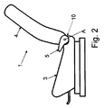
自動車の車両座席1は、座席部3及び背もたれ4を有し、座席部3に対する背もたれ4の傾斜は調節される。背もたれ4の傾斜を調節するため、座席部3と背もたれ部4の間の移行領域にあって水平に配置される伝達ロッド7が、例えば、ハンドレバー5によって手動で回転される。伝達ロッド7は、車両座席1の両側にてリクライナ10に接触する。円筒のコーディネートシステムである、伝達ロッド7は、用いられる方向指示を定義する。
The
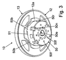
二つのリクライナ部11及び12は、それぞれ概ね実質的ディスク形状と記されることができる。二つのリクライナ部11及び12は、以下に説明される仕様にて製造される。軸方向に作動する力を吸収するため、つまりリクライナ部11及び12を共に保持するため、クラスプリング13が提供される。クラスプリングによってリクライナ部11及び12を保持する方法は、例えば米国6,799,806 B2に、記載されている。好ましくは金属製のクラスプリング13は、二つのリクライナ部11及び12のうちの一つ、例えば第2のリクライナ部12に、好ましくは溶接、或いはクラスプリング13がそこに結合されるリクライナ部とフィットするのであれば、第2のリクライナ部12にフランジ結合される。一方側にて、クラスプリング13は、半径方向内側に曲げられ、さらに二つのリクライナ部11及び12のうちの他の部品、例えば第1のリクライナ部11の半径方向外側にフィットすることによって、選択的に挿入される分離スリップリングが適切であるならば、二つのリクライナ部11及び12の相対的な動きを妨げることのない、端部を有する。製造ということであれば、二つのリクライナ部11及び12は共に(クラスプリング13と)ディスク形状のユニットを形成する。
Each of the two
前記リクライナ10の取り付けの後、第1のリクライナ部11は、背もたれ4の構造体、例えば、本実施例では、背もたれ部4aにしっかりと結合され、つまり、背もたれ4に固定される。第2のリクライナ部12は、その後、座席部3、本具体例では、座席部アダプタ3aにしっかりと結合され、座席部に固定される。しかし、リクライナ部11及び12の関係は交換されることができ、つまり、第1のリクライナ部11は座席部に固定され、第2のリクライナ部12が背もたれに固定されてもよい。
After the
リクライナ10は、戻り止めリクライナとして設計される。第1のリクライナ部11及び第2のリクライナ部12が相互にロックされることができるが、アンロックされると、第1のリクライナ部11及び第2のリクライナ部12は、例えば独国DE 10 2006 015 560 B3に説明されているように、互いに軸A周りに(伝達ロッド7と連携して)相対的に回転される。
The
第2のリクライナ部12は、本具体例の場合には4つのセグメントであるガイドセグメント14の対とされるストレートガイド面14aによって半径方向に横にそれぞれロッキングエレメント16をガイドする。本具体例における合計4つのロッキングエレメント16は、二つのリクライナ部11及び12の間に定義される取り付け空間にあって、それぞれ90°で、相互に相対的にオフセットされるような仕様にて配置される。ロッキングエレメント16は、放射状に外側端部で歯付きセグメントが設けられ、歯付きセグメントは、内部ギアとして設計された第1のリクライナ部11の歯付きリム17にかみ合う(入る)ことができる。歯付きリム17及びロッキングエレメント16が相互に作用すると、リクライナ10がロックされる。ガイドセグメント14はカーブされるベアリング面14bによって第1のリクライナ部11の歯付きリム17に対してそれぞれ静止し、その結果、二つのリクライナ部11及び12は相互に支持する。
In the case of this example, the
代替として、第1のリクライナ部11は、第2のリクライナ部12の窪みに配置され、二つのリクライナ部11及び12が相互に支持して、第2のリクライナ部12は第1のリクライナ部11に外側で放射状にフィットする。この場合、第1のリクライナ部11の外側放射状の端部領域は、ガイドセグメント14と第2のリクライナ部12の外側端部領域(第1のリクライナ部11のために支持を提供するように機能する前記端部領域)の間で歯付きリム17に放射状に配置される。例えば、衝突事故の場合における高負荷の下で、第1のリクライナ部11は、変形の後、第1のリクライナ部11の歯付きリム17によって、負荷の方向に近接するガイドセグメント14のベアリング面14nと噛み合う状態となる。これは、リクライナ10の強度を増加する。
Alternatively, the
リクライナ10の中央に配置されるのは、例えばプラスチックで形成され、二つのリクライナ部11及び12のうちの少なくとも一つ、本具体例では両方のリクライナ部11及び12であり、より詳しくはそれらのリクライナ部の中央部の開口にあって、回転される仕様にて支持される、駆動部21である。車両座席の両側にあって、駆動部21は、ねじれ剛性仕様にて駆動目的のために、中空の駆動部21におけるホール23に導かれる伝達ロッド7に結合されるか、或いは少なくとも連結される。軸方向にあって、駆動部21は、中央部にて、駆動部21の、リクライナ部11及び12にて支持される、二つの端部よりも大きな半径を有するので、二つのリクライナ部11及び12は駆動部21を軸方向に固定する。駆動部21の一端部にて、本具体例の場合、第2のリクライナ部12では、プラスチック製の締め付けリング24が設けられる。締め付けリング24は、超音波溶接によって駆動部21に好ましくは固定される。
Arranged in the center of the
リクライナ部11及び12の間に定義される取り付け空間に配置される偏芯部27は、ねじり剛性仕様にて固定されるか、或いは少なくとも駆動部21上に駆動目的にて結合される。スパイラルスプリングの本具体例にあって、スプリングアレンジメント35は、二つのリクライナ部11及び12のうちの一つの中央レセプタクルに配置されるが、本具体例では、スプリングアレンジメント35は、第2のリクライナ部12の、外側に支持される。内部の駆動部21上のねじれ剛性仕様にて固定されることによって本具体例では、スプリングアレンジメント35には偏芯部27上の負荷が課せられる。内部と外部の入れ子の二つのスパイラルスプリングを有する代替のスプリングアレンジメント35は、独国DE 10 2005 046 807 B3に例えば記載されている。スプリングアレンジメント35によって負荷がかかる偏芯部27は、ロッキングエレメント16を半径方向に移動可能とするように作動し、さらに負荷をそこに課し、その結果、ロッキングエレメント16は、放射状に外側に向かって押され、歯付きリム17を嵌め込み、これによりリクライナ10がロッキングされる。
The
制御ディスク36は、ロッキングエレメント16と第1のリクライナ部11との間の軸上の取り付け空間に配置され、本具体例にあっては、ねじれ剛性仕様にて偏芯部27に取り付けられる。制御ディスク36は、本具体例にあっては、4つのトラックのような制御トラックを有する。各制御トラックは、各ロッキングエレメント16におけるノーズ38と相互に作用する。ノーズ38は、ノーズに関連されるロッキングエレメント16から軸方向に突出する。駆動部21の、それによって駆動される偏芯部27の、スプリングアレンジメント35の力に対向する制御ディスク38の回転(2、3°の)があると、制御ディスク36はロッキングエレメント16を半径方向内側、つまり歯つきリム17の外側に引っ張り、それによってリクライナ10はアンロックされ、二つのリクライナ部11及び12は、軸A周りに相互に対して回転する。これにより、座席の使用のために適合される多くの使用位置の間に、背もたれ4の角度が調整可能となる。
The
2ドアタイプの自動車の場合、アンロックされた背もたれ4が、使用の位置の一つから旋回されて、座席の使用には適さない、背もたれが自由とされる位置まで自由に旋回されるような、背もたれ4の自由な旋回によって後部座席へのアクセスが容易となることが意図される。ハンドレバー5、或いは他の作動要素が自由旋回の全プロセスの間保持されず、さらに前記背もたれが自由旋回される位置にてのみ前記リクライナがロックされるのであれば、操作の利便性は増加する。この目的のため、ねじれ剛性仕様にて第1のリクライナ部11に結合されるリング形状の旋回フリー制御要素45は、リクライナ10にて軸A周りに制御ディスク36と第1のリクライナ部11の間で、任意に旋回される。旋回フリー制御要素45は、ロッキング要素16上で複数ノーズ38と相互に作用するストップトラックを有する。ストップトラックは、ロッキング要素16の半径外側への動きを制限するか、或いはロッキング要素16への噛合を妨害する。背もたれ4が、半径方向外側或いは半径方向内側の異なる距離で、二つのロッキング要素16の間の角度を越えての旋回がフリー(free)とされるのを可能とするため、交互に関連付けられる、ロッキング要素16のノーズ38は、ロッキング要素16に配置され、その結果、近接するノーズ38は異なるストップトラックと相互作用する。ロッキング要素16の異なる設計がここにおいて提供された。詳細は、独国10 2006 015 560 B3に説明されている。
In the case of a two-door type vehicle, the
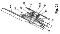
二つのリクライナ10、伝達ロッド7及びハンドレバー5は、リクライナシステムの部品であり、二つのリクライナ10のうちの一つに配置される少なくとも一つの背もたれ補償スプリング47もリクライナシステムに付属する。背もたれ補償スプリング47は、前記二つのリクライナ10のそれぞれに取り付けられることもできる。背もたれ補償スプリング47は、断面がほぼ矩形のスプリングスチールバンドで形成され、スパイラルスプリングとして設計される。
The two
背もたれ補償スプリングの内部端は、対応するリクライナ10上で支持される。このため、リクライナ10は、二つのリクライナ部11又は12のうちの一つに固定されて、軸Aと連携する、サポーティング軸受筒48を有する。サポーティング軸受筒48は、金属製であり、好ましくはスチールである。固定は、好ましくはレーザ溶接によって成される。この目的のため、サポーティング軸受筒48は、関係しているリクライナ部11又は12に対する、リング形状端に配置され、その後、リクライナ部11又は12に溶接される。背もたれ補償スプリング47は、サポーティング軸受筒48の円筒外側上の最内周に静止され、例えば、その端部でサポーティング軸受筒48内のスロットにフックされる。
The inner end of the backrest compensation spring is supported on the corresponding
背もたれ補償スプリング47の外側端は、サポーティング要素49にて支持され、それゆえ、予備負荷(プリロード)の効果によって背もたれ4上に負荷を課す。サポーティング要素49は、例えば、軸方向に突起するピン、軸方向に突起するタブ或いはサポーティングリング状の軸突起物である。この具体例の場合、サポーティング要素49は、サポーティング要素49が軸方向に突出する、背もたれ部4a上に固定される。プリロードは、背もたれ補償リング47が少なくとも部分的に背もたれ4の重量を背もたれ4の使用可能位置にて補償する仕様にて選択される。
The outer end of the
サポーティング軸受筒48がリクライナ10に固定されるところとして、二つの可能性がある。第1の変形は、サポーティング軸受筒48が、本具体例では背もたれに固定される、第1のリクライナ部11に固定されることができるというものである。或いは、改良される第2の変形は、サポーティング軸受筒48が、本具体例では座席部に固定される第2のリクライナ部12に固定されることができるというものである。前記第1の変形にあって、サポーティング軸受筒48が、背もたれに固定される第1のリクライナ部11に固定されるならば、背もたれ補償スプリング47の外側端を支持するのに提供されるピン又はサポーティングリング49などは、状況に応じて、座席部3に例えば溶接により、しっかりと結合される。第2の変形にあって、サポーティング軸受筒48が、座席部に固定される第2のリクライナ部12に固定されるならば、サポーティングリング49或いは背もたれ補償スプリング47の外側端を支持するために提供される他の支持は、背もたれ4に、例えば溶接によりしっかりと固定される。
There are two possibilities for the supporting
第2のリクライナ部12の外側にあって(つまり、第1のリクライナ部11から離れて面している側)、前記リクライナ部は、本具体例では4つのガイドセグメント14の間に配置されている、本具体例では、4つの上肢或いは腕である、第1の星型肩部12aを有している。第1の星型肩12aよりも小さな寸法の第2の星型肩部12bが前記第1の星型肩12a上に配置されている。本具体例にあっては、第2のリクライナ部12のプレス加工の特徴によるところの、テラス状の構造がこのように得られる。第1の星型肩12aは、本具体例にあって、座席部に固定される座席部アダプタ3a上の前記テラス状構造に固定するために用いられ、これは第1の星型肩12aを座席部アダプタ3aにおけるマッチング開口に挿入すること、さらには好ましくはレーザ溶接によってしっかりとそこに結合されることによって達成される。第2の星型肩12bは、その星型肩12bの反対側のリクライナ10内に、スプリングアレンジメント35に取り付け空間を提供する。第2の星型肩12bは、前記マッチング開口を介して突出し、前記テラス状構造の他側に突きでる。第1の変形にあって、第2のリクライナ部12の外側は、サポーティング軸受筒48から向こうに向けられ、背もたれ補償スプリング47からも向こうに向けられる。第2の変形にあって、サポーティング軸受筒48は、軸上に突出するために第2の星型肩12b上に配置され、さらに第2のリクライナ部12に好ましくは溶接によりしっかりと結合される。第2のリクライナ部12に対向するサポーティング軸受筒48は、第2の星型肩12bにポジティブに好ましくはかみ合い、これによりサポーティング軸受筒48を予配置する、ぎざぎざの突起48zを有する。
The recliner portion is disposed between the four
このように、二つの具現化例は類似している。第1の具現化例の様々な変形が以下に説明される。 Thus, the two implementations are similar. Various variations of the first implementation are described below.
ストッパモジュール50は、ハンドレバー5とその近接のリクライナ10との間、つまり車両座席の一側部のみに設けられる。ストッパモジュール50は、カップ形状のデザインであり、好ましくはプラスチック射出成型によって形成される。ストッパモジュール50の開口側は、第2のリクライナ部12に対向し、その軸Aと連携する。ストッパモジュール50の開口側にて、ストッパモジュール50の円筒の壁の端部は、前記端部に沿って突出する(つまり、ストッパモジュール50と一体に形成される)本具体例では4つのストッパである複数のストッパ50の仕様で設計される。複数のクリップフック50cは、本具体例では6つのフックであり、ストッパ50bに同軸に配置されることで、ストッパモジュール50内から軸上に突出する。クリップフック50cは、軸方向にあって駆動部21上の締め付けリング24の背後で接触し、クリップタイプの結合を形成し、それによってストッパモジュール50を回転可能にリクライナ10に結合する(その外側にて)。
The
第1の変形にあって、つまり、サポーティング軸受筒48が第1のリクライナ部11に固定されると、第2の星形肩12bの4つの上肢あるいは腕は、4つのカウンタストッパ51を定義する。4つのカウンタストッパ51は、周方向にあってストッパモジュール50のストッパ50bと相互に作用するのに適している。半径方向にできるだけ大きいカンタストッパ51を形成するため、スプリングアレンジメント35は、実質的にコンパクトな仕様にて巻かれている。第2の変形例にあって、つまりサポーティング軸受筒48が第2のリクライナ部12に固定されると、サポーティング軸受筒48の自由なリング形状端面は、周方向にあってストッパモジュール50のストッパ50bと相互に作用するのに適する、4つのカウンタストッパ51を定義する4つの軸周りの突起を有する。
In the first deformation, that is, when the supporting
ストッパモジュール50が駆動部21に結合すると、つまり、本具体例の場合、クリップすると、4つのストッパ50bは、周方向にて、カウンタストッパ51の間に、大きな量、例えば30°の遊びを伴って配置される。ストッパ50bは、好ましくは、第1の星型肩12aに対する軸端(或いはサポーティング軸受筒48の自由端)によって静止される。
When the
リターンスプリング54は、ストッパ50bを組み合わせる端部と半径方向のクリップフック50cの間のストッパモジュール50内に配置される。リターンスプリング54は、スプリングワイヤによって作られる巻線に、好ましくは巻かれる。二つのスプリング端部は、折り曲げられ、軸周りに突出する(反対方向に)。第2の星型肩12bの対向する上肢或いは腕のうちの一つ或いは好ましくは二つにて、第2のリクライナ部12は、リクライナ10内の取り付け空間に突出するペグとして設計されるホルダ12hを有する。前記ペグは、その反対側に外側へ開口しているブラインドホールを有する。前記ブラインドホールは、ペグの形成の間の製造処理の一部として形成される。リクライナ10内にあって、ホルダ12hはスプリングアレンジメント35を固定するために用いられる。第2のリクライナ部12の外側にあって、ホルダ12hはリターンスプリング54の二つのスプリング端部の一つにてフックする(つまり固定)ために用いられる。
The
中央開口50eは、ストッパモジュール50の底部、つまり、大部分が閉じた端部に設けられる。前記開口は軸方向に通る開口として設計され、ストッパ50bを有する円筒の壁及びクリップフック50cと同心に配置される。そのような外形をなす中央開口50eは、ねじれ剛性仕様の伝達ロッド7を収容する。周方向に均一に割り当てられた複数のスプリングアンカーポイント50fは、本具体例では、ストッパモジュール50の底部を介して軸方向に通るように設計される例えば8個のスプリングアンカーポイントは、中央開口50eに同心に配置される。リターンスプリング54の二つのスプリング端部の他方は、前記スプリングアンカーポイント50fのうちの一つに挿入される(そして、固定される)。
The
軸方向に延設し、一方の端部にてストッパモジュール50の底部に開いている、複数の溝15n、本具体例では、例えば4つの溝は、ストッパモジュール50の円筒壁に形成される。本具体例では、例えば4つの溝50nはストッパ50bに整列している。複数のラッチングノーズ50rは、本具体例では、例えば4つのラッチングノーズは、周方向に溝50の間に、ストッパモジュール50の円筒壁上に形成される。ラッチングノーズ50rは、ストッパモジュール50の側面に隣接する底部方向から立ち上る側面を有し、側面は内側に放射状に延設する。
A plurality of grooves 15n that extend in the axial direction and open to the bottom of the
ハンドレバー5は、好ましくはプラスチック製であり、さらに好ましくは一体部品として形成される。(部分領域にて)、ハンドレバー5は、ハンドレバー5が取り付けられるとき、ストッパモジュール50が導入される(軸方向に)レセプタクル5aを有する。レセプタクル5aは、複数のリブ5d、本具体例では例えば4つのリブが形成されるところの、壁によって範囲が定められ、軸方向に延設する。ハンドレバー5は、ストッパモジュール50に取り付けられるので、前記4つのリブ5dは、前記4つの溝50nに(ポジティブに)導入される。ハンドレバー5及びストッパモジュール50は、周方向にねじれ剛性仕様で相互に結合されるので、トルクの伝達を許容する。任意に、さらなる軸の突起がハンドレバー5上に形成され、さらに例えば中央開口50eとスプリングアンカーポイント50fとの間に放射状に、窪みがストップモジュール50上に形成され、これら軸の突起及び窪みはハンドレバー5とストッパモジュール50の間に明確な噛み合いを付加的に提供する。
The
複数のラッチング開口5e、本具体例では、例えば4つのラッチング開口5eは、半径方向に通るようにレセプタクル50aの壁にも形成される。ハンドレバー5がストッパモジュール50上に取り付けられるので、ラッチングノーズ50rはラッチング開口5eに入り、それによってクリップタイプ結合が形成され、つまり、取り付け方向における各ラッチング開口5eのリーディング端は、関連するノーズ50rの背後に噛み合う。ストッパモジュール50とハンドレバー5の弾力性は、ラッチングノーズ50rがレセプタクル5aの壁の終端部におけるエッジとラッチング開口50rとの間の距離をカバーできるのを補償するのに充分である。
A plurality of latching
伝達ロッド7は、好ましくは半径方向にわずかに突出し、例えば、伝達ロッド7の局部的な歪(絞りこみ)によって形成されるクランピングカム7dを有する。クランピングカム7dは、クランピングカム7dが軸方向にあってストッパモジュール50にしっかりと伝達ロッド7をクランプするような方法にて、ストッパモジュール50の前記中央開口50eのエッジと相互に作用する。すなわち、クランピングカム7dは、周方向のねじれ剛性結合に加えて、伝達ロッド7を摩擦による噛合によって軸方向に固定する(及びわずかにポジティブな噛合)。伝達ロッド7は、リクライナ10、つまり駆動部21に押し込められて固定される。伝達ロッド7をリクライナ10の外に押し出すことは、伝達ロッド7が軸方向に接触することになるハンドレバー5を妨げもする。
The
ストッパモジュール50は、このように、一方でハンドレバー5と、他方で伝達ロッド7と動作可能に結合する状態になり、これら二つの部品の間に全体的に直列に配置される。第1の機能として、ストッパモジュール50は、ハンドレバー5がアンロッキング方向に旋回されると、作動されるハンドレバー5から(二つのリクライナ10の駆動部21にトルクを伝達する)伝達ロッド7にトルクの伝達を引き起こす。ハンドレバー5は、リターンスプリング54の力に対抗して旋回され、さらにストッパ50bとアンロッキング方向に配置されるカウンターストッパ51との間の接触によって制限される。
The
ストッパモジュール50の周期対称性、つまり、特に、溝50n(さらにそれに応じたハンドレバー5のリブ5d)、及び伝達ロッド7の周期対称性(さらにそれに応じた中央開口50e)が、比較的に主要であれば、周方向における単一の実現性へのハンドレバー5の取り付けを制限するのを避けるために、ハンドレバー5と伝達ロッド7との間の周方向に好ましくは直接的な結合がない。しかし、これが正確に所望されているのであれば、ハンドレバー5は伝達ロッド7用の輪郭がとられたレセプタクルをも有することができる。動作可能な結合及びトルク伝達の関連機能について、ストッパモジュール50はハンドレバー5と伝達ロッド7との間に直列にというよりも、並列にされている。
The periodic symmetry of the
回転の少なくとも一つの方向にあって、ストッパモジュール50は、ハンドレバー5及びリクライナ10を相互に対して相対的に接触停止の状態にする。第2の機能として、ストッパモジュール50は誤操作防止部としての役割を果たす。リクライナ10がロックされているときに、ハンドレバー5がアンロッキング方向の反対、つまりロッキング方向に旋回されようとすると、ストッパ50bとカウンタストッパ51との間の接触は、ストッパモジュール50、それゆえ伝達ロッド7を回転から妨げる。
In at least one direction of rotation, the
任意の第3の機能として、ストッパモジュール50は、ガタツキ排除機能を果たす。二つのリクライナ10のロックされる状態にあって、ストッパモジュール50のストッパ50bは、ロッキング方向に配置される第2のリクライナ部12のカウンタストッパ51との接触がリターンスプリング54によって保持される。伝達ロッド7は、そこでリターンスプリング54のプリロード(事前に加えられた負荷)に対応した力に対応して迅速に保持され、そしてこれが、僅かなショックの場合に少なくとも、ガタツキを防ぐ。伝達ロッド7用のガタツキ排除対策を、大きなショックの場合にも効果的に作動させたいなら、大きなショックに対応する強いリターンスプリング54が選択され、対応するプリロードが課せられるべきである。リターンスプリング54付きのストッパモジュール50は、ハンドレバー5を定義される端部位置におくが、これは第4の機能として言及される。リターンスプリング54は、ハンドレバー5の内部がリクライナ10のアンロッキングを導かないことを補償するために、さらに衝突事故にあってハンドレバー5の質量補償に用いられる。
As an optional third function, the
背もたれ補償スプリング47用のサポーティング軸受筒48の固定の両方の変形例に矛盾しない、変形の具現化例にあって、ハンドレバー5及びストッパモジュール50は相互に一体に形成される。レセプタクル5a、リブ5d、溝5n、ラッチング開口5e及びラッチングノーズ50rは、結局のところ省略される。
In a modified embodiment consistent with both modifications of the fixing of the supporting
第2の具現化例が以下に説明される。第1の具現化例と同一の参照符号が、同一の部品或いは同一の動作を有する部品に付される。 A second implementation is described below. The same reference numerals as in the first embodiment are given to the same parts or parts having the same operation.
好ましくはプラスチック製でさらに好ましくは実質的に中空の円筒基本形状のストッパモジュール150は、ハンドレバー5とそれに隣接するリクライナ10の間、つまり車両座席の一方側のみで、サポーティング軸受筒48内に配置される。ストッパモジュール150の外部周側にあって、ストッパモジュール150は半径方向に、内側の段にハンドレバー5のクリップフック5cをガイドする階段状の溝150nを有する。溝150nの外側の段の壁は、ストッパモジュール150のストッパ150bとしての役割を果たす。ストッパモジュール150の内部周側にあって、サポーティング軸受筒48は、周方向にて相互に相対的にオフセット配置され、それぞれが軸方向に拡張されるリブを有する。前記リブは、カウンタストッパ51としての役割を果たす。外側の段にあって、溝150nは、周方向における空間に、カウンタストッパ51を収納する。ストッパ150bとカウンタストッパ51との間の空間は、ストッパモジュール150がサポーティング軸受筒48に相対的に回転されることができるところの角度範囲を定義する。
The
ハンドレバー5は好ましくはプラスチック製であり、さらに好ましくは一体の部品として設計される。クリップフック5cは別にして、ハンドレバー5は突起部5pを有する。突起部5pは、前記クリップフック5cに並列に軸周りに突出し、少なくともいくつかのクリップフックは、ストッパモジュール150のレセプタクル150aにマッチングして、正確に噛み合い、さらにいくつかのクリップフックは、サポーティング軸受筒48の内側の壁に対して静止する。突起部5pは、駆動トルクをストッパモジュール150に導入するために用いられる。二つの半径方向の突出脚部を有するリターンスプリング54は、ストッパモジュール150とハンドレバー5との間で、ストッパモジュール150の窪みに、軸周りに配置される。二つの半径方向の突出脚部のうちの、短い方の脚部は、ストッパモジュール150におけるノッチに静止する。他方、前記突出脚部のうちの、長い方の脚部は、半径方向にストッパモジュール150を越えて突出し、さらにサポーティング軸受筒48におけるノッチに静止する。ハンドレバー5のクリップフック5cに対する周方向における位置オフセットにあって、ストッパモジュール150は付加的なクリップフック150cを有する。ストッパモジュール150は、そのクリップフック150cによって駆動部21の締め付けリング24上にしっかりとクリップされ、さらに詳しくは周方向にあって駆動部21に対して、軸周りに補償され、さらには回転されるような仕様にて、クリップされる。ハンドレバー5は、ストッパモジュール150上に、同様にクリップフック150cによって締め付けリング24にしっかりと(回転可能に)クリップされる。ハンドレバー5をしっかりとクリッピングすることは、リターンスプリング54が係留される仕様にて封入され、それによってサポーティング軸受筒48と相互作用する脚部のみが突出することを補償する。
The
伝達ロッド7は、ストッパモジュール150にあって、マッチングプロファイルの中央開口150eにポジティブに噛み合い、さらに駆動目的で駆動部に連結される。伝達ロッド7は、たとえば、伝達ロッド7の局部的な歪(絞りこみ)によって形成され、中央開口150e(さらにはホール23と適切であるのか)の壁との摩擦噛合(さらにわずかにポジティブに噛合する)によって作用する、半径方向にあって、わずかに突出するクランピングカムによって軸周りに固定される。
The
ストッパモジュール150は、これにより、一方で、ハンドレバー5と、他方で伝達ロッド7と動作可能に結合され、これら二つの部品の間に直列に配置される(トルク伝達について)。第1の機能として、ストッパモジュール150は、ハンドレバー5がアンロッキング方向に旋回すると、作動されるハンドレバー5から(トルクを二つのリクライナ10の駆動部21に伝達する)伝達ロッド7に、トルク伝達(制限された角度を越えて)を引き起こす。ハンドレバー5の旋回動作は、リターンスプリング54の力に対抗して生じ、ストッパ150bの間の接触、つまりアンロッキング方向にあって導かれる溝150nの壁、及びアンロッキング方向にあってさらに配置されるサポーティング軸受筒48のカウンタストッパ51によって制限される。
The
ストッパモジュール150は、ハンドレバー5の初期位置にあって遊びなしで、さらにリターンスプリング54がストッパモジュール150をサポーティング軸受筒48のカウンタストッパ51と接触させるので、誤使用に対して補償されるように、ハンドレバー5の配置をもたらす。サポーティング軸受筒48のカウンタストッパ51は、アンロッキング方向の反対側のロッキング方向に配置される。すなわち、ロッキング方向にあって、ストッパモジュール150のストッパ150bによって、つまり、アンロッキング方向にて道をつける溝の壁によって、そしてそこにてハンドレバー5を保持する。第2の機能として、ストッパモジュール150は、誤使用防止部としての役割を果たす。ストッパ150bとカウンタストッパ51との間の前記接触は、ロッキンッグ方向における初期位置からさらに外側に手動で回転されることを妨げる。第3の機能として、ストッパモジュール150は、ガツツキ削除機能を働かせる。リターンスプリング54のプリロードは、ストッパモジュール150の遊びを削除、つまり雑音発生を含む制御されない相対的な動きを妨げる。
Since the
対応する様式にあって、サポーティング軸受筒48は背もたれ補償スプリング47をサポートするのに加えて、ハンドレバー5の旋回動作を制限する機能と、誤使用に対して確実な使用にあって、ハンドレバー5の初期位置にてハンドレバー5の遊びのない配置を確実にする機能とを有する。
In a corresponding manner, in addition to supporting the
1 車両座席
3 座部
3a 座部アダプタ
4 背もたれ
4a 背もたれ部
5 ハンドレバー
5a レセプタクル
5c クリップフック
5d リブ
5e ラッチング開口
5p 突起部
7 伝達ロッド
7d クランピングカム
10 リクライナ
11 第1のリクライナ部
12 第2のリクライナ部
12a 第1の星型肩部
12b 第2の星型肩部
12h ホルダ
13 クラスプリング
14 ガイドセグメント
14a ガイド面
14b ベアリング面
16 ロッキングエレメント
17 歯付きリム
21 駆動部
23 ホール
24 締め付けリング
27 偏芯輪
35 スプリングアレンジメント
36 制御ディスク
38 ノーズ
45 旋回フリー制御エレメント
47 背もたれ補償スプリング
48 サポーティング軸受筒
48z 刻み目状の突起部
49 サポーティングリング
50、150 ストッパモジュール
50b、150b ストッパ
50c、150c クリップフック
50e、150e 中央開口
50f スプリング固定ポイント
50n、150n 溝
50r ラッチングノーズ
51 カウンタストッパ
54 リターンスプリング
150a レセプタクル
A 軸
DESCRIPTION OF
Claims (14)
前記リクライナ(10)をアンロックする回転を行う伝達ロッド(7)と、
前記リクライナ(10)をアンロックするために前記伝達ロッド(7)を回転するように作動するハンドレバー(5)と、
を有する、車両座席用のリクライナシステムであって、
ストッパモジュール(50;150)が一方で前記ハンドレバー(5)に、他方で前記伝達ロッド(7)に、動作可能に結合されるように設けられ、前記ストッパモジュール(50;150)は前記二つのリクライナ部(11、12)のうちの一つに対して相対的に回転され、かつ前記ハンドレバー(5)及び前記二つのリクライナ部(11、12)のうちの前記一つを少なくとも一方向に対して接触を停止する状態にすることを特徴とする車両座席用のリクライナシステム。 The recliner, which is at least one recliner (10), having a first recliner part (11) and a second recliner part (12) which are locked to each other and rotated relative to each other around an axis (A). (10) and
A transmission rod (7) that rotates to unlock the recliner (10);
A hand lever (5) that operates to rotate the transmission rod (7) to unlock the recliner (10);
The a, a recliner system for a vehicle seat,
A stopper module (50; 150) is operably coupled to the hand lever (5) on the one hand and to the transmission rod (7) on the other hand, the stopper module (50; 150) being connected to the second And is rotated relative to one of the recliner parts (11, 12), and the one of the hand lever (5) and the two recliner parts (11, 12) is at least in one direction. A recliner system for a vehicle seat, wherein the contact is stopped.
前記リクライナ部(11、12)のうちの一つ又は前記リクライナ部(11、12)のうちの一つに固定される部分(48)は少なくとも一つのカウンタストッパ(51)を有し、前記カウンタストッパ(51)は軸(A)の周方向に相互作用し、さらに、前記ストッパモジュール(50;150)が前記リクライナ部(11、12)の一つに対して回転されるところの角度範囲を定義することを特徴とする請求項1に記載のリクライナシステム。 The stopper module (50; 150) has at least one stopper (50b; 150b),
A portion (48) fixed to one of the recliner portions (11, 12) or one of the recliner portions (11, 12) has at least one counter stopper (51), and the counter motor stop (51) interacts in the circumferential direction of the axis (a), further, before Symbol stopper module; angle at which the (50 150) is rotated to one of the recliner portion (11, 12) The recliner system according to claim 1, wherein a range is defined.
前記軸(A)周りに回転されるような方法によって支持され、さらには伝達ロッド(7)によって回転される駆動部(21)による負荷にさらされる偏芯部(27)と、
前記第2のリクライナ部(12)に設けられるガイドセグメント(14)によって案内される複数のロッキングエレメント(16)であり、前記軸(A)に対する軸方向での前記ガイドセグメント(14)による案内にて、前記偏芯部(27)にさらされる負荷の下で半径方向外側に動かされ、さらに、前記リクライナ(10)のロッキングの目的で、歯付きセグメントにより、前記第1のリクライナ(11)の前記歯付きリム(17)と、外側にて放射状に相互に作用する、複数のロッキングエレメント(16)と
をさらに備えることを特徴とする請求項1〜8のいずれか一項に記載のリクライナシステム。 A toothed rim (17) formed on the first recliner portion (11);
An eccentric part (27) which is supported by a method such as being rotated about the axis (A) and which is exposed to a load by a drive part (21) which is rotated by a transmission rod (7);
It said second recliner portion is a plurality of locking elements which are guided by the guide segments (14) provided in the (12) (16), a guide with the guide segment in the axial direction relative to the axis (A) (14) Of the first recliner (11) by a toothed segment , which is moved radially outward under a load exposed to the eccentric part (27) and for the purpose of locking the recliner (10). The recliner according to any one of claims 1 to 8, further comprising: the toothed rim (17) and a plurality of locking elements (16) that interact radially on the outside. system.
Applications Claiming Priority (9)
| Application Number | Priority Date | Filing Date | Title |
|---|---|---|---|
| DE102010025112.7A DE102010025112B4 (en) | 2010-06-22 | 2010-06-22 | Fitting for a vehicle seat and vehicle seat |
| DE102010025112.7 | 2010-06-22 | ||
| DE102010050542.0 | 2010-11-03 | ||
| DE102010050542.0A DE102010050542B4 (en) | 2010-11-03 | 2010-11-03 | Fitting system for a vehicle seat and vehicle seat |
| DE202010015171U DE202010015171U1 (en) | 2010-06-22 | 2010-11-03 | Fitting system for a vehicle seat |
| DE202010015171.6 | 2010-11-03 | ||
| DE102010054314.4 | 2010-12-10 | ||
| DE102010054314.4A DE102010054314B4 (en) | 2010-12-10 | 2010-12-10 | Hardware system for a vehicle seat |
| PCT/EP2011/002771 WO2011160771A1 (en) | 2010-06-22 | 2011-06-07 | Recliner system for a vehicle seat |
Publications (2)
| Publication Number | Publication Date |
|---|---|
| JP2013519557A JP2013519557A (en) | 2013-05-30 |
| JP5504356B2 true JP5504356B2 (en) | 2014-05-28 |
Family
ID=45370868
Family Applications (1)
| Application Number | Title | Priority Date | Filing Date |
|---|---|---|---|
| JP2012552319A Active JP5504356B2 (en) | 2010-06-22 | 2011-06-07 | Recliner system for vehicle seat |
Country Status (8)
| Country | Link |
|---|---|
| US (1) | US9108541B2 (en) |
| EP (1) | EP2585338B1 (en) |
| JP (1) | JP5504356B2 (en) |
| KR (1) | KR101388554B1 (en) |
| CN (1) | CN102712269B (en) |
| IN (1) | IN2012DN05308A (en) |
| PL (1) | PL2585338T3 (en) |
| WO (1) | WO2011160771A1 (en) |
Families Citing this family (44)
| Publication number | Priority date | Publication date | Assignee | Title |
|---|---|---|---|---|
| DE102010051497B4 (en) * | 2010-11-11 | 2014-05-15 | Keiper Gmbh & Co. Kg | Vehicle seat, in particular motor vehicle seat |
| DE102012001281A1 (en) * | 2012-01-25 | 2013-07-25 | Gm Global Technology Operations, Llc | Seat device, vehicle seat and motor vehicle |
| DE102012008821A1 (en) * | 2012-05-07 | 2013-11-07 | GM Global Technology Operations LLC (n.d. Ges. d. Staates Delaware) | Adjustment device, vehicle seat and motor vehicle and method for this purpose |
| DE102012008822A1 (en) | 2012-05-07 | 2013-11-07 | GM Global Technology Operations LLC (n.d. Ges. d. Staates Delaware) | Adjustment device, motor vehicle seat, motor vehicle and method for this purpose |
| DE102012012847B3 (en) * | 2012-06-26 | 2013-09-19 | Keiper Gmbh & Co. Kg | Fitting for a vehicle seat and vehicle seat |
| FR2992912B1 (en) * | 2012-07-03 | 2014-07-11 | Renault Sa | SEAT BACK FOLDING DEVICE |
| DE102012023057B4 (en) * | 2012-10-04 | 2020-11-19 | Adient Luxembourg Holding S.À R.L. | Fitting for a vehicle seat and vehicle seat |
| DE102013210688B4 (en) | 2013-04-05 | 2022-03-03 | Keiper Seating Mechanisms Co., Ltd. | FITTING SYSTEM FOR A VEHICLE SEAT AND VEHICLE SEAT |
| JP6143182B2 (en) * | 2013-07-16 | 2017-06-07 | スズキ株式会社 | Cover structure of the locking mechanism of the seat back of an automobile |
| JP6191313B2 (en) * | 2013-08-01 | 2017-09-06 | トヨタ紡織株式会社 | Recliner |
| JP6133742B2 (en) | 2013-09-26 | 2017-05-24 | 日本発條株式会社 | Control lever structure and vehicle seat |
| DE102013220659B4 (en) * | 2013-10-14 | 2024-03-07 | Keiper Seating Mechanisms Co., Ltd. | Vehicle seat, especially motor vehicle seat |
| DE102014207363A1 (en) * | 2014-01-31 | 2015-08-06 | Johnson Controls Components Gmbh & Co. Kg | Backrest adjuster and vehicle seat with a backrest adjuster |
| JP6384061B2 (en) | 2014-02-24 | 2018-09-05 | アイシン精機株式会社 | Seat reclining device |
| WO2015134587A1 (en) * | 2014-03-07 | 2015-09-11 | Johnson Controls Technology Company | Vehicle seat recliner assembly |
| JP6472957B2 (en) * | 2014-07-17 | 2019-02-20 | テイ・エス テック株式会社 | Operation knob |
| DE102015100527A1 (en) * | 2015-01-14 | 2016-07-14 | Hettich Franke Gmbh & Co. Kg | Swivel fitting, furniture and motor vehicle seat |
| JP6617063B2 (en) * | 2016-03-16 | 2019-12-04 | 株式会社タチエス | Vehicle seat |
| DE102016207497B4 (en) | 2016-05-02 | 2018-10-18 | Adient Luxembourg Holding S.À R.L. | SPRING FOR THE TRANSPORT FIXING OF A COMPONENT, AND METHOD FOR THE TRANSPORT FIXING OF A COMPONENT OF A VEHICLE SEAT |
| DE102016207498A1 (en) | 2016-05-02 | 2017-11-02 | Adient Luxembourg Holding S.à.r.l. | COUPLING FOR CONNECTING TWO COMPONENTS OF A VEHICLE SEAT, AND VEHICLE SEAT |
| DE102016115267B4 (en) * | 2016-08-17 | 2023-07-06 | Grammer Aktiengesellschaft | Device for adjusting a seat back inclination and method of assembling the device |
| US10800296B2 (en) * | 2016-08-29 | 2020-10-13 | Fisher & Company, Incorporated | Seat recliner assembly with hollow cross member |
| DE102016225834B4 (en) * | 2016-10-04 | 2020-01-09 | Adient Luxembourg Holding S.À R.L. | VEHICLE SEAT, IN PARTICULAR MOTOR VEHICLE SEAT |
| JP6504720B2 (en) * | 2017-02-10 | 2019-04-24 | テイ・エス テック株式会社 | Vehicle seat |
| FR3068930B1 (en) * | 2017-07-11 | 2020-10-09 | Faurecia Sieges Dautomobile | DEVICE FOR TILTING THE BACKREST OF A VEHICLE SEAT AND METHOD FOR MOUNTING SUCH A TILTING DEVICE |
| KR102070022B1 (en) | 2018-05-02 | 2020-01-29 | 현대트랜시스(주) | Seat recliner for vehicle |
| KR102070021B1 (en) * | 2018-05-02 | 2020-01-29 | 현대트랜시스(주) | Seat recliner for vehicle |
| KR102110168B1 (en) * | 2018-05-02 | 2020-05-14 | 현대트랜시스(주) | Seat recliner for vehicle |
| US11124093B2 (en) | 2018-08-08 | 2021-09-21 | Fisher & Company, Incorporated | Recliner mechanism for seat assembly and method of manufacturing |
| US11260777B2 (en) | 2018-08-29 | 2022-03-01 | Fisher & Company, Incorporated | Recliner heart for seat recliner assembly |
| KR102071474B1 (en) * | 2018-10-31 | 2020-01-30 | 주식회사 다스 | Brake device of recliner for vehicle's seat |
| US11046213B2 (en) | 2019-01-08 | 2021-06-29 | Ford Global Technologies, Llc | Seating assembly bracket |
| US11142103B2 (en) | 2019-01-17 | 2021-10-12 | Fisher & Company, Incorporated | Cross member for seat recliner assembly |
| US11364577B2 (en) | 2019-02-11 | 2022-06-21 | Fisher & Company, Incorporated | Recliner mechanism for seat assembly and method of manufacturing |
| US11077948B2 (en) * | 2019-04-10 | 2021-08-03 | B/E Aerospace, Inc. | Rotary backrest recline mechanism |
| US10994644B2 (en) * | 2019-04-10 | 2021-05-04 | B/E Aerospace, Inc. | Lock mechanism for rotary component control |
| US11845367B2 (en) | 2019-04-18 | 2023-12-19 | Fisher & Company, Incorporated | Recliner heart having lubricant member |
| US11052797B2 (en) | 2019-08-09 | 2021-07-06 | Fisher & Company, Incorporated | Recliner heart for seat assembly |
| US11192473B2 (en) | 2019-08-30 | 2021-12-07 | Fisher & Company, Incorporated | Release handle for recliner mechanism of vehicle seat |
| US11607976B2 (en) | 2020-03-06 | 2023-03-21 | Fisher & Company, Incorporated | Recliner mechanism having bracket |
| US11766957B2 (en) | 2021-02-16 | 2023-09-26 | Fisher & Company, Incorporated | Release mechanism for seat recliner assembly |
| US11897372B2 (en) | 2021-05-06 | 2024-02-13 | Fisher & Company, Incorporated | Recliner heart having biasing members |
| US11850975B2 (en) | 2021-06-11 | 2023-12-26 | Fisher & Company, Incorporated | Vehicle seat recliner mechanism with welded spring |
| DE102022103376A1 (en) | 2022-02-14 | 2023-08-17 | Faurecia Autositze Gmbh | Vehicle seat latch release assembly and vehicle seat |
Family Cites Families (14)
| Publication number | Priority date | Publication date | Assignee | Title |
|---|---|---|---|---|
| GB1168790A (en) | 1965-11-29 | 1969-10-29 | Plessey Co Ltd | Improvements relating to Seat Adjusting Arrangements |
| JP3132642B2 (en) * | 1996-05-22 | 2001-02-05 | 池田物産株式会社 | Internal tooth type reclining device |
| FR2750186B1 (en) * | 1996-06-21 | 1998-08-28 | Faure Bertrand Equipements Sa | CONTROL MECHANISM OF A ROTATING MEMBER BY MEANS OF A PIVOTING HANDLE, AND SEAT EQUIPPED WITH SUCH A MECHANISM |
| DE19904300C1 (en) * | 1999-01-28 | 2000-08-03 | Keiper Gmbh & Co | Ratchet fitting for a vehicle seat has a guide for the bolt which also acts as the mounting for the upper and lower sections with a toothed segment at the bolt engaging a rim gear at the limit surface |
| JP4457434B2 (en) | 1999-08-02 | 2010-04-28 | トヨタ紡織株式会社 | Reclining device |
| DE10105282B4 (en) * | 2001-02-06 | 2005-03-24 | Keiper Gmbh & Co. Kg | Fitting for a vehicle seat |
| CA2474185C (en) * | 2002-02-06 | 2012-05-08 | Intier Automotive Inc. | Two way locking rotary drive clutch assembly |
| DE10335869A1 (en) | 2003-08-06 | 2005-03-17 | Keiper Gmbh & Co. Kg | Fitting for a vehicle seat |
| DE102005046807B3 (en) * | 2005-09-30 | 2006-11-02 | Keiper Gmbh & Co.Kg | Fitting for motor vehicle seat, has bars guided with respect to axis in radial direction by fitting part and movable radially outward by cam, and spring arrangement to stress cam and including springs centrally arranged in nested manner |
| DE102006015560B3 (en) | 2006-04-04 | 2007-08-16 | Keiper Gmbh & Co.Kg | Fitting e.g. for vehicle seating, has free swiveling control member shifted axially to first notch course and or radially to second notch course |
| US7946652B2 (en) * | 2007-11-20 | 2011-05-24 | Keiper Gmbh & Co. Kg | Fitting for a vehicle seat |
| JP5256876B2 (en) | 2008-06-20 | 2013-08-07 | トヨタ紡織株式会社 | Vehicle seat coupling device |
| DE102008045349B4 (en) | 2008-08-28 | 2010-08-12 | Keiper Gmbh & Co. Kg | Fitting for a vehicle seat, vehicle seat and method for fitting a fitting |
| US7726743B2 (en) * | 2008-09-23 | 2010-06-01 | Keiper Gmbh & Co. Kg | Fitting for a vehicle seat |
-
2011
- 2011-06-07 EP EP11724133.1A patent/EP2585338B1/en active Active
- 2011-06-07 IN IN5308DEN2012 patent/IN2012DN05308A/en unknown
- 2011-06-07 CN CN201180006671.3A patent/CN102712269B/en active Active
- 2011-06-07 PL PL11724133T patent/PL2585338T3/en unknown
- 2011-06-07 US US13/806,644 patent/US9108541B2/en active Active
- 2011-06-07 WO PCT/EP2011/002771 patent/WO2011160771A1/en active Application Filing
- 2011-06-07 JP JP2012552319A patent/JP5504356B2/en active Active
- 2011-06-07 KR KR1020127023225A patent/KR101388554B1/en active IP Right Grant
Also Published As
| Publication number | Publication date |
|---|---|
| IN2012DN05308A (en) | 2015-08-07 |
| CN102712269B (en) | 2015-07-08 |
| US9108541B2 (en) | 2015-08-18 |
| EP2585338B1 (en) | 2016-10-05 |
| JP2013519557A (en) | 2013-05-30 |
| KR101388554B1 (en) | 2014-04-23 |
| WO2011160771A1 (en) | 2011-12-29 |
| US20140110984A1 (en) | 2014-04-24 |
| CN102712269A (en) | 2012-10-03 |
| EP2585338A1 (en) | 2013-05-01 |
| KR20120118496A (en) | 2012-10-26 |
| PL2585338T3 (en) | 2017-06-30 |
Similar Documents
| Publication | Publication Date | Title |
|---|---|---|
| JP5504356B2 (en) | Recliner system for vehicle seat | |
| US8256843B2 (en) | Vehicle seat reclining device | |
| US9751432B2 (en) | Fitting system for a vehicle seat and vehicle seat | |
| JP4861412B2 (en) | Disk reclining device with memory | |
| JP5883858B2 (en) | Fitting for vehicle seat | |
| KR101690041B1 (en) | Seat recliner for vehicle | |
| JP3436718B2 (en) | Vehicle seat lock mechanism | |
| KR101551165B1 (en) | Fitting system for a vehicle seat | |
| EP1806072B1 (en) | Reclining device | |
| US9272649B2 (en) | Angle adjustment device for vehicle seat | |
| US9573493B2 (en) | Seat reclining device | |
| US8011268B2 (en) | Steering column system | |
| JP5046682B2 (en) | Vehicle seat reclining device | |
| US20120102677A1 (en) | Friction hinge for a console box lid | |
| KR20090099568A (en) | Disc recliner assembly with biased synchronization | |
| CA2551436A1 (en) | Rotary recliner | |
| JP2013517993A (en) | Reclining mechanism | |
| JP2002535106A (en) | Vehicle seat lock mechanism | |
| KR20140044331A (en) | Disc recliner with internal leaf springs | |
| CN109153368B (en) | Seatbelt retractor with second force limiter | |
| CN107187357B (en) | Armrest locking mechanism and automobile seat armrest with armrest locking mechanism | |
| JP5865518B2 (en) | Fitting for vehicle seat and vehicle seat | |
| KR20140131564A (en) | Fitting for a vehicle seat, and vehicle seat | |
| KR102402991B1 (en) | Reclining apparatus for seat of vehicle | |
| CN108025658B (en) | Adjusting device |
Legal Events
| Date | Code | Title | Description |
|---|---|---|---|
| A977 | Report on retrieval |
Free format text: JAPANESE INTERMEDIATE CODE: A971007 Effective date: 20131024 |
|
| A131 | Notification of reasons for refusal |
Free format text: JAPANESE INTERMEDIATE CODE: A131 Effective date: 20131119 |
|
| A521 | Request for written amendment filed |
Free format text: JAPANESE INTERMEDIATE CODE: A523 Effective date: 20140206 |
|
| TRDD | Decision of grant or rejection written | ||
| A01 | Written decision to grant a patent or to grant a registration (utility model) |
Free format text: JAPANESE INTERMEDIATE CODE: A01 Effective date: 20140304 |
|
| A61 | First payment of annual fees (during grant procedure) |
Free format text: JAPANESE INTERMEDIATE CODE: A61 Effective date: 20140317 |
|
| R150 | Certificate of patent or registration of utility model |
Ref document number: 5504356 Country of ref document: JP Free format text: JAPANESE INTERMEDIATE CODE: R150 |
|
| R250 | Receipt of annual fees |
Free format text: JAPANESE INTERMEDIATE CODE: R250 |
|
| R250 | Receipt of annual fees |
Free format text: JAPANESE INTERMEDIATE CODE: R250 |
|
| R250 | Receipt of annual fees |
Free format text: JAPANESE INTERMEDIATE CODE: R250 |
|
| R250 | Receipt of annual fees |
Free format text: JAPANESE INTERMEDIATE CODE: R250 |
|
| R250 | Receipt of annual fees |
Free format text: JAPANESE INTERMEDIATE CODE: R250 |
|
| S111 | Request for change of ownership or part of ownership |
Free format text: JAPANESE INTERMEDIATE CODE: R313111 Free format text: JAPANESE INTERMEDIATE CODE: R313113 |
|
| R350 | Written notification of registration of transfer |
Free format text: JAPANESE INTERMEDIATE CODE: R350 |
|
| R360 | Written notification for declining of transfer of rights |
Free format text: JAPANESE INTERMEDIATE CODE: R360 |
|
| R360 | Written notification for declining of transfer of rights |
Free format text: JAPANESE INTERMEDIATE CODE: R360 |
|
| R371 | Transfer withdrawn |
Free format text: JAPANESE INTERMEDIATE CODE: R371 |
|
| S111 | Request for change of ownership or part of ownership |
Free format text: JAPANESE INTERMEDIATE CODE: R313113 |
|
| R360 | Written notification for declining of transfer of rights |
Free format text: JAPANESE INTERMEDIATE CODE: R360 |
|
| S111 | Request for change of ownership or part of ownership |
Free format text: JAPANESE INTERMEDIATE CODE: R313113 |
|
| R370 | Written measure of declining of transfer procedure |
Free format text: JAPANESE INTERMEDIATE CODE: R370 |
|
| R250 | Receipt of annual fees |
Free format text: JAPANESE INTERMEDIATE CODE: R250 |
|
| R350 | Written notification of registration of transfer |
Free format text: JAPANESE INTERMEDIATE CODE: R350 |
|
| R250 | Receipt of annual fees |
Free format text: JAPANESE INTERMEDIATE CODE: R250 |
|
| S111 | Request for change of ownership or part of ownership |
Free format text: JAPANESE INTERMEDIATE CODE: R313113 |
|
| R360 | Written notification for declining of transfer of rights |
Free format text: JAPANESE INTERMEDIATE CODE: R360 |
|
| R360 | Written notification for declining of transfer of rights |
Free format text: JAPANESE INTERMEDIATE CODE: R360 |
|
| R371 | Transfer withdrawn |
Free format text: JAPANESE INTERMEDIATE CODE: R371 |
|
| S111 | Request for change of ownership or part of ownership |
Free format text: JAPANESE INTERMEDIATE CODE: R313113 |
|
| R360 | Written notification for declining of transfer of rights |
Free format text: JAPANESE INTERMEDIATE CODE: R360 |
|
| R250 | Receipt of annual fees |
Free format text: JAPANESE INTERMEDIATE CODE: R250 |
|
| R360 | Written notification for declining of transfer of rights |
Free format text: JAPANESE INTERMEDIATE CODE: R360 |
|
| R371 | Transfer withdrawn |
Free format text: JAPANESE INTERMEDIATE CODE: R371 |
|
| S111 | Request for change of ownership or part of ownership |
Free format text: JAPANESE INTERMEDIATE CODE: R313113 |
|
| R350 | Written notification of registration of transfer |
Free format text: JAPANESE INTERMEDIATE CODE: R350 |