JP5501282B2 - HEAT PUMP SYSTEM AND HEAT PUMP SYSTEM CONTROL METHOD - Google Patents
HEAT PUMP SYSTEM AND HEAT PUMP SYSTEM CONTROL METHOD Download PDFInfo
- Publication number
- JP5501282B2 JP5501282B2 JP2011085679A JP2011085679A JP5501282B2 JP 5501282 B2 JP5501282 B2 JP 5501282B2 JP 2011085679 A JP2011085679 A JP 2011085679A JP 2011085679 A JP2011085679 A JP 2011085679A JP 5501282 B2 JP5501282 B2 JP 5501282B2
- Authority
- JP
- Japan
- Prior art keywords
- temperature
- heat pump
- inflow
- outflow
- minimum
- Prior art date
- Legal status (The legal status is an assumption and is not a legal conclusion. Google has not performed a legal analysis and makes no representation as to the accuracy of the status listed.)
- Expired - Fee Related
Links
- 238000000034 method Methods 0.000 title claims description 20
- 239000012530 fluid Substances 0.000 claims description 40
- 238000009529 body temperature measurement Methods 0.000 claims description 18
- 238000010438 heat treatment Methods 0.000 claims description 15
- XLYOFNOQVPJJNP-UHFFFAOYSA-N water Substances O XLYOFNOQVPJJNP-UHFFFAOYSA-N 0.000 description 21
- 238000010586 diagram Methods 0.000 description 5
- 238000012545 processing Methods 0.000 description 4
- 239000003507 refrigerant Substances 0.000 description 4
- 238000013480 data collection Methods 0.000 description 3
- 238000012937 correction Methods 0.000 description 1
- 238000009434 installation Methods 0.000 description 1
- 230000001737 promoting effect Effects 0.000 description 1
Images

Classifications
-
- F—MECHANICAL ENGINEERING; LIGHTING; HEATING; WEAPONS; BLASTING
- F24—HEATING; RANGES; VENTILATING
- F24D—DOMESTIC- OR SPACE-HEATING SYSTEMS, e.g. CENTRAL HEATING SYSTEMS; DOMESTIC HOT-WATER SUPPLY SYSTEMS; ELEMENTS OR COMPONENTS THEREFOR
- F24D19/00—Details
- F24D19/10—Arrangement or mounting of control or safety devices
- F24D19/1006—Arrangement or mounting of control or safety devices for water heating systems
- F24D19/1009—Arrangement or mounting of control or safety devices for water heating systems for central heating
- F24D19/1039—Arrangement or mounting of control or safety devices for water heating systems for central heating the system uses a heat pump
-
- F—MECHANICAL ENGINEERING; LIGHTING; HEATING; WEAPONS; BLASTING
- F24—HEATING; RANGES; VENTILATING
- F24D—DOMESTIC- OR SPACE-HEATING SYSTEMS, e.g. CENTRAL HEATING SYSTEMS; DOMESTIC HOT-WATER SUPPLY SYSTEMS; ELEMENTS OR COMPONENTS THEREFOR
- F24D3/00—Hot-water central heating systems
- F24D3/02—Hot-water central heating systems with forced circulation, e.g. by pumps
-
- F—MECHANICAL ENGINEERING; LIGHTING; HEATING; WEAPONS; BLASTING
- F24—HEATING; RANGES; VENTILATING
- F24D—DOMESTIC- OR SPACE-HEATING SYSTEMS, e.g. CENTRAL HEATING SYSTEMS; DOMESTIC HOT-WATER SUPPLY SYSTEMS; ELEMENTS OR COMPONENTS THEREFOR
- F24D3/00—Hot-water central heating systems
- F24D3/18—Hot-water central heating systems using heat pumps
-
- F—MECHANICAL ENGINEERING; LIGHTING; HEATING; WEAPONS; BLASTING
- F24—HEATING; RANGES; VENTILATING
- F24H—FLUID HEATERS, e.g. WATER OR AIR HEATERS, HAVING HEAT-GENERATING MEANS, e.g. HEAT PUMPS, IN GENERAL
- F24H15/00—Control of fluid heaters
- F24H15/30—Control of fluid heaters characterised by control outputs; characterised by the components to be controlled
- F24H15/355—Control of heat-generating means in heaters
- F24H15/37—Control of heat-generating means in heaters of electric heaters
-
- F—MECHANICAL ENGINEERING; LIGHTING; HEATING; WEAPONS; BLASTING
- F24—HEATING; RANGES; VENTILATING
- F24H—FLUID HEATERS, e.g. WATER OR AIR HEATERS, HAVING HEAT-GENERATING MEANS, e.g. HEAT PUMPS, IN GENERAL
- F24H15/00—Control of fluid heaters
- F24H15/30—Control of fluid heaters characterised by control outputs; characterised by the components to be controlled
- F24H15/375—Control of heat pumps
- F24H15/38—Control of compressors of heat pumps
-
- F—MECHANICAL ENGINEERING; LIGHTING; HEATING; WEAPONS; BLASTING
- F24—HEATING; RANGES; VENTILATING
- F24D—DOMESTIC- OR SPACE-HEATING SYSTEMS, e.g. CENTRAL HEATING SYSTEMS; DOMESTIC HOT-WATER SUPPLY SYSTEMS; ELEMENTS OR COMPONENTS THEREFOR
- F24D2200/00—Heat sources or energy sources
- F24D2200/08—Electric heater
-
- F—MECHANICAL ENGINEERING; LIGHTING; HEATING; WEAPONS; BLASTING
- F24—HEATING; RANGES; VENTILATING
- F24D—DOMESTIC- OR SPACE-HEATING SYSTEMS, e.g. CENTRAL HEATING SYSTEMS; DOMESTIC HOT-WATER SUPPLY SYSTEMS; ELEMENTS OR COMPONENTS THEREFOR
- F24D2200/00—Heat sources or energy sources
- F24D2200/12—Heat pump
- F24D2200/123—Compression type heat pumps
-
- Y—GENERAL TAGGING OF NEW TECHNOLOGICAL DEVELOPMENTS; GENERAL TAGGING OF CROSS-SECTIONAL TECHNOLOGIES SPANNING OVER SEVERAL SECTIONS OF THE IPC; TECHNICAL SUBJECTS COVERED BY FORMER USPC CROSS-REFERENCE ART COLLECTIONS [XRACs] AND DIGESTS
- Y02—TECHNOLOGIES OR APPLICATIONS FOR MITIGATION OR ADAPTATION AGAINST CLIMATE CHANGE
- Y02B—CLIMATE CHANGE MITIGATION TECHNOLOGIES RELATED TO BUILDINGS, e.g. HOUSING, HOUSE APPLIANCES OR RELATED END-USER APPLICATIONS
- Y02B30/00—Energy efficient heating, ventilation or air conditioning [HVAC]
- Y02B30/12—Hot water central heating systems using heat pumps
Landscapes
- Engineering & Computer Science (AREA)
- Physics & Mathematics (AREA)
- Thermal Sciences (AREA)
- Chemical & Material Sciences (AREA)
- Combustion & Propulsion (AREA)
- Mechanical Engineering (AREA)
- General Engineering & Computer Science (AREA)
- Heat-Pump Type And Storage Water Heaters (AREA)
- Air Conditioning Control Device (AREA)
- Steam Or Hot-Water Central Heating Systems (AREA)
Description
この発明は、ヒートポンプシステムが備える圧縮機の制御技術に関する。特に、この発明は、季節の中間期等、比較的負荷が低い場合における圧縮機の制御技術に関する。 The present invention relates to a compressor control technique provided in a heat pump system. In particular, the present invention relates to a compressor control technique when the load is relatively low, such as in the middle of a season.
ヒートポンプ装置で温水を生成し、生成した温水をパネルヒータ等へ供給することにより、暖房運転を行うヒートポンプ式の暖房システムがある。
ヒートポンプ式の暖房システムでは、運転時の負荷等に応じて目標温度が設定され、パネルヒータ等へ供給される温水の温度(流入温度)が目標温度になるようにヒートポンプ装置が制御される。この際、目標温度は、ヒートポンプ装置毎に出荷前等に予め定められた最低温度と最高温度との間の温度が設定される。
There is a heat pump heating system that performs a heating operation by generating warm water with a heat pump device and supplying the generated warm water to a panel heater or the like.
In a heat pump type heating system, a target temperature is set according to a load during operation, and the heat pump device is controlled so that the temperature (inflow temperature) of hot water supplied to a panel heater or the like becomes the target temperature. At this time, the target temperature is set to a temperature between a minimum temperature and a maximum temperature that are set in advance for each heat pump device before shipment.
ヒートポンプ式の暖房システムでは、ヒートポンプ装置のインバータ制御の特性を活かし、室内の快適性を損なわない範囲で、可能な限りヒートポンプ装置を連続運転することが、省エネルギー化を進める上で重要である。
しかし、目標温度が低いと、ヒートポンプ装置の能力をできる限り低く抑えて運転しても、すぐに流入温度が目標温度を超えてしまう状態となる。この場合、流入温度が目標温度よりも高くなるとヒートポンプ装置の運転を一旦停止し、流入温度が目標温度よりも低くなると再びヒートポンプ装置を運転するという動作を繰り返してしまう。つまり、ヒートポンプ装置を連続運転することができず、省エネルギー化を進める上で好ましくない。
In the heat pump type heating system, it is important to promote the energy saving to continuously operate the heat pump device as much as possible within the range that does not impair the comfort of the room by utilizing the inverter control characteristic of the heat pump device.
However, if the target temperature is low, the inflow temperature immediately exceeds the target temperature even if the operation of the heat pump device is suppressed as low as possible. In this case, when the inflow temperature becomes higher than the target temperature, the operation of the heat pump device is temporarily stopped, and when the inflow temperature becomes lower than the target temperature, the operation of operating the heat pump device again is repeated. That is, the heat pump device cannot be operated continuously, which is not preferable for promoting energy saving.
特許文献1には、暖房混合弁及び可変流量循環ポンプを用いて強制的に流入温度と戻り温度とを操作することで、ヒートポンプ装置を連続運転させることについての記載がある。
しかし、暖房混合弁及び可変流量循環ポンプを設置するにはコストがかかる。また、欧州等では、一般的に暖房システムを構築する場合、現地の据付業者が循環ポンプなどを任意に選定するため、暖房混合弁及び可変流量循環ポンプが設置されない虞がある。
この発明は、暖房混合弁や可変流量循環ポンプ等の特殊な機器を用いることなく、ヒートポンプ装置を連続運転させることを目的とする。
However, it is expensive to install a heating mixing valve and a variable flow rate circulation pump. In Europe and the like, in general, when a heating system is constructed, there is a possibility that the heating mixing valve and the variable flow rate circulation pump may not be installed because a local installation contractor arbitrarily selects a circulation pump and the like.
An object of this invention is to operate a heat pump apparatus continuously, without using special apparatuses, such as a heating mixing valve and a variable flow circulation pump.
この発明に係るヒートポンプシステムは、
圧縮機を有するヒートポンプ装置を備え、前記ヒートポンプ装置で加熱した流体を、前記流体を利用する流体利用装置へ供給するヒートポンプシステムであり、
前記流体利用装置へ流入する前記流体の温度を流入温度として計測する流入温度計測部と、
前記流体利用装置から流出する前記流体の温度を流出温度として計測する流出温度計測部と、
前記流入温度計測部が計測した流入温度の所定の時間当たりの変化率を流入温度変化率として前記圧縮機の運転開始から順次計算するとともに、前記流出温度計測部が計測した流出温度の前記所定の時間当たりの変化率を流出温度変化率として前記圧縮機の運転開始から順次計算する変化率計算部と、
前記変化率計算部が計算した前記流入温度変化率と前記流出温度変化率との差が予め設定された変化率閾値以下となった場合における前記流入温度を最低温度として設定する最低温度設定部と、
前記最低温度設定部が設定した最低温度以上の温度を目標温度として設定する目標温度設定部と、
前記流体利用装置へ流入する前記流体の温度が、前記目標温度設定部が設定した目標温度になるように、前記ヒートポンプ装置が有する前記圧縮機を制御する制御部と
を備えることを特徴とする。
The heat pump system according to the present invention is:
A heat pump system comprising a heat pump device having a compressor and supplying a fluid heated by the heat pump device to a fluid utilization device utilizing the fluid;
An inflow temperature measurement unit that measures the temperature of the fluid flowing into the fluid utilization device as an inflow temperature;
An outflow temperature measurement unit that measures the temperature of the fluid flowing out of the fluid utilization device as an outflow temperature;
The rate of change per unit time of the inflow temperature measured by the inflow temperature measurement unit is sequentially calculated from the start of operation of the compressor as the rate of change of inflow temperature, and the predetermined temperature of the outflow temperature measured by the outflow temperature measurement unit is calculated. A rate of change calculation unit that sequentially calculates the rate of change per hour from the start of operation of the compressor as an outflow temperature change rate;
A minimum temperature setting unit that sets the inflow temperature as a minimum temperature when a difference between the inflow temperature change rate calculated by the change rate calculation unit and the outflow temperature change rate is equal to or less than a preset change rate threshold; ,
A target temperature setting unit that sets a temperature equal to or higher than the minimum temperature set by the minimum temperature setting unit as a target temperature;
And a control unit that controls the compressor of the heat pump device so that the temperature of the fluid flowing into the fluid utilization device becomes a target temperature set by the target temperature setting unit.
この発明に係るヒートポンプシステムでは、出荷前等に予め設定された最低温度を利用するのではなく、流入温度の目標温度についての最低温度を設置された環境に応じて適切に定め、不要に低い目標温度が設定されないように制御する。これにより、ヒートポンプ装置を連続運転させることができ、省エネルギー化を進めることができる。 In the heat pump system according to the present invention, instead of using a preset minimum temperature before shipping or the like, the minimum temperature for the target temperature of the inflow temperature is appropriately determined according to the installed environment, and an unnecessarily low target Control so that the temperature is not set. Thereby, a heat pump apparatus can be operated continuously and energy saving can be advanced.
実施の形態1.
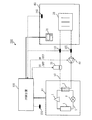
図1は、実施の形態1に係るヒートポンプシステム200の構成図である。
ヒートポンプシステム200は、ヒートポンプ装置10、補助熱源20、室内空間60に設置された放熱器30(流体利用装置の一例)、ポンプ40を備え、順次流体配管50によって接続されている。なお、流体配管50は、ヒートポンプ装置10が備える熱交換器2に接続されている。また、流体配管50の内部には、水(流体の一例)が流れている。
また、放熱器30が設置された室内空間60には、設定温度等を入力するためのリモートコントローラ70が設けられている。
FIG. 1 is a configuration diagram of a
The
In addition, a
ヒートポンプ装置10は、圧縮機1と熱交換器2と膨張機構3と熱交換器4とが冷媒配管5により順次接続されたヒートポンプサイクルを有する。圧縮機1、熱交換器2、膨張機構3、熱交換器4の順にヒートポンプサイクル内を冷媒が循環することにより、冷媒は、熱交換器4で空気等から吸熱して、熱交換器2で流体配管50を流れる水へ放熱する。つまり、ヒートポンプ装置10により、流体配管50を流れる水が加熱され、温水になる。
補助熱源20は、ヒートポンプ装置10が加熱した温水を、さらに加熱する。例えば、補助熱源20は、電気ヒータ等である。
放熱器30は、ヒートポンプ装置10や補助熱源20により加熱された温水の熱を、室内空間60の空気へ放出する。その結果、室内空間60内部は暖かくなり、温水は冷却され冷水になる。例えば、放熱器30は、輻射熱による自然対流の熱交換により温水と空気とを熱交換させる床暖房パネルやパネルヒータ、内部ファンによる強制対流の熱交換により温水と空気とを熱交換させるファンコイルユニット等である。
ポンプ40は、流体配管50内を水を循環させる。つまり、ポンプ40が稼動することにより、ヒートポンプ装置10、補助熱源20、放熱器30の順に水が循環する。そして、上述したように、水は、ヒートポンプ装置10で加熱され、補助熱源20でさらに加熱され、放熱器30で冷却されることを繰り返す。これにより、室内空間60が暖められる。
The
The
The
The
また、ヒートポンプシステム200は、温度センサ101〜104を備える。
温度センサ101(流入温度計測部)は、放熱器30へ流入する水の温度を流入温度として計測する。温度センサ102(流出温度計測部)は、放熱器30から流出した水の温度を流出温度として計測する。温度センサ103(室内温度計測部)は、室内空間60の空気の温度を室内温度として計測する。温度センサ104(外気温度計測部)は、外気の温度を計測する。
The
The temperature sensor 101 (inflow temperature measurement unit) measures the temperature of water flowing into the
さらに、ヒートポンプシステム200は、マイクロコンピュータ等により構成される制御装置100を備える。
制御装置100は、温度センサ101〜104が計測する温度や、リモートコントローラ70により入力される設定温度や、ヒートポンプ装置10(圧縮機1)の運転周波数等を取得する。制御装置100は、取得した情報に基づき目標温度を設定し、放熱器30へ供給する水の温度が目標温度になるように、ヒートポンプ装置10を制御する。また、制御装置100は、取得した情報に基づき、補助熱源20のON/OFFや、ポンプ40のON/OFFを制御する。
Furthermore, the
The
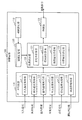
図2は、実施の形態1に係る制御装置100の構成図である。
制御装置100は、データ収集部110、温度設定部120、制御部130、閾値記憶部140、閾値設定部150を備える。
FIG. 2 is a configuration diagram of the
The
データ収集部110は、流入温度取得部111、流出温度取得部112、室内温度取得部113、外気温度取得部114、設定温度取得部115、周波数取得部116を備える。
流入温度取得部111は、温度センサ101が計測した流入温度を取得する。流出温度取得部112は、温度センサ102が計測した流出温度を取得する。室内温度取得部113は、温度センサ103が計測した室内温度を取得する。外気温度取得部114は、温度センサ104が計測した外気温度を取得する。設定温度取得部115は、リモートコントローラ70により入力された設定温度を取得する。周波数取得部116は、ヒートポンプ装置10から運転周波数を取得する。
The
The inflow temperature acquisition unit 111 acquires the inflow temperature measured by the
温度設定部120は、変化率計算部121、収束値計算部122、最低温度設定部123、目標温度設定部124を備える。
The
変化率計算部121は、流入温度取得部111が取得した流入温度に基づき、所定の時間(ここでは、一例として30秒とする)当たりの流入温度の変化率を、ヒートポンプ装置10の運転開始から設定時間(ここでは、一例として15秒とする)毎に計算する。また、変化率計算部121は、流出温度取得部112が取得した流出温度に基づき、所定の時間(30秒)当たりの流出温度の変化率を、ヒートポンプ装置10の運転開始から設定時間(15秒)毎に計算する。
なお、流入温度の変化率は、ある時刻において計測された流入温度と、その時刻の所定時間(30秒)前の時刻において計測された流入温度とから計算することができる。流出温度の変化率についても、流入温度の変化率と同様に計算できる。
流入温度の変化率を流入温度変化率と呼び、流出温度の変化率を流出温度変化率と呼ぶ。
Based on the inflow temperature acquired by the inflow temperature acquisition unit 111, the change
The change rate of the inflow temperature can be calculated from the inflow temperature measured at a certain time and the inflow temperature measured at a time before a predetermined time (30 seconds) before that time. The change rate of the outflow temperature can be calculated in the same manner as the change rate of the inflow temperature.
The rate of change of the inflow temperature is called the rate of change of the inflow temperature, and the rate of change of the outflow temperature is called the rate of change of the outflow temperature.
収束値計算部122は、流入温度取得部111が取得した流入温度に基づき、流入温度の収束値を、ヒートポンプ装置10の運転開始から設定時間(15秒)毎に計算する。また、収束値計算部122は、流出温度取得部112が取得した流出温度に基づき、流出温度の収束値を、ヒートポンプ装置10の運転開始から設定時間(15秒)毎に計算する。
なお、流入温度の収束値は、例えば、ある3つの時刻において計測された流入温度から、流入温度の変化の曲線を計算することにより、計算することができる。流出温度の収束値についても、流入温度の収束値と同様に計算できる。
流入温度の収束値を流入温度収束値と呼び、流出温度の収束値を流出温度収束値と呼ぶ。
The convergence
The convergence value of the inflow temperature can be calculated, for example, by calculating a curve of the change in inflow temperature from the inflow temperature measured at a certain three times. The convergence value of the outflow temperature can be calculated in the same manner as the convergence value of the inflow temperature.
The convergence value of the inflow temperature is called the inflow temperature convergence value, and the convergence value of the outflow temperature is called the outflow temperature convergence value.
最低温度設定部123は、変化率計算部121が計算した流入温度変化率及び流出温度変化率と、収束値計算部122が計算した流入温度収束値及び流出温度収束値と、流入温度取得部111が取得した流入温度と、流出温度取得部112が取得した流出温度とに基づき、最低温度を設定する。
具体的には、最低温度設定部123は、流入温度変化率と流出温度変化率との差が、後述する閾値記憶部140に記憶された変化率閾値以下であり、かつ、流入温度収束値と流出温度収束値との差が、閾値記憶部140に記憶された収束値閾値以下であり、かつ、流入温度と流出温度との差が、閾値記憶部140に記憶された温度閾値以下である場合における流入温度を、最低温度として設定する。
The minimum
Specifically, the minimum
目標温度設定部124は、室内温度取得部113が取得した室内温度や、外気温度取得部114が取得した外気温度や、設定温度取得部115が取得した設定温度や、周波数取得部116が取得した運転周波数等に基づき、最低温度設定部123が設定した最低温度以上の温度を目標温度として設定する。
なお、目標温度設定部124が目標温度を計算する方法については、従来から様々な方法が取られているが、どのようなものであっても構わない。但し、計算された目標温度が、最低温度よりも低い場合には、目標温度設定部124は最低温度を目標温度とする。
The target
Note that various methods have been conventionally used for the target
制御部130は、目標温度設定部124が設定した目標温度に流入温度がなるように、ヒートポンプ装置10を制御する。なお、ヒートポンプ装置10だけでは加熱量が足りない場合には、補助熱源20をONすることにより、目標温度に流入温度がなるようにする。
The
閾値記憶部140は、変化率閾値と、収束値閾値と、温度閾値とが記憶される記憶装置である。
The threshold
閾値設定部150は、変化率閾値や収束値閾値や温度閾値を閾値記憶部140に格納する。
閾値設定部150は、例えば、冬季等、負荷が高い(負荷が所定値以上)の場合における流入温度と流出温度との差の平均値を、収束値閾値や温度閾値として閾値記憶部140に格納する。また、閾値設定部150は、リモートコントローラ70等から入力された変化率閾値を閾値記憶部140に格納する。
The threshold
The
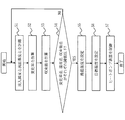
図3は、実施の形態1に係る制御装置100の制御処理の流れを示すフローチャートである。また、図4は、実施の形態1に係る制御装置100の制御処理の説明図である。
制御装置100は、ヒートポンプ装置10が運転を開始すると、図3に示す制御処理を開始する。図4では、t0の時点において、ヒートポンプ装置10が運転を開始した状態を示している。また、図4では、設定時間(15秒)毎に、t1,t2,...という目盛が付けられている。
なお、ヒートポンプ装置10の運転開始時には、ヒートポンプ装置10は定格周波数等の所定の周波数で制御される。
FIG. 3 is a flowchart showing a flow of control processing of the
When the
At the start of operation of the
(S1:温度計測処理)
流入温度取得部111は、温度センサ101により計測された流入温度を設定時間(15秒)毎に取得し、流出温度取得部112は、温度センサ102により計測された流出温度を設定時間(15秒)毎に取得する。
図4では、t0(運転開始から0秒後),t1(運転開始から15秒後),t2(運転開始から30秒後),・・・というように運転開始から15秒毎に流入温度と、流出温度が計測されることを示している。
(S1: Temperature measurement process)
The inflow temperature acquisition unit 111 acquires the inflow temperature measured by the
In FIG. 4, t 0 (0 seconds after the start of operation), t 1 (15 seconds after the start of operation), t 2 (30 seconds after the start of operation),... It shows that the inflow temperature and the outflow temperature are measured.
(S2:変化率計算処理)
変化率計算部121は、S1で取得した最新の流入温度と、その所定時間(30秒)前の流入温度とから、その時点における流入温度変化率を計算する。また、変化率計算部121は、S1で取得した最新の流出温度と、所定時間(30秒)前の流出温度とから、その時点における流出温度変化率を計算する。
例えば、図4では、運転開始から30秒が経過したt2の時点から15秒毎に流入温度変化率と流出温度変化率とが計算される。例えば、図4におけるtnの時点において、tnの時点で計測された流入温度と、tn−2の時点で計測された流入温度とから、流入温度変化率が計算される。同様に、図4におけるtnの時点において、tnの時点で計測された流出温度と、tn−2の時点で計測された流出温度とから、流出温度変化率が計算される。
(S2: Change rate calculation process)
The change
For example, in FIG. 4, the inflow temperature change rate and the outflow temperature change rate are calculated every 15 seconds from time t 2 when 30 seconds have elapsed from the start of operation. For example, at a time point t n in FIG. 4, the inflow temperature measured at time t n, from the inlet temperature measured at time t n-2, the inflow rate of temperature change is calculated. Similarly, at a time point t n in FIG. 4, the outflow temperature measured at time t n, from the outlet temperature measured at time t n-2, the outflow rate of temperature change is calculated.
(S3:収束値計算処理)
収束値計算部122は、S1で取得した最新の流入温度と、設定時間(15秒)前の流入温度と、さらに設定時間(15秒)前(つまり、30秒前)の流入温度とから、その時点における流入温度収束値を計算する。また、収束値計算部122は、S1で取得した最新の流出温度と、設定時間(15秒)前の流出温度と、さらに設定時間(15秒)前の流出温度とから、その時点における流出温度収束値を計算する。
例えば、図4では、運転開始から30秒が経過したt2の時点から15秒毎に流入温度収束値と流出温度収束値とが計算される。例えば、図4におけるtnの時点において、tn,tn−1,tn−2の各時点で計測された流入温度から、流入温度収束値が計算される。同様に、図4におけるtnの時点において、tn,tn−1,tn−2の各時点で計測された流出温度から、流出温度収束値が計算される。
(S3: convergence value calculation process)
The convergence
For example, in FIG. 4, the inlet temperature convergence value every 15 seconds from the time of t 2 to 30 seconds from the start of operation has elapsed and an outlet temperature convergence value is calculated. For example, at a time point t n in FIG. 4, t n, from the inlet temperature measured at each time point t n-1, t n-2, inlet temperature convergence value is calculated. Similarly, at a time point t n in FIG. 4, t n, from the outflow temperature measured at each time point t n-1, t n-2, the outflow temperature convergence value is calculated.
(S4:判定処理)
最低温度設定部123は、流入温度変化率と流出温度変化率との差(変化率差)が変化率閾値以下であり、かつ、流入温度収束値と流出温度収束値との差(収束値差)が収束値閾値以下であり、かつ、流入温度と流出温度との差(温度差)が温度閾値以下であるか否かを判定する。
最低温度設定部123は、全て閾値以下である場合(S4でYES)、処理をS5へ進める。一方、最低温度設定部123は、いずれか1つでも閾値より高い場合(S4でNO)、S1へ処理を戻して設定時間(15秒)後における変化率差、収束値差、温度差の各値について判定する。
例えば、図4のtnの時点における変化率差が変化率閾値以下であり、かつ、tnの時点における収束値差が収束値閾値以下であり、かつ、tnの時点における温度差が温度閾値以下であるか否かが判定される。そして、全て閾値以下である場合(S4でYES)、処理をS5へ進め、いずれか1つでも閾値より高い場合(S4でNO)、S1へ処理を戻して、tn+1の時点における各値について判定する。
(S4: Determination process)
The minimum
If all the temperatures are below the threshold (YES in S4), the minimum
For example, a change rate difference is less change rate threshold at the time of t n in FIG. 4, and the convergence value difference at the time of t n is less than the convergence value threshold, and the temperature difference at the time of t n the temperature It is determined whether it is below the threshold value. If all are below the threshold (YES in S4), the process proceeds to S5, and if any one is higher than the threshold (NO in S4), the process returns to S1, and each value at the time point of t n + 1 judge.
(S5:最低温度設定処理)
最低温度設定部123は、S4で全て閾値以下であると判定した時点における流入温度を最低温度として設定する。
例えば、S4で図4におけるtnの時点における各値が閾値以下であると判定された場合、tnにおいて計測された流入温度Minを最低温度として設定する。
(S5: Minimum temperature setting process)
The minimum
For example, if it is determined that the value is equal to or smaller than the threshold at the time of t n in FIG. 4 at S4, it sets the inlet temperature Min measured in t n as the minimum temperature.
(S6:目標温度設定処理)
目標温度設定部124は、所定の方法により、目標温度を計算する。この際、計算した目標温度がS5で設定された最低温度より低い場合、目標温度をS5で設定された最低温度とする。これにより、目標温度として、最低温度以上の温度が設定される。
(S6: target temperature setting process)
The target
(S7:制御処理)
制御部130は、流入温度がS6で設定された目標温度になるように、ヒートポンプ装置10を制御する。
(S7: Control processing)
The
図4に示すように、ヒートポンプ装置10が運転を開始すると、流入温度はすぐに上がり始めるが、流出温度はしばらく時間(図4ではT)が経ってから温度が上がり始める。この流入温度が上がり始める時刻と、流出温度が上がり始める時刻との時間差Tは、水が温度センサ101を通過してから、放熱器30を通過して、温度センサ102へ戻ってくるまでの時間である。ヒートポンプシステム200毎に、放熱器30の配置の仕方や、放熱器30の台数等が異なり、放熱器30を繋ぐ流体配管50の長さは異なる。そのため、水が温度センサ101を通過してから温度センサ102へ戻ってくるまでの時間は、ヒートポンプシステム200毎に異なる。
また、設置される放熱器30の能力や、暖房負荷等によって、流入温度や流出温度の変化曲線は異なる。
As shown in FIG. 4, when the
Moreover, the change curves of the inflow temperature and the outflow temperature vary depending on the capacity of the
実施の形態1に係るヒートポンプシステム200では、流入温度と流出温度とを用いた計算により最低温度を設定する。そのため、ヒートポンプシステム200毎に異なる流体配管50の長さや、放熱器30の能力、暖房負荷等を考慮した最低温度を設定することができる。
したがって、低すぎる目標温度が設定されたことが原因となり、ヒートポンプ装置10のON/OFFが繰り返されることを防止でき、ヒートポンプ装置10の連続運転を実現することができる。よって、省エネルギー化を進めることができる。
In
Therefore, it is possible to prevent the
特に、実施の形態1に係るヒートポンプシステム200では、温度閾値と収束値閾値とを、冬等の暖房負荷が高い場合における流入温度と流出温度との温度差に基づき定めている。そのため、ヒートポンプシステム200毎に適切な温度閾値と収束値閾値とを定めることが可能である。したがって、最低温度も適切に設定することができる。
In particular, in the
なお、図3のS5において、最低温度設定部123は、周波数取得部116が取得した運転周波数に基づき、最低温度を補正してもよい。ヒートポンプ装置10は通常定格周波数に近い周波数でした方が効率がよい。そこで、最低温度設定部123は、ヒートポンプ装置10の運転周波数が定格周波数に近くなるように、最低温度を補正してもよい。
さらに、図3のS5において、最低温度設定部123は、外気温度取得部114が取得した外気温度に基づき、最低温度を補正してもよい。ヒートポンプ装置10の運転効率と、運転周波数との関係を表す曲線は、外気温度により変化する。そこで、最低温度設定部123は、外気温度を考慮して、ヒートポンプ装置10の運転周波数が定格周波数に近くなるように、最低温度を補正してもよい。
また、図3のS5において、最低温度設定部123は、室内温度取得部113が取得した室内温度や設定温度取得部115が取得した設定温度に基づき、最低温度を補正してもよい。例えば、最低温度設定部123は、設定した最低温度で運転した場合に、室内温度が設定温度を超えてしまうような場合には、最低温度を低くするように補正してもよい。
In S <b> 5 of FIG. 3, the minimum
Furthermore, in S5 of FIG. 3, the minimum
3, the minimum
また、上記説明では、変化率差と収束値差と温度差との3つの指標に基づき、最低温度を設定した。しかし、変化率差と収束値差と温度差といずれか1つのみ、あるいは、いずれか2つのみの指標に基づき、最低温度を設定してもよい。 In the above description, the minimum temperature is set based on the three indicators of the change rate difference, the convergence value difference, and the temperature difference. However, the minimum temperature may be set based on only one of the change rate difference, the convergence value difference, and the temperature difference, or only two of the indexes.
1 圧縮機、2 熱交換器、3 膨張機構、4 熱交換器、5 冷媒配管、10 ヒートポンプ装置、20 補助熱源、30 放熱器、40 ポンプ、50 流体配管、60 室内空間、70 リモートコントローラ、100 制御装置、101,102,103,104 温度センサ、110 データ収集部、111 流入温度取得部、112 流出温度取得部、113 室内温度取得部、114 外気温度取得部、115 設定温度取得部、116 周波数取得部、120 温度設定部、121 変化率計算部、122 収束値計算部、123 最低温度設定部、124 目標温度設定部、130 制御部、140 閾値記憶部、150 閾値設定部、200 ヒートポンプシステム。
DESCRIPTION OF
Claims (8)
前記流体利用装置へ流入する前記流体の温度を流入温度として計測する流入温度計測部と、
前記流体利用装置から流出する前記流体の温度を流出温度として計測する流出温度計測部と、
前記流入温度計測部が計測した流入温度の所定の時間当たりの変化率を流入温度変化率として前記圧縮機の運転開始から順次計算するとともに、前記流出温度計測部が計測した流出温度の前記所定の時間当たりの変化率を流出温度変化率として前記圧縮機の運転開始から順次計算する変化率計算部と、
前記変化率計算部が計算した前記流入温度変化率と前記流出温度変化率との差が予め設定された変化率閾値以下となった場合における前記流入温度を最低温度として設定する最低温度設定部と、
前記最低温度設定部が設定した最低温度以上の温度を目標温度として設定する目標温度設定部と、
前記流体利用装置へ流入する前記流体の温度が、前記目標温度設定部が設定した目標温度になるように、前記ヒートポンプ装置が有する前記圧縮機を制御する制御部と
を備えることを特徴とするヒートポンプシステム。 A heat pump system comprising a heat pump device having a compressor and supplying a fluid heated by the heat pump device to a fluid utilization device utilizing the fluid;
An inflow temperature measurement unit that measures the temperature of the fluid flowing into the fluid utilization device as an inflow temperature;
An outflow temperature measurement unit that measures the temperature of the fluid flowing out of the fluid utilization device as an outflow temperature;
The rate of change per unit time of the inflow temperature measured by the inflow temperature measurement unit is sequentially calculated from the start of operation of the compressor as the rate of change of inflow temperature, and the predetermined temperature of the outflow temperature measured by the outflow temperature measurement unit is calculated. A rate of change calculation unit that sequentially calculates the rate of change per hour from the start of operation of the compressor as an outflow temperature change rate;
A minimum temperature setting unit that sets the inflow temperature as a minimum temperature when a difference between the inflow temperature change rate calculated by the change rate calculation unit and the outflow temperature change rate is equal to or less than a preset change rate threshold; ,
A target temperature setting unit that sets a temperature equal to or higher than the minimum temperature set by the minimum temperature setting unit as a target temperature;
And a control unit that controls the compressor of the heat pump device so that the temperature of the fluid flowing into the fluid utilization device becomes a target temperature set by the target temperature setting unit. system.
ことを特徴とする請求項1に記載のヒートポンプシステム。 The minimum temperature setting unit is configured such that a difference between the inflow temperature change rate and the outflow temperature change rate is equal to or less than the change rate threshold value, and a difference between the inflow temperature and the outflow temperature is equal to or less than a preset temperature threshold value. The heat pump system according to claim 1, wherein the inflow temperature in the case of becoming a minimum temperature is set as a minimum temperature.
前記流入温度計測部が計測した流入温度の変化から前記流入温度の収束値を流入温度収束値として前記圧縮機の運転開始から順次計算するとともに、前記流出温度計測部が計測した流出温度の変化から前記流出温度の収束値を流出温度収束値として前記圧縮機の運転開始から順次計算する収束値計算部
を備え、
前記最低温度設定部は、前記流入温度変化率と前記流出温度変化率との差が前記変化率閾値以下となり、かつ、前記流入温度と前記流出温度との差が前記温度閾値以下となり、かつ、前記収束値計算部が計算した前記流入温度収束値と前記流出温度収束値との差が予め設定された収束値閾値以下となった場合における前記流入温度を最低温度として設定する
ことを特徴とする請求項2に記載のヒートポンプシステム。 The heat pump system further includes:
From the change of the inflow temperature measured by the outflow temperature measurement unit, the convergence value of the inflow temperature is sequentially calculated from the start of operation of the compressor as the inflow temperature convergence value from the change in inflow temperature measured by the inflow temperature measurement unit. A convergence value calculation unit that sequentially calculates from the start of operation of the compressor as the outflow temperature convergence value the convergence value of the outflow temperature,
The minimum temperature setting unit has a difference between the rate of change of the inflow temperature and the rate of change of the outflow temperature of not more than the threshold value of the change rate, and a difference of the inflow temperature and the outflow temperature of not more than the temperature threshold value, and The inflow temperature when the difference between the inflow temperature convergence value calculated by the convergence value calculation unit and the outflow temperature convergence value is equal to or less than a predetermined convergence value threshold value is set as a minimum temperature. The heat pump system according to claim 2.
ことを特徴とする請求項1から3までのいずれかに記載のヒートポンプシステム。 The said minimum temperature setting part correct | amends the set said minimum temperature according to the operating frequency of the said compressor in the time of setting the said minimum temperature, The one in any one of Claim 1 to 3 characterized by the above-mentioned. Heat pump system.
外気温度を計測する外気温度計測部
を備え、
前記最低温度設定部は、前記外気温度計測部が計測した外気温度に応じて、前記最低温度を補正する
ことを特徴とする請求項1から4までのいずれかに記載のヒートポンプシステム。 The heat pump system further includes:
It has an outside air temperature measurement unit that measures the outside air temperature,
The heat pump system according to any one of claims 1 to 4, wherein the minimum temperature setting unit corrects the minimum temperature in accordance with an outside air temperature measured by the outside air temperature measurement unit.
前記ヒートポンプシステムは、さらに、
前記部屋の設定温度を取得する設定温度取得部
を備え、
前記最低温度設定部は、前記設定温度取得部が取得した設定温度に応じて、前記最低温度を補正する
ことを特徴とする請求項1から5までのいずれかに記載のヒートポンプシステム。 The fluid utilization device is a heat exchanger that exchanges heat between the fluid and air in a predetermined room,
The heat pump system further includes:
A set temperature acquisition unit for acquiring the set temperature of the room;
The heat pump system according to any one of claims 1 to 5, wherein the minimum temperature setting unit corrects the minimum temperature in accordance with the set temperature acquired by the set temperature acquisition unit.
暖房負荷が所定値以上の場合における前記流入温度と前記流出温度との温度差を前記温度閾値として設定する閾値設定部
を備えることを特徴とする請求項2に記載のヒートポンプシステム。 The heat pump system further includes:
The heat pump system according to claim 2, further comprising a threshold setting unit configured to set a temperature difference between the inflow temperature and the outflow temperature when the heating load is equal to or greater than a predetermined value as the temperature threshold.
前記流体利用装置へ流入する前記流体の温度を流入温度として計測する流入温度計測工程と、
前記流体利用装置から流出する前記流体の温度を流出温度として計測する流出温度計測工程と、
前記流入温度計測工程で計測した流入温度の所定の時間当たりの変化率を流入温度変化率として前記圧縮機の運転開始から順次計算するとともに、前記流出温度計測工程で計測した流出温度の前記所定の時間当たりの変化率を流出温度変化率として前記圧縮機の運転開始から順次計算する変化率計算工程と、
前記変化率計算工程で計算した前記流入温度変化率と前記流出温度変化率との差が予め設定された変化率閾値以下となった場合における前記流入温度を最低温度として設定する最低温度設定工程と、
前記最低温度設定工程で設定した最低温度以上の温度を目標温度として設定する目標温度設定工程と、
前記流体利用装置へ流入する前記流体の温度が、前記目標温度設定工程で設定した目標温度になるように、前記ヒートポンプ装置が有する前記圧縮機を制御する制御工程と
を備えることを特徴とするヒートポンプ装置の制御方法。 A control method for the heat pump device in a heat pump system comprising a heat pump device having a compressor and supplying a fluid heated by the heat pump device to a fluid utilization device using the fluid;
An inflow temperature measuring step of measuring the temperature of the fluid flowing into the fluid utilization device as an inflow temperature;
An outflow temperature measuring step of measuring the temperature of the fluid flowing out of the fluid utilization device as an outflow temperature;
The rate of change per unit time of the inflow temperature measured in the inflow temperature measurement step is sequentially calculated from the start of operation of the compressor as the inflow temperature change rate, and the predetermined outflow temperature measured in the outflow temperature measurement step is calculated. A rate of change calculation step for sequentially calculating the rate of change per hour as the outflow temperature change rate from the start of operation of the compressor;
A minimum temperature setting step for setting the inflow temperature as a minimum temperature when a difference between the inflow temperature change rate calculated in the change rate calculation step and the outflow temperature change rate is equal to or less than a preset change rate threshold; ,
A target temperature setting step of setting a temperature equal to or higher than the minimum temperature set in the minimum temperature setting step as a target temperature;
And a control step of controlling the compressor of the heat pump device so that the temperature of the fluid flowing into the fluid utilization device becomes the target temperature set in the target temperature setting step. Control method of the device.
Priority Applications (3)
| Application Number | Priority Date | Filing Date | Title |
|---|---|---|---|
| JP2011085679A JP5501282B2 (en) | 2011-04-07 | 2011-04-07 | HEAT PUMP SYSTEM AND HEAT PUMP SYSTEM CONTROL METHOD |
| EP12001735.5A EP2508806B1 (en) | 2011-04-07 | 2012-03-14 | Heat pump system and heat pump unit controlling method |
| CN201210099487.4A CN102734983B (en) | 2011-04-07 | 2012-04-06 | Heat pump system and heat pump unit controlling method |
Applications Claiming Priority (1)
| Application Number | Priority Date | Filing Date | Title |
|---|---|---|---|
| JP2011085679A JP5501282B2 (en) | 2011-04-07 | 2011-04-07 | HEAT PUMP SYSTEM AND HEAT PUMP SYSTEM CONTROL METHOD |
Publications (2)
| Publication Number | Publication Date |
|---|---|
| JP2012220086A JP2012220086A (en) | 2012-11-12 |
| JP5501282B2 true JP5501282B2 (en) | 2014-05-21 |
Family
ID=45893995
Family Applications (1)
| Application Number | Title | Priority Date | Filing Date |
|---|---|---|---|
| JP2011085679A Expired - Fee Related JP5501282B2 (en) | 2011-04-07 | 2011-04-07 | HEAT PUMP SYSTEM AND HEAT PUMP SYSTEM CONTROL METHOD |
Country Status (3)
| Country | Link |
|---|---|
| EP (1) | EP2508806B1 (en) |
| JP (1) | JP5501282B2 (en) |
| CN (1) | CN102734983B (en) |
Cited By (1)
| Publication number | Priority date | Publication date | Assignee | Title |
|---|---|---|---|---|
| CN105318460A (en) * | 2015-10-15 | 2016-02-10 | 珠海格力电器股份有限公司 | Control system, control method and water chilling unit applying control system and control method |
Families Citing this family (7)
| Publication number | Priority date | Publication date | Assignee | Title |
|---|---|---|---|---|
| JP6615530B2 (en) * | 2015-08-10 | 2019-12-04 | キヤノンメディカルシステムズ株式会社 | Magnetic resonance imaging system |
| CN105928326B (en) * | 2016-05-09 | 2018-04-06 | 顺德职业技术学院 | Band flash vessel air injection enthalpy-increasing heat pump vacuum freeze drying unit equipment energy-saving control method |
| CN106091103B (en) * | 2016-07-01 | 2018-05-29 | 顺德职业技术学院 | Constant temperature water supply determines frequency heat-pump hot-water Energy conservation measures in heating system |
| CN106016760B (en) * | 2016-07-01 | 2018-04-13 | 顺德职业技术学院 | Self-adapting frequency conversion heat-pump hot-water Energy conservation measures in heating system |
| EP3379158B1 (en) * | 2017-03-24 | 2020-02-19 | Mitsubishi Electric R&D Centre Europe B.V. | Method for operating a heat pump system |
| DE102017123560B4 (en) * | 2017-10-10 | 2024-09-12 | Eut Edelstahl Umformtechnik Gmbh | Self-regulating adjustment device for a flow control valve |
| CN114608052A (en) * | 2022-02-25 | 2022-06-10 | 北京市京海换热设备制造有限责任公司 | Combined heat and power distributed heating plant device |
Family Cites Families (15)
| Publication number | Priority date | Publication date | Assignee | Title |
|---|---|---|---|---|
| DE3423262A1 (en) * | 1983-07-30 | 1985-02-07 | Joh. Vaillant Gmbh U. Co, 5630 Remscheid | Method for regulating a heat pump in association with a further heat source |
| JPH0827000B2 (en) * | 1987-02-25 | 1996-03-21 | 松下電器産業株式会社 | Hot water heating system |
| JP2802349B2 (en) * | 1989-11-15 | 1998-09-24 | 株式会社ハーマン | Heat source equipment |
| JPH06323556A (en) * | 1993-05-11 | 1994-11-25 | Noritz Corp | Hot-water heater |
| US5623426A (en) * | 1994-02-23 | 1997-04-22 | Sanyo Electric Co., Ltd. | Failure diagnosing system for absorption chillers |
| JP3888403B2 (en) * | 1997-12-18 | 2007-03-07 | 株式会社富士通ゼネラル | Method and apparatus for controlling air conditioner |
| JP2004132612A (en) * | 2002-10-10 | 2004-04-30 | Mitsubishi Electric Corp | Heating and air conditioning system, and dwelling house with heating and air conditioning system |
| KR20070106043A (en) * | 2003-11-28 | 2007-10-31 | 미쓰비시덴키 가부시키가이샤 | Freezer and air conditioner |
| JP4711852B2 (en) * | 2006-02-24 | 2011-06-29 | 三菱電機株式会社 | Temperature adjusting device and refrigeration cycle |
| JP5073970B2 (en) * | 2006-06-01 | 2012-11-14 | 日立アプライアンス株式会社 | Heat pump hot water floor heater |
| JP4923812B2 (en) * | 2006-07-24 | 2012-04-25 | 株式会社デンソー | Brine heat dissipation heating system |
| JP5216368B2 (en) * | 2008-02-29 | 2013-06-19 | 日立アプライアンス株式会社 | Heat pump water heater |
| JP5481942B2 (en) * | 2008-05-30 | 2014-04-23 | ダイキン工業株式会社 | Heating system |
| JP5242434B2 (en) * | 2009-01-30 | 2013-07-24 | パナソニック株式会社 | Liquid circulation heating system |
| JP5371575B2 (en) * | 2009-06-23 | 2013-12-18 | アズビル株式会社 | Air conditioning operation device and air conditioning operation method |
-
2011
- 2011-04-07 JP JP2011085679A patent/JP5501282B2/en not_active Expired - Fee Related
-
2012
- 2012-03-14 EP EP12001735.5A patent/EP2508806B1/en not_active Not-in-force
- 2012-04-06 CN CN201210099487.4A patent/CN102734983B/en active Active
Cited By (2)
| Publication number | Priority date | Publication date | Assignee | Title |
|---|---|---|---|---|
| CN105318460A (en) * | 2015-10-15 | 2016-02-10 | 珠海格力电器股份有限公司 | Control system, control method and water chilling unit applying control system and control method |
| CN105318460B (en) * | 2015-10-15 | 2018-01-23 | 珠海格力电器股份有限公司 | Control system, control method and water chilling unit applying control system and control method |
Also Published As
| Publication number | Publication date |
|---|---|
| EP2508806A2 (en) | 2012-10-10 |
| JP2012220086A (en) | 2012-11-12 |
| EP2508806A3 (en) | 2016-09-21 |
| CN102734983B (en) | 2014-08-06 |
| EP2508806B1 (en) | 2017-09-27 |
| CN102734983A (en) | 2012-10-17 |
Similar Documents
| Publication | Publication Date | Title |
|---|---|---|
| JP5501282B2 (en) | HEAT PUMP SYSTEM AND HEAT PUMP SYSTEM CONTROL METHOD | |
| JP5452581B2 (en) | HEAT PUMP SYSTEM AND HEAT PUMP DEVICE CONTROL METHOD | |
| JP5216368B2 (en) | Heat pump water heater | |
| EP3252383A1 (en) | Apparatus for space heating and warm water supply | |
| JP2011112235A (en) | Unit number control device, unit number control method, and fluid supply system | |
| JP6570766B2 (en) | Heating control system and heat pump hot water supply heating system | |
| JP2009014218A (en) | Hot water heating device | |
| JP6914428B2 (en) | Control unit, outdoor unit, heat source unit and air conditioning system | |
| JP2010243002A (en) | Air conditioning system | |
| JP2007078200A (en) | Heat pump water heater | |
| JP5215039B2 (en) | Control method for hot water heater | |
| EP3258185A1 (en) | Heat supply system | |
| JP2017067321A (en) | Heat pump control device, hot water supply unit of heat pump-type heating system, heat pump-type heating system, and method executed by heat pump control device | |
| JP5582059B2 (en) | Heat pump hot water heater | |
| JP5701084B2 (en) | Heating system | |
| JP3850653B2 (en) | Heat pump type water heater | |
| JP6537636B2 (en) | Heating system | |
| JP2004037024A (en) | Warm water circulating floor heating apparatus | |
| JP5818601B2 (en) | Heat pump heat source machine | |
| JP4157074B2 (en) | Heating control device | |
| JP6361021B2 (en) | Hot water generator | |
| JP5313087B2 (en) | Hot water storage hot water heater | |
| JP2008145046A (en) | Automatic bath warmth keeping device | |
| JP2005009687A (en) | Floor heating system | |
| JP2010139093A (en) | Heat pump water heater |
Legal Events
| Date | Code | Title | Description |
|---|---|---|---|
| A621 | Written request for application examination |
Free format text: JAPANESE INTERMEDIATE CODE: A621 Effective date: 20130611 |
|
| A977 | Report on retrieval |
Free format text: JAPANESE INTERMEDIATE CODE: A971007 Effective date: 20140131 |
|
| TRDD | Decision of grant or rejection written | ||
| A01 | Written decision to grant a patent or to grant a registration (utility model) |
Free format text: JAPANESE INTERMEDIATE CODE: A01 Effective date: 20140212 |
|
| A61 | First payment of annual fees (during grant procedure) |
Free format text: JAPANESE INTERMEDIATE CODE: A61 Effective date: 20140311 |
|
| R150 | Certificate of patent or registration of utility model |
Ref document number: 5501282 Country of ref document: JP Free format text: JAPANESE INTERMEDIATE CODE: R150 |
|
| R250 | Receipt of annual fees |
Free format text: JAPANESE INTERMEDIATE CODE: R250 |
|
| R250 | Receipt of annual fees |
Free format text: JAPANESE INTERMEDIATE CODE: R250 |
|
| R250 | Receipt of annual fees |
Free format text: JAPANESE INTERMEDIATE CODE: R250 |
|
| R250 | Receipt of annual fees |
Free format text: JAPANESE INTERMEDIATE CODE: R250 |
|
| R250 | Receipt of annual fees |
Free format text: JAPANESE INTERMEDIATE CODE: R250 |
|
| LAPS | Cancellation because of no payment of annual fees |