JP5500766B2 - X-ray imaging device - Google Patents
X-ray imaging device Download PDFInfo
- Publication number
- JP5500766B2 JP5500766B2 JP2007127539A JP2007127539A JP5500766B2 JP 5500766 B2 JP5500766 B2 JP 5500766B2 JP 2007127539 A JP2007127539 A JP 2007127539A JP 2007127539 A JP2007127539 A JP 2007127539A JP 5500766 B2 JP5500766 B2 JP 5500766B2
- Authority
- JP
- Japan
- Prior art keywords
- subject
- imaging
- ray imaging
- ray
- unit
- Prior art date
- Legal status (The legal status is an assumption and is not a legal conclusion. Google has not performed a legal analysis and makes no representation as to the accuracy of the status listed.)
- Expired - Fee Related
Links
- 238000003384 imaging method Methods 0.000 title claims abstract description 107
- 238000013170 computed tomography imaging Methods 0.000 claims description 37
- 230000003028 elevating effect Effects 0.000 claims description 3
- 210000003141 lower extremity Anatomy 0.000 description 17
- 230000005855 radiation Effects 0.000 description 10
- 238000010586 diagram Methods 0.000 description 7
- 238000001514 detection method Methods 0.000 description 5
- 238000000034 method Methods 0.000 description 3
- 230000001174 ascending effect Effects 0.000 description 2
- 238000002591 computed tomography Methods 0.000 description 2
- 125000002066 L-histidyl group Chemical group [H]N1C([H])=NC(C([H])([H])[C@](C(=O)[*])([H])N([H])[H])=C1[H] 0.000 description 1
- 238000002247 constant time method Methods 0.000 description 1
- 238000003745 diagnosis Methods 0.000 description 1
- 201000010099 disease Diseases 0.000 description 1
- 208000037265 diseases, disorders, signs and symptoms Diseases 0.000 description 1
- 230000001771 impaired effect Effects 0.000 description 1
- 238000009434 installation Methods 0.000 description 1
- 230000001678 irradiating effect Effects 0.000 description 1
- 238000012216 screening Methods 0.000 description 1
- 230000000087 stabilizing effect Effects 0.000 description 1
Images


Classifications
-
- A—HUMAN NECESSITIES
- A61—MEDICAL OR VETERINARY SCIENCE; HYGIENE
- A61B—DIAGNOSIS; SURGERY; IDENTIFICATION
- A61B6/00—Apparatus for radiation diagnosis, e.g. combined with radiation therapy equipment
- A61B6/44—Constructional features of apparatus for radiation diagnosis
- A61B6/4476—Constructional features of apparatus for radiation diagnosis related to motor-assisted motion of the source unit
- A61B6/4482—Constructional features of apparatus for radiation diagnosis related to motor-assisted motion of the source unit involving power assist circuits
-
- A—HUMAN NECESSITIES
- A61—MEDICAL OR VETERINARY SCIENCE; HYGIENE
- A61B—DIAGNOSIS; SURGERY; IDENTIFICATION
- A61B6/00—Apparatus for radiation diagnosis, e.g. combined with radiation therapy equipment
- A61B6/10—Application or adaptation of safety means
- A61B6/102—Protection against mechanical damage, e.g. anti-collision devices
Abstract
Description
本発明は、被検者側を回転移動させながら、被検者の透過X線からX線画像を得るX線画像撮影装置に関するものである。 The present invention relates to an X-ray imaging apparatus that obtains an X-ray image from transmitted X-rays of a subject while rotating the subject side.
従来、被検者の外周から放射線を照射し、被検者を透過した放射線を検出して画像信号に変換し、この画像信号を再構成処理することにより、被検者の三次元断面画像を構築するCT装置(Computed Tomography)が、医療分野で利用されている。 Conventionally, radiation is irradiated from the outer periphery of the subject, the radiation transmitted through the subject is detected and converted into an image signal, and the image signal is reconstructed to obtain a three-dimensional cross-sectional image of the subject. The CT apparatus (Computed Tomography) to be constructed is used in the medical field.
このCT装置においては、被検者を挟んで放射線源と放射線検出器が対をなして構成され、被検者の仮想体軸を中心として被検者の周りを螺旋状に回転移動させながら、多数の回転位置で透過放射線の強度を検出するヘリカルスキャンCT方法が一般的である。 In this CT apparatus, a radiation source and a radiation detector are paired with the subject interposed therebetween, and while rotating around the subject in a spiral manner around the virtual body axis of the subject, A helical scan CT method that detects the intensity of transmitted radiation at a number of rotational positions is common.
一方、近年では固定した放射線源と放射線検出器間で、被検者側を回転させることにより断層画像を得る方法も提案されている。この種のCT装置では、放射線検出器として二次元形状をした平面センサを用い、コーン状の放射線を照射することにより、三次元画像の再構成に必要な透視画像を1回の走査で取得することができる。また、通常のCT装置では不可欠である体軸方向の連続移動を不要としている。 On the other hand, in recent years, a method of obtaining a tomographic image by rotating the subject side between a fixed radiation source and a radiation detector has been proposed. In this type of CT apparatus, a two-dimensional planar sensor is used as a radiation detector, and a fluoroscopic image necessary for reconstruction of a three-dimensional image is acquired by a single scan by irradiating cone-shaped radiation. be able to. Further, the continuous movement in the body axis direction, which is indispensable in a normal CT apparatus, is unnecessary.
被検者を回転して撮影を行う特許文献1による撮影方法では、被検者の安全を確保した上で、被検者の姿勢を安定させながら回転させる必要がある。そして、これに対する対応策を有する装置が提案されている。
In the imaging method according to
特許文献2では、被検者の体動を抑えるため、被検者を支持する支持部材を回転台上に設け、被検者を中腰姿勢で支持して撮影する装置が提案されている。また、特許文献1において、被検者の前方に下肢ガードを設けて、回転中の被検者の下肢が周囲の非回転部に接触することを防止する手段が開示されている。このようにして被検者を配置することにより、高スループットでCT撮影を行うことが可能となり、一般静止画撮影に代り胸部スクリーニングに応用されつつある。
Japanese Patent Application Laid-Open No. 2004-228561 proposes an apparatus for photographing a patient by supporting the subject in a middle waist posture by providing a support member on the rotating table in order to suppress body movement of the subject.
また、特許文献2において安全性を確保するため、被検者支持部材の状態情報を検出し、検知結果に応じて回転テーブルの回転を制御する装置が提案されている。
一方、放射線検出器として大型の二次元平面センサを用いるため、これらの撮影装置は一般的に高価なものとなっている。また、病院内における限られた設置スペースを有効に活用する上でも、1台の撮影装置を用いてCT撮影と一般静止画撮影との異なる撮影形態の双方を行うことが要望されている。これに対して特許文献1には被検者支持部材を移動して、X線照射範囲から退避することにより、回転台上にスペースを作って静止画撮影を行い、1台の装置でCT撮影と一般静止画撮影との兼用を可能にした撮影装置が記載されている。
On the other hand, since a large two-dimensional planar sensor is used as a radiation detector, these imaging apparatuses are generally expensive. In addition, in order to effectively utilize a limited installation space in a hospital, it is desired to perform both different imaging forms of CT imaging and general still image imaging using a single imaging apparatus. On the other hand, in
このような撮影装置でCT撮影を行う場合に、被検者とX線撮影部との距離は、再構成領域を広く確保するために、また画像のぼけを少なくするために、回転中に接触が生じない範囲で近付けることが望まれる。このため、実際の撮影において、X線撮影部の位置は特許文献1で示された配置よりも、被検者に近接した位置に配置する必要がある。
When performing CT imaging with such an imaging apparatus, the distance between the subject and the X-ray imaging unit is in contact during rotation in order to ensure a wide reconstruction area and to reduce image blurring. It is desirable that the distance is as close as possible. For this reason, in actual imaging, the position of the X-ray imaging unit needs to be arranged closer to the subject than the arrangement shown in
これにより、従来例の図5で示すようにX線管球1からのX線照射中に、回転テーブル2上の被検者Pの下肢Paが、回転中にX線撮影部3の下方を通過するような配置となる。また、被検者Pの前方に下肢ガード4を備えた場合には、下肢ガード4もX線撮影部3の下方を通過することになる。従って、CT撮影に際し、X線撮影部3の位置は上下の移動範囲L1内に設定する必要がある。
Thus, as shown in FIG. 5 of the conventional example, the lower limb Pa of the subject P on the rotary table 2 moves under the
一方、静止画撮影時には、特許文献1で示すように各被検者支持部材の下方に設けられた移動手段を用いて、被検者支持部材を撮影領域から退避させ、被検者はX線撮影部に接近し、X線撮影部の外装に密着して撮影を行う。
On the other hand, at the time of still image shooting, as shown in
一般静止画撮影では、全ゆる病気に対して最初に行われる検査においては、頭部から下肢まで全身の撮影が可能なことが望まれる。このため、X線撮影部3の上下位置はCT撮影に比較して、広範囲に移動できるように構成しておく必要がある。
In general still image photography, it is desired that the whole body can be photographed from the head to the lower limbs in the examination performed first for all diseases. For this reason, it is necessary to configure the vertical position of the
しかし、X線撮影部3の可動範囲を静止画撮影のために、広範囲に移動できるように構成しておくと、CT撮影においては必要以上にX線撮影部3が移動することになる。このため、不適切な低い位置に設定し、回転中にX線撮影部3と被検者支持部材や被検者Pの下肢Paとの接触が生じ安全性を損う虞れがある。安全性を確保するためには、X線撮影部3の位置設定に注意を必要とし、結果として操作性の低下を招く虞れがある。
However, if the movable range of the
撮影形態を変更した場合にも同様の問題が生じ、一般静止画撮影を低い位置で撮影した後に、被検者支持部材を移動してX線撮影部3をCT撮影形態に変更した場合に、その位置関係のまま回転テーブル2を回転してしまうと、前述のように安全性を損うことがある。
The same problem occurs when the imaging mode is changed, and after the general still image is captured at a low position, the subject support member is moved and the
また、被検者を回転して撮影を行う撮影装置において、平面センサを用いたCT装置では、通常のヘリカルスキャン方式のCT装置では必要とされる体軸方向の移動が不要である。逆に、CT撮影中は常に同じ高さで多角度から撮影が行われなければならず、X線撮影部の高さ調整が可能な撮影装置において、CT撮影中にX線撮影部の昇降が行われると、正しい画像取得ができず再構成ができない。従来装置では、回転中の昇降を強制的に禁止する手段を有していないため、撮影中に昇降が行われてしまう危険性がある。 In addition, in an imaging apparatus that performs imaging by rotating a subject, a CT apparatus using a planar sensor does not require movement in the body axis direction, which is necessary for a normal helical scan CT apparatus. Conversely, during CT imaging, imaging must always be performed from multiple angles at the same height, and in an imaging apparatus capable of adjusting the height of the X-ray imaging unit, the X-ray imaging unit can move up and down during CT imaging. If this is done, correct images cannot be acquired and reconstruction cannot be performed. Since the conventional apparatus does not have means for forcibly prohibiting the raising / lowering during rotation, there is a risk that the raising / lowering is performed during photographing.
本発明の目的は、CT撮影と一般撮影とを兼用し、X線撮影部の高さ設定の操作性、安全性を損うことなく、診断に有効な画像が得られるX線画像撮影装置を提供することにある。 An object of the present invention is to provide an X-ray imaging apparatus capable of obtaining an effective image for diagnosis without compromising the operability and safety of the height setting of the X-ray imaging unit, which is combined with CT imaging and general imaging. It is to provide.
本発明の他の目的は、CT撮影中にX線撮影部の昇降動作が行われることを未然に防止し、信頼性の高いX線画像撮影装置を提供することにある。 Another object of the present invention is to provide an X-ray imaging apparatus with high reliability that prevents the X-ray imaging unit from moving up and down during CT imaging.
上記課題を解決するため、X線管球とX線撮影部とを被検者を挟んで対向して配置し、回転テーブルを回転させながら該回転テーブルの上の被検者にX線を照射するCT撮影により被検者の断層像を撮影するX線画像撮影装置において、
被検者の撮影対象部位を固定する被検者支持部材と、
該被検者支持部材を前記CT撮影位置と撮影範囲外の位置との間で移動させる第1の移動手段と、
前記X線撮影部を鉛直方向に移動する第2の移動手段と、を有し、
前記被検者支持部材が前記CT撮影位置にある場合は、前記被検者支持部材が前記撮影範囲外の位置にある場合に対して、前記第2の移動手段が前記X線撮影部を鉛直方向に移動する範囲が短くなるように制限されることを特徴とする。
In order to solve the above-mentioned problem, an X-ray tube and an X-ray imaging unit are arranged facing each other with the subject interposed therebetween, and the subject on the rotary table is irradiated with X-rays while rotating the rotary table. In an X-ray imaging apparatus for imaging a tomographic image of a subject by CT imaging,
A subject support member for fixing the subject's imaging target site;
First moving means for moving the subject support member between the CT imaging position and a position outside the imaging range;
Second moving means for moving the X-ray imaging unit in the vertical direction;
When the subject support member is at the CT imaging position, the second moving means vertically moves the X-ray imaging unit when the subject support member is at a position outside the imaging range. The range of movement in the direction is limited to be shorter.
本発明に係るX線画像撮影装置によれば、CT撮影時はX線撮影部の移動範囲が接触が生じない範囲に限定されるので、安全性が高く操作性に優れている。 According to the X-ray imaging apparatus of the present invention, since the moving range of the X-ray imaging unit is limited to a range where no contact occurs during CT imaging, the safety is high and the operability is excellent.
また、静止画撮影とCT撮影との切換作業を行った場合に生ずる接触の危険を未然に防止し、更には回転中に誤って昇降操作を行ってしまっても、X線撮影部の位置が変更されることを防ぐことができる。 In addition, the risk of contact that occurs when switching between still image shooting and CT imaging is prevented, and even if the lifting / lowering operation is mistakenly performed during rotation, the position of the X-ray imaging unit remains. It can be prevented from being changed.
本発明を図1〜図4に図示の実施例に基づいて詳細に説明する。
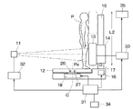
図1は被検者を回転させながら撮影を行うCT撮影状態時の側面から見た状態の構成図である。X線管球11の前方には、360゜回転可能な回転テーブル12上の被検者Pを介して例えば平面センサであるX線撮影部13が対向して配置されている。X線撮影部13はスライド部14を介して支柱15に取り付けられ、スライド部14は昇降駆動部16により昇降駆動され、X線撮影部13の下限位置は撮影部位置検知器17により検知されるようになっている。
The present invention will be described in detail based on the embodiment shown in FIGS.
FIG. 1 is a configuration diagram of a state viewed from the side in a CT imaging state in which imaging is performed while rotating a subject. In front of the
回転テーブル12は回転駆動部18に支持され、回転テーブル12上に、被検者Pが腰をかける椅子19、被検者Pが背中を密着させる背当て20、被検者Pの下肢PaをX線から保護する下肢ガード21が設けられている。
The rotary table 12 is supported by a
椅子19は回転テーブル12の回転軸Cの近傍に位置し、被検者Pは椅子19に座った状態で、背当て20に背中を密接させる。背当て20は鉛直方向に長く、その断面は被検者Pの背中が密着し易い円弧状とされ、背当て20には被検者Pを固定するためのベルト22やハンドル23が取り付けられている。また、背当て20の水平方向の位置は、被検者Pの撮影対象部位Pxが背当て20に密着した状態で、被検者Pの仮想体軸が回転テーブル12の回転軸Cとほぼ同軸となるように配置されている。
The
下肢ガード21は円形の回転テーブル12の外形に沿った円弧形状とされ、回転中に被検者Pの下肢Paが回転テーブル12の周囲の非回転部に接触することを防止している。
The
被検者支持部材である椅子19と背当て20は、第1の移動手段である椅子スライド部材24、背当てスライド部材25により、CT撮影位置から静止画撮影の妨げにならない撮影範囲外の位置に移動可能とされている。そして、椅子19、背当て20の位置は、椅子位置検知器26、背当て位置検知器27により検知されるようになっている。
The
このX線画像撮影装置の制御を行う制御部31の出力は、X線管球11に出力するX線発生装置32、昇降駆動部16、回転駆動部18、X線撮影部13の出力を取り込む画像取込部33に接続されている。また制御部31には、撮影部位置検知器17、椅子位置検知器26、背当て位置検知器27、フットスイッチ34の出力が接続されている。更に、画像取込部33の出力は画像処理部35に接続されている。
The output of the
スライド部14は第2の移動手段である昇降駆動部16により、X線撮影部13を支柱15に沿って鉛直方向に可変に昇降制御を行う。この昇降駆動部16による移動、停止は、技師によるフットスイッチ34からの操作を受け制御部31の指示により行われる。また、X線撮影部13の鉛直位置が、CT撮影の上下範囲L1にあるか否かは、撮影部位置検知器17により検出され、検知結果は制御部31に送信される。なお、上下範囲L1の下限位置は被検者支持部材の下肢ガード21が撮影領域に入り込まない位置に制限され、被検者Pの下肢Paとの接触を生じない高さに設定されている。
The
CT撮影を行うか静止画撮影を行うかの選択は、支持部材位置検知手段である椅子位置検知器26、背当て位置検知器27により検知され、その検知結果は制御部31に送信される。
The selection of whether to perform CT imaging or still image imaging is detected by a
CT撮影に際しては、制御部31は撮影要求信号により回転駆動部18を駆動して、回転テーブル12を回転制御する。所定の回転状態に達した時点で、X線管球11からのX線の曝射が始まりCT撮影が開始される。この状態では、制御部31はたとえフットスイッチ34が操作されても、X線撮影部13の昇降は行わず、X線撮影部13の位置を一定に保ち、これにより常に同じ位置の多方向からの画像が得られる。
At the time of CT imaging, the
この曝射に同期して、制御部31は画像取込部33を制御して、被検者Pを透過したX線をX線撮影部13により画像データとして取り込み、画像処理部35では被検者の360°の方向からの画像データを用いて三次元画像の断層像を得る。
In synchronization with this exposure, the
なお制御方法として、X線の照射に拘らず、回転テーブル12が回転中はX線撮影部13の昇降を行えないような制御としてもよい。
Note that the control method may be such that the
図2は椅子19、背当て20をCT撮影位置から静止画撮影状態の位置に変更し、図1の状態から回転テーブル12を右回りに90度回転した状態を上方から見た構成図、図3はこの状態を側面から見た構成図である。椅子19は椅子スライド部材24により、背当て20は背当てスライド部材25により回転テーブル12上で両側に移動し、被検者Pは身体をX線撮影部13に密接して撮影することが可能となる。
FIG. 2 is a configuration diagram in which the
X線管球11からのX線は、両側に退避した椅子19と背当て20の間を通過して、被検者Pに照射される。この場合に、上下方向に遮蔽物が存在しないため、被検者Pの頭部から下肢Paまで全身の任意の部位の撮影が、X線撮影部13の範囲L2において可能となる。
X-rays from the
静止画撮影では被検者Pの下肢Pa等の撮影を行うため、X線撮影部13を下方の位置に設定することがある。静止画撮影の後にCT撮影に切換える場合に、椅子19、背当て20をCT撮影形態に切換えても、X線撮影部13は静止画撮影位置にあることになる。この状態のまま、回転テーブル12を回転させると、衝突の可能性があり、本実施例ではこれを未然に防ぐ機構を有している。
In still image shooting, the
椅子19、背当て20がCT撮影の位置に変更されたことは、椅子位置検知器26、背当て位置検知器27により検知され、検知信号が制御部31に送られる。しかし、撮影部位置検知器17からの信号は、X線撮影部13がCT撮影位置にないと検知されている。この場合に、制御部31はたとえ技師により回転操作が行われても、回転テーブル12は停止状態を維持するように制御され、また図示しない表示部にX線撮影部13の上昇操作を促す警報が表示される。
The change of the
この状態では、制御部31はX線撮影部13の昇降移動の内、上昇側の操作のみ有効とする。技師がX線撮影部13をフットスイッチ34により上昇させると、X線撮影部13がCT撮影時の可動範囲L1に入った時点で、表示部のアラームが消える。また、アラーム表示と共に、CT撮影時の可動範囲L1の下端まで、X線撮影部13を自動的に上昇するように制御してもよい。これにより、静止画撮影とCT撮影との切換作業を行った場合に生ずる不具合を未然に防ぐことが可能となる。
In this state, the
図4はX線撮影部13の上下位置を調整する工程のフローチャート図である。技師はX線撮影部13の位置を調整する場合に、先ずフットスイッチ34の操作を行う(ステップS1)。制御部31は椅子位置検知器26、背当て位置検知器27からの信号により、椅子19、背当て20の被検者支持部材がCT撮影位置にあるか否かを判断する(ステップS2)。
FIG. 4 is a flowchart of a process for adjusting the vertical position of the
図1に示すようなCT撮影の状態の場合に、撮影部位置検知器17からの信号が範囲L1にある間は、制御部31はフットスイッチ34からの操作に従い昇降動作を許可する(ステップS3〜S6)。そして、所望の位置でフットスイッチ34から足を離し、昇降を停止させる。
In the case of CT imaging as shown in FIG. 1, while the signal from the imaging
ただし、移動によりCT範囲の限界位置に達するとその位置で停止し、それ以上の昇降は行わないように制御される(ステップS4〜S8)。これにより、CT撮影時は常にX線撮影部13がCT撮影範囲L1内に位置することになる。
However, when it reaches the limit position of the CT range due to the movement, it stops at that position and is controlled so as not to move up and down further (steps S4 to S8). Thus, the
また、図2、図3に示すように、被検者支持部材が一般静止画撮影の状態にある場合に、制御部31は撮影部位置検知器17からの信号に拘わらず、フットスイッチ34からの入力に従ってX線撮影部13の昇降が行えるように制御する(ステップS9〜S10)。これにより、一般静止画撮影時には図3に示す上下範囲L2までの広い範囲を移動することができ、被検者Pの頭部から下肢Paまで全身の撮影を可能とする。
As shown in FIGS. 2 and 3, when the subject support member is in a general still image shooting state, the
11 X線管球
12 回転テーブル
13 X線撮影部
14 スライド部
15 支柱
16 昇降駆動部
17 撮影部位置検知器
18 回転駆動部
19 椅子
20 背当て
21 下肢ガード
24 椅子スライド部材
25 背当てスライド部材
26 椅子位置検知器
27 背当て位置検知器
31 制御部
32 X線発生装置
33 画像取込部
34 フットスイッチ
35 画像処理部
P 被検者
DESCRIPTION OF
Claims (3)
被検者の撮影対象部位を固定する被検者支持部材と、
該被検者支持部材を前記CT撮影位置と撮影範囲外の位置との間で移動させる第1の移動手段と、
前記X線撮影部を鉛直方向に移動する第2の移動手段と、を有し、
前記被検者支持部材が前記CT撮影位置にある場合は、前記被検者支持部材が前記撮影範囲外の位置にある場合に対して、前記第2の移動手段が前記X線撮影部を鉛直方向に移動する範囲が短くなるように制限されることを特徴とするX線画像撮影装置。 An X-ray tube and an X-ray imaging unit are arranged opposite to each other with the subject interposed therebetween, and the subject is obtained by CT imaging that irradiates the subject on the rotary table while rotating the rotary table. In an X-ray imaging apparatus for imaging a tomographic image of
A subject support member for fixing the subject's imaging target site;
First moving means for moving the subject support member between the CT imaging position and a position outside the imaging range;
Second moving means for moving the X-ray imaging unit in the vertical direction;
When the subject support member is at the CT imaging position, the second moving means vertically moves the X-ray imaging unit when the subject support member is at a position outside the imaging range. An X-ray imaging apparatus characterized by being limited so that a range of movement in a direction is shortened.
Priority Applications (5)
| Application Number | Priority Date | Filing Date | Title |
|---|---|---|---|
| JP2007127539A JP5500766B2 (en) | 2007-05-14 | 2007-05-14 | X-ray imaging device |
| US12/119,215 US7729469B2 (en) | 2007-05-14 | 2008-05-12 | X-ray imaging apparatus |
| CN2008100969838A CN101305919B (en) | 2007-05-14 | 2008-05-14 | X-ray imaging apparatus |
| EP08156195A EP1992286B1 (en) | 2007-05-14 | 2008-05-14 | X-Ray imaging apparatus |
| AT08156195T ATE524110T1 (en) | 2007-05-14 | 2008-05-14 | X-RAY IMAGING DEVICE |
Applications Claiming Priority (1)
| Application Number | Priority Date | Filing Date | Title |
|---|---|---|---|
| JP2007127539A JP5500766B2 (en) | 2007-05-14 | 2007-05-14 | X-ray imaging device |
Publications (2)
| Publication Number | Publication Date |
|---|---|
| JP2008279150A JP2008279150A (en) | 2008-11-20 |
| JP5500766B2 true JP5500766B2 (en) | 2014-05-21 |
Family
ID=39816624
Family Applications (1)
| Application Number | Title | Priority Date | Filing Date |
|---|---|---|---|
| JP2007127539A Expired - Fee Related JP5500766B2 (en) | 2007-05-14 | 2007-05-14 | X-ray imaging device |
Country Status (5)
| Country | Link |
|---|---|
| US (1) | US7729469B2 (en) |
| EP (1) | EP1992286B1 (en) |
| JP (1) | JP5500766B2 (en) |
| CN (1) | CN101305919B (en) |
| AT (1) | ATE524110T1 (en) |
Families Citing this family (96)
| Publication number | Priority date | Publication date | Assignee | Title |
|---|---|---|---|---|
| CN101406398B (en) * | 2007-10-12 | 2013-06-19 | Ge医疗系统环球技术有限公司 | X ray imaging platform and X ray imaging device |
| US9056199B2 (en) | 2008-05-22 | 2015-06-16 | Vladimir Balakin | Charged particle treatment, rapid patient positioning apparatus and method of use thereof |
| US8089054B2 (en) | 2008-05-22 | 2012-01-03 | Vladimir Balakin | Charged particle beam acceleration and extraction method and apparatus used in conjunction with a charged particle cancer therapy system |
| US8718231B2 (en) | 2008-05-22 | 2014-05-06 | Vladimir Balakin | X-ray tomography method and apparatus used in conjunction with a charged particle cancer therapy system |
| US10684380B2 (en) | 2008-05-22 | 2020-06-16 | W. Davis Lee | Multiple scintillation detector array imaging apparatus and method of use thereof |
| US8901509B2 (en) | 2008-05-22 | 2014-12-02 | Vladimir Yegorovich Balakin | Multi-axis charged particle cancer therapy method and apparatus |
| US9095040B2 (en) | 2008-05-22 | 2015-07-28 | Vladimir Balakin | Charged particle beam acceleration and extraction method and apparatus used in conjunction with a charged particle cancer therapy system |
| US9168392B1 (en) | 2008-05-22 | 2015-10-27 | Vladimir Balakin | Charged particle cancer therapy system X-ray apparatus and method of use thereof |
| US8129699B2 (en) | 2008-05-22 | 2012-03-06 | Vladimir Balakin | Multi-field charged particle cancer therapy method and apparatus coordinated with patient respiration |
| US8309941B2 (en) * | 2008-05-22 | 2012-11-13 | Vladimir Balakin | Charged particle cancer therapy and patient breath monitoring method and apparatus |
| US10548551B2 (en) | 2008-05-22 | 2020-02-04 | W. Davis Lee | Depth resolved scintillation detector array imaging apparatus and method of use thereof |
| WO2009142545A2 (en) * | 2008-05-22 | 2009-11-26 | Vladimir Yegorovich Balakin | Charged particle cancer therapy patient positioning method and apparatus |
| US8487278B2 (en) | 2008-05-22 | 2013-07-16 | Vladimir Yegorovich Balakin | X-ray method and apparatus used in conjunction with a charged particle cancer therapy system |
| US9981147B2 (en) | 2008-05-22 | 2018-05-29 | W. Davis Lee | Ion beam extraction apparatus and method of use thereof |
| US8144832B2 (en) * | 2008-05-22 | 2012-03-27 | Vladimir Balakin | X-ray tomography method and apparatus used in conjunction with a charged particle cancer therapy system |
| US8129694B2 (en) | 2008-05-22 | 2012-03-06 | Vladimir Balakin | Negative ion beam source vacuum method and apparatus used in conjunction with a charged particle cancer therapy system |
| US7940894B2 (en) * | 2008-05-22 | 2011-05-10 | Vladimir Balakin | Elongated lifetime X-ray method and apparatus used in conjunction with a charged particle cancer therapy system |
| US9177751B2 (en) | 2008-05-22 | 2015-11-03 | Vladimir Balakin | Carbon ion beam injector apparatus and method of use thereof |
| US8519365B2 (en) * | 2008-05-22 | 2013-08-27 | Vladimir Balakin | Charged particle cancer therapy imaging method and apparatus |
| US9498649B2 (en) | 2008-05-22 | 2016-11-22 | Vladimir Balakin | Charged particle cancer therapy patient constraint apparatus and method of use thereof |
| AU2009249863B2 (en) | 2008-05-22 | 2013-12-12 | Vladimir Yegorovich Balakin | Multi-field charged particle cancer therapy method and apparatus |
| US9044600B2 (en) | 2008-05-22 | 2015-06-02 | Vladimir Balakin | Proton tomography apparatus and method of operation therefor |
| US8378321B2 (en) * | 2008-05-22 | 2013-02-19 | Vladimir Balakin | Charged particle cancer therapy and patient positioning method and apparatus |
| US7939809B2 (en) * | 2008-05-22 | 2011-05-10 | Vladimir Balakin | Charged particle beam extraction method and apparatus used in conjunction with a charged particle cancer therapy system |
| US8710462B2 (en) | 2008-05-22 | 2014-04-29 | Vladimir Balakin | Charged particle cancer therapy beam path control method and apparatus |
| NZ589387A (en) | 2008-05-22 | 2012-11-30 | Vladimir Yegorovich Balakin | Charged particle beam extraction method and apparatus used in conjunction with a charged particle cancer therapy system |
| US8188688B2 (en) | 2008-05-22 | 2012-05-29 | Vladimir Balakin | Magnetic field control method and apparatus used in conjunction with a charged particle cancer therapy system |
| US8288742B2 (en) | 2008-05-22 | 2012-10-16 | Vladimir Balakin | Charged particle cancer therapy patient positioning method and apparatus |
| US9910166B2 (en) | 2008-05-22 | 2018-03-06 | Stephen L. Spotts | Redundant charged particle state determination apparatus and method of use thereof |
| US8907309B2 (en) | 2009-04-17 | 2014-12-09 | Stephen L. Spotts | Treatment delivery control system and method of operation thereof |
| US9937362B2 (en) | 2008-05-22 | 2018-04-10 | W. Davis Lee | Dynamic energy control of a charged particle imaging/treatment apparatus and method of use thereof |
| US8198607B2 (en) | 2008-05-22 | 2012-06-12 | Vladimir Balakin | Tandem accelerator method and apparatus used in conjunction with a charged particle cancer therapy system |
| US8637833B2 (en) | 2008-05-22 | 2014-01-28 | Vladimir Balakin | Synchrotron power supply apparatus and method of use thereof |
| US8896239B2 (en) | 2008-05-22 | 2014-11-25 | Vladimir Yegorovich Balakin | Charged particle beam injection method and apparatus used in conjunction with a charged particle cancer therapy system |
| US9616252B2 (en) | 2008-05-22 | 2017-04-11 | Vladimir Balakin | Multi-field cancer therapy apparatus and method of use thereof |
| US9682254B2 (en) | 2008-05-22 | 2017-06-20 | Vladimir Balakin | Cancer surface searing apparatus and method of use thereof |
| US9155911B1 (en) | 2008-05-22 | 2015-10-13 | Vladimir Balakin | Ion source method and apparatus used in conjunction with a charged particle cancer therapy system |
| US8624528B2 (en) | 2008-05-22 | 2014-01-07 | Vladimir Balakin | Method and apparatus coordinating synchrotron acceleration periods with patient respiration periods |
| US8378311B2 (en) | 2008-05-22 | 2013-02-19 | Vladimir Balakin | Synchrotron power cycling apparatus and method of use thereof |
| US8975600B2 (en) | 2008-05-22 | 2015-03-10 | Vladimir Balakin | Treatment delivery control system and method of operation thereof |
| US9744380B2 (en) | 2008-05-22 | 2017-08-29 | Susan L. Michaud | Patient specific beam control assembly of a cancer therapy apparatus and method of use thereof |
| US9737733B2 (en) | 2008-05-22 | 2017-08-22 | W. Davis Lee | Charged particle state determination apparatus and method of use thereof |
| US9782140B2 (en) | 2008-05-22 | 2017-10-10 | Susan L. Michaud | Hybrid charged particle / X-ray-imaging / treatment apparatus and method of use thereof |
| US9737734B2 (en) | 2008-05-22 | 2017-08-22 | Susan L. Michaud | Charged particle translation slide control apparatus and method of use thereof |
| US9974978B2 (en) | 2008-05-22 | 2018-05-22 | W. Davis Lee | Scintillation array apparatus and method of use thereof |
| US8642978B2 (en) | 2008-05-22 | 2014-02-04 | Vladimir Balakin | Charged particle cancer therapy dose distribution method and apparatus |
| US10143854B2 (en) | 2008-05-22 | 2018-12-04 | Susan L. Michaud | Dual rotation charged particle imaging / treatment apparatus and method of use thereof |
| US9579525B2 (en) | 2008-05-22 | 2017-02-28 | Vladimir Balakin | Multi-axis charged particle cancer therapy method and apparatus |
| US8598543B2 (en) | 2008-05-22 | 2013-12-03 | Vladimir Balakin | Multi-axis/multi-field charged particle cancer therapy method and apparatus |
| US8178859B2 (en) | 2008-05-22 | 2012-05-15 | Vladimir Balakin | Proton beam positioning verification method and apparatus used in conjunction with a charged particle cancer therapy system |
| US8373145B2 (en) * | 2008-05-22 | 2013-02-12 | Vladimir Balakin | Charged particle cancer therapy system magnet control method and apparatus |
| US10092776B2 (en) | 2008-05-22 | 2018-10-09 | Susan L. Michaud | Integrated translation/rotation charged particle imaging/treatment apparatus and method of use thereof |
| US8399866B2 (en) | 2008-05-22 | 2013-03-19 | Vladimir Balakin | Charged particle extraction apparatus and method of use thereof |
| US10029122B2 (en) | 2008-05-22 | 2018-07-24 | Susan L. Michaud | Charged particle—patient motion control system apparatus and method of use thereof |
| WO2009142544A2 (en) | 2008-05-22 | 2009-11-26 | Vladimir Yegorovich Balakin | Charged particle cancer therapy beam path control method and apparatus |
| US8373146B2 (en) | 2008-05-22 | 2013-02-12 | Vladimir Balakin | RF accelerator method and apparatus used in conjunction with a charged particle cancer therapy system |
| US8373143B2 (en) | 2008-05-22 | 2013-02-12 | Vladimir Balakin | Patient immobilization and repositioning method and apparatus used in conjunction with charged particle cancer therapy |
| US10070831B2 (en) | 2008-05-22 | 2018-09-11 | James P. Bennett | Integrated cancer therapy—imaging apparatus and method of use thereof |
| US8093564B2 (en) * | 2008-05-22 | 2012-01-10 | Vladimir Balakin | Ion beam focusing lens method and apparatus used in conjunction with a charged particle cancer therapy system |
| US8436327B2 (en) | 2008-05-22 | 2013-05-07 | Vladimir Balakin | Multi-field charged particle cancer therapy method and apparatus |
| US8969834B2 (en) | 2008-05-22 | 2015-03-03 | Vladimir Balakin | Charged particle therapy patient constraint apparatus and method of use thereof |
| US8569717B2 (en) | 2008-05-22 | 2013-10-29 | Vladimir Balakin | Intensity modulated three-dimensional radiation scanning method and apparatus |
| US9855444B2 (en) | 2008-05-22 | 2018-01-02 | Scott Penfold | X-ray detector for proton transit detection apparatus and method of use thereof |
| US9737272B2 (en) | 2008-05-22 | 2017-08-22 | W. Davis Lee | Charged particle cancer therapy beam state determination apparatus and method of use thereof |
| US20090314960A1 (en) * | 2008-05-22 | 2009-12-24 | Vladimir Balakin | Patient positioning method and apparatus used in conjunction with a charged particle cancer therapy system |
| US8368038B2 (en) | 2008-05-22 | 2013-02-05 | Vladimir Balakin | Method and apparatus for intensity control of a charged particle beam extracted from a synchrotron |
| JP5450602B2 (en) | 2008-05-22 | 2014-03-26 | エゴロヴィチ バラキン、ウラジミール | Tumor treatment device for treating tumor using charged particles accelerated by synchrotron |
| US8625739B2 (en) | 2008-07-14 | 2014-01-07 | Vladimir Balakin | Charged particle cancer therapy x-ray method and apparatus |
| US8627822B2 (en) | 2008-07-14 | 2014-01-14 | Vladimir Balakin | Semi-vertical positioning method and apparatus used in conjunction with a charged particle cancer therapy system |
| MX2011009222A (en) | 2009-03-04 | 2011-11-02 | Protom Aozt | Multi-field charged particle cancer therapy method and apparatus. |
| US10555710B2 (en) | 2010-04-16 | 2020-02-11 | James P. Bennett | Simultaneous multi-axes imaging apparatus and method of use thereof |
| US10086214B2 (en) | 2010-04-16 | 2018-10-02 | Vladimir Balakin | Integrated tomography—cancer treatment apparatus and method of use thereof |
| US10179250B2 (en) | 2010-04-16 | 2019-01-15 | Nick Ruebel | Auto-updated and implemented radiation treatment plan apparatus and method of use thereof |
| US10556126B2 (en) | 2010-04-16 | 2020-02-11 | Mark R. Amato | Automated radiation treatment plan development apparatus and method of use thereof |
| US10751551B2 (en) | 2010-04-16 | 2020-08-25 | James P. Bennett | Integrated imaging-cancer treatment apparatus and method of use thereof |
| US10188877B2 (en) | 2010-04-16 | 2019-01-29 | W. Davis Lee | Fiducial marker/cancer imaging and treatment apparatus and method of use thereof |
| US10518109B2 (en) | 2010-04-16 | 2019-12-31 | Jillian Reno | Transformable charged particle beam path cancer therapy apparatus and method of use thereof |
| US9737731B2 (en) | 2010-04-16 | 2017-08-22 | Vladimir Balakin | Synchrotron energy control apparatus and method of use thereof |
| US10376717B2 (en) | 2010-04-16 | 2019-08-13 | James P. Bennett | Intervening object compensating automated radiation treatment plan development apparatus and method of use thereof |
| US10625097B2 (en) | 2010-04-16 | 2020-04-21 | Jillian Reno | Semi-automated cancer therapy treatment apparatus and method of use thereof |
| US10638988B2 (en) | 2010-04-16 | 2020-05-05 | Scott Penfold | Simultaneous/single patient position X-ray and proton imaging apparatus and method of use thereof |
| US10589128B2 (en) | 2010-04-16 | 2020-03-17 | Susan L. Michaud | Treatment beam path verification in a cancer therapy apparatus and method of use thereof |
| US11648420B2 (en) | 2010-04-16 | 2023-05-16 | Vladimir Balakin | Imaging assisted integrated tomography—cancer treatment apparatus and method of use thereof |
| US10349906B2 (en) | 2010-04-16 | 2019-07-16 | James P. Bennett | Multiplexed proton tomography imaging apparatus and method of use thereof |
| US8777485B2 (en) * | 2010-09-24 | 2014-07-15 | Varian Medical Systems, Inc. | Method and apparatus pertaining to computed tomography scanning using a calibration phantom |
| US8963112B1 (en) | 2011-05-25 | 2015-02-24 | Vladimir Balakin | Charged particle cancer therapy patient positioning method and apparatus |
| EP2659836A1 (en) * | 2012-05-02 | 2013-11-06 | General Electric Company | Solar powered wireless control device for medical imaging system |
| CN105188542B (en) * | 2012-10-08 | 2019-01-04 | 卡尔斯特里姆保健公司 | Limbs imaging device for cone-beam computed tomography |
| US8933651B2 (en) | 2012-11-16 | 2015-01-13 | Vladimir Balakin | Charged particle accelerator magnet apparatus and method of use thereof |
| CN104983437A (en) * | 2015-07-09 | 2015-10-21 | 冯艳 | Radiological shooting system |
| US9907981B2 (en) | 2016-03-07 | 2018-03-06 | Susan L. Michaud | Charged particle translation slide control apparatus and method of use thereof |
| US10118052B2 (en) * | 2016-05-27 | 2018-11-06 | Stephen L. Spotts | Charged particle cancer therapy installation system |
| US10037863B2 (en) | 2016-05-27 | 2018-07-31 | Mark R. Amato | Continuous ion beam kinetic energy dissipater apparatus and method of use thereof |
| JP6958851B2 (en) * | 2017-02-01 | 2021-11-02 | キヤノンメディカルシステムズ株式会社 | X-ray computed tomography equipment |
| JP6912769B2 (en) * | 2017-02-16 | 2021-08-04 | キヤノンメディカルシステムズ株式会社 | X-ray computed tomography equipment |
| TWI805388B (en) * | 2021-06-15 | 2023-06-11 | 采風智匯股份有限公司 | Limb positioning device used in x-ray image production |
Family Cites Families (11)
| Publication number | Priority date | Publication date | Assignee | Title |
|---|---|---|---|---|
| JPH0698885A (en) * | 1992-09-22 | 1994-04-12 | Toshiba Corp | Radiation tomographic apparatus |
| US5317617A (en) * | 1993-01-22 | 1994-05-31 | Lange Jon T | Method and apparatus for mounting the detector array of a CT scanner to a radiation therapy simulator |
| US6148058A (en) * | 1998-10-23 | 2000-11-14 | Analogic Corporation | System and method for real time measurement of detector offset in rotating-patient CT scanner |
| US6851851B2 (en) * | 1999-10-06 | 2005-02-08 | Hologic, Inc. | Digital flat panel x-ray receptor positioning in diagnostic radiology |
| DE10102324A1 (en) * | 2001-01-19 | 2002-07-25 | Philips Corp Intellectual Pty | X-ray device for tomosynthesis |
| US6470068B2 (en) * | 2001-01-19 | 2002-10-22 | Cheng Chin-An | X-ray computer tomography scanning system |
| EP2345370A3 (en) | 2002-03-19 | 2012-05-09 | Breakaway Imaging, Llc | Computer tomography with a detector following the movement of a pivotable x-ray source |
| JP3673791B2 (en) | 2002-05-22 | 2005-07-20 | キヤノン株式会社 | Radiographic apparatus and radiographic method |
| JP2005205082A (en) | 2004-01-26 | 2005-08-04 | Canon Inc | X-ray ct photography device |
| JP2006043193A (en) * | 2004-08-05 | 2006-02-16 | Canon Inc | Radiographic apparatus |
| JP4508789B2 (en) * | 2004-09-07 | 2010-07-21 | キヤノン株式会社 | X-ray equipment |
-
2007
- 2007-05-14 JP JP2007127539A patent/JP5500766B2/en not_active Expired - Fee Related
-
2008
- 2008-05-12 US US12/119,215 patent/US7729469B2/en not_active Expired - Fee Related
- 2008-05-14 CN CN2008100969838A patent/CN101305919B/en not_active Expired - Fee Related
- 2008-05-14 EP EP08156195A patent/EP1992286B1/en not_active Not-in-force
- 2008-05-14 AT AT08156195T patent/ATE524110T1/en not_active IP Right Cessation
Also Published As
| Publication number | Publication date |
|---|---|
| EP1992286A2 (en) | 2008-11-19 |
| ATE524110T1 (en) | 2011-09-15 |
| CN101305919A (en) | 2008-11-19 |
| US20090092223A1 (en) | 2009-04-09 |
| EP1992286B1 (en) | 2011-09-14 |
| EP1992286A3 (en) | 2008-12-31 |
| JP2008279150A (en) | 2008-11-20 |
| US7729469B2 (en) | 2010-06-01 |
| CN101305919B (en) | 2010-09-15 |
Similar Documents
| Publication | Publication Date | Title |
|---|---|---|
| JP5500766B2 (en) | X-ray imaging device | |
| US7596205B2 (en) | X-ray hybrid diagnosis system | |
| JP5752452B2 (en) | X-ray CT system | |
| JP4909730B2 (en) | X-ray diagnostic imaging apparatus and movement control method | |
| JP2003339686A (en) | X-ray radiographic apparatus | |
| WO2017073996A1 (en) | X-ray ct scanning apparatus and scanning method thereof | |
| JP4960212B2 (en) | X-ray diaphragm apparatus and X-ray imaging apparatus | |
| JP2015188611A (en) | digital panoramic X-ray imaging apparatus and dental CT apparatus | |
| JP4559312B2 (en) | Radiography equipment | |
| JP3725277B2 (en) | X-ray diagnostic system and X-ray CT scanner | |
| JP4084217B2 (en) | X-ray CT system | |
| JP2010155065A (en) | X-ray ct apparatus | |
| JP4574661B2 (en) | X-ray CT system | |
| JP2017164426A (en) | Radiography apparatus | |
| JP2007159598A (en) | X-ray ct apparatus | |
| JP2009112390A (en) | X-ray fluoroscope | |
| JP5959972B2 (en) | X-ray diagnostic equipment | |
| JPH0690949A (en) | X-ray diagnostic device | |
| US20210195121A1 (en) | Method and apparatus for changing image magnification power | |
| JP6818559B2 (en) | Medical diagnostic imaging equipment | |
| JP5676883B2 (en) | X-ray CT system | |
| JP6716196B2 (en) | X-ray equipment | |
| JP2008278923A (en) | X-ray radiographing apparatus | |
| JP5259949B2 (en) | X-ray CT system | |
| JP2005218462A (en) | X-ray diagnostic apparatus |
Legal Events
| Date | Code | Title | Description |
|---|---|---|---|
| RD01 | Notification of change of attorney |
Free format text: JAPANESE INTERMEDIATE CODE: A7421 Effective date: 20100218 |
|
| A621 | Written request for application examination |
Free format text: JAPANESE INTERMEDIATE CODE: A621 Effective date: 20100514 |
|
| RD01 | Notification of change of attorney |
Free format text: JAPANESE INTERMEDIATE CODE: A7421 Effective date: 20100630 |
|
| A977 | Report on retrieval |
Free format text: JAPANESE INTERMEDIATE CODE: A971007 Effective date: 20111208 |
|
| A131 | Notification of reasons for refusal |
Free format text: JAPANESE INTERMEDIATE CODE: A131 Effective date: 20111220 |
|
| A521 | Request for written amendment filed |
Free format text: JAPANESE INTERMEDIATE CODE: A523 Effective date: 20120220 |
|
| A131 | Notification of reasons for refusal |
Free format text: JAPANESE INTERMEDIATE CODE: A131 Effective date: 20120821 |
|
| A521 | Request for written amendment filed |
Free format text: JAPANESE INTERMEDIATE CODE: A523 Effective date: 20121019 |
|
| A131 | Notification of reasons for refusal |
Free format text: JAPANESE INTERMEDIATE CODE: A131 Effective date: 20130423 |
|
| A521 | Request for written amendment filed |
Free format text: JAPANESE INTERMEDIATE CODE: A523 Effective date: 20130624 |
|
| A131 | Notification of reasons for refusal |
Free format text: JAPANESE INTERMEDIATE CODE: A131 Effective date: 20131126 |
|
| A521 | Request for written amendment filed |
Free format text: JAPANESE INTERMEDIATE CODE: A523 Effective date: 20140127 |
|
| TRDD | Decision of grant or rejection written | ||
| A01 | Written decision to grant a patent or to grant a registration (utility model) |
Free format text: JAPANESE INTERMEDIATE CODE: A01 Effective date: 20140212 |
|
| A61 | First payment of annual fees (during grant procedure) |
Free format text: JAPANESE INTERMEDIATE CODE: A61 Effective date: 20140311 |
|
| LAPS | Cancellation because of no payment of annual fees |