JP5496047B2 - Image reproduction method, image reproduction apparatus, image reproduction program, imaging system, and reproduction system - Google Patents
Image reproduction method, image reproduction apparatus, image reproduction program, imaging system, and reproduction system Download PDFInfo
- Publication number
- JP5496047B2 JP5496047B2 JP2010227774A JP2010227774A JP5496047B2 JP 5496047 B2 JP5496047 B2 JP 5496047B2 JP 2010227774 A JP2010227774 A JP 2010227774A JP 2010227774 A JP2010227774 A JP 2010227774A JP 5496047 B2 JP5496047 B2 JP 5496047B2
- Authority
- JP
- Japan
- Prior art keywords
- image
- picture
- decoding
- memory
- reference image
- Prior art date
- Legal status (The legal status is an assumption and is not a legal conclusion. Google has not performed a legal analysis and makes no representation as to the accuracy of the status listed.)
- Active
Links
- 238000000034 method Methods 0.000 title claims description 109
- 238000003384 imaging method Methods 0.000 title claims description 12
- 230000015654 memory Effects 0.000 claims description 197
- 238000007906 compression Methods 0.000 claims description 81
- 230000006835 compression Effects 0.000 claims description 80
- 238000012545 processing Methods 0.000 claims description 42
- 230000008569 process Effects 0.000 claims description 41
- 230000002123 temporal effect Effects 0.000 claims description 16
- 238000006243 chemical reaction Methods 0.000 claims description 13
- 230000006866 deterioration Effects 0.000 claims description 13
- 238000004458 analytical method Methods 0.000 claims description 10
- 239000013598 vector Substances 0.000 claims description 9
- 230000003287 optical effect Effects 0.000 claims description 7
- 230000015556 catabolic process Effects 0.000 claims description 5
- 238000006731 degradation reaction Methods 0.000 claims description 5
- 230000006837 decompression Effects 0.000 claims description 4
- 238000013139 quantization Methods 0.000 description 14
- 230000009467 reduction Effects 0.000 description 10
- 230000014509 gene expression Effects 0.000 description 9
- 238000012546 transfer Methods 0.000 description 9
- 238000010586 diagram Methods 0.000 description 6
- 238000009825 accumulation Methods 0.000 description 5
- 230000002427 irreversible effect Effects 0.000 description 4
- 230000002457 bidirectional effect Effects 0.000 description 3
- 238000005516 engineering process Methods 0.000 description 2
- 230000008929 regeneration Effects 0.000 description 2
- 238000011069 regeneration method Methods 0.000 description 2
- 230000009466 transformation Effects 0.000 description 2
- 238000004364 calculation method Methods 0.000 description 1
- 230000008859 change Effects 0.000 description 1
- 238000004891 communication Methods 0.000 description 1
- 230000000694 effects Effects 0.000 description 1
- 238000001914 filtration Methods 0.000 description 1
- 238000007429 general method Methods 0.000 description 1
- 239000004973 liquid crystal related substance Substances 0.000 description 1
- 238000011160 research Methods 0.000 description 1
- 230000007480 spreading Effects 0.000 description 1
Images


Classifications
-
- H—ELECTRICITY
- H04—ELECTRIC COMMUNICATION TECHNIQUE
- H04N—PICTORIAL COMMUNICATION, e.g. TELEVISION
- H04N19/00—Methods or arrangements for coding, decoding, compressing or decompressing digital video signals
- H04N19/50—Methods or arrangements for coding, decoding, compressing or decompressing digital video signals using predictive coding
-
- H—ELECTRICITY
- H04—ELECTRIC COMMUNICATION TECHNIQUE
- H04N—PICTORIAL COMMUNICATION, e.g. TELEVISION
- H04N19/00—Methods or arrangements for coding, decoding, compressing or decompressing digital video signals
- H04N19/10—Methods or arrangements for coding, decoding, compressing or decompressing digital video signals using adaptive coding
- H04N19/102—Methods or arrangements for coding, decoding, compressing or decompressing digital video signals using adaptive coding characterised by the element, parameter or selection affected or controlled by the adaptive coding
- H04N19/103—Selection of coding mode or of prediction mode
-
- H—ELECTRICITY
- H04—ELECTRIC COMMUNICATION TECHNIQUE
- H04N—PICTORIAL COMMUNICATION, e.g. TELEVISION
- H04N19/00—Methods or arrangements for coding, decoding, compressing or decompressing digital video signals
- H04N19/10—Methods or arrangements for coding, decoding, compressing or decompressing digital video signals using adaptive coding
- H04N19/134—Methods or arrangements for coding, decoding, compressing or decompressing digital video signals using adaptive coding characterised by the element, parameter or criterion affecting or controlling the adaptive coding
- H04N19/156—Availability of hardware or computational resources, e.g. encoding based on power-saving criteria
-
- H—ELECTRICITY
- H04—ELECTRIC COMMUNICATION TECHNIQUE
- H04N—PICTORIAL COMMUNICATION, e.g. TELEVISION
- H04N19/00—Methods or arrangements for coding, decoding, compressing or decompressing digital video signals
- H04N19/10—Methods or arrangements for coding, decoding, compressing or decompressing digital video signals using adaptive coding
- H04N19/169—Methods or arrangements for coding, decoding, compressing or decompressing digital video signals using adaptive coding characterised by the coding unit, i.e. the structural portion or semantic portion of the video signal being the object or the subject of the adaptive coding
- H04N19/17—Methods or arrangements for coding, decoding, compressing or decompressing digital video signals using adaptive coding characterised by the coding unit, i.e. the structural portion or semantic portion of the video signal being the object or the subject of the adaptive coding the unit being an image region, e.g. an object
- H04N19/172—Methods or arrangements for coding, decoding, compressing or decompressing digital video signals using adaptive coding characterised by the coding unit, i.e. the structural portion or semantic portion of the video signal being the object or the subject of the adaptive coding the unit being an image region, e.g. an object the region being a picture, frame or field
-
- H—ELECTRICITY
- H04—ELECTRIC COMMUNICATION TECHNIQUE
- H04N—PICTORIAL COMMUNICATION, e.g. TELEVISION
- H04N19/00—Methods or arrangements for coding, decoding, compressing or decompressing digital video signals
- H04N19/10—Methods or arrangements for coding, decoding, compressing or decompressing digital video signals using adaptive coding
- H04N19/169—Methods or arrangements for coding, decoding, compressing or decompressing digital video signals using adaptive coding characterised by the coding unit, i.e. the structural portion or semantic portion of the video signal being the object or the subject of the adaptive coding
- H04N19/186—Methods or arrangements for coding, decoding, compressing or decompressing digital video signals using adaptive coding characterised by the coding unit, i.e. the structural portion or semantic portion of the video signal being the object or the subject of the adaptive coding the unit being a colour or a chrominance component
-
- H—ELECTRICITY
- H04—ELECTRIC COMMUNICATION TECHNIQUE
- H04N—PICTORIAL COMMUNICATION, e.g. TELEVISION
- H04N19/00—Methods or arrangements for coding, decoding, compressing or decompressing digital video signals
- H04N19/10—Methods or arrangements for coding, decoding, compressing or decompressing digital video signals using adaptive coding
- H04N19/189—Methods or arrangements for coding, decoding, compressing or decompressing digital video signals using adaptive coding characterised by the adaptation method, adaptation tool or adaptation type used for the adaptive coding
- H04N19/192—Methods or arrangements for coding, decoding, compressing or decompressing digital video signals using adaptive coding characterised by the adaptation method, adaptation tool or adaptation type used for the adaptive coding the adaptation method, adaptation tool or adaptation type being iterative or recursive
- H04N19/194—Methods or arrangements for coding, decoding, compressing or decompressing digital video signals using adaptive coding characterised by the adaptation method, adaptation tool or adaptation type used for the adaptive coding the adaptation method, adaptation tool or adaptation type being iterative or recursive involving only two passes
-
- H—ELECTRICITY
- H04—ELECTRIC COMMUNICATION TECHNIQUE
- H04N—PICTORIAL COMMUNICATION, e.g. TELEVISION
- H04N19/00—Methods or arrangements for coding, decoding, compressing or decompressing digital video signals
- H04N19/42—Methods or arrangements for coding, decoding, compressing or decompressing digital video signals characterised by implementation details or hardware specially adapted for video compression or decompression, e.g. dedicated software implementation
- H04N19/43—Hardware specially adapted for motion estimation or compensation
- H04N19/433—Hardware specially adapted for motion estimation or compensation characterised by techniques for memory access
-
- H—ELECTRICITY
- H04—ELECTRIC COMMUNICATION TECHNIQUE
- H04N—PICTORIAL COMMUNICATION, e.g. TELEVISION
- H04N19/00—Methods or arrangements for coding, decoding, compressing or decompressing digital video signals
- H04N19/44—Decoders specially adapted therefor, e.g. video decoders which are asymmetric with respect to the encoder
Landscapes
- Engineering & Computer Science (AREA)
- Multimedia (AREA)
- Signal Processing (AREA)
- Computing Systems (AREA)
- Theoretical Computer Science (AREA)
- Compression Or Coding Systems Of Tv Signals (AREA)
Description
本発明は、画像再生技術に関し、特に、時間方向の冗長性を削減することによって情報量の圧縮を行う画面間予測符号化を用いて符号化された動画像ストリームをデコードして再生する画像再生に関するものである。 The present invention relates to an image reproduction technique, and in particular, image reproduction that decodes and reproduces a moving image stream encoded using inter-frame predictive encoding that compresses the amount of information by reducing redundancy in the time direction. It is about.
近年、MPEG−2(ISO/IEC 13818-2)をはじめ、MPEG−4(ISO/IEC 14496-2)やH.264(ISO/IEC 14496-10)といった動画像符号化技術が盛んに研究され、コンピュータ、通信、民生用AV機器および放送などの様々な分野で応用されている。 In recent years, MPEG-2 (ISO / IEC 13818-2), MPEG-4 (ISO / IEC 14496-2) and H.264 have been developed. Video coding technology such as H.264 (ISO / IEC 14496-10) has been actively researched and applied in various fields such as computers, communications, consumer AV equipment and broadcasting.
これらの動画像符号化技術では、同一画面上の空間方向の冗長性を削減する画面内予測符号化と、すでに符号化・復号化された前後のピクチャ(参照画像)を参照して予測画像を生成し、得られた予測画像と符号化対象ピクチャとの差分値に対して符号化を行うことで時間的な冗長性を削減する画面間予測符号化との2種類の符号化方式を用いることによって、情報量の圧縮を行っている。画面間予測符号化された動画像ストリームをデコードして再生するためには、予測画像を生成するために参照ピクチャを一時的に記憶しておくための参照画像メモリが必要となる。この参照画像メモリとしては、一般的にDRAMのような外部メモリ、またはシステムLSIに内蔵される混載メモリが用いられ、予測画像を生成するために、この参照画像メモリに対してメモリアクセスが発生する。 In these moving image coding technologies, intra prediction prediction for reducing redundancy in the spatial direction on the same screen and prediction pictures by referring to previous and subsequent pictures (reference pictures) that have already been encoded and decoded. Use two types of encoding schemes: inter-frame prediction encoding that reduces temporal redundancy by encoding the difference value between the generated predicted image and the encoding target picture. Thus, the amount of information is compressed. In order to decode and reproduce a video stream that has been inter-screen predictively encoded, a reference picture memory for temporarily storing a reference picture is required to generate a predicted picture. As the reference image memory, an external memory such as a DRAM or a mixed memory built in the system LSI is generally used, and memory access is generated to the reference image memory in order to generate a predicted image. .
一方、近年では、大画面のプラズマディスプレイや液晶テレビをはじめとした高精細フラットパネルディスプレイが急速に市場に普及していく中、高精細なHDTV動画記録可能なデジタルビデオカメラやデジタルスチルカメラ等の民生用小型カメラが、数万円程度のリーズナブルな価格で購入できるようになってきている。このようなカメラで撮影された動画像ストリームをデコードして再生するためには、参照画像メモリへの頻繁なメモリアクセス(トラフィック)が発生しても問題なく正常に動画像ストリームをデコードできるよう、高帯域なメモリバンド幅を有する参照画像メモリを搭載する必要がある。 On the other hand, in recent years, as high-definition flat panel displays such as large-screen plasma displays and liquid crystal televisions are rapidly spreading in the market, high-definition HDTV video recording digital video cameras, digital still cameras, etc. Small consumer cameras can be purchased at a reasonable price of around tens of thousands of yen. In order to decode and play back a moving image stream shot with such a camera, even if frequent memory access (traffic) to the reference image memory occurs, the moving image stream can be decoded normally without any problem. It is necessary to mount a reference image memory having a high bandwidth memory bandwidth.
高帯域なメモリバンド幅を確保するためには、例えば、32bitのデータビット幅を有するDRAMを複数個用いたり、あるいはLPDDR2(Low Power Double Data Rate 2)−SDRAMのような高速な動作周波数でも動作可能な高性能なDRAMを用いる必要がある。ところがいずれの場合も、実装コストが高くなったり消費電力が大きくなったりするため、低コスト化と省電力化が困難という課題があった。特に、小型バッテリーで動作するデジタルビデオカメラやデジタルスチルカメラ等の民生用小型カメラにおいては、低コスト・省電力に対するニーズは非常に高く、このため、動画像ストリームのデコードにおける低コスト・省電力化に関する研究が盛んに行われている。 In order to secure a high bandwidth memory bandwidth, for example, a plurality of DRAMs having a data bit width of 32 bits are used, or an operation is performed at a high operating frequency such as LPDDR2 (Low Power Double Data Rate 2) -SDRAM. It is necessary to use a high-performance DRAM capable. However, in either case, there is a problem that it is difficult to reduce the cost and save power because the mounting cost increases and the power consumption increases. In particular, small consumer cameras such as digital video cameras and digital still cameras that operate with a small battery have a very high need for low cost and low power consumption. Therefore, low cost and low power consumption in decoding video streams There is a lot of research on this.
次に、動画像ストリームをデコードして再生する一般的な方法について、以下に説明する。 Next, a general method for decoding and reproducing a moving image stream will be described below.
図11は動画像ストリームを入力し、順次デコードして再生画像を出力する一般的な画像再生装置を簡単に示す図である。入力端子2から再生対象となる動画像ストリームが入力され、デコーダ603においてはピクチャ層、スライス層、マクロブロック層のデコードがピクチャ毎に順次行われる。デコードされたピクチャは出力端子13から図示していない表示制御部に出力される。また、参照画像として残す必要があるピクチャ(例えば、I/Pピクチャ)は、参照画像メモリ5に書き込まれ一時的に記憶される。参照画像メモリ5を、例えば、32bitのデータバスを有するメモリで構成した場合には、4画素(8bit×4画素=32bit)を一つのアドレスに記憶するような方式で書き込まれ、64bitのデータバスを有するメモリで構成した場合には、8画素(8bit×8画素=64bit)を一つのアドレスに記憶するような形式で書き込まれる。
FIG. 11 is a diagram simply showing a general image reproducing apparatus that inputs a moving image stream, sequentially decodes and outputs a reproduced image. A moving image stream to be reproduced is input from the
また、画面間予測符号化されているピクチャ(例えば、P/Bピクチャ)をデコードする場合は、参照画像メモリ5に記憶されている参照画像が順次読み出されて予測画像が生成され、デコードされた差分値と加算されて、出力端子13から図示していない表示制御部に出力される。
In addition, when decoding a picture (for example, a P / B picture) that has been subjected to inter-picture prediction encoding, reference pictures stored in the
参照画像メモリ5に上記のような形式で一時的に記憶されている参照画像を読み出す場合は、デコード対象となるマクロブロックの画面内の位置と動きベクトル値とに基づいて参照画像の2次元空間内の読み出し先頭アドレスが算出され、参照画像メモリ5の読み出しアドレス(32bitのデータバスを有するメモリの場合は4画素単位のアドレス)に変換される。
When a reference image temporarily stored in the above-described format in the
図13(1)(2)はその一例を示す。算出された参照画像の2次元空間内の読み出し先頭アドレスが参照画像メモリ5の読み出しアドレスの境界と一致する場合(図13(1))は、16×16画素の予測画像を生成するための読み出し時に発生するリードトラフィックは256バイト(4画素単位のアドレスで64アドレス分)となり、読み出しにおける無効画素を含んだ転送は一切発生しない。一方、算出された参照画像の2次元空間内の読み出し先頭アドレスが参照画像メモリ5の読み出しアドレスの境界と一致しない場合(図13(2))は、16×16画素の予測画像を生成するための読み出し時に発生するリードトラフィックは320バイト(4画素単位のアドレスで80アドレス分)となり、読み出しにおける無効画素を含んだ転送が多く発生し、読み出しにおけるオーバーヘッドが大きくなる。 FIGS. 13 (1) and (2) show an example. When the calculated read start address in the two-dimensional space of the reference image matches the boundary of the read address of the reference image memory 5 (FIG. 13 (1)), read for generating a predicted image of 16 × 16 pixels. The read traffic sometimes generated is 256 bytes (64 addresses in units of 4 pixels), and no transfer including invalid pixels in reading occurs. On the other hand, when the calculated read start address in the two-dimensional space of the reference image does not coincide with the read address boundary of the reference image memory 5 (FIG. 13 (2)), a predicted image of 16 × 16 pixels is generated. The read traffic generated at the time of reading becomes 320 bytes (80 addresses in units of 4 pixels), and many transfers including invalid pixels in reading occur, and the overhead in reading increases.
また、MPEG−2の場合は、この予測画像を生成する際の動き補償の単位は16×16画素で構成される比較的大きなブロック単位であるため、リード時に発生するオーバーヘッドも大きな問題にはならない。ところが、MPEG−4では動き補償の単位として16×16画素だけではなく、8×8画素単位もサポートされ、さらに、H.264では動き補償の精度をより一層高める目的で、図12に示すように、16×16,16×8,8×16,8×8,8×4,4×8,4×4画素といった、より細かいブロック単位での動き補償がサポートされており、読み出しにおけるオーバーヘッドもさらに大きくなる。 In the case of MPEG-2, since the unit of motion compensation when generating the predicted image is a relatively large block unit composed of 16 × 16 pixels, the overhead generated at the time of reading is not a big problem. . However, MPEG-4 supports not only 16 × 16 pixels but also 8 × 8 pixel units as motion compensation units. In order to further improve the accuracy of motion compensation in H.264, as shown in FIG. 12, 16 × 16, 16 × 8, 8 × 16, 8 × 8, 8 × 4, 4 × 8, 4 × 4 pixels, etc. Finer motion compensation in units of blocks is supported, and the overhead in reading is further increased.
具体的には、例えば、動き補償のサイズが4×4画素の場合、図13(3)(4)に示すように、算出された参照画像の2次元空間内の読み出し先頭アドレスが参照画像メモリ5の読み出しアドレスの境界と一致する場合(図13(3))は、4×4画素の予測画像を生成するための読み出し時に発生するリードトラフィックは16バイト(4画素単位のアドレスで4アドレス分)となり、読み出しにおける無効画素を含んだ転送は一切発生しない。一方、算出された参照画像の2次元空間内の読み出し先頭アドレスが参照画像メモリ5の読み出しアドレスの境界と一致しない場合(図13(4))は、4×4画素の予測画像を生成するための読み出し時に発生するリードトラフィックは32バイト(4画素単位のアドレスで8アドレス分)となり、読み出しにおける無効画素を含んだ転送が多く発生し、読み出しにおけるオーバーヘッドも16×16画素単位での動き補償と比較して、大きくなる。 Specifically, for example, when the size of motion compensation is 4 × 4 pixels, as shown in FIGS. 13 (3) and (4), the read start address in the two-dimensional space of the calculated reference image is the reference image memory. When the boundary of 5 read addresses coincides (FIG. 13 (3)), the read traffic generated at the time of reading for generating a predicted image of 4 × 4 pixels is 16 bytes (4 addresses in units of 4 pixels). Thus, no transfer including invalid pixels in readout occurs. On the other hand, when the read start address of the calculated reference image in the two-dimensional space does not coincide with the read address boundary of the reference image memory 5 (FIG. 13 (4)), a predicted image of 4 × 4 pixels is generated. The read traffic generated at the time of reading is 32 bytes (equivalent to 8 addresses in units of 4 pixels), many transfers including invalid pixels in reading occur, and the overhead in reading is also motion compensation in units of 16 × 16 pixels. In comparison, it becomes larger.
すなわち、動画像ストリームをデコードする場合は、参照画像メモリ5内の動きベクトルで指し示される任意の画素位置からのブロック単位でのランダムアクセスが必要となるため、画素位置によっては参照画像メモリ5を効率良くアクセスできず、メモリアクセス時のオーバーヘッドが多くなる。また、予測画像生成のための動き補償のサイズが小さくなればなる程、メモリアクセス(リードアクセス)時のオーバーヘッドがより一層多くなる。
That is, when decoding a moving image stream, random access in units of blocks from an arbitrary pixel position indicated by a motion vector in the
参照画像メモリの容量やデータバスのビット幅、動作周波数等の仕様は、デコーダがサポートする動画ストリームの解像度やフレームレート(MPEG−2やH.264等の規格ではレベルで規定)等によって決定される事項である。そして、この参照画像メモリの仕様は、規格の範囲内において発生する可能性のあるワーストケースを想定した上で決定される。このため、HDTV動画に対応した民生用小型カメラ等では、高性能な参照画像メモリを備える必要があり、よって、低コスト化と省電力化を実現することが困難であった。 Specifications such as the capacity of the reference image memory, the bit width of the data bus, and the operating frequency are determined by the resolution and frame rate of the video stream supported by the decoder (specified by the level in standards such as MPEG-2 and H.264). It is a matter. The specification of the reference image memory is determined on the assumption of the worst case that may occur within the standard range. For this reason, it is necessary to provide a high-performance reference image memory in a consumer-use compact camera or the like that supports HDTV video, and thus it has been difficult to realize cost reduction and power saving.
なお、ここで述べるワーストケースとは、具体的には、動画像ストリーム内の画面間予測符号化されているピクチャが、以下のように符号化されている場合である。 Note that the worst case described here is specifically a case where a picture that has been subjected to inter-picture prediction encoding in a moving picture stream is encoded as follows.
・予測画像を生成するために発生する参照画像メモリアクセスが、ピクチャ内のすべてのマクロブロックにおいて、無効転送画素を含んだオーバーヘッドの最も大きい転送である。 The reference image memory access that occurs to generate the predicted image is the transfer with the highest overhead including invalid transfer pixels in all macroblocks in the picture.
・マクロブロックの動き補償サイズが、ピクチャ内のすべてのマクロブロックにおいて、最小サイズである。(例えば、H.264の場合、4×4画素)
・前方予測/後方予測/双方向予測が可能なBピクチャについては、ピクチャ内のすべてのマクロブロックにおいて、双方向予測を用いて符号化されている。
The motion compensation size of the macroblock is the minimum size for all macroblocks in the picture. (For example, in the case of H.264, 4 × 4 pixels)
A B picture capable of forward prediction / backward prediction / bidirectional prediction is encoded using bidirectional prediction in all macroblocks in the picture.
上記のような課題を解決するメモリバンド幅削減に関する技術が、特許文献1〜4に開示されている。
Techniques relating to memory bandwidth reduction that solve the above-described problems are disclosed in
特許文献1および2によると、デコードされた画像はフィルタ処理によって縮小されて参照画像メモリに記憶され、参照画像メモリから読み出された縮小画像をフィルタ処理によって拡大した画像が参照画像として用いられる。
According to
特許文献3によると、デコードされた画像をアダマール変換および量子化により圧縮した画像が参照画像メモリに記憶され、参照画像メモリから読み出された圧縮画像を逆量子化および逆アダマール変換によって伸張した画像が参照画像として用いられる。
According to
特許文献4によると、デコードされた画像を参照画像メモリに記憶する際に、縮小や圧縮などの非可逆な変換処理を施すことによって発生する圧縮歪を、以降のピクチャをデコードする際に時間的に累積しないよう、適応的に制御する。
According to
特許文献1,2および3に記載されたメモリバンド幅削減方法では、いずれの場合も、デコードされた画像に対してフィルタリングやアダマール変換・量子化といった非可逆変換の処理が行われて参照画像が生成されるため、この非可逆変換によって発生した不要な圧縮歪が参照画像に重畳されてしまう。画面間予測符号化を行うMPEG−2やH.264のような動画像符号化方式では、参照画像の歪は次のデコード画像に重畳され、歪の重畳されたデコード画像はさらに次の参照画像として用いられるため、デコード時に発生する圧縮歪は時間的に累積される。
In any of the memory bandwidth reduction methods described in
そして、特許文献1,2および3の場合、高解像度画像や高フレームレート画像などメモリアクセス量が多く発生する動画像ストリームに関しては、動画像ストリームを実際にデコードした際に発生するメモリアクセス量の大小に関わらず、予め上記のようなワーストケースを想定した上で参照画像メモリの許容メモリバンド幅を超えると判断された場合は、常に、この参照画像に非可逆変換を施してメモリアクセスの削減を図る。このため、この非可逆変換によって発生したノイズも常に時間的に累積されることになるので、再生されたデコード画像において大きなノイズとして視覚的にも発見されやすくなる、といった課題がある。
In the case of
特許文献4のメモリアクセス削減方法は、上記のようなデコード処理における圧縮歪の時間的な累積を抑制するために、圧縮した参照画像と非圧縮の参照画像の2種類の参照画像を参照画像メモリに記憶し、Pピクチャなど圧縮歪が時間的に累積されるピクチャの場合には非圧縮の参照画像を用いてデコードし、Bピクチャなど圧縮歪が時間的に累積されないピクチャの場合には圧縮した参照画像を用いてデコードすることによって、メモリバンド幅削減を図る技術である。しかし、圧縮した参照画像と非圧縮の参照画像の2種類の参照画像を参照画像メモリに記憶する必要があり、より一層大容量のメモリを必要とする、といった課題がある。
The memory access reduction method disclosed in
また、圧縮した参照画像と非圧縮の参照画像の2種類の参照画像を参照画像メモリに書き込む必要が発生するため、圧縮した参照画像を参照してデコードする場合のリードアクセスが削減できる一方、逆に、圧縮した参照画像も参照画像メモリに別途書き込むためのライトアクセスが増加し、結果として、大きなメモリバンド幅削減には繋がらない、といった課題がある。特に、Pピクチャをデコードする場合は、圧縮歪が時間的に累積されないように非圧縮の参照画像を参照画像メモリからリードする必要がある上に、以降のピクチャのデコードに必要となる参照画像として、圧縮した画像と非圧縮の画像の両方を参照画像メモリにライトする必要が発生するため、特許文献4の技術を導入しない場合よりも必要となるメモリバンド幅は逆に増加する。
In addition, since it is necessary to write two types of reference images, a compressed reference image and an uncompressed reference image, to the reference image memory, read access can be reduced when the compressed reference image is referenced and decoded. In addition, there is a problem that write access for separately writing a compressed reference image to the reference image memory increases, and as a result, it does not lead to a large memory bandwidth reduction. In particular, when decoding a P picture, it is necessary to read an uncompressed reference image from the reference image memory so that the compression distortion is not accumulated over time, and as a reference image necessary for decoding the subsequent pictures. Since it is necessary to write both the compressed image and the non-compressed image to the reference image memory, the required memory bandwidth is increased compared to the case where the technique of
また、特許文献4には、圧縮した参照画像を用いて予測画像を生成する方式を双方向予測されたマクロブロックに限定して適用することで、参照画像を圧縮した際に発生する歪が低減されると記載されているが、これは例えば、前方予測用ピクチャにおける圧縮の歪がプラス側、後方予測用ピクチャにおける圧縮の歪がマイナス側に発生している場合に言えることである。前方予測用ピクチャおよび後方予測用ピクチャにおける圧縮の歪が両方ともプラス側あるいはマイナス側に発生している場合は、参照画像を圧縮した際に発生する歪が低減されることはなく、Bピクチャをデコードして再生する場合にもノイズとして視覚的にも確認される場合がある。
Further, in
上記のような課題を解決するため、本発明は、低コスト・省電力で、デコード時に発生する圧縮歪の時間的な累積を抑制可能な画像再生技術を提供することを目的としている。 In order to solve the above-described problems, an object of the present invention is to provide an image reproduction technique capable of suppressing temporal accumulation of compression distortion generated at the time of decoding at low cost and power saving.
本発明の一態様は、画面間予測符号化された動画像ストリームを参照画像メモリにアクセスしながらデコードする画像再生方法として、前記参照画像メモリに対するトラフィックをピクチャ単位で見積もるために、前記動画像ストリームをピクチャ単位でデコードする第1のデコードステップと、再生画像を生成するために、前記動画像ストリームをピクチャ単位でデコードする第2のデコードステップとを備え、前記第2のデコードステップにおいて、デコード対象ピクチャが、デコード後に参照画像として前記参照画像メモリに格納すべきものであるとき、前記第1のデコードステップにおいて見積もられた、当該デコード対象ピクチャを参照するピクチャに係るトラフィックを基にして、当該デコード対象ピクチャを前記参照画像メモリに格納する際の圧縮態様を設定するものである。 According to an aspect of the present invention, there is provided an image reproduction method for decoding a video stream that has been inter prediction encoded while accessing a reference picture memory, in order to estimate traffic to the reference picture memory in units of pictures. A first decoding step for decoding the video stream in units of pictures and a second decoding step for decoding the moving picture stream in units of pictures in order to generate a playback image. In the second decoding step, When a picture is to be stored in the reference picture memory as a reference picture after decoding, the decoding is performed based on traffic related to the picture that refers to the picture to be decoded, estimated in the first decoding step. The reference picture memo is the target picture. It is to set the compression mode when storing the.
この態様によると、第1のデコードステップにおいて、動画像ストリームの各ピクチャについて、参照画像メモリに対するトラフィックが見積もられる。そして、再生画像を生成するための第2のデコードステップにおいて、デコード対象ピクチャがいわゆる参照ピクチャであるとき、第1のデコードステップにおいて見積もられた、当該デコード対象ピクチャを参照するピクチャに係るトラフィックを基にして、デコード対象ピクチャを参照画像メモリに格納する際の圧縮態様が設定される。すなわち、参照画像を格納する際の圧縮態様が、事前に解析したメモリアクセスにおけるトラフィックに基づいて設定されるので、例えば必要性の低い圧縮処理を回避することができ、よって、デコード時に発生する圧縮歪の時間的な累積を従来よりも抑制することができる。しかも、必要以上の高性能なメモリを搭載する必要がなく、例えば、外部メモリの個数を不必要に増加させたり、メモリをより高速な動作周波数で動作させたりせずに済む。 According to this aspect, in the first decoding step, traffic to the reference image memory is estimated for each picture of the moving image stream. Then, when the decoding target picture is a so-called reference picture in the second decoding step for generating the reproduced image, the traffic related to the picture that refers to the decoding target picture estimated in the first decoding step is Based on this, the compression mode when the decoding target picture is stored in the reference image memory is set. That is, since the compression mode for storing the reference image is set based on the memory access traffic analyzed in advance, it is possible to avoid, for example, a compression process that is less necessary, and thus compression that occurs at the time of decoding. The accumulation of distortion over time can be suppressed more than in the past. In addition, it is not necessary to mount an unnecessarily high-performance memory. For example, it is not necessary to unnecessarily increase the number of external memories or to operate the memory at a higher operating frequency.
本発明によると、参照画像を格納する際の圧縮態様が、事前に解析したメモリアクセスにおけるトラフィックに基づいて設定されるので、デコード時に発生する圧縮歪の時間的な累積を従来よりも抑制することができる。しかも、必要以上の高性能なメモリを搭載する必要がないため、低コスト化と省電力化を同時に実現できる。 According to the present invention, since the compression mode when storing the reference image is set based on the memory access traffic analyzed in advance, the temporal accumulation of compression distortion occurring at the time of decoding is suppressed more than before. Can do. In addition, since it is not necessary to mount an unnecessarily high-performance memory, both cost reduction and power saving can be realized simultaneously.
以下、本発明の実施の形態について、図面を参照して説明する。 Hereinafter, embodiments of the present invention will be described with reference to the drawings.
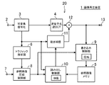
<第1の実施形態>
図1は第1の実施形態に係る画像再生装置1の構成を示す図である。図1の構成において、入力端子2には、再生対象となる動画像ストリームが順次入力される。可変長復号化部3は、入力された動画像ストリームの可変長復号化を行い、各種の符号化パラメータと量子化係数を出力する。ここでの符号化パラメータは、ピクチャタイプ(I/P/Bピクチャ)をはじめ、マクロブロックの符号化タイプ(イントラ/インター)、予測方向種別(前方予測/後方予測/双方向予測)、動き補償サイズおよび動きベクトル等を含む。逆量子化・逆DCT部4は、可変長長復号化部3から出力された量子化係数に対して逆量子化と逆DCT変換を行う。
<First Embodiment>
FIG. 1 is a diagram illustrating a configuration of an
参照画像メモリ5は、すでにデコードされたピクチャを参照画像として一時的に記憶する。トラフィック解析部6は、可変長復号化部3から出力された符号化パラメータに基づいて、参照画像メモリ5に対するトラフィックをピクチャ単位で事前に解析する。設定端子7には、参照画像メモリ5の許容メモリバンド幅(所定の閾値)が設定される。参照画像圧縮制御部8は、トラフィック解析部6において算出された各ピクチャに係る参照画像メモリ5に対するトラフィックを一時的に保持し、デコード対象ピクチャを参照するピクチャに係るトラフィックと設定された許容メモリバンド幅とを比較することによって、参照画像メモリ5への参照画像の格納における圧縮態様を設定する。
The
書き込み制御部9は、参照画像圧縮制御部8によって設定された圧縮態様に従って、参照画像メモリ5への参照画像の書き込みの制御を行う。読み出し制御部10は、参照画像圧縮制御部8によって設定された圧縮態様に応じた伸張態様と、可変長復号化部3から出力された動きベクトルに従って、参照画像メモリ5からの参照画像の読み出しの制御を行う。動き補償部11は、読み出し制御部10によって読み出された参照画像から、可変長復号化部3から出力された動きベクトルに基づいて、予測画像を生成する。加算器12は、画面内予測(イントラ)符号化されているマクロブロックについては、逆量子化・逆DCT部4から出力された画像データをそのまま出力する一方、画面間予測(インター)符号化されているマクロブロックについては、逆量子化・逆DCT部4から出力される画像データと動き補償部11から出力された予測画像とを加算して出力する。出力端子13は、加算器12の出力を再生画像として出力する。
The
図1の構成では、可変長復号化部3、逆量子化・逆DCT部4、動き補償部11および加算器12によって、デコード処理部20が構成されている。このデコード処理部20は、画面間予測符号化された動画像ストリームについてピクチャ単位で可変長復号化を行い、再生画像を生成するとともに、参照画像メモリ5に対するトラフィックの見積もりのために符号化パラメータを出力するものであれば、他の構成であってもかまわない。
In the configuration of FIG. 1, the variable
以下、図1の画像再生装置1を用いて動画像ストリームを再生する手順について、図2〜図5を用いて順に説明する。
Hereinafter, a procedure for reproducing a moving image stream using the
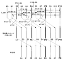
図2は動画像ストリームのピクチャ構成の一例を示す図である。図2では、動画像ストリームの各ピクチャを、上段は入力順に、中段は符号化順に、そして下段は再生順に、それぞれ示している。また、図2では、参照ピクチャを太実線および太字で示している。 FIG. 2 is a diagram illustrating an example of a picture configuration of a moving image stream. In FIG. 2, each picture of the moving image stream is shown in the order of input, the middle part in the order of encoding, and the lower part in the order of reproduction. In FIG. 2, the reference picture is indicated by a bold solid line and bold characters.
図2の上段では、画面間予測符号化を用いて符号化されている各ピクチャ(P/Bピクチャ)の参照ピクチャと、予測画像を生成するために発生する参照ピクチャのリードトラフィック(RT)とを示している。例えば、符号化順で5番目に位置するB3ピクチャの前方予測用の参照ピクチャはI2ピクチャであり、B3ピクチャをデコードする際に発生するI2ピクチャ参照のためのリードトラフィックを『RT(I2→B3)』と図示している。一方、B3ピクチャの後方予測用の参照ピクチャはP5ピクチャであり、B3ピクチャをデコードする際に発生するP5ピクチャ参照のためのリードトラフィックを『RT(B3←P5)』と図示している。また、図2の上段には、他のピクチャをデコードする場合に参照ピクチャとして参照され得るピクチャ(I/Pピクチャ)の参照画像メモリへのライトトラフィック(WT)についても示している。例えば、I2ピクチャのライトトラフィックは『WT(I2)』と図示している。 In the upper part of FIG. 2, the reference picture of each picture (P / B picture) encoded using inter-picture predictive coding, and the read traffic (RT) of the reference picture generated to generate the predicted picture are shown. Is shown. For example, the reference picture for forward prediction of the B3 picture located fifth in the coding order is the I2 picture, and read traffic for I2 picture reference generated when decoding the B3 picture is “RT (I2 → B3 ) ”. On the other hand, the reference picture for backward prediction of the B3 picture is the P5 picture, and the read traffic for referring to the P5 picture generated when the B3 picture is decoded is shown as “RT (B3 ← P5)”. The upper part of FIG. 2 also shows the write traffic (WT) to the reference image memory of a picture (I / P picture) that can be referred to as a reference picture when other pictures are decoded. For example, the write traffic of the I2 picture is illustrated as “WT (I2)”.
本実施形態では、動画像ストリームをデコード再生する際に実際に生じる参照画像メモリに対するトラフィックを事前に解析して、これらのトラフィックが画像再生装置1に搭載されている参照画像メモリ5の許容メモリバンド幅を超える場合は、参照画像を圧縮して参照画像メモリ5に格納する一方、許容メモリバンド幅を超えない場合は参照画像を圧縮せずにそのまま参照画像メモリ5に格納する。これにより、参照画像圧縮による歪の時間的な伝播が極力抑制されるように、制御がなされる。すなわち、従来は、動画像ストリームをデコードする上で発生し得る全てのケースを考慮し、非常に発生確率の低いワーストケースを想定して参照画像メモリに対するトラフィックを見積もっていた。このため、再生対象の動画像ストリームをデコード再生した場合に実際には参照画像メモリの許容メモリバンド幅を超えない場合でも、常に参照画像の圧縮が行われていた。これに対して本実施形態では、動画像ストリームをデコード再生する前に、デコード対象となる各ピクチャを再生した際に実際に発生するトラフィックを事前に解析するためのトラフィック見積もり用デコードを先行して行う。このため、再生用デコード時に参照画像の圧縮が必要と判断されたピクチャに限って参照画像の圧縮が行われるが、それ以外の場合は参照画像の圧縮は行われない。
In the present embodiment, the traffic to the reference image memory actually generated when the moving image stream is decoded and reproduced is analyzed in advance, and these traffics are allowed in the allowable memory band of the
すなわち、画面間予測符号化された動画像ストリームは、通常、ピクチャ内の各マクロブロックの符号化効率が高くなるような符号化の形式が適宜選択される。このため、PピクチャやBピクチャにおいても、全てのマクロブロックが画面間予測符号化されているとは限らず、参照画像をリードする必要がない画面内予測符号化がなされたマクロブロックが多く存在する場合もある。また、画面間予測符号化されているマクロブロックの全てについて、参照画像メモリに対してオーバーヘッドの大きなリードアクセス(より小さなサイズでの動き補償など)が必要となるとは限らない。また、Bピクチャにおいても、全てのマクロブロックについて前後2つのピクチャを参照する双方向予測を用いた符号化が行われているとは限らず、前方予測のみ、あるいは後方予測のみを用いた片方向予測を用いた符号化が行われている場合もある。 That is, for a video stream that has undergone inter-screen predictive coding, a coding format that increases the coding efficiency of each macroblock in a picture is appropriately selected. For this reason, even in the P picture and the B picture, not all macroblocks are subjected to inter-picture predictive coding, and there are many macroblocks that have been subjected to intra-picture predictive coding that do not need to read the reference image. There is also a case. In addition, for all macroblocks that have been subjected to inter-picture predictive coding, read access with a large overhead (such as motion compensation with a smaller size) is not necessarily required for the reference image memory. Also, in B pictures, encoding using bi-directional prediction that refers to two pictures before and after is not performed for all macroblocks, and unidirectional using only forward prediction or only backward prediction. There is a case where encoding using prediction is performed.
以上のように本実施形態では、参照画像の圧縮を必要に応じて最小限に適用するため、従来技術と比較して、より好ましいメモリバンド幅削減を図ることが可能となる。 As described above, in the present embodiment, since the compression of the reference image is applied to the minimum as necessary, it is possible to achieve a more preferable memory bandwidth reduction as compared with the related art.
図3および図4を用いて、本実施形態における具体的な制御フローについて説明する。図3はトラフィック見積もり用デコードを示すフローチャート、図4は再生画像を生成する再生用デコードを示すフローチャートである。ここでは図2に示す動画像ストリームを再生するものとする。 A specific control flow in the present embodiment will be described with reference to FIGS. 3 and 4. FIG. 3 is a flowchart showing traffic estimation decoding, and FIG. 4 is a flowchart showing playback decoding for generating a playback image. Here, it is assumed that the moving image stream shown in FIG. 2 is reproduced.
まず図3を用いて、トラフィック見積もり用デコードの処理について具体的に説明する。なお、トラフィック見積もり用デコードでは、参照画像メモリに対するトラフィックをピクチャ毎に見積もるだけであり、参照画像メモリから参照画像を実際に読み出して予測画像を生成したり、あるいは、再生画像を以降のデコードに必要となる参照画像として参照画像メモリに書き込んだりはしない。このため、参照画像メモリに対するアクセスは行われず、トラフィックは一切発生しない。 First, the traffic estimation decoding process will be described in detail with reference to FIG. Note that the traffic estimation decoding only estimates the traffic to the reference image memory for each picture, and the prediction image is generated by actually reading the reference image from the reference image memory, or the reproduced image is necessary for the subsequent decoding. The reference image is not written in the reference image memory. Therefore, access to the reference image memory is not performed and no traffic is generated.
まず、トラフィック見積もり用デコードが起動され、可変長復号化部3が、入力された動画像ストリームを先頭のI2ピクチャから符号化順に順次デコードし、各種の符号化パラメータをトラフィック解析部6に順次出力する(ST101)。次に、トラフィック解析部6が、トラフィック見積もり対象ピクチャのデコードが終了したか否かを判断する。1ピクチャ分のデコードが完了したとき、ST103に移行する(ST102)。
First, traffic estimation decoding is activated, and the variable
次に、トラフィック解析部6は、デコードされたトラフィック見積り対象ピクチャのピクチャタイプを識別する(ST103)。IピクチャまたはPピクチャのときは、参照画像メモリ5へのライトアクセスが発生するため、ライトトラフィックが算出される(ST104)。ライトトラフィックについては、ピクチャの解像度が分かれば容易に算出できる。Pピクチャのときは、さらに、前方予測対象ピクチャを参照する場合に発生するリードトラフィックが各種符号化パラメータに基づいて算出される(ST107)。一方、Bピクチャのときは、後方予測用ピクチャを参照する場合に発生するリードトラフィックが各種符号化パラメータに基づいて算出され(ST106)、さらに、前方予測用ピクチャを参照する場合に発生するリードトラフィックが同様に算出される(ST107)。
Next, the
最後に、トラフィック見積り対象ピクチャがまだ残っているか否かの判断が行われ(ST108)、残っている場合は、ST101に移行して、上述した動作が繰り返し行われる。 Finally, it is determined whether or not the traffic estimation target picture still remains (ST108). If it remains, the process proceeds to ST101 and the above-described operation is repeated.
このようにトラフィック見積もり用デコードを実行することによって、各ピクチャをデコードする際に発生する参照画像メモリ5の具体的なトラフィックがトラフィック解析部6において算出される。すなわち、図2に示す動画像ストリームを再生した場合に生じるピクチャ毎のトラフィックは、次のような簡単な算出式を用いて事前に求められる。ただし、ST(X)はXピクチャのトラフィックを表す。
By executing the traffic estimation decoding in this way, the
ST(B0)=RT(B0←I2) …(式1)
ST(B1)=RT(B1←I2) …(式2)
ST(I2)=WT(I2) …(式3)
ST(B3)=RT(I2→B3)+RT(B3←P5) …(式4)
ST(B4)=RT(I2→B4)+RT(B4←P5) …(式5)
ST(P5)=WT(P5)+RT(I2→P5) …(式6)
ST(B6)=RT(P5→B6)+RT(B6←P8) …(式7)
ST(B7)=RT(P5→B7)+RT(B7←P8) …(式8)
ST(P8)=WT(P8)+RT(P5→P8) …(式9)
ST (B0) = RT (B0 ← I2) (Formula 1)
ST (B1) = RT (B1 ← I2) (Formula 2)
ST (I2) = WT (I2) (Formula 3)
ST (B3) = RT (I2 → B3) + RT (B3 ← P5) (Formula 4)
ST (B4) = RT (I2 → B4) + RT (B4 ← P5) (Formula 5)
ST (P5) = WT (P5) + RT (I2 → P5) (Formula 6)
ST (B6) = RT (P5 → B6) + RT (B6 ← P8) (Expression 7)
ST (B7) = RT (P5 → B7) + RT (B7 ← P8) (Equation 8)
ST (P8) = WT (P8) + RT (P5 → P8) (Equation 9)
上のようなトラフィック見積もり用デコードにおいて事前に算出された各ピクチャのトラフィックと、参照画像メモリ5の許容メモリバンド幅AWとを比較して、再生用デコード時において、参照画像を圧縮する必要があるか否かを適宜判断する。
It is necessary to compare the traffic of each picture calculated in advance in the above-described traffic estimation decoding with the allowable memory bandwidth AW of the
参照画像メモリ5の許容メモリバンド幅AWとは、1ピクチャをデコードする際に許容できる参照画像メモリ5に対するトラフィックである。言いかえると、参照画像メモリ5のバンド幅をピクチャ単位に換算した値である。例えば、1秒間に60枚のピクチャが存在する動画像ストリームを、参照画像メモリ5のメモリとしてデータ幅が32bitのDDR400を用いてデコードした場合は、メモリアクセスにおける転送ロスを20%考慮すると、
AW=(3.2GB/s×0.8)/60=42.7MB/s …(式10)
となる。
The allowable memory bandwidth AW of the
AW = (3.2 GB / s × 0.8) /60=42.7 MB / s (Formula 10)
It becomes.
参照画像を圧縮するか否かの判断は、具体的には例えば次のように行う。いま、図2の動画像ストリームにおいてI2ピクチャを再生用にデコードするものとする。I2ピクチャを参照画像として参照するピクチャは、I2ピクチャの前後に位置するB0,B1,B3,B4およびP5ピクチャの計5枚のピクチャである。これらのピクチャが正常にデコードされるためには、各ピクチャに係る参照画像メモリ5に対するトラフィックが許容メモリバンド幅AW以下に収まらなければならない。すなわち、次の(式11)〜(式15)を満たす必要がある。
Specifically, whether or not to compress the reference image is determined as follows, for example. Assume that the I2 picture is decoded for reproduction in the moving picture stream of FIG. The pictures that refer to the I2 picture as a reference image are a total of five pictures including B0, B1, B3, B4, and P5 pictures located before and after the I2 picture. In order for these pictures to be normally decoded, the traffic to the
ST(B0)≦AW …(式11)
ST(B1)≦AW …(式12)
ST(B3)≦AW …(式13)
ST(B4)≦AW …(式14)
ST(P5)≦AW …(式15)
ST (B0) ≦ AW (Formula 11)
ST (B1) ≦ AW (Formula 12)
ST (B3) ≦ AW (Expression 13)
ST (B4) ≦ AW (Expression 14)
ST (P5) ≦ AW (Formula 15)
そこで、(式11)〜(式15)が全て満足するときは、I2ピクチャをデコードした画像を圧縮せずに参照画像メモリ5に格納し、いずれか1つでも満足しないときは、I2ピクチャをデコードした画像を圧縮して参照画像メモリ5に格納する、といった判断を行う。
Therefore, when all of (Equation 11) to (Equation 15) are satisfied, the image obtained by decoding the I2 picture is stored in the
なお、上のような判断を行うためには、再生用デコードよりも先に、トラフィック見積もり用デコードを開始する必要がある。すなわち、図5に示すように、再生用デコードは、トラフィック見積もり用デコードの開始から、所定数のピクチャ分だけ遅延して開始する必要がある。ここでの遅延量は、動画像ストリームのGOP(Group of Pictures)構成に基づいて設定すればよい。例えば、図2に示すように、IピクチャまたはPピクチャが現れる周期Mが3(IピクチャまたはPピクチャの間に挿入されるBピクチャは2枚)の場合は、少なくとも6ピクチャ分の遅延を設定すればよい。また、M=4(IピクチャまたはPピクチャ間に挿入されているBピクチャが3枚)の場合は、少なくとも8ピクチャ分の遅延を設定すればよい。すなわち、(M×2)枚以上のピクチャ分だけ遅延させればよい。あるいは、再生開始までの遅延時間が大きな問題にならないときは、例えば1GOP分の遅延を設定してもかわない。 In order to make the above determination, it is necessary to start the traffic estimation decoding before the reproduction decoding. That is, as shown in FIG. 5, it is necessary to start reproduction decoding with a delay of a predetermined number of pictures from the start of traffic estimation decoding. The delay amount here may be set based on the GOP (Group of Pictures) configuration of the moving picture stream. For example, as shown in FIG. 2, when the period M in which an I picture or P picture appears is 3 (two B pictures inserted between the I picture or P picture), a delay of at least 6 pictures is set. do it. When M = 4 (three B pictures inserted between I or P pictures), a delay of at least 8 pictures may be set. That is, it is sufficient to delay by (M × 2) or more pictures. Alternatively, when the delay time until the start of reproduction does not become a big problem, for example, a delay of 1 GOP may be set.
次に、図4を用いて再生用デコードの処理について具体的に説明する。この再生用デコードでは、上述したような参照画像を圧縮するか否かの判断がピクチャ単位で行われる。 Next, playback decoding processing will be described in detail with reference to FIG. In this reproduction decoding, whether or not to compress the reference image as described above is determined on a picture-by-picture basis.
まず、再生用デコードが起動され、可変長復号化部3が、入力された動画像ストリームを先頭のI2ピクチャから符号化順に順次デコードする(ST201)。なお、可変長復号化部3はトラフィック見積り用デコードでも動作するため、図5に示すように、互いに排他的に動作するように時分割でデコード処理を行う。また、トラフィック見積り用デコードの場合は、参照画像メモリ5へのアクセスが一切発生しないため、高速処理可能な可変長復号化部3を備えれば、比較的短い時間で1ピクチャ分のデコード処理は終了する。
First, playback decoding is activated, and the variable
次に、デコード対象ピクチャのピクチャタイプの識別が行われる(ST202)。そしてIピクチャまたはPピクチャのときは、参照画像圧縮制御部8が、デコード対象ピクチャを参照するピクチャ全てのトラフィック見積もりが完了しているか否かの確認を行う(ST203)。例えば、デコード対象ピクチャがI2ピクチャであるときは、上述したように、I2ピクチャを参照するピクチャはB0,B1,B3,B4,P5ピクチャであるので、これらのピクチャのトラフィック見積もり用デコードが完了しているか否かが確認される。もし完了していないときは、トラフィック見積り用デコードによって見積りが完了するまで待機する。
Next, the picture type of the decoding target picture is identified (ST202). If it is an I picture or a P picture, the reference image
次に、参照画像圧縮制御部8が、デコード対象ピクチャを参照するピクチャ全てのトラフィックが許容メモリバンド幅AW(閾値)以下か否かの確認を行う(ST204)。例えば、デコード対象ピクチャがI2ピクチャのときは、上述した(式11)〜(式15)が全て満足されるか否かが確認される。あるいは、デコード対象ピクチャがP5ピクチャのときは、
ST(B3)≦AW …(式16)
ST(B4)≦AW …(式17)
ST(B6)≦AW …(式18)
ST(B7)≦AW …(式19)
ST(P8)≦AW …(式20)
といった5つの条件式が全て満足されるか否かの確認が行われる。
Next, the reference image
ST (B3) ≦ AW (Expression 16)
ST (B4) ≦ AW (Expression 17)
ST (B6) ≦ AW (Expression 18)
ST (B7) ≦ AW (Equation 19)
ST (P8) ≦ AW (Formula 20)
Whether or not all the five conditional expressions are satisfied is confirmed.
ST204において、デコード対象ピクチャを参照するピクチャ全てのトラフィックが許容メモリバンド幅AW以下と判断されたときは(Yes)、参照画像圧縮制御部8は、デコード対象ピクチャをデコードして得た画像を圧縮せずに参照画像メモリ5に書き込む設定とし、この設定を一時的に記憶する(ST205)。一方、デコード対象ピクチャを参照するピクチャのトラフィックのうち、1つでも許容メモリバンド幅AWより大きいと判断された場合(No)、参照画像圧縮制御部8は、デコード対象ピクチャをデコードして得た画像を圧縮して参照画像メモリ5に書き込む設定とし、この設定を一時的に記憶する(ST206)。さらに、デコード対象ピクチャを参照するピクチャのトラフィックの更新を行う(ST207)。すなわち、デコード対象ピクチャが圧縮された場合は、デコード対象ピクチャを参照するピクチャのトラフィックも変化するため、このトラフィックの更新を行う。例えば、デコード対象ピクチャがI2ピクチャのときは、I2ピクチャが圧縮されて参照画像メモリ5に記憶されると、I2ピクチャを参照するピクチャであるB0,B1,B3,B4,P5ピクチャのトラフィックST(B0),ST(B1),ST(B3),ST(B4),ST(P5)も変化する。このうち、B3,B4ピクチャのトラフィックST(B3),ST(B4)については、デコード対象ピクチャがP5ピクチャのとき、(式16)、(式17)に示すように、P5ピクチャを圧縮するか否かの判定にも用いられる。よって、トラフィックを更新する必要がある。
When it is determined in ST204 that the traffic of all the pictures that refer to the decoding target picture is equal to or smaller than the allowable memory bandwidth AW (Yes), the reference image
このようにして、デコード対象ピクチャをデコードして生成された復元画像を参照画像メモリ5に格納する際の圧縮態様(ここでは圧縮するか否か)が決定される。なお、ST202においてデコード対象ピクチャがBピクチャと識別された場合は、参照画像メモリ5への書き込みは発生しないため、上述した書き込み設定に関わる処理はスキップして、後述するST208に移行する。
In this way, the compression mode (here, whether to compress) when the restored image generated by decoding the decoding target picture is stored in the
次に、参照画像メモリ5に記憶された参照画像を順次読み出して、デコード対象ピクチャをデコードする処理について説明する。
Next, a process for sequentially reading the reference images stored in the
まず、デコード対象ピクチャのピクチャタイプが再度識別され(ST208)、PピクチャまたはBピクチャのときは、参照画像圧縮制御部8において、デコード対象ピクチャが参照するピクチャが圧縮されているか否かの確認が行われる(ST209)。圧縮された画像のときは(Yes)、対象となる参照画像を参照画像メモリ5から読み出した後、伸張する設定にし(ST210)、圧縮されていない画像のときは(No)、対象となる参照画像を参照画像メモリ5から読み出した後、伸張しない設定にする(ST211)。なお、ST208において、Iピクチャと識別されたときは、参照画像メモリ5から参照画像を読み出す必要がないため、後述するST212にスキップする。
First, the picture type of the decoding target picture is identified again (ST208), and when it is a P picture or a B picture, the reference image
このようにして、デコード対象ピクチャをデコードする際の参照画像の読み出し設定が行われ、ピクチャ内のスライス層以下のデコードが起動される(ST212)。ここでは、書き込み制御部9および読み出し制御部10によって、すでに決定された書き込み/読み出し設定に基づいて、参照画像メモリ5内の参照画像に対してリード/ライトアクセスが行われる。デコード対象ピクチャの1ピクチャ分のデコードが終了したとき、動画像ストリームにおいて再生されていないデコード対象ピクチャが存在するか否かの確認が行われ(ST213)、存在する場合はST201に移行して、上述の処理を再度行い、存在しないときは処理を終了する。
In this way, the reference image is read out when decoding the decoding target picture, and decoding below the slice layer in the picture is activated (ST212). Here, the
なお、上述の説明では、参照画像メモリ5に対するトラフィックをピクチャ単位で精度良く見積もるために、マクロブロックの符号化タイプ、予測方向種別、動き補償サイズおよび動きベクトルといった各種符号化パラメータを用いるものとしたが、トラフィックの見積もり手法はこれに限定されるものではない。例えば、これらの符号化パラメータを全て用いる代わりに、その1つ、またはいくつかを用いて、トラフィックを簡易的に見積もってもかまわない。
In the above description, in order to accurately estimate traffic to the
例えば、ピクチャ内に存在するインターマクロブロックの個数に基づいて、トラフィックを簡易的に見積もってもよい。あるいは、ピクチャについて抽出された動きベクトルの個数に基づいてトラフィックを簡易的に見積もってもよい。さらには、ピクチャについて抽出された動き補償サイズ毎のマクロブロック数に基づいて、トラフィックを簡易的に見積もってもかまわない。 For example, traffic may be simply estimated based on the number of inter macroblocks present in a picture. Alternatively, traffic may be simply estimated based on the number of motion vectors extracted for a picture. Furthermore, traffic may be simply estimated based on the number of macroblocks for each motion compensation size extracted for a picture.
また、上述の説明では、事前に見積もられた各ピクチャのトラフィックそれぞれと許容メモリバンド幅AWとを比較し、この比較処理の結果から、デコード対象ピクチャの圧縮/非圧縮を決定するものとしたが、参照画像の圧縮態様を決定するための比較処理はこれに限定されるものではない。例えば、デコード対象ピクチャを参照する複数のピクチャを1つの単位とし、これらの各ピクチャに係るトラフィックの平均値と許容メモリバンド幅AWとを比較してもよい。具体的には、デコード対象ピクチャがI2ピクチャであるとき、I2ピクチャを参照する5つのピクチャのトラフィックST(B0),ST(B1),ST(B3)、ST(B4)、ST(P5)の平均値と許容メモリバンド幅AWとを比較し、その比較結果から、I2ピクチャから得られた参照画像を圧縮するか否かを決定する。 In the above description, each estimated traffic of each picture is compared with the allowable memory bandwidth AW, and compression / non-compression of the decoding target picture is determined from the result of this comparison process. However, the comparison process for determining the compression mode of the reference image is not limited to this. For example, a plurality of pictures that refer to the decoding target picture may be used as one unit, and the average value of traffic related to each picture may be compared with the allowable memory bandwidth AW. Specifically, when the decoding target picture is an I2 picture, traffic ST (B0), ST (B1), ST (B3), ST (B4), and ST (P5) of five pictures that refer to the I2 picture The average value and the allowable memory bandwidth AW are compared, and from the comparison result, it is determined whether or not to compress the reference image obtained from the I2 picture.
また、上述の説明では、参照画像メモリ5を動画像ストリーム再生のためにのみ用いるものとしたが、参照画像メモリ5は、動画像ストリーム再生とは異なる他の処理にも用いられるメモリであってもよい。この場合は、参照画像メモリ5へのアクセスが互いに競合しないように、動画像ストリーム再生と他の処理とが協調制御される。このとき、比較処理に用いられる許容メモリバンド幅AWは、上述の説明で算出した値から、他の処理が必要とするトラフィックを減じて得た値に設定すればよい。
In the above description, the
また、上述の説明では、許容メモリバンド幅AWを1種類のみ設定し、この許容メモリバンド幅AWとトラフィックとの比較処理によって、参照画像を圧縮するか否かを判定するものとしたが、許容メモリバンド幅AWの設定や圧縮態様の判定はこれに限られるものではない。例えば、所定の閾値としての許容メモリバンド幅AWを複数種類設定できるようにして、この複数の許容メモリバンド幅AWとトラフィックとの比較処理によって、複数の圧縮率の中からいずれかを選択するという方法を用いてもかまわない。具体的には例えば、2個の許容メモリバンド幅AW1,AW2を設定し、この許容メモリバンド幅AW1,AW2と各ピクチャのトラフィックとを比較して、各ピクチャのトラフィックがAW1以下であればデコード対象ピクチャを圧縮せず、AW1より大きくAW2以下であればデコード対象ピクチャを75%に圧縮し、AW2より大きければデコード対象ピクチャをより圧縮率の高い50%に圧縮するものと判定する。 In the above description, only one type of allowable memory bandwidth AW is set, and it is determined whether or not the reference image is compressed by a comparison process between the allowable memory bandwidth AW and traffic. The setting of the memory bandwidth AW and the determination of the compression mode are not limited to this. For example, a plurality of allowable memory bandwidths AW as predetermined threshold values can be set, and one of a plurality of compression rates is selected by a comparison process between the plurality of allowable memory bandwidths AW and traffic. The method may be used. Specifically, for example, two allowable memory bandwidths AW1 and AW2 are set, the allowable memory bandwidths AW1 and AW2 are compared with the traffic of each picture, and if the traffic of each picture is AW1 or less, decoding is performed. If the target picture is not compressed and is larger than AW1 and smaller than or equal to AW2, the decoding target picture is compressed to 75%, and if it is larger than AW2, the decoding target picture is determined to be compressed to 50% with a higher compression rate.
また、参照画像を圧縮する場合は、輝度成分と色差成分とにそれぞれ独立した圧縮率を設定してもよい。例えば、輝度成分の歪は人間の目にも確認されやすいため、色差成分の圧縮率よりも輝度成分の圧縮率の方が低くなるような設定にする方がより好ましい。 In addition, when compressing the reference image, independent compression rates may be set for the luminance component and the color difference component. For example, since the distortion of the luminance component is easily recognized by human eyes, it is more preferable to set the luminance component so that the compression ratio of the luminance component is lower than the compression ratio of the color difference component.
以上のように本実施形態によると、動画像ストリームをデコードして再生する場合に、実際に生じる参照画像メモリに対するトラフィックをピクチャ単位で事前に見積もり、それらのトラフィックが参照画像メモリの許容メモリバンド幅を超える場合に、参照画像を圧縮して格納する。これにより、デコード時に発生する参照画像圧縮による歪の時間的な伝播を極力抑制することができる。また、発生確率の極めて低いワーストケースを想定して、必要以上の高性能なメモリを搭載する必要がないため、低コスト化と省電力化を同時に実現できる。また、従来のように、圧縮した参照画像と非圧縮の参照画像の両方を記憶させておく必要がないため、比較的少ないメモリ容量で実現できるとともに、参照画像メモリへのライトアクセスも2重に発生しない。 As described above, according to the present embodiment, when a moving image stream is decoded and reproduced, traffic to the reference image memory that actually occurs is estimated in advance in units of pictures, and the traffic is an allowable memory bandwidth of the reference image memory. If it exceeds, the reference image is compressed and stored. Thereby, temporal propagation of distortion due to reference image compression that occurs during decoding can be suppressed as much as possible. In addition, assuming the worst case with a very low probability of occurrence, it is not necessary to mount a higher-performance memory than necessary, so that both cost reduction and power saving can be realized simultaneously. In addition, since it is not necessary to store both a compressed reference image and an uncompressed reference image as in the prior art, it can be realized with a relatively small memory capacity, and write access to the reference image memory is also doubled. Does not occur.
<第2の実施形態>
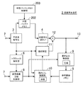
図6は第2の実施形態に係る画像再生装置2の構成を示す図である。図6において、図1と共通の構成要素には図1と同一の符号を付しており、ここではその詳細な説明を省略する。図6の構成において第1の実施形態と異なるのは、可変長復号化部3においてデコードされた中間データを一時的に記憶しておくための中間バッファメモリ202と、中間バッファメモリ202の書き込み/読み出し制御を行う中間バッファメモリ制御部203とが追加されている点である。
<Second Embodiment>
FIG. 6 is a diagram illustrating a configuration of the
第1の実施形態の場合、トラフィック見積もり用デコードと再生用デコードとをタイミングをずらして起動し、可変長復号化部3を排他的に動作させていた。ところが、先行して実行されるトラフィック見積り用デコードで一旦、動画像ストリームの可変長復号化を行った後に、また再度、再生用デコードのために同一ストリームの可変長復号化を行うため、デコード処理に重複があり、再生用デコードに余分な時間が発生する。本実施形態は、この再生用デコードにおける余分な時間を削除することを目的とするものである。
In the case of the first embodiment, the traffic estimation decoding and the reproduction decoding are started at different timings, and the variable
以下、本実施形態における処理を具体的に説明する。 Hereinafter, the process in this embodiment is demonstrated concretely.
まず、第1の実施形態と同様に、トラフィック見積り用デコードが先行して起動され、可変長復号化部3は、ピクチャ毎の具体的なトラフィックを見積もるために、ピクチャ層だけではなく、スライス層、マクロブロック層までの全てのデコードを行う。そして第1の実施形態では、デコードされたデータのうち、トラフィック見積りに必要となる各種符号化パラメータがトラフィック解析部6に順次出力されるだけであったが、本実施形態ではこれに加えて、デコードされたマクロブロック層の画像データ(量子化係数)を中間データとして一時的に中間バッファメモリ202に格納する。すなわち、可変長復号化部3から順次出力されるマクロブロック層の画像データが、中間バッファメモリ制御部203の書き込み制御によって、中間バッファメモリ202に記憶される。
First, as in the first embodiment, the traffic estimation decoding is started in advance, and the variable
そして再生用デコードでは、動画像ストリームを再度、可変長復号化するのではなく、中間バッファメモリ202に一時的に記憶されているデコード対象ピクチャの画像データが、中間バッファメモリ制御部203の読み出し制御によって順次読み出され、この画像データを用いてデコード処理が行われる。
In the decoding for reproduction, the video data of the decoding target picture temporarily stored in the
このように本実施形態によると、トラフィック見積り用デコードにおけるデコード処理で得られた中間データを中間バッファメモリ202に一時的に格納し、再生用デコードにおいて、中間バッファメモリ202から中間データを読み出し、再生画像を生成する。これにより、ピクチャ毎の可変長復号化が1回で済むことになり、したがって、再生用デコード処理の高速化を図ることができる。また、高速処理が可能な可変長復号化器を設ける必要性もなくなるという効果も得られる。
As described above, according to the present embodiment, the intermediate data obtained by the decoding process in the traffic estimation decoding is temporarily stored in the
なお、上述の説明では、可変長復号化により生成された画像データ(量子化係数)を中間データとして中間バッファメモリ202に記憶させるものとしたが、中間バッファメモリ202に格納する中間データはこれに限られるものではない。例えば、二値化処理と算術符号化を組み合わせて可変長符号化されているH.264の動画像ストリームをデコードする場合には、算術復号化された後の二値化データを中間データとして中間バッファメモリ202に記憶させてもよい。この二値化データは、画像データ(量子化係数)が圧縮されているものに相当するので、これを中間データとして格納することによって、中間バッファメモリ202を比較的小容量のメモリで構成することができる。
In the above description, the image data (quantization coefficient) generated by variable length decoding is stored in the
また、上述の説明は、参照画像メモリ5と中間バッファメモリ202はそれぞれ独立して構成されているものとしたが、これに限られるものではなく、参照画像メモリ5と中間バッファメモリ202とが単一の共有メモリで構成されていてもよい。この場合は、互いの動作に影響が出ないよう、排他的に制御すればよい。
In the above description, the
<第3の実施形態>
図7は第3の実施形態に係る画像再生方法を示すフローチャートである。本実施形態では、第1および第2の実施形態で説明した画像再生方法を用いて動画像ストリームを再生している間に、一時停止やコマ送りなどを行う場合の処理について具体的に説明する。
<Third Embodiment>
FIG. 7 is a flowchart showing an image reproduction method according to the third embodiment. In the present embodiment, a specific description will be given of processing in the case where a pause or a frame advance is performed while a moving image stream is being reproduced using the image reproduction method described in the first and second embodiments. .
第1および第2の実施形態で説明した画像再生方法は、参照画像メモリ5に対するトラフィックが許容メモリバンド幅を超える場合にのみ参照画像を圧縮するため、デコード時に発生する参照画像圧縮による歪の時間的な伝播を極力抑制することができる。ところが、許容メモリバンド幅が比較的小さい参照画像メモリ5を用いて画像再生装置を構成したり、参照画像メモリ5に対するトラフィックが大きな動画像ストリームを再生したりした場合は、参照画像圧縮が頻繁に行われ、参照画像圧縮による歪の時間的な伝播も大きくなる。ただ、このような場合でも、通常の動画再生のときは、参照画像圧縮による歪は視覚的には比較的気づきにくく大きな問題とはならないが、例えば、一時停止して静止画が表示されたときやコマ送りを行ったときは、歪はより目につきやすくなる。
Since the image reproduction methods described in the first and second embodiments compress the reference image only when the traffic to the
そこで本実施形態では、一時停止やコマ送り再生など、参照画像圧縮による歪が視覚的に気づかれやすい状況になった場合は、ピクチャ毎のトラフィックに関わらず、参照画像を圧縮しないように制御変更することを特徴とする。 Therefore, in this embodiment, when distortion due to reference image compression is easily noticed, such as pause or frame advance playback, the control is changed so that the reference image is not compressed regardless of the traffic for each picture. It is characterized by doing.
以下、図7を用いて具体的に説明する。 Hereinafter, this will be specifically described with reference to FIG.
まず、第1および第2の実施形態で説明した画像再生方法を用いて動画像ストリームを再生中に、一時停止やコマ送りが指示されたか否かを判断する(ST301)。動画像再生中にいきなりコマ送りが行われることはないので、動画の通常再生中であればまず一時停止が指示されたか否かの判断が行われる。一時停止が指示されていないときは(No)、そのまま参照画像を圧縮制御(各ピクチャのトラフィックに応じて圧縮態様を設定)する設定で、動画像ストリームを再生する(ST302)。一方、一時停止が指示されたときは(Yes)、一時停止直後か否かの判断が行われ(ST303)、一時停止直後のときは(Yes)、参照画像圧縮による歪が目につきやすいため、一時停止時の再生ピクチャより前のIピクチャに戻って(ST304)、参照画像を圧縮しない設定で再度デコード処理を行う(ST305)。次に、デコードされたピクチャが一時停止時の再生ピクチャと同じか否かの判断が行われ(ST306)、同じでないときは(No)、ST305に移行して参照画像を圧縮しない設定で次のピクチャが再デコードされる。同様にピクチャが順次再デコードされ、一時停止時の再生ピクチャと同じピクチャが再デコードされたとき(Yes)、再生画像の差し替えが行われ(ST307)、ST301に移行する。また、一時停止の後、継続してコマ送りが行われるときは(ST301でYes、ST303でNo)、参照画像圧縮による歪が時間的に伝播しないよう、参照画像を圧縮しない設定でデコード処理を行う(ST308)。 First, it is determined whether pause or frame advance is instructed during playback of a moving image stream using the image playback method described in the first and second embodiments (ST301). Since frame advance is not performed suddenly during moving image reproduction, it is first determined whether or not a pause is instructed during normal reproduction of a moving image. When the pause is not instructed (No), the moving image stream is reproduced with the setting for performing compression control of the reference image as it is (setting the compression mode according to the traffic of each picture) (ST302). On the other hand, when the pause is instructed (Yes), it is determined whether or not it is immediately after the pause (ST303), and immediately after the pause (Yes), distortion due to the reference image compression is easily noticeable. Returning to the I picture before the reproduction picture at the time of pause (ST304), the decoding process is performed again with the setting that the reference image is not compressed (ST305). Next, it is determined whether or not the decoded picture is the same as the reproduced picture at the time of pause (ST306). If not (No), the process proceeds to ST305 and the reference image is not compressed and the next is set. The picture is re-decoded. Similarly, when pictures are sequentially re-decoded and the same picture as the reproduced picture at the time of pause is re-decoded (Yes), the reproduced image is replaced (ST 307), and the process proceeds to ST 301. Further, when frame advance is continuously performed after the pause (Yes in ST301, No in ST303), the decoding process is performed with the setting that the reference image is not compressed so that the distortion due to the reference image compression does not propagate in time. Perform (ST308).
このように、一時停止して静止画が表示された場合やコマ送りされた場合など、参照画像圧縮による歪が視覚的に発見されやすい場合は、参照画像を圧縮しない設定でデコード処理を行う。これにより、一時停止やコマ送りにおいて、参照画像圧縮による歪が回避されるので、より好ましい動画像ストリームの再生が実現でき、実使用シーンを想定した好ましい画像再生装置を実現できる。 As described above, when distortion due to the reference image compression is easily found visually, such as when the still image is displayed after being paused or when the frame is advanced, the decoding process is performed with the setting that the reference image is not compressed. Thereby, distortion caused by reference image compression is avoided in pause and frame advance, so that a more preferable moving image stream can be reproduced, and a preferable image reproducing device assuming an actual use scene can be realized.
なお、本実施形態では、一時停止の場合、Iピクチャに遡って参照画像を圧縮しない設定で再度デコード処理を行い表示画像を差し替えるため、参照画像圧縮による歪のない再生画像が生成されるまでに若干のタイムラグが生じることになる。ただし、実際の画像再生装置では、このタイムラグは最大でも0.5秒程度であるため、視聴者の体感速度の面からみて大きな問題にはならない。また、コマ送りの場合も、参照画像を圧縮しない設定で許容メモリバンド幅を超えたトラフィックの中でデコードを行うため、若干、デコード処理に時間を要することになる。ただし、コマ送り再生は、通常の動画再生に比べてリアルタイム性が要求されるものではないため、大きな問題にならない。 In the present embodiment, in the case of pause, since the display image is replaced by decoding again with the setting that does not compress the reference image retroactively to the I picture, the reproduction image without distortion by the reference image compression is generated. There will be some time lag. However, in an actual image reproducing apparatus, this time lag is about 0.5 seconds at the maximum, so this is not a big problem from the viewpoint of the viewer's perceived speed. Also, in the case of frame advance, since decoding is performed in traffic exceeding the allowable memory bandwidth with the setting of not compressing the reference image, it takes some time for the decoding process. However, frame-by-frame playback is not a big problem because real-time performance is not required compared to normal video playback.
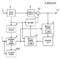
<第4の実施形態>
図8は第4の実施形態に係る画像再生装置4の構成を示す図、図9は第4の実施形態に係る画像再生方法を示すフローチャートである。図8において、図1と共通の構成要素には図1と同一の符号を付しており、ここではその詳細な説明を省略する。図8の構成において、第1の実施形態と異なるのは、一時停止やコマ送りなどが発生した場合に、参照画像圧縮による歪の伝搬に起因した、再生画像の劣化度合を判定する劣化度合判定部402が追加されている点である。また、図9において、図7と共通のステップには図7と同一の符号を付しており、ここではその詳細な説明を省略する。図9のフローにおいて第3の実施形態と異なるのは、一時停止やコマ送りなどが発生した場合に、再生画像の劣化度合を判定するステップST401が追加されている点である。
<Fourth Embodiment>
FIG. 8 is a diagram showing a configuration of an
すなわち、第1および第2の実施形態で説明した、参照画像の圧縮態様を制御する設定で動画像ストリームを再生している場合において、一時停止が指示されたとき、その時の再生ピクチャは、参照画像圧縮による歪の時間的な伝播が大きい場合と小さい場合とが存在する。例えば、参照画像圧縮による歪の時間的伝播がないIピクチャが再生された後、比較的早い段階で一時停止された場合は、参照画像圧縮による歪の時間的伝播が少ないため、Iピクチャに遡った再デコード処理を行わなくてもさほど問題はない。一方、Iピクチャが再生された後しばらく経過してから一時停止された場合は、参照画像圧縮による歪の時間的伝播が大きいため、Iピクチャに遡った再デコード処理を行わなければ、参照画像圧縮による歪が画像上発見されやすくなる。 That is, in the case where a moving image stream is reproduced with the setting for controlling the compression mode of the reference image described in the first and second embodiments, when a pause is instructed, the reproduced picture at that time is referred to There are cases where the temporal propagation of distortion due to image compression is large and small. For example, if an I picture that has no temporal propagation of distortion due to reference image compression is played back and then paused at a relatively early stage, the temporal propagation of distortion due to the reference image compression is small, so that the I picture is traced back. There is no problem even if re-decoding is not performed. On the other hand, if the I picture is paused for a while after being played back, the temporal propagation of distortion due to the reference picture compression is large. Therefore, if re-decoding processing going back to the I picture is not performed, the reference picture compression is performed. Distortion due to is likely to be found on the image.
本実施形態では、このような判断処理を、劣化度合判定部402がステップST401において行うことを特徴とする。すなわち、ステップST401では、一時停止時の再生ピクチャからデコードされた再生画像の劣化度合が大きいか否かを判断する。そして、劣化度合が相対的に大きいときは(Yes)、一時停止時の再生ピクチャより前のIピクチャに戻って(ST304)、参照画像を圧縮しない設定で再度デコード処理を行う(ST305)。同様にピクチャが順次再デコードされ、一時停止時の再生ピクチャと同じピクチャが再デコードされたとき(ST306でYes)、再生画像の差し替えが行われる(ST307)。一方、劣化度合が相対的に小さいときは(ST401でNo)、その後、参照画像を圧縮しない設定で、デコードを行う(ST308)。ステップST401を追加したことによって、第3の実施形態と比べて、Iピクチャに遡った再デコード処理を行う回数を少なく抑えることができる。
The present embodiment is characterized in that such a determination process is performed by the deterioration
なお、ステップST401での判定処理は、例えば次のように行う。すなわち、一時停止時の再生画像の劣化度合を判定するための閾値として、画質的に許容できるIピクチャからの時間的な距離が設定端子7から設定される。そして、Iピクチャから一時停止時の再生ピクチャまでの時間的な距離をこの閾値と比較することによって、劣化度合が大きいか小さいかを判定する。あるいは、Iピクチャからの時間的な距離に代えて、あるいはこれに加えて、一時停止時の再生ピクチャへの、参照画像圧縮による歪の伝搬回数を用いて判断してもよい。
The determination process in step ST401 is performed as follows, for example. That is, as a threshold value for determining the degree of degradation of the reproduced image at the time of pause, a temporal distance from the I picture that is acceptable in terms of image quality is set from the setting
(システムの構成例)
上述の各実施形態に係る画像再生方法は、例えばデジタルビデオカメラやデジタルスチルカメラ等の撮像システム(映像システム)に利用することができる。図10はそのような撮像システムの構成の一例を示すである。図10の撮像システムは、各実施形態に係る画像再生方法を利用したシステムであり、画像処理回路53は、各実施形態に係る画像再生方法を実行可能な画像再生部100を含み、画像処理を行う。
(System configuration example)
The image reproduction method according to each of the above-described embodiments can be used for an imaging system (video system) such as a digital video camera or a digital still camera. FIG. 10 shows an example of the configuration of such an imaging system. The imaging system of FIG. 10 is a system that uses the image reproduction method according to each embodiment, and the
図10の撮像システムでは、光学系50を通って入射した画像光はセンサー51上に結像され、光電変換される。光電変換によって得られた電気信号はA/D変換回路52にアナログ画像信号として与えられる。A/D変換回路52は入力されたアナログ画像信号をデジタル画像信号に変換した後、画像処理回路53に出力する。画像処理回路53では、Y/C処理、エッジ処理、画像の拡大縮小、およびJPEGやMPEG等の画像圧縮/伸張処理,画像圧縮されたストリームの制御等が行われる。画像処理された信号は、記録系/転送系54において、メディアに記録されたり、あるいはインターネット等を介して転送されたりする。記録または転送された信号は再生系55によって再生される。センサー51および画像処理回路53はタイミング制御回路56により制御され、光学系50、記録系/転送系54,再生系55およびタイミング制御回路56は、各々、システム制御回路57により制御される。
In the imaging system of FIG. 10, the image light incident through the
なお、図10に示した撮像システムでは、光学系50からの画像光をセンサー51で光電変換してA/D変換回路52に入力する、カメラ機器等に用いられる構成としたが、これに限定されるものではない。例えば、テレビ等のAV機器のアナログ映像入力をアナログ画像信号として直接にA/D変換回路52に供給する構成であってもよい。
In the imaging system shown in FIG. 10, the image light from the
また、図10に示した撮像システムから光学系50やセンサー51等の撮像に関する部分を省いた構成の再生システムにも、上述の各実施形態は同様に適用可能である。
In addition, the above-described embodiments can be similarly applied to a reproduction system having a configuration in which the imaging system such as the
なお、上述の各実施形態に係る画像再生方法は、当該方法を実現するためのプログラムを実行するコンピュータを備えた装置によって実現することができる。また、当該方法を実現するためのプログラムをコンピュータ読み取り可能な記録媒体に記録して、この記録媒体に記録したプログラムをコンピュータに実行させることによって実現することができる。 Note that the image reproduction methods according to the above-described embodiments can be realized by an apparatus including a computer that executes a program for realizing the method. Further, it can be realized by recording a program for realizing the method on a computer-readable recording medium and causing the computer to execute the program recorded on the recording medium.
本発明では、低コスト・省電力で、デコード時に発生する圧縮歪の時間的な累積を抑制可能な画像再生技術を実現できるので、例えば、安価で、かつ高速、省電力な動画像再生が要求される、デジタルビデオカメラやデジタルスチルカメラ等の撮像機器、デジタルフォトストレージやデジタルフォトフレームなどの画像ビューワ、および携帯電話などのモバイル機器などに有用である。 In the present invention, since it is possible to realize an image reproduction technique capable of suppressing the temporal accumulation of compression distortion generated at the time of decoding at low cost and power saving, for example, inexpensive, high-speed and power-saving moving image reproduction is required. It is useful for imaging devices such as digital video cameras and digital still cameras, image viewers such as digital photo storage and digital photo frames, and mobile devices such as mobile phones.
1,2,4 画像再生装置
2 可変長復号化部
4 逆量子化・逆DCT部
5 参照画像メモリ
6 トラフィック解析部
8 参照画像圧縮制御部
9 書き込み制御部
10 読み出し制御部
11 動き補償部
12 加算器
20 デコード処理部
50 光学系
51 センサー
52 A/D変換回路
53 画像処理回路
100 画像再生部
202 中間バッファメモリ
402 劣化度合判定部
1, 2, 4
20
Claims (30)
前記参照画像メモリに対するトラフィックをピクチャ単位で見積もるために、前記動画像ストリームをピクチャ単位でデコードする第1のデコードステップと、
再生画像を生成するために、前記動画像ストリームをピクチャ単位でデコードする第2のデコードステップとを備え、
前記第2のデコードステップにおいて、
デコード対象ピクチャが、デコード後に参照画像として前記参照画像メモリに格納すべきものであるとき、前記第1のデコードステップにおいて見積もられた、当該デコード対象ピクチャを参照するピクチャに係るトラフィックを基にして、当該デコード対象ピクチャを前記参照画像メモリに格納する際の圧縮態様を設定するものである
ことを特徴とする画像再生方法。 An image reproduction method for decoding a video stream that has been inter-screen predictively encoded while accessing a reference image memory,
A first decoding step of decoding the moving picture stream in units of pictures in order to estimate traffic to the reference picture memory in units of pictures;
A second decoding step of decoding the moving image stream in units of pictures to generate a reproduced image;
In the second decoding step,
When the picture to be decoded is to be stored in the reference picture memory as a reference picture after decoding, based on the traffic related to the picture referring to the picture to be decoded estimated in the first decoding step, An image reproduction method characterized by setting a compression mode when the decoding target picture is stored in the reference image memory.
前記第1のデコードステップは、
前記参照画像メモリに対するアクセスを行わないで、前記動画像ストリームに対する可変長復号化によって、トラフィック見積もりに用いる符号化パラメータを抽出するものである
ことを特徴とする画像再生方法。 The image reproduction method according to claim 1, wherein
The first decoding step includes:
An image reproduction method characterized in that an encoding parameter used for traffic estimation is extracted by variable length decoding of the moving picture stream without accessing the reference picture memory.
前記第1のデコードステップにおいて抽出される符号化パラメータは、マクロブロックの符号化タイプ、予測方向種別、動き補償サイズおよび動きベクトルのうち、少なくとも1つを含む
ことを特徴とする画像再生方法。 The image reproduction method according to claim 2, wherein
The encoding parameter extracted in the first decoding step includes at least one of a macroblock encoding type, a prediction direction type, a motion compensation size, and a motion vector.
前記第1のデコードステップにおいて、
トラフィックの見積もりは、当該ピクチャ内に存在するインターマクロブロックの個数に基づいて、行われる
ことを特徴とする画像再生方法。 The image reproduction method according to claim 2, wherein
In the first decoding step,
An image reproduction method characterized in that the traffic estimation is performed based on the number of inter macroblocks existing in the picture.
前記第1のデコードステップにおいて、
トラフィックの見積もりは、当該ピクチャについて抽出された動きベクトルの個数に基づいて、行われる、
ことを特徴とする画像再生方法。 The image reproduction method according to claim 2, wherein
In the first decoding step,
Traffic estimation is performed based on the number of motion vectors extracted for the picture.
An image reproduction method characterized by the above.
前記第1のデコードステップにおいて、
トラフィックの見積もりは、当該ピクチャについて抽出された動き補償サイズ毎のマクロブロック数に基づいて、行われる、
ことを特徴とする画像再生方法。 The image reproduction method according to claim 2, wherein
In the first decoding step,
Traffic estimation is performed based on the number of macroblocks for each motion compensation size extracted for the picture.
An image reproduction method characterized by the above.
前記第2のデコードステップにおいて、
当該デコード対象ピクチャを参照するピクチャに係るトラフィックについて、所定の閾値との比較処理を行うことによって、当該デコード対象ピクチャを圧縮するか否かを設定する
ことを特徴とする画像再生方法。 The image reproduction method according to claim 1, wherein
In the second decoding step,
An image reproduction method comprising: setting whether or not to compress the decoding target picture by performing a comparison process with a predetermined threshold for traffic related to the picture that refers to the decoding target picture.
前記比較処理において、当該デコード対象ピクチャを参照する複数のピクチャに係るトラフィックをそれぞれ、前記所定の閾値と比較する
ことを特徴とする画像再生方法。 The image reproduction method according to claim 7, wherein
In the comparison processing, the traffic related to a plurality of pictures that refer to the decoding target picture is compared with the predetermined threshold value, respectively.
前記比較処理において、当該デコード対象ピクチャを参照する複数のピクチャに係るトラフィックの平均値を、前記所定の閾値と比較する
ことを特徴とする画像再生方法。 The image reproduction method according to claim 7, wherein
In the comparison process, an average value of traffic relating to a plurality of pictures that refer to the decoding target picture is compared with the predetermined threshold value.
前記所定の閾値は、前記参照画像メモリのバンド幅をピクチャ単位に換算した値である
ことを特徴とする画像再生方法。 The image reproduction method according to claim 7, wherein
The image reproduction method according to claim 1, wherein the predetermined threshold value is a value obtained by converting a bandwidth of the reference image memory in units of pictures.
前記参照画像メモリは、前記動画像ストリームの再生とは異なる他の処理にも用いられるものであり、
前記所定の閾値は、前記参照画像メモリのバンド幅をピクチャ単位に換算した値から前記他の処理が必要とするトラフィックを減じて得た値である
ことを特徴とする画像再生方法。 The image reproduction method according to claim 7, wherein
The reference image memory is used for other processing different from the reproduction of the moving image stream,
The image reproduction method according to claim 1, wherein the predetermined threshold is a value obtained by subtracting traffic required for the other processing from a value obtained by converting a bandwidth of the reference image memory in units of pictures.
前記第2のデコードステップにおいて、
当該デコード対象ピクチャを参照するピクチャに係るトラフィックについて、複数の所定の閾値との比較処理を行うことによって、当該デコード対象ピクチャの圧縮率を設定する
ことを特徴とする画像再生方法。 The image reproduction method according to claim 1, wherein
In the second decoding step,
An image reproduction method characterized in that a compression rate of a decoding target picture is set by performing a comparison process with a plurality of predetermined thresholds for traffic related to the picture that refers to the decoding target picture.
当該デコード対象ピクチャについて、輝度成分と色差成分とにそれぞれ独立した圧縮率を設定する
ことを特徴とする画像再生方法。 The image reproduction method according to claim 12, wherein
An image reproduction method characterized by setting independent compression rates for a luminance component and a color difference component for the decoding target picture.
前記第2のデコードステップは、
デコード対象ピクチャについて設定された圧縮態様を、一時的に記憶するステップを備え、
前記デコード対象ピクチャを前記参照画像メモリから参照画像として読み出す際に、記憶されている圧縮態様に応じた伸張態様で、読み出しを行う
ことを特徴とする画像再生方法。 The image reproduction method according to claim 1, wherein
The second decoding step includes
Temporarily storing the compression mode set for the picture to be decoded;
An image reproduction method characterized in that when the picture to be decoded is read from the reference image memory as a reference image, the picture to be decoded is read in a decompression manner corresponding to a stored compression manner.
前記第2のデコードステップは、前記第1のデコードステップの開始から、所定数のピクチャ分遅延して開始されるものであり、
前記所定数は、前記動画像ストリームのGOP(Group of Pictures)においてIピクチャまたはPピクチャの現れる周期がM(Mは正の整数)のとき、(M×2)以上である
ことを特徴とする画像再生方法。 The image reproduction method according to claim 1, wherein
The second decoding step is started with a delay of a predetermined number of pictures from the start of the first decoding step,
The predetermined number is equal to or greater than (M × 2) when the period in which an I picture or P picture appears in a GOP (Group of Pictures) of the video stream is M (M is a positive integer). Image playback method.
前記第1のデコードステップは、
デコード処理で得られた中間データを、中間バッファメモリに一時的に格納するものであり、
前記第2のデコードステップは、
前記中間バッファメモリから前記中間データを読み出し、この中間データを用いて再生画像を生成する
ことを特徴とする画像再生方法。 The image reproduction method according to claim 1 or 2,
The first decoding step includes:
The intermediate data obtained by the decoding process is temporarily stored in the intermediate buffer memory.
The second decoding step includes
An image reproducing method, wherein the intermediate data is read from the intermediate buffer memory, and a reproduced image is generated using the intermediate data.
前記動画像ストリームを再生中に、一時停止が指示されたとき、
一時停止時の再生ピクチャの前にあるIピクチャに戻り、当該Iピクチャから順次、参照画像を圧縮しない設定で再デコードを行い、
一時停止時の再生ピクチャの再デコードが終了したとき、再生画像の差し替えを行う
ことを特徴とする画像再生方法。 The image reproduction method according to claim 1, wherein
When pause is instructed during playback of the video stream,
Return to the I picture that precedes the playback picture at the time of pause, and re-decode sequentially from the I picture with the setting not to compress the reference picture,
An image reproduction method characterized by replacing a reproduction image when re-decoding of a reproduction picture at the time of pause is completed.
前記動画像ストリームを再生中に、コマ送り再生が指示されたとき、
その後、参照画像を圧縮しない設定で、デコードを行う
ことを特徴とする画像再生方法。 The image reproduction method according to claim 1, wherein
When frame-by-frame playback is instructed during playback of the video stream,
Thereafter, decoding is performed with the setting that the reference image is not compressed.
前記動画像ストリームを再生中に、一時停止が指示されたとき、参照画像圧縮による歪の伝搬に起因した、再生画像の劣化度合を判定し、
劣化度合が相対的に大きいときは、一時停止時の再生ピクチャの前にあるIピクチャに戻り、当該Iピクチャから順次、参照画像を圧縮しない設定で再デコードを行い、一時停止時の再生ピクチャの再デコードが終了したとき、再生画像の差し替えを行う一方、劣化度合が相対的に小さいときは、再生画像の劣化度合を判定した後、参照画像を圧縮しない設定で、デコードを行う
ことを特徴とする画像再生方法。 The image reproduction method according to claim 1, wherein
When pause is instructed during playback of the moving image stream, the degree of degradation of the playback image due to propagation of distortion due to reference image compression is determined,
When the degree of degradation is relatively large, the I picture before the playback picture at the time of pause is returned, and the reference picture is sequentially re-decoded from the I picture with the setting not to compress, and the playback picture at the time of pause is restored. When the re-decoding is completed, the reproduced image is replaced. On the other hand, when the degree of deterioration is relatively small , after the degree of deterioration of the reproduced image is determined , decoding is performed with the setting not to compress the reference image. Image playback method.
前記劣化度合は、Iピクチャから一時停止時の再生ピクチャまでの時間的な距離を用いて判定される
ことを特徴とする画像再生方法。 The image reproduction method according to claim 19, wherein
The image reproduction method according to claim 1, wherein the deterioration degree is determined using a temporal distance from an I picture to a reproduction picture at the time of pause.
前記劣化度合は、一時停止時の再生ピクチャへの、参照画像圧縮による歪の伝播回数を用いて判定される
ことを特徴とする画像再生方法。 The image reproduction method according to claim 19, wherein
The method of reproducing an image according to claim 1, wherein the degree of deterioration is determined using a number of times of distortion propagation by reference image compression to a reproduced picture at the time of pause.
参照画像を格納するための参照画像メモリと、
前記動画像ストリームについてピクチャ単位で可変長復号化を行い、再生画像を生成するとともに、符号化パラメータを出力するデコード処理部と、
前記デコード処理部から出力された符号化パラメータを基にして、前記参照画像メモリに対するトラフィックをピクチャ単位で見積もるトラフィック解析部と、
前記トラフィック解析部において見積もられたトラフィックを基にして、前記参照画像メモリへの参照画像の格納における圧縮態様を設定する参照画像圧縮制御部と、
前記参照画像圧縮制御部によって設定された圧縮態様に従って、前記デコード処理部から出力された参照画像を前記参照画像メモリに書き込む書き込み制御部と、
前記参照画像圧縮制御部に設定された圧縮態様に応じた伸張態様に従って、前記参照画像メモリから参照画像を読み出し、前記デコード処理部に与える読み出し制御部とを備えた
ことを特徴とする画像再生装置。 An image playback device that decodes a video stream that has been inter-screen predictively encoded,
A reference image memory for storing the reference image;
A decoding processing unit that performs variable-length decoding for each moving image stream on a picture-by-picture basis, generates a reproduced image, and outputs an encoding parameter;
A traffic analysis unit that estimates traffic to the reference image memory in units of pictures based on the encoding parameters output from the decoding processing unit;
A reference image compression control unit that sets a compression mode in storage of a reference image in the reference image memory based on traffic estimated in the traffic analysis unit;
In accordance with the compression mode set by the reference image compression control unit, a write control unit that writes the reference image output from the decoding processing unit to the reference image memory;
An image reproduction apparatus comprising: a read control unit that reads a reference image from the reference image memory according to a decompression mode corresponding to a compression mode set in the reference image compression control unit, and supplies the reference image to the decode processing unit .
前記デコード処理部におけるデコード処理で得られた中間データを格納するための中間バッファメモリをさらに備え、
前記デコード処理部は、
トラフィック見積もり用デコードを行うときは、符号化パラメータを抽出するとともに、デコード処理で得られた中間データを前記中間バッファメモリに一時的に格納する一方、再生用デコードを行うときは、前記中間バッファメモリから前記中間データを読み出し、再生画像を生成する
ことを特徴とする画像再生装置。 The image reproduction apparatus according to claim 22, wherein
An intermediate buffer memory for storing intermediate data obtained by the decoding process in the decoding processing unit;
The decoding processing unit
When performing the traffic estimation decoding, the encoding parameter is extracted and the intermediate data obtained by the decoding process is temporarily stored in the intermediate buffer memory. On the other hand, when the reproduction decoding is performed, the intermediate buffer memory An image reproducing apparatus, wherein the intermediate data is read from the image and a reproduced image is generated.
前記動画像ストリームは、二値化処理と算術符号化を組み合わせて可変長符号化されたものであり
前記デコード処理部は、トラフィック見積もり用デコードを行うとき、算術復号化された二値化データを、前記中間データとして前記中間バッファメモリに格納する
ことを特徴とする画像再生装置。 The image playback device according to claim 23, wherein
The moving image stream is variable-length encoded by combining binarization processing and arithmetic encoding, and the decoding processing unit converts the arithmetically decoded binary data when performing traffic estimation decoding. An image reproducing apparatus storing the intermediate data in the intermediate buffer memory.
前記参照画像メモリと前記中間バッファメモリとが、単一の共有メモリに構成されている
ことを特徴とする画像再生装置。 The image playback device according to claim 23, wherein
An image reproducing apparatus, wherein the reference image memory and the intermediate buffer memory are configured as a single shared memory.
参照画像圧縮による歪の伝搬に起因した、再生画像の劣化度合を判定する劣化度合判定部をさらに備えた
ことを特徴とする画像再生装置。 The image reproduction apparatus according to claim 22, wherein
An image reproduction apparatus, further comprising a deterioration degree determination unit that determines a deterioration degree of a reproduced image caused by distortion propagation due to reference image compression.
前記画像再生処理は、
前記参照画像メモリに対するトラフィックをピクチャ単位で見積もるために、前記動画像ストリームをピクチャ単位でデコードする第1のデコードステップと、
再生画像を生成するために、前記動画像ストリームをピクチャ単位でデコードする第2のデコードステップとを備え、
前記第2のデコードステップにおいて、
デコード対象ピクチャが、デコード後に参照画像として前記参照画像メモリに格納すべきものであるとき、前記第1のデコードステップにおいて見積もられた、当該デコード対象ピクチャを参照するピクチャに係るトラフィックを基にして、当該デコード対象ピクチャを前記参照画像メモリに格納する際の圧縮態様を設定するものである
ことを特徴とする画像再生プログラム。 An image reproduction program for causing a computer to execute an image reproduction process for decoding a video stream that has undergone inter-screen prediction encoding while accessing a reference image memory,
The image reproduction process includes:
A first decoding step of decoding the moving picture stream in units of pictures in order to estimate traffic to the reference picture memory in units of pictures;
A second decoding step of decoding the moving image stream in units of pictures to generate a reproduced image;
In the second decoding step,
When the picture to be decoded is to be stored in the reference picture memory as a reference picture after decoding, based on the traffic related to the picture referring to the picture to be decoded estimated in the first decoding step, An image reproduction program characterized by setting a compression mode when storing the decoding target picture in the reference image memory.
入力されたアナログ画像信号をデジタル画像信号に変換して、前記画像処理回路に出力するA/D変換回路とを備えた
ことを特徴とする撮像システム。 An image processing circuit including an image reproduction unit capable of executing the image reproduction method according to any one of claims 1 to 21 and performing image processing;
An imaging system comprising: an A / D conversion circuit that converts an input analog image signal into a digital image signal and outputs the digital image signal to the image processing circuit.
光学系と、
前記光学系によって結像された画像光を受け、この画像光を電気信号に光電変換し、前記A/D変換回路に前記アナログ画像信号として出力するセンサーとをさらに備えた
ことを特徴とする撮像システム。 The imaging system according to claim 28, wherein
Optical system,
An image pickup device further comprising: a sensor that receives image light imaged by the optical system, photoelectrically converts the image light into an electric signal, and outputs the signal to the A / D conversion circuit as the analog image signal. system.
ことを特徴とする再生システム。 A reproduction system including an image reproduction unit capable of executing the image reproduction method according to any one of claims 1 to 21 and including an image processing circuit that performs image processing.
Priority Applications (4)
| Application Number | Priority Date | Filing Date | Title |
|---|---|---|---|
| JP2010227774A JP5496047B2 (en) | 2010-10-07 | 2010-10-07 | Image reproduction method, image reproduction apparatus, image reproduction program, imaging system, and reproduction system |
| PCT/JP2011/003347 WO2012046366A1 (en) | 2010-10-07 | 2011-06-13 | Image reproduction method, image reproduction device, image reproduction program, imaging system, and reproduction system |
| CN201180044223.2A CN103109535B (en) | 2010-10-07 | 2011-06-13 | Image-reproducing method, image-reproducing apparatus, camera system and regenerative system |
| US13/832,506 US9386310B2 (en) | 2010-10-07 | 2013-03-15 | Image reproducing method, image reproducing device, image reproducing program, imaging system, and reproducing system |
Applications Claiming Priority (1)
| Application Number | Priority Date | Filing Date | Title |
|---|---|---|---|
| JP2010227774A JP5496047B2 (en) | 2010-10-07 | 2010-10-07 | Image reproduction method, image reproduction apparatus, image reproduction program, imaging system, and reproduction system |
Publications (3)
| Publication Number | Publication Date |
|---|---|
| JP2012085001A JP2012085001A (en) | 2012-04-26 |
| JP2012085001A5 JP2012085001A5 (en) | 2013-11-21 |
| JP5496047B2 true JP5496047B2 (en) | 2014-05-21 |
Family
ID=45927377
Family Applications (1)
| Application Number | Title | Priority Date | Filing Date |
|---|---|---|---|
| JP2010227774A Active JP5496047B2 (en) | 2010-10-07 | 2010-10-07 | Image reproduction method, image reproduction apparatus, image reproduction program, imaging system, and reproduction system |
Country Status (4)
| Country | Link |
|---|---|
| US (1) | US9386310B2 (en) |
| JP (1) | JP5496047B2 (en) |
| CN (1) | CN103109535B (en) |
| WO (1) | WO2012046366A1 (en) |
Families Citing this family (6)
| Publication number | Priority date | Publication date | Assignee | Title |
|---|---|---|---|---|
| TWI551472B (en) | 2014-02-20 | 2016-10-01 | 虹光精密工業股份有限公司 | Image reproducing method and digital processing machine using such method |
| JP2019056971A (en) * | 2017-09-19 | 2019-04-11 | 株式会社東芝 | Data transfer circuit, data transfer method and program |
| US10742399B2 (en) | 2017-12-28 | 2020-08-11 | Intel Corporation | Context-aware image compression |
| CN109600619A (en) * | 2018-12-11 | 2019-04-09 | 晶晨半导体(上海)股份有限公司 | A kind of time-sharing multiplexing method of decoding hardware |
| JP7359653B2 (en) * | 2019-11-06 | 2023-10-11 | ルネサスエレクトロニクス株式会社 | Video encoding device |
| US20230403404A1 (en) * | 2022-06-10 | 2023-12-14 | Qualcomm Incorporated | Storing misaligned reference pixel tiles |
Family Cites Families (21)
| Publication number | Priority date | Publication date | Assignee | Title |
|---|---|---|---|---|
| JP3384727B2 (en) | 1997-11-05 | 2003-03-10 | 三洋電機株式会社 | Image decoding device |
| JP3568392B2 (en) | 1998-06-17 | 2004-09-22 | 三洋電機株式会社 | Video decoding device |
| EP0926899A3 (en) | 1997-12-25 | 1999-12-15 | SANYO ELECTRIC Co., Ltd. | An apparatus and process for decoding motion pictures |
| JP2000050272A (en) | 1998-07-31 | 2000-02-18 | Sony Corp | Decoding device and decoding method |
| JP2000078568A (en) | 1998-08-28 | 2000-03-14 | Sony Corp | Device and method for decoding |
| JP3398081B2 (en) * | 1999-03-01 | 2003-04-21 | 三洋電機株式会社 | Digital camera |
| GB2352350B (en) * | 1999-07-19 | 2003-11-05 | Nokia Mobile Phones Ltd | Video coding |
| KR100463515B1 (en) * | 2001-12-29 | 2004-12-29 | 엘지전자 주식회사 | Video decoding system |
| KR100353602B1 (en) * | 2002-04-15 | 2002-09-28 | Id Digital Co Ltd | System and method for reproducing motion picture streams regardless of change in playback speed |
| JP2005252791A (en) * | 2004-03-05 | 2005-09-15 | Toshiba Corp | Semiconductor integrated circuit device and image recorder |
| JP4778953B2 (en) | 2004-03-08 | 2011-09-21 | エヌエックスピー ビー ヴィ | Video decoder with extensible compression and having a buffer for storing and retrieving reference frame data |
| US8050328B2 (en) * | 2005-01-17 | 2011-11-01 | Panasonic Corporation | Image decoding method |
| JP2007166323A (en) * | 2005-12-14 | 2007-06-28 | Matsushita Electric Ind Co Ltd | Image decoding apparatus and image decoding method |
| JP2007228093A (en) * | 2006-02-21 | 2007-09-06 | Toshiba Corp | Device and method for detecting motion |
| JP4384130B2 (en) * | 2006-03-28 | 2009-12-16 | 株式会社東芝 | Video decoding method and apparatus |
| JP4734168B2 (en) | 2006-05-09 | 2011-07-27 | 株式会社東芝 | Image decoding apparatus and image decoding method |
| TW200812876A (en) | 2006-09-07 | 2008-03-16 | Yao-Sin Liao | Continuous-inflating multi-step gas sealing member and gas valve apparatus |
| US8565310B2 (en) * | 2008-01-08 | 2013-10-22 | Broadcom Corporation | Hybrid memory compression scheme for decoder bandwidth reduction |
| JP2009267689A (en) | 2008-04-24 | 2009-11-12 | Panasonic Corp | Moving image coding device, and moving image coding method |
| JP2009272948A (en) * | 2008-05-08 | 2009-11-19 | Toshiba Corp | Moving image decoding apparatus and moving image decoding method |
| US8737476B2 (en) | 2008-11-10 | 2014-05-27 | Panasonic Corporation | Image decoding device, image decoding method, integrated circuit, and program for performing parallel decoding of coded image data |
-
2010
- 2010-10-07 JP JP2010227774A patent/JP5496047B2/en active Active
-
2011
- 2011-06-13 CN CN201180044223.2A patent/CN103109535B/en active Active
- 2011-06-13 WO PCT/JP2011/003347 patent/WO2012046366A1/en active Application Filing
-
2013
- 2013-03-15 US US13/832,506 patent/US9386310B2/en active Active
Also Published As
| Publication number | Publication date |
|---|---|
| CN103109535B (en) | 2016-08-17 |
| CN103109535A (en) | 2013-05-15 |
| US20130202044A1 (en) | 2013-08-08 |
| WO2012046366A1 (en) | 2012-04-12 |
| JP2012085001A (en) | 2012-04-26 |
| US9386310B2 (en) | 2016-07-05 |
Similar Documents
| Publication | Publication Date | Title |
|---|---|---|
| EP1775961B1 (en) | Video decoding device and method for motion compensation with sequential transfer of reference pictures | |
| JP4641892B2 (en) | Moving picture encoding apparatus, method, and program | |
| JP4051841B2 (en) | Image recording apparatus and method | |
| JP4734168B2 (en) | Image decoding apparatus and image decoding method | |
| JP2008529412A (en) | Scratch pad for storing intermediate loop filter data | |
| JP5496047B2 (en) | Image reproduction method, image reproduction apparatus, image reproduction program, imaging system, and reproduction system | |
| JP2003348583A (en) | Method of adaptively encoding and decoding motion image and apparatus therefor | |
| WO2009130886A1 (en) | Moving image coding device, imaging device and moving image coding method | |
| JP2012085001A5 (en) | ||
| KR100192696B1 (en) | Method and apparatus for reproducing picture data | |
| WO2007148619A1 (en) | Dynamic image decoding device, decoded image recording device, and their method and program | |
| KR100681242B1 (en) | Method of decoding moving picture, apparatus for decoding moving picture and system-on-a-chip having the same | |
| JP2898413B2 (en) | Method for decoding and encoding compressed video data streams with reduced memory requirements | |
| JPH07203456A (en) | Coder, decoder and video recording device | |
| JP4103276B2 (en) | Image recording apparatus and method | |
| JP2003230148A (en) | Image data coding unit | |
| WO2010021153A1 (en) | Motion detection device | |
| US20110051815A1 (en) | Method and apparatus for encoding data and method and apparatus for decoding data | |
| JP2000165875A (en) | Moving image resolution converting and encoding/ decoding device with a little memory capacity | |
| JP3990011B2 (en) | Decoded image conversion circuit and decoded image conversion device | |
| JP2011055023A (en) | Image encoding device and image decoding device | |
| JP4894793B2 (en) | Decoding method, decoder and decoding apparatus | |
| JP2009290387A (en) | Encoder, decoder and recording reproducing device | |
| JP2007020123A (en) | Apparatus and method for detecting motion | |
| JP2000115777A (en) | Image processing method and image processing unit |
Legal Events
| Date | Code | Title | Description |
|---|---|---|---|
| A521 | Request for written amendment filed |
Free format text: JAPANESE INTERMEDIATE CODE: A523 Effective date: 20131004 |
|
| A621 | Written request for application examination |
Free format text: JAPANESE INTERMEDIATE CODE: A621 Effective date: 20131004 |
|
| RD02 | Notification of acceptance of power of attorney |
Free format text: JAPANESE INTERMEDIATE CODE: A7422 Effective date: 20131004 |
|
| A131 | Notification of reasons for refusal |
Free format text: JAPANESE INTERMEDIATE CODE: A131 Effective date: 20140107 |
|
| A521 | Request for written amendment filed |
Free format text: JAPANESE INTERMEDIATE CODE: A523 Effective date: 20140129 |
|
| TRDD | Decision of grant or rejection written | ||
| A01 | Written decision to grant a patent or to grant a registration (utility model) |
Free format text: JAPANESE INTERMEDIATE CODE: A01 Effective date: 20140218 |
|
| A61 | First payment of annual fees (during grant procedure) |
Free format text: JAPANESE INTERMEDIATE CODE: A61 Effective date: 20140304 |
|
| R151 | Written notification of patent or utility model registration |
Ref document number: 5496047 Country of ref document: JP Free format text: JAPANESE INTERMEDIATE CODE: R151 |
|
| S111 | Request for change of ownership or part of ownership |
Free format text: JAPANESE INTERMEDIATE CODE: R313113 |
|
| R350 | Written notification of registration of transfer |
Free format text: JAPANESE INTERMEDIATE CODE: R350 |
|
| R250 | Receipt of annual fees |
Free format text: JAPANESE INTERMEDIATE CODE: R250 |
|
| R250 | Receipt of annual fees |
Free format text: JAPANESE INTERMEDIATE CODE: R250 |
|
| R250 | Receipt of annual fees |
Free format text: JAPANESE INTERMEDIATE CODE: R250 |
|
| R250 | Receipt of annual fees |
Free format text: JAPANESE INTERMEDIATE CODE: R250 |