JP3990011B2 - Decoded image conversion circuit and decoded image conversion device - Google Patents
Decoded image conversion circuit and decoded image conversion device Download PDFInfo
- Publication number
- JP3990011B2 JP3990011B2 JP30108997A JP30108997A JP3990011B2 JP 3990011 B2 JP3990011 B2 JP 3990011B2 JP 30108997 A JP30108997 A JP 30108997A JP 30108997 A JP30108997 A JP 30108997A JP 3990011 B2 JP3990011 B2 JP 3990011B2
- Authority
- JP
- Japan
- Prior art keywords
- image data
- image
- data
- screen
- decoded
- Prior art date
- Legal status (The legal status is an assumption and is not a legal conclusion. Google has not performed a legal analysis and makes no representation as to the accuracy of the status listed.)
- Expired - Fee Related
Links
Images


Classifications
-
- H—ELECTRICITY
- H04—ELECTRIC COMMUNICATION TECHNIQUE
- H04N—PICTORIAL COMMUNICATION, e.g. TELEVISION
- H04N19/00—Methods or arrangements for coding, decoding, compressing or decompressing digital video signals
- H04N19/50—Methods or arrangements for coding, decoding, compressing or decompressing digital video signals using predictive coding
- H04N19/503—Methods or arrangements for coding, decoding, compressing or decompressing digital video signals using predictive coding involving temporal prediction
- H04N19/51—Motion estimation or motion compensation
- H04N19/577—Motion compensation with bidirectional frame interpolation, i.e. using B-pictures
-
- H—ELECTRICITY
- H04—ELECTRIC COMMUNICATION TECHNIQUE
- H04N—PICTORIAL COMMUNICATION, e.g. TELEVISION
- H04N19/00—Methods or arrangements for coding, decoding, compressing or decompressing digital video signals
- H04N19/42—Methods or arrangements for coding, decoding, compressing or decompressing digital video signals characterised by implementation details or hardware specially adapted for video compression or decompression, e.g. dedicated software implementation
- H04N19/423—Methods or arrangements for coding, decoding, compressing or decompressing digital video signals characterised by implementation details or hardware specially adapted for video compression or decompression, e.g. dedicated software implementation characterised by memory arrangements
- H04N19/426—Methods or arrangements for coding, decoding, compressing or decompressing digital video signals characterised by implementation details or hardware specially adapted for video compression or decompression, e.g. dedicated software implementation characterised by memory arrangements using memory downsizing methods
- H04N19/427—Display on the fly, e.g. simultaneous writing to and reading from decoding memory
-
- H—ELECTRICITY
- H04—ELECTRIC COMMUNICATION TECHNIQUE
- H04N—PICTORIAL COMMUNICATION, e.g. TELEVISION
- H04N19/00—Methods or arrangements for coding, decoding, compressing or decompressing digital video signals
- H04N19/60—Methods or arrangements for coding, decoding, compressing or decompressing digital video signals using transform coding
- H04N19/61—Methods or arrangements for coding, decoding, compressing or decompressing digital video signals using transform coding in combination with predictive coding
Landscapes
- Engineering & Computer Science (AREA)
- Multimedia (AREA)
- Signal Processing (AREA)
- Compression Or Coding Systems Of Tv Signals (AREA)
Description
【0001】
【発明の属する技術分野】
本発明は、復号画像変換回路および復号画像変換装置に関するものであり、より具体的にはさらに復号画像変換方法および復号画像変換プログラムが記録されたコンピュータ読み取り可能な情報記録媒体に関し、たとえば、MPEG(Moving Picture Coding Experts Group)2 などの標準化方式に基づいて符号化されたデータを復号化し画像の表示を行うための回路や装置などへの適用に関する。
【0002】
【従来の技術】
従来技術で開示されるMPEG2 による画像符号化方式では、1フレームの画像を16×16画素のマクロブロックと呼ばれる単位に切り分けて時空間で冗長な情報の圧縮を行い、またランダムアクセス機能と高い符号化効率を得るために画像のフレーム単位にI(Intra coded )ピクチャ、P(Predictive coded)ピクチャ、B(Bidirectinally Predictive coded )ピクチャの3つのピクチャ符号化タイプを設けている。
【0003】
Iピクチャは、フレーム内符号化画面で、他画面とは独立して符号化(イントラ符号化)され、画面の全てのマクロブロックがイントラ符号化される。Iピクチャを周期的に配置することによって、ランダムアクセスや、エラー回復ポインタとして用いることができる。ただし、Iピクチャの頻度が高くなると総合的な符号化効率が落ちる。シーンの切り替わり点や予測効率が悪い画像については、Iピクチャの方が一般的に符号化効率が良い。
【0004】
Pピクチャは、前方向予測符号化画面で、時間的に過去に位置するIピクチャまたはPピクチャから予測符号化を行う。前方向のみの予測を用いて符号化される。
【0005】
Bピクチャは、双方向予測符号化画面で、時間的に前後に位置するIピクチャまたはPピクチャを用いて前方向、後方向または両方向の画面から予測符号化を行い、予測方向はマクロブロック単位に決定される。Bピクチャの導入により、物体の消失や出現があるような領域に対しても、時間的に前後の画像を用いて的確に予測符号化を行うことができ、符号化効率も大きく向上させている。
【0006】
これら3種類のピクチャの組み合わせは自由で、符号化装置が目的に合わせて設定することになる。符号化を行う順番については、時間的に後方に位置するIピクチャ、PピクチャがBピクチャに先行して符号化されるため、たとえば、図2に示すように、原画像がB0,B1,I2,B3,B4,P5,B6,B7,P8,B9,B10,P11,B12,B13 になることに対して、エンコード(符号化)処理がI2,B0,B1,P5,B3,B4,P8,B6,B7,P11,B9,B10,P14,B12,B13 のような順に符号化される。デコード(復号化)処理もこの順序で行われ、画像出力するときには、もとの順番であるB0,B1,I2,B3,B4,P5,B6,B7,P8,B9,B10,P11,B12,B13 のような順番になおして再生画像を表示する。
【0007】
図3は、従来例のMPEG2 標準化方式に基づいて符号化された画像データを復号するMPEG2 復号化回路の基本構成図である。まず、符号化されたビットストリームは、受信バッファ回路41に蓄積される。その符号化データは、VLC (Variable Length Code)デコーダ回路42で各種のデータに分離される。その中の量子化DCT 係数は逆量子化回路43で逆量子化されDCT 係数が得られ、逆DCT 回路44で逆DCT 変換されたのち、Iピクチャの画像データであれば、そのままで2つあるフレームメモリ(FM)45、46の内のいずれかの一つに格納される。
【0008】
Pピクチャの画像データであれば、一方のフレームメモリ45または46内の復号位置に対応するマクロブロックの位置を基に与えられた動きベクトルに応じて動き補償の処理を動き補償回路47、48で行い、得られた画素値がスイッチ回路34で選択され加算回路50で加算されて、他方のフレームメモリ45または46に格納される。Bピクチャの画像データであれば、2つの画像フレームのそれぞれに用意された動きベクトルを用いて動き補償回路47、48で動き補償の処理を行い、平均回路49で平均を求め得られた画素値がスイッチ回路34で選択され、加算回路50で加算されて再生画像を作成するが、この画像はいずれのフレームメモリ回路45、46にも格納されない。なお、フレームメモリ45、46は、交互に使われるものとする。
【0009】
再生画像の出力ポート36は、Bピクチャの処理のときには、処理画像をそのまま出力する。Iピクチャ、Pピクチャの場合は、フレームメモリ45、46から出力することで前述した符号化の順と画像出力の順を直して表示することが可能となる。
【0010】
しかし、実際のMPEG2 復号化回路では、表示画像のデータを出力する順序が通常インタレースであるため、マクロブロック単位で処理され出力されるMPEG2 復号化回路の後段にマクロブロック/ラスタス変換のためのメモリが必要であり、もし、ピクチャのコーディングタイプがフィールド構造でなくフレーム構造で行われている場合は、インタレースで出力するときに最低でも1/2フールド分の画像データを格納するためのメモリが必要となる。
【0011】
従来、このような問題を解決するために、一例として、特開平7-59084 号公報に記載されている発明の「画像処理システム」が提案されている。この文献に記載されている「画像処理システム」では、画像ブロックに対してパケットにより到達する圧縮データを処理するシステムを提示している。
【0012】
図4は、前述の「画像処理システム」に使用されているMPEG復号画像表示装置の構成図である。この図に示すように、Iピクチャ用フレームメモリFM1 、Pピクチャ用フレームメモリFM2 に加え、BピクチャのためのフレームメモリFM3 を専用に設け、合計3つのフレームメモリFM1,FM2,FM3 を持つことでマクロブロック/ラスタ変換とフレーム構造のピクチャに対しても問題なくインタレース順に画像データを出力できる構成にされている。
【0013】
さらに、前述の特開平7-59084 号公報に記載されている発明の「画像処理システム」の表示方法について述べる。このシステムでは、メモリコントローラがアクセスするために必要となるフレームメモリエリアFM1 〜FM3 を決定するために4つの画像ポインタRP、FP、BP、DPが使用される。これらはそれぞれ現在の再生画像、前方の画像(前方画像)、後方の画像(後方画像)および現在のディスプレイ画像の位置を示すポインタである。
【0014】
図5は、従来例の各ピクチャ時の復号、表示時のフレームメモリポインタの推移を示す図である。この図において符号化されたフレーム画像を復号するときの順番と表示するときの順番およびそのときの各画像ポインタの値を示す。一番目の画像IOが復号されるとき、画像はまだディスプレイされない。再生画像ポインタRPは、画像IOを記憶するための空きエリア、たとえば、フレームメモリFM1 を示している。
【0015】
画像P1が復号されると、画像IOは必ずディスプレイされる。再生画像ポインタRPは例えば、フレームメモリFM2 を示しており、さらにディスプレイ画像ポインタDPは、画像IOが存在するフレームメモリFM1 を示している。P1の予測画像には、再生時に前方画像IOが必要であるので、前方画像ポインタFPもフレームメモリFM1 を示している。
【0016】
画像B2が復号されると、この画像B2もディスプレイされる画像である。再生画像ポインタRPとディスプレイ画像ポインタDPの両方はまだフリーなエリアFM3 を示している。復号化において、画像B2には前方画像IOおよび後方画像P1が必要である。このとき前方画像ポインタFPと後方画像ポインタBPは、それぞれエリアFM1 およびFM2 を示している。
【0017】
復号化されるとき画像をディスプレイすることができるようにするため、実際のディスプレイでは一般にはほぼ1/2画像だけ遅延させる。これはピクチャのコーディングタイプがフレーム構造時に、表示の順が一ラインおきに読み出すインタレースでも表示を行うときまでには常に読み出すされる位置の画像データの復号処理が終了するようにするために行う方法である。
【0018】
画像B3が復号されると、その画像もディスプレイされる。画像B3には、復号化のとき画像IOとP1が必要であるので、画像IOとP1は、前方画像ポインタFPおよび後方画像ポインタBPによって前述と同じフレームメモリFM1 とFM2 を用いて、画像B3はフレームメモリFM3 内に記憶される。このときディスプレイ画像ポインタDPも前述の画像B2のときと同様FM3 が示される。
【0019】
しかし、画像B3が、フレームメモリFM3 内に再生され画像が書かれるとき、フレームメモリFM3 に記憶されている画像B2がディスプレイされる。このときディスプレイされる画像B2が再生された画像B3によって重ね書きされそうになると、画像B3のデータを与えている図4で示しているVLD 回路51を停止させる。これは、シーケンサ63によって制御する。シーケンサ63は復号化されたマクロブロック位置がディスプレイ画像の表示位置を超えないように監視しVLD 回路51に対して動作を制御するイネーブル信号を用いて制御する。
【0020】
画像P4が復号されると、画像P1は必ずディスプレイされる。この画像P4は、その後フリーとなるフレームメモリFM1 内に記憶される。このとき再生画像ポインタDPは、画像P1が記憶されるフレームメモリFM2 を示す。画像P4には、復号化のとき前方画像P1が必要である。前方画像ポインタFPは、フレームメモリFM2 を示す。
【0021】
図5において、画像B5が復号されると、この画像も必ずディスプレイされる。画像B5は、フリーにされるフレームメモリFM3 内に記憶される。このとき再生画像ポインタRPとディスプレイ画像DPポインタはフレームメモリFM3 を示している。画像B5には前方画像P1と既に復号化された後方画像P4が必要である。前方画像ポインタP4と後方画像ポインタBPはそれぞれフレームメモリFM2 とFM1 を示している。
【0022】
【発明が解決しようとする課題】
しかしながら、前述のような従来の画像処理システムでは、図6に示すようにBピクチャを復号するために1フレーム時間内に参照画像として最大2フレーム(前方予測画面と後方予測画面)分の画像を読み出し、再生された復号画像を格納するために1フレーム分格納し、さらに表示のために1フレーム分の画像を読み出していた。このように画像復号と復号画像変換(表示)のために従来の画像処理システムでは1フレーム時間内に4フレーム分の画像を転送できるだけのフレームメモリバスを必要としていた。前述の図4では、フレームメモリバスMBUSがこのフレームメモリバスに当たる。そのため、フレームメモリを高速にアクセスするためにフレームメモリのバス幅(ビット幅)を増加したり、高速にアクセス可能なフレームメモリを用いたりする必要があり、高価なシステムになってしまっていた。
【0023】
このようなことから、フレームメモリへのアクセスを低減し、メモリバス幅を大きくしなくても簡単な回路構成で復号画像データを表示用の画像データ列(ラスタスキャンデータ)に変換することができる復号画像変換回路、復号画像変換装置、復号画像変換方法および復号画像変換プログラムが記録されたコンピュータ読み取り可能な情報記録媒体の実現が要請されている。
【0024】
【課題を解決するための手段】
そこで、本発明によれば、ピクチャタイプに応じて画面を並べ替えたフレーム画像を複数の小エリアの画像データに分割して符号化が行われた画像符号化データに対して復号化を行うことにより得られた復号画像データを入力し、小エリアの画像データごとにラスタスキャンデータに変換する復号画像変換回路は、小エリアの画像データに対応した画像復号データをフレームイメージで水平方向に連続する水平方向画素データ列に分割し、この水平方向画像データ列に対して画像圧縮処理を行って圧縮画像データを得る画像圧縮手段と、画像圧縮手段で得られた圧縮画像データの内、ピクチャタイプがフレーム内符号化画面(Iピクチャ)および前方向予測符号化画面(Pピクチャ)の圧縮画像データを格納するフレーム内符号化・前方向予測符号化ピクチャ用圧縮画像データ格納手段と、画像圧縮手段で得られた圧縮画像データの内、ピクチャタイプが双方向予測符号化画面(Bピクチャ)の圧縮画像データを格納する双方向予測符号化ピクチャ用圧縮画像データ格納手段と、フレーム内符号化・前方向予測符号化ピクチャ用圧縮画像データ格納手段および双方向予測符号化ピクチャ用圧縮画像データ格納手段に格納されている圧縮画像データを元の画面順に取り込み、画像伸張処理を行いラスタスキャンデータを得る画像伸張手段とを含む。
【0025】
このような構成を採ることで、画像復号データを圧縮したIピクチャおよびPピクチャとBピクチャとのタイミングを取りながら伸張処理してラスタスキャンデータに変換することができ、フレーム内符号化・フレーム間順方向予測符号化ピクチャ用圧縮画像データ格納手段および双方向予測符号化ピクチャ用圧縮画像データ格納手段はIピクチャ、Pピクチャ、Bピクチャを圧縮した画像データを格納するので大きい格納容量を必要とせず、非常に簡単な構成で変換することができる。
【0026】
また、本発明によれば、ピクチャタイプに応じて画面を並べ替えた後量子化および直交変換により符号化された画像符号化データを取り込み、逆量子化および逆直交変換を行うことにより画像データを生成して出力する逆変換手段と、ピクチャタイプがIピクチャおよびPピクチャの画像復号データを格納する2つの格納領域を含むメモリ手段と、逆変換手段からIピクチャの画像データが出力されたとき、この画像データを画像復号データとして出力すると共にメモリ手段の格納領域に格納し、Pピクチャの画像データが出力されたとき、このPピクチャの前方に位置するIピクチャまたはPピクチャの画像復号データをメモリ手段の一方の格納領域から読み出して画像データに加算することにより画像復号データを得て出力すると共にメモリ手段の他方の格納領域に格納し、ピクチャタイプがBピクチャの画像データが出力されたとき、メモリ手段の2つの格納領域から画像復号データを読み出して平均値を算出し、この平均値を画像データに加算することにより画像復号データを得て出力する加算手段と、加算手段から出力される画像復号データをフレームイメージで水平方向に連続する水平方向画素データ列に分割し、この水平方向画像データ列に対して画像圧縮処理を行って圧縮画像データを得る画像圧縮手段と、画像圧縮手段で得られた圧縮画像データの内、ピクチャタイプがIピクチャおよびPピクチャの圧縮画像データを格納するフレーム内符号化・前方向予測符号化ピクチャ用圧縮画像データ格納手段と、画像圧縮手段で得られた圧縮画像データの内、ピクチャタイプがBピクチャの圧縮画像データを格納する双方向予測符号化ピクチャ用圧縮画像データ格納手段と、フレーム内符号化・前方向予測符号化ピクチャ用圧縮画像データ格納手段および双方向予測符号化ピクチャ用圧縮画像データ格納手段に格納されている圧縮画像データを元の画面順に取り込み、画像伸張処理を行いラスタスキャンデータを得る画像伸張手段とを含む。
【0027】
さらに、本発明によれば、ピクチャタイプに応じて画面を並べ替えたフレーム画像を複数の小エリアの画像データに分割して符号化が行われた画像符号化データに対して復号化を行うことにより得られた画像復号データに基づき、小エリアの画像データごとにラスタスキャンデータに変換する復号画像変換方法は、小エリアの画像データに対応した画像復号データをフレームイメージで水平方向に連続する水平方向画素データ列に分割し、この水平方向画像データ列に対して画像圧縮処理を行って圧縮画像データを得る画像圧縮工程と、画像圧縮工程で得られた圧縮画像データの内、ピクチャタイプがIピクチャおよびPピクチャの圧縮画像データをフレーム内符号化・前方向予測符号化ピクチャ用圧縮画像データ格納手段に格納するフレーム内符号化・前方向予測符号化ピクチャ用圧縮画像データ格納工程と、画像圧縮工程で得られた圧縮画像データの内、ピクチャタイプがBピクチャの圧縮画像データを双方向予測符号化ピクチャ用圧縮画像データ格納手段に格納する双方向予測符号化ピクチャ用圧縮画像データ格納工程と、フレーム内符号化・前方向予測符号化ピクチャ用圧縮画像データ格納手段および双方向予測符号化ピクチャ用圧縮画像データ格納手段に格納されている圧縮画像データを元の画面順に読み出し、画像伸張処理を行って前記ラスタスキャンデータを得る画像伸張工程とを含む。
【0028】
さらにまた、本発明によれば、ピクチャタイプに応じて画面を並べ替えたフレーム画像を複数の小エリアの画像データに分割して符号化が行われた画像符号化データに対して復号化を行うことにより得られた画像復号データに基づき、小エリアの画像データごとにラスタスキャンデータに変換する復号画像変換プログラムが記録されたコンピュータ読み取り可能な情報記録媒体は、小エリアの画像データに対応した画像復号データをフレームイメージで水平方向に連続する水平方向画素データ列に分割し、この水平方向画像データ列に対して画像圧縮処理を行って圧縮画像データを得る画像圧縮手順と、画像圧縮手順で得られた圧縮画像データの内、ピクチャタイプがIピクチャおよびPピクチャの圧縮画像データをフレーム内符号化・前方向予測符号化ピクチャ用圧縮画像データ格納手段に格納するフレーム内符号化・前方向予測符号化ピクチャ用圧縮画像データ格納手順と、画像圧縮手順で得られた圧縮画像データの内、ピクチャタイプがBピクチャの圧縮画像データを双方向予測符号化ピクチャ用圧縮画像データ格納手段に格納する双方向予測符号化ピクチャ用圧縮画像データ格納手順と、フレーム内符号化・前方向予測符号化ピクチャ用圧縮画像データ格納手段および双方向予測符号化ピクチャ用圧縮画像データ格納手段に格納されている画像圧縮データを元の画面順に読み出し、画像伸張処理を行ってラスタスキャンデータを得る画像伸張手順とを含む。
【0029】
以上のような構成を採ることで、小エリアの画像データごとの画像復号データからラスタスキャンデータに変換するために、画像復号データをフレームイメージで水平方向に連続する画素データ列に分割し、この水平方向画像データ列に対して画像圧縮処理を行い、圧縮したIピクチャおよびPピクチャをI・Pピクチャ用圧縮画像データ格納手段に格納し、圧縮したBピクチャをBピクチャ用圧縮画像データ格納手段に格納し、これらの圧縮したIピクチャおよびPピクチャと圧縮したBピクチャとに対して画像伸張処理を行いラスタスキャンデータにすることで、復号画像変換装置としては、従来のようなI、P、Bピクチャ用の3面のフレームメモリを持つ必要がない。フレームメモリとしては、画像復号用のI、Pピクチャ用の2面のフレームメモリを持つだけでよい。復号画像変換では、圧縮データを格納することができる程度の記憶手段を持つだけでよい。
【0030】
したがって、フレーム内符号化画像メモリ手段(たとえば、フレームメモリ)と、フレーム間順方向予測符号化画像メモリ手段(たとえば、フレームメモリ)は、画像復号処理だけに使用して、1フレームの表示時間内に2フレーム分のアクセスでよく、前述の従来の図4の構成による方法に比べて低速で画像復号処理を行うことができるようになる。
【0031】
【発明の実施の形態】
次に本発明の好適な実施例を図面を用いて説明する。先ず、図7は、本実施例のMPEG2 復号化回路19および復号画像変換回路31からなる復号画像変換装置の構成図である(第1の実施例)。この図において、受信バッファ回路21は、入力ポート20から与えられる画像符号化データのビットストリームを取り込み、一時格納し所定のタイミングでVLC (Variable Length Code)デコーダ回路22に与える。VLC デコーダ回路22は、受信バッファ回路21から与えられる画像符号化データに対して可変長復号化を行い圧縮画像データを得て逆量子化回路23に与える。
【0032】
逆量子化回路23は、圧縮画像データを逆量子化し離散コサイン変換係数を求めて逆DCT 回路24に与える。逆DCT 回路24は逆量子化回路23から与えられる離散コサイン変換係数に対して逆DCT を行いIピクチャ、Pピクチャ、Bピクチャを得て加算回路30に与える。
【0033】
加算回路30は、逆DCT 回路24から与えられるIピクチャについてはそのまま出力し、たとえばフレームメモリ25に格納すると共に入力ポート10に与え、Pピクチャが与えられるとたとえばフレームメモリ回路26からの動き補償後の画像データと加算しフレームメモリ25に格納すると共に入力ポート10に与え、Bピクチャが与えられるとフレームメモリ25、26からの動きベクトルに応じて動き補償回路27、28で動き補償を実施した画像データに基づき、平均回路29で予測画素値を算出して、スイッチ回路34を介して画素単位の加算を行い加算結果を入力ポート10に与える。これにより、入力ポート10には、再生されたIピクチャ、Pピクチャ、Bピクチャが入力される。
【0034】
復号画像変換回路31は、入力ポート10に与えられたIピクチャ、Pピクチャ、Bピクチャをマクロブロック単位で画像圧縮し、タイミング調整を図り画像伸張処理を行ってラスタスキャンデータを出力ポート15に出力する。
【0035】
この図7において、MPEG2 復号化回路19の入力ポート20には画像符号化データのビットストリームが入力され、受信バッファ回路21に一時格納された後、MPEG2 の復号手順にしたがってVLC デコーダ回路22によって各種パラメータと圧縮画像データとを分解し、圧縮画像データは逆量子化回路23で逆量子化され、逆DCT 回路24で逆DCT が行われ復号処理が行われる。
【0036】
逆DCT 回路24から出力される画像データがIピクチャの場合は、そのまま2つあるフレームメモリ25、26の内の一つ、たとえばフレームメモリ25に格納されると同時に、図1に示す入力ポート10を通して復号画像変換回路31に与える。Pピクチャの場合は、2つの内の一方のたとえばフレームメモリ26から動き補償を実施した画像データを読み出して、画素単位の加算が加算回路30で行われ、加算結果は読み出されたフレームメモリ26とは反対のフレームメモリ25に格納されると同時にIピクチャ時と同様に入力ポート10を通して復号画像表示装置31に与えられる。Bピクチャの場合は、2つのフレームメモリ25、26から動きベクトルに応じて動き補償回路27、28で動き補償を実施した画像データを読み出して、平均回路29で予測画素値を算出して、Pピクチャ時と同様に画素単位の加算が加算回路30で行われる。このBピクチャ復号画像データは、フレームメモリ25、26には格納されず、入力ポート10を通して復号画像変換回路31だけに与えられる。
【0037】
このように、MPEG2 による画像符号化データのビットストリームを復号する場合、復号画像変換回路31には、復号されたマクロブロック単位の画像データが入力ポート10に入力される。この復号画像変換回路31では、入力ポート10から入力されたマクロブロック単位の画像データを通常のテレビジョンなどに代表されるインタレースの画像列に変換する処理が行われる。以下にその動作を説明する。
【0038】
先ず、図8は、本実施例のフレーム画像のマクロブロックの構成図である。この図において、たとえば、フレーム画像の大きさが水平方向に720 画素、垂直方向に480 画素である場合、16×16画素で構成されるマクロブロックは1350個存在し、符号化されるときの転送順はラスタ走査順に行われ、画像の左上部マクロブロックM1から始まり、左から右に画像の右部のマクロブロックM45 まで転送すると1段下がった最左部のマクロブロックM46 を転送し、また左から右に移動する動作を繰り返し、最後は右下部のマクロブロックM1350 を転送して終了する。
【0039】
前述の図7のMPEG2 復号化回路19の画像復号処理と復号画像変換回路31の復号画像変換処理とを復号画像変換プログラムでコンピュータを動作させることによって実現することもできる。この場合の復号画像変換プログラムが記録されたコンピュータ読み取り可能な情報記録媒体としては、主記憶装置や補助記憶装置などがある。具体的には、ROM やフラッシュメモリや不揮発性RAM や磁気ディスク装置や光ディスク装置やICメモリカードや磁気テープ装置などに記録される。
【0040】
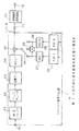
図1は、本実施例の復号画像変換回路31の一例を示す回路構成図である。この図において、表示画像圧縮回路11は、入力ポート10から与えられるI、P、Bピクチャの画像復号化データがマクロブロック単位で与えられるとハフマン符号化方式によって画像圧縮し、IピクチャおよびPピクチャの圧縮データをI・Pピクチャ用圧縮データ格納メモリ回路12に与え、Bピクチャの圧縮データをBピクチャ用圧縮データ格納メモリ回路13に与える。I・Pピクチャ用圧縮データ格納メモリ回路12は、表示画像圧縮回路11から与えられるIピクチャおよびPピクチャの圧縮データを格納し、ラスタスキャンデータに変換するため所定のタイミングで読み出して表示画像伸張回路14に与える。
【0041】
Bピクチャ用圧縮データ格納メモリ回路13は、表示画像圧縮回路11から与えられるBピクチャの圧縮データを格納し、ラスタスキャンデータに変換するため所定のタイミングで読み出して表示画像伸張回路14に与える。表示画像伸張回路14は、I・Pピクチャ用圧縮データ格納メモリ回路12から与えられるIピクチャおよびPピクチャの圧縮データと、Bピクチャ用圧縮データ格納メモリ回路13から与えられるBピクチャの圧縮データとをハフマン符号化に対する画像伸張処理によってラスタスキャンデータにし出力ポート15に出力する。
【0042】
図1の入力ポート10から図8で説明した順番にマクロブロックが入力され、表示画像圧縮回路11に与えられる。この表示画像圧縮回路11では、マクロブロック単位で入力されてきた画像データを16個の水平方向画像列の方向に所定の圧縮比で画像圧縮を行い、Iピクチャ、Pピクチャの場合はI・Pピクチャ用圧縮データ格納メモリ回路12に格納し、Bピクチャの場合はBピクチャ用圧縮データ格納メモリ回路13に格納する。I・Pピクチャ用圧縮データ格納メモリ回路12は、ラスタスキャンデータを形成し得る所定のタイミングで読み出し、Bピクチャ用圧縮データ格納メモリ回路13もラスタスキャンデータを形成し得る所定のタイミングで読み出し、表示画像伸張回路14は、圧縮されているIピクチャ、Pピクチャ、およびBピクチャに対して画像伸張処理を行いラスタスキャンデータを出力する。
【0043】
なお、表示画像圧縮回路11からI・Pピクチャ用圧縮データ格納メモリ回路12、Bピクチャ用圧縮データ格納メモリ回路13に格納するために、表示画像圧縮回路11とメモリ回路12、13との間に、いずれのメモリ回路へ格納させるかを調停する調停回路を設けることも好ましい。
【0044】
また、I・Pピクチャ用圧縮データ格納メモリ回路12、Bピクチャ用圧縮データ格納メモリ回路13の記憶領域を、画像復号化回路19の参照フレーム画像(フレーム画像)を記憶するための1組の大容量ダイナミックRAM のアドレス空間に割り振ることもよい。このときには、参照画像の読み出しのときと、画像圧縮データの格納のときが同時にならないように調停回路を設けるとよい。そして、図1のような構成と工程によってラスタスキャンデータに変換することでメモリ容量を大きく確保することなく、簡単な構成で迅速に変換することができる。
【0045】
次に、表示画像圧縮回路11の具体的な一例の構成を次に述べる。図9は、図1の復号画像変換回路31で使用される表示画像圧縮回路11の構成図であり、ハフマン符号化方式を採用した回路である。この図において、入力段メモリ回路91は、マクロブロック単位に復号されるマクロブロック画素データを一時格納するメモリ回路であり、一つ以上のマクロブロックデータを格納するだけの格納容量とするとよい。
【0046】
そして、入力段メモリ回路91は、格納されているマクロブロック画素データをシーケンサ回路(SEQ )92の制御に従って読み出しレジスタ回路93に与える。このシーケンサ回路92は、本表示画像圧縮回路11内の各構成回路を制御するものであり、入力段メモリ回路91からマクロブロックの画素データをフレームイメージで水平方向に読み出す制御から、バイトアライン回路97から圧縮データを出力させるタイミングの制御までを管理する回路である。
【0047】
レジスタ93は、入力段メモリ回路91からのマクロブロックの画素データを一時格納し、次のレジスタ回路94と差分回路95とに与える。レジスタ回路94は、レジスタ回路93から与えられるマクロブロックの画素データを一時格納し次の差分回路95に与える。レジスタ回路93、94は、フレームイメージで水平方向に隣接する画素データを一時格納する。
【0048】
差分回路95は、レジスタ回路93、94から与えられるマクロブロックの画素データの差分を求め差分値をルックアップテーブル回路(LUT )96に与える。ルックアップテーブル回路96は、発生頻度に応じたハフマン符号テーブルであり、前述の差分回路95から出力される差分値をアドレスとして可変長符号化データを出力しバイトアライン回路(BA)97に与える。このバイトアライン回路97は、ルックアップテーブル回路96から与えられる可変長符号化データをたとえば8ビット単位にまとめる処理を行い、圧縮データとしてバイトデータで出力する。さらに、本表示画像圧縮回路11は、どのようなまとまりで処理され出力されているかを表す付加情報98も付加して出力する。
【0049】
本表示画像圧縮回路11に入力された画像復号化されたマクロブロックは、入力段メモリ回路91に一時格納される。次に、一つのマクロブロックの入力が終了すると、シーケンサ回路92からマクロブロックの読み出し指令が発生し、マクロブロックの左上の画素データから水平方向に16画素連続して読み出される。このときに左端の画素データの符号化時は差分回路95では差分動作が行われず、画素値そのものの値がルックアップテーブル回路96で可変長符号化される。その次のデータはその画素値の左側の値を予測値として差分回路95で差分され、その誤差値が前述と同様にルックアップテーブル回路96で可変長符号化される。
【0050】
マクロブロックの右側のデータが可変長符号化された時点でバイトアライン回路97は、バイトの切れ目までスタッフィング動作を行い圧縮データを出力する。この動作でマクロブロックの最上ラインの圧縮データの転送が終了する。以上のような動作を1マクロブロック当たり16ライン存在するので、1ライン毎に行い合計16回行うことで1マクロブロックの圧縮処理が終了する。
【0051】
なお、画像圧縮の方法としてハフマン符号化を説明したが、ほかに算術符号化や、他のデータ圧縮方式でもよい。
【0052】
このようにして、図1において、表示画像圧縮回路11で水平方向に圧縮されたデータが、I・Pピクチャ用圧縮データ格納メモリ回路12と、Bピクチャ用圧縮データ格納メモリ回路13に転送される。ここで、Bピクチャ用圧縮データ格納メモリ回路13は、マクロブロック書き込み/ラスタ方向読み出しの変換のためだけに用いられるのでなくフレーム構造で送られてきた画像データをインタレースに直すためにも使用される。また、このI・Pピクチャ用圧縮データ格納メモリ回路12は、マクロブロック書き込み/ラスタ方向読み出しおよびフレーム構造で送られてきた画像データをインタレースに直すためだけでなく、前述の図2において処理の順、メディア上の順、表示画像の順を示したように、送られてくる符号化データのピクチャの順と表示の順が異なるためその順番を入れ替えるための遅延バッファとしても使用される。
【0053】
表示画像伸張回路14では、表示のタイミングに合わせて、必要とされる場所の圧縮データをインタレースの順に今現在復号を行っているピクチャタイプから今回表示を行うピクチャがI、P、Bピクチャのいずれかを認識しそれにしたがってI・Pピクチャ用圧縮データ格納メモリ回路12またはBピクチャ用圧縮データ格納メモリ回路13から元の画面順で読み出す処理を行い、前述の表示画像圧縮回路11で行われた処理の逆処理によって画像伸張処理を行い、元に戻されたラスタスキャンデータが出力ポート15から出力される。
【0054】
なお、前述の表示画像圧縮回路11において、水平方向に圧縮する画像データ列の単位を便宜上マクロブロックの大きさと同じ16画素で説明したが、他の画素数でもよい。
【0055】
図10は、表示画像伸張回路14の具体的な一例の回路構成図である。この図10において、切り出し回路100 は、圧縮データおよび付加情報を取り込み、付加されている付加情報から8ビット単位の可変長符号化データを求め逆変換ルックアップテーブル(LUT )回路101 に与える。この逆変換ルックアップテーブル回路101 は、可変長符号化データに対応する差分値に変換し、この差分値を加算回路102 に与える。この加算回路102 は、レジスタ回路103 に一時格納されている画像データと加算し加算結果を再生したマクロブロック画素データとしてレジスタ回路103 とバッファメモリ回路104 とに与える。このバッファメモリ回路104 は、マクロブロック画素データを一時格納し適当なタイミングで読み出してラスタスキャンデータとして出力する。
【0056】
前述の表示画像圧縮回路11および表示画像伸張回路14で行う圧縮処理および伸張処理を行う復号画像変換プログラムを作成することでコンピュータを動作させて同じ機能を実現することができる。
【0057】
以上のように図1に示した復号画像変換回路31の構成および処理工程を用いることでマクロブロック/ラスタスキャン(インタレース、ノンインタレース)などの変換処理を本回路で実現することができるので、従来のようにフレームメモリ回路を3面持つ必要が無くなり、フレームメモリ回路を2面で画像復号処理を行うことができる。これに伴って、フレームメモリ回路は画像復号処理にだけ使用することができるので、従来は1フレーム分の表示時間内に4フレーム分の転送速度が必要であったものが2フレーム分の転送速度で十分となり、従来より1/2のメモリアクセスで画像復号処理を行うことが可能になる。これにより従来よりメモリアクセスのためのメモリバスのビット幅を小さくすることも可能になり、低速アクセスの画像メモリを使用することも可能になり、効率的な処理を実現することができる。
【0058】
また、画像復号処理用に設ける参照フレーム画像を格納するIピクチャおよびPピクチャ用の大容量のダイナミックRAM のメモリ空間の一部に、復号画像変換回路31で使用するIピクチャ・Pピクチャ用圧縮データ格納メモリ回路12およびBピクチャ用圧縮データ格納メモリ回路13の格納領域を割り振る場合、復号画像を圧縮して格納するので、従来のように表示用に1フレーム分のメモリ容量を使用していた方式に比較して転送表示データ量並びにダイナミックRAM 内で占有する記憶容量を少なくすることができる。また、ラスタスキャンデータを読み出すときにフレームイメージで水平方向に圧縮がかけられているので、メモリアクセスに時間がかからず、高速に読み出す効果がある。
【0059】
次に、図11は、復号画像変換回路においてIピクチャおよびPピクチャデータを圧縮せず、Bピクチャだけを圧縮・伸張処理し、IピクチャおよびPピクチャデータはタイミング調整を図り、元の画面順のラスタスキャンデータにするための復号画像変換装置の構成図である(第2の実施例)。
【0060】
この図において、前述の図7の構成回路と同様な部分には、同じ符号を付与しており、同じ構成回路の説明は省略する。そこで、画像復号化回路19A のフレームメモリ回路25、26のIピクチャおよびPピクチャの画像データをスイッチ回路32に与える。スイッチ回路32は、フレームメモリ回路25、26から与えられるIピクチャおよびPピクチャの画像データを択一的に選択出力しFIFO回路33に与える。FIFO回路33は、スイッチ回路32から与えられるIピクチャまたはPピクチャの画像データを一時格納し先入れ先出し(first-in first-out)でラスタスキャンデータを形成し得るタイミングで読み出して出力ポート15に出力する。
【0061】
一方、復号画像変換回路31A は、入力ポート10からBピクチャの画像データを取り込み、このBピクチャ画像データに対して画像圧縮・伸張処理を行いラスタスキャンデータにする。そして、このラスタスキャンデータをFIFO回路33から出力されるIピクチャおよびPピクチャのラスタスキャンデータと共に出力ポート15に出力する。このように、FIFO回路33と復号画像変換回路31A は、出力ポート15から元の画面順のラスタスキャンデータ出力されるように動作する。
【0062】
図12は、図11で使用されている復号画像変換回路31A の一例の回路構成図である(第2の実施例)。この図において、表示画像圧縮回路11は、入力ポート10に与えられるBピクチャ画像データを取り込み、前述の図9のような回路構成で、ハフマン符号化方式を適用して画像圧縮を行い、圧縮データをBピクチャ用圧縮データ格納メモリ回路13に与える。このBピクチャ用圧縮データ格納メモリ回路13は、圧縮されたBピクチャ用圧縮データを格納し、Iピクチャ、Pピクチャとの関係で適当なタイミングで読み出して表示画像伸張回路14に与える。この表示画像伸張回路14は、Bピクチャ用圧縮データ格納メモリ回路13から読み出されたBピクチャ用圧縮データに対して、前述の図10のような構成によって画像伸張処理を行いラスタスキャンデータを得て出力ポート15に出力する。
【0063】
以上のように図12に示した復号画像変換回路31A を用いることでマクロブロック/ラスタスキャン(インタレース、ノンインタレース)などの変換処理などを本回路で実現することができるので、従来のようにフレームメモリ回路を3面持つ必要が無くなり、2面のフレームメモリ回路で画像復号処理を行うことができる。これに伴って、フレームメモリ回路は画像復号処理にだけ使用することができるので、従来は1フレーム分の表示時間内に4フレーム分の転送速度が必要であったものが2フレーム分の転送速度で十分となり、従来より1/2のメモリアクセスで画像復号処理を行うことが可能になる。これにより従来よりメモリアクセスのためのメモリバスのビット幅を小さくすることも可能になり、低速アクセスの画像メモリを使用することも可能になる。
【0064】
また、画像復号処理用に設ける参照フレーム画像を格納するIピクチャおよびPピクチャ用の大容量のダイナミックRAM のメモリ空間の一部に、復号画像変換回路31A で使用するBピクチャ用圧縮データ格納メモリ回路13の格納領域を割り振る場合、復号画像を圧縮して格納するので、従来のように表示用に1フレーム分のメモリ容量を使用していた方式に比較して転送する表示画像データ量並びにダイナミックRAM 内で占有する記憶容量を少なくすることができる。また、ラスタスキャンデータを読み出すときにフレームイメージで水平方向に圧縮がかけられているので、メモリアクセスに時間がかからず、高速に読み出す効果がある。
【0065】
さらに、図11,12 のような構成および処理工程を採ることで、復号画像変換回路31A でIピクチャ、Pピクチャに対する画像圧縮伸張を行う必要がなく、前述の図7の構成に比べて構成が簡単になる。また、画像圧縮および伸張処理にかかる時間も短縮される。さらに、図11および図12の画像復号処理および復号画像変換を行うプログラムを作成し、このプログラムでコンピュータを動作させて実現することもできる。
【0066】
なお、以上の例においては、MPEG2 標準化方式に基づいて符号化された画像データを例にして説明したが、MPEG1 や、フレーム画像をブロック化して送る符号化方式であるITU-T 勧告H.261 (デジタル動画像圧縮)や静止画符号化用のJPEG(Joint Photographic Coding Experts Group )などの符号化方式で符号化された画像データに対しても前述の復号画像変換装置や復号画像変換回路を適用することができる。
【0067】
【発明の効果】
以上述べたように本発明は、画像復号データをフレームイメージで水平方向に連続する画素データ列に分割し、この水平方向画像データ列に対して画像圧縮処理を行い、圧縮したIピクチャおよびPピクチャをI・Pピクチャ用圧縮画像データ格納手段に格納し、圧縮したBピクチャをBピクチャ用圧縮画像データ格納手段に格納し、これらの圧縮したIピクチャおよびPピクチャと圧縮したBピクチャとに対して画像伸張処理を行いラスタスキャンデータにすることで、フレームメモリとしては、画像復号用のI、Pピクチャ用の2つのフレームメモリを持つだけでよく、2つのフレームメモリは、画像復号処理だけに使用して、1フレームの表示時間内に2フレーム分のアクセスでよく、従来に比べて低速で画像復号処理を行うことができる。したがって、フレームメモリへのアクセスを低減し、メモリバス幅を大きくしなくても簡単な回路構成で復号画像を表示用の画像データ列(ラスタスキャンデータ)に変換することができる。
【図面の簡単な説明】
【図1】本発明の実施例のIピクチャ、Pピクチャ、Bピクチャを画像圧縮処理後伸張処理してラスタスキャンデータに変換する復号画像変換回路の構成図である(第1の実施例)。
【図2】従来例のIピクチャ、Bピクチャ、Pピクチャなどの3種類のピクチャの符号化を行う場合の処理の順やメディア上の順や表示画像の順などを示す図である。
【図3】従来例のMPEG2 復号化回路の基本構成図である。
【図4】従来例のMPEG復号画像表示装置の構成図である。
【図5】従来例のIピクチャ、Pピクチャ、Bピクチャ時の復号、表示時のフレームメモリポインタの推移を示す図である。
【図6】従来例のIピクチャ、Pピクチャ、Bピクチャ時の復号、表示時のフレームメモリアクセス回数を示す図である。
【図7】図1の復号画像変換回路と画像復号化回路とを含む復号画像変換装置の構成図である(第1の実施例)。
【図8】本実施例のフレーム画像のマクロブロックの構成図である。
【図9】図1の復号画像変換回路で使用される表示画像圧縮回路の構成図である。
【図10】図1の復号画像変換回路で使用される表示画像伸張回路の構成図である。
【図11】Bピクチャだけを復号画像変換回路で圧縮処理し、IピクチャとPピクチャとは圧縮処理せずラスタスキャンデータにする復号画像変換装置の構成図である(第2の実施例)。
【図12】図11の復号画像変換装置で使用される復号画像変換回路の構成図である。
【符号の説明】
11 表示画像圧縮回路
12 I・Pピクチャ用圧縮データ格納メモリ回路
13 Bピクチャ用圧縮データ格納メモリ回路
14 表示画像伸張回路
19 MPEG2 復号化回路
25、26 フレームメモリ回路
31 復号画像変換回路[0001]
BACKGROUND OF THE INVENTION
The present invention relates to a decoded image conversion circuit and a decoded image conversion device, and more specifically to a computer-readable information recording medium on which a decoded image conversion method and a decoded image conversion program are recorded. Moving Picture Coding Experts Group) 2) Application to circuits and devices for decoding encoded data and displaying images based on standardized systems such as
[0002]
[Prior art]
In the MPEG2 image coding method disclosed in the prior art, one frame image is divided into units called 16 × 16 pixel macroblocks, and redundant information is compressed in space and time. In order to obtain the conversion efficiency, three picture coding types of an I (Intra coded) picture, a P (Predictive coded) picture, and a B (Bidirectly Predictive coded) picture are provided for each frame of the image.
[0003]
An I picture is an intra-frame coding screen, and is coded (intra coding) independently of other screens, and all macroblocks on the screen are intra-coded. By periodically arranging the I picture, it can be used as a random access or an error recovery pointer. However, when the frequency of I pictures increases, the overall coding efficiency decreases. For pictures with scene switching points and poor prediction efficiency, I pictures generally have better encoding efficiency.
[0004]
The P picture is predictive coded from an I picture or P picture located in the past in the past on the forward predictive coding screen. Encoded using forward only prediction.
[0005]
A B picture is a bi-directional predictive coding screen, and predictive coding is performed from a forward, backward, or bi-directional screen using I pictures or P pictures that are positioned in front and back in time, and the prediction direction is in units of macroblocks. It is determined. With the introduction of the B picture, it is possible to accurately perform predictive coding using temporally preceding and succeeding images even in areas where objects disappear or appear, and the coding efficiency is greatly improved. .
[0006]
The combination of these three types of pictures is free, and the encoding apparatus sets them according to the purpose. With respect to the order of encoding, since the I picture and P picture located backward in time are encoded prior to the B picture, for example, as shown in FIG. 2, the original image is B0, B1, I2 , B3, B4, P5, B6, B7, P8, B9, B10, P11, B12, B13, the encoding process is I2, B0, B1, P5, B3, B4, P8, Encoding is performed in the order of B6, B7, P11, B9, B10, P14, B12, B13. Decoding processing is also performed in this order. When outputting an image, the original order B0, B1, I2, B3, B4, P5, B6, B7, P8, B9, B10, P11, B12, The playback images are displayed in the order shown in B13.
[0007]
FIG. 3 is a basic configuration diagram of an MPEG2 decoding circuit that decodes image data encoded based on a conventional MPEG2 standardization system. First, the encoded bit stream is accumulated in the
[0008]
In the case of image data of a P picture, motion compensation processing is performed by
[0009]
The reproduced
[0010]
However, in the actual MPEG2 decoding circuit, the order of outputting the display image data is usually interlaced, so that the macroblock / rasterous conversion is performed after the MPEG2 decoding circuit processed and output in units of macroblocks. Memory is required, and if the picture coding type is a frame structure instead of a field structure, a memory for storing at least 1/2 field image data when outputting in an interlaced manner Is required.
[0011]
Conventionally, in order to solve such a problem, an “image processing system” of the invention described in Japanese Patent Laid-Open No. 7-59084 has been proposed as an example. The “image processing system” described in this document presents a system that processes compressed data that arrives at an image block by a packet.
[0012]
FIG. 4 is a configuration diagram of an MPEG decoded image display device used in the above-described “image processing system”. As shown in this figure, in addition to the frame memory FM1 for I picture and the frame memory FM2 for P picture, a frame memory FM3 for B picture is provided exclusively and has a total of three frame memories FM1, FM2, FM3. Image data can be output in an interlaced order without problems even for macroblock / raster conversion and frame structure pictures.
[0013]
Further, a display method of the “image processing system” of the invention described in the above-mentioned Japanese Patent Application Laid-Open No. 7-59084 will be described. In this system, four image pointers RP, FP, BP, and DP are used to determine the frame memory areas FM1 to FM3 required for the memory controller to access. These are pointers indicating the positions of the current reproduction image, the front image (front image), the rear image (rear image), and the current display image, respectively.
[0014]
FIG. 5 is a diagram showing transition of the frame memory pointer at the time of decoding and display for each picture in the conventional example. In this figure, the order in which the encoded frame images are decoded, the order in which they are displayed, and the value of each image pointer at that time are shown. When the first image IO is decoded, the image is not yet displayed. The reproduced image pointer RP indicates an empty area for storing the image IO, for example, the frame memory FM1.
[0015]
When the image P1 is decoded, the image IO is always displayed. For example, the reproduction image pointer RP indicates the frame memory FM2, and the display image pointer DP indicates the frame memory FM1 in which the image IO exists. Since the predicted image of P1 requires the forward image IO at the time of reproduction, the forward image pointer FP also indicates the frame memory FM1.
[0016]
When the image B2 is decoded, this image B2 is also an image to be displayed. Both the playback image pointer RP and the display image pointer DP indicate the still free area FM3. In decoding, the image B2 requires the front image IO and the rear image P1. At this time, the front image pointer FP and the rear image pointer BP indicate the areas FM1 and FM2, respectively.
[0017]
In order to be able to display an image when it is decoded, an actual display is typically delayed by approximately ½ image. This is done so that when the picture coding type is a frame structure, the decoding process of the image data at the position to be read is always completed before the display is performed even when the display order is interlaced to read every other line. Is the method.
[0018]
When the image B3 is decoded, the image is also displayed. The image B3 requires the images IO and P1 at the time of decoding, so the images IO and P1 use the same frame memories FM1 and FM2 as described above by the front image pointer FP and the rear image pointer BP, and the image B3 is Stored in the frame memory FM3. At this time, the display image pointer DP also indicates FM3 as in the case of the image B2.
[0019]
However, when the image B3 is reproduced in the frame memory FM3 and the image is written, the image B2 stored in the frame memory FM3 is displayed. At this time, when the displayed image B2 is about to be overwritten by the reproduced image B3, the
[0020]
When the image P4 is decoded, the image P1 is always displayed. This image P4 is stored in the frame memory FM1, which becomes free thereafter. At this time, the reproduction image pointer DP indicates the frame memory FM2 in which the image P1 is stored. The image P4 requires the forward image P1 at the time of decoding. The forward image pointer FP indicates the frame memory FM2.
[0021]
In FIG. 5, when an image B5 is decoded, this image is always displayed. The image B5 is stored in the frame memory FM3 to be freed. At this time, the reproduction image pointer RP and the display image DP pointer indicate the frame memory FM3. The image B5 requires a front image P1 and a rear image P4 that has already been decoded. The forward image pointer P4 and the backward image pointer BP indicate the frame memories FM2 and FM1, respectively.
[0022]
[Problems to be solved by the invention]
However, in the conventional image processing system as described above, as shown in FIG. 6, in order to decode a B picture, images for a maximum of two frames (forward prediction screen and backward prediction screen) are used as reference images within one frame time. One frame is stored to store the read and reproduced decoded image, and one frame image is read for display. As described above, in order to perform image decoding and decoded image conversion (display), a conventional image processing system requires a frame memory bus capable of transferring images of four frames within one frame time. In FIG. 4 described above, the frame memory bus MBUS corresponds to this frame memory bus. For this reason, in order to access the frame memory at high speed, it is necessary to increase the bus width (bit width) of the frame memory or to use a frame memory that can be accessed at high speed, resulting in an expensive system.
[0023]
For this reason, it is possible to reduce the access to the frame memory and convert the decoded image data into a display image data string (raster scan data) with a simple circuit configuration without increasing the memory bus width. There has been a demand for a computer-readable information recording medium on which a decoded image conversion circuit, a decoded image conversion device, a decoded image conversion method, and a decoded image conversion program are recorded.
[0024]
[Means for Solving the Problems]
Therefore, according to the present invention, decoding is performed on encoded image data that has been encoded by dividing a frame image obtained by rearranging the screen according to the picture type into a plurality of small area image data. The decoded image conversion circuit that inputs the decoded image data obtained by the above and converts the raster image data into raster scan data for each small area image data, and continuously outputs the decoded image data corresponding to the small area image data in the horizontal direction in the frame image. An image compression unit that divides the image data into horizontal pixel data strings and performs image compression processing on the horizontal image data strings to obtain compressed image data, and among the compressed image data obtained by the image compression means, the picture type is Intraframe coding / forward prediction storing compressed image data of the intraframe coding screen (I picture) and the forward prediction coding screen (P picture). Compressed picture data storage means for coded pictures, and a bidirectional predictive coded picture for storing compressed picture data having a picture type of a bidirectional predictive coding screen (B picture) among the compressed picture data obtained by the picture compressing means Compressed image data storage means, compressed image data stored in intra-frame / forward prediction encoded picture compressed image data storage means, and bidirectional predictive encoded picture compressed image data storage means Image expansion means for sequentially capturing and performing image expansion processing to obtain raster scan data.
[0025]
By adopting such a configuration, it is possible to perform decompression processing while taking the timing of the compressed I picture, P picture and B picture of the decoded image data, and convert it into raster scan data. The compressed image data storage means for forward predictive coded pictures and the compressed image data storage means for bidirectional predictive coded pictures store image data obtained by compressing I pictures, P pictures, and B pictures, and do not require a large storage capacity. Can be converted with a very simple configuration.
[0026]
Further, according to the present invention, the image data is obtained by rearranging the screens according to the picture type, taking in the encoded image data encoded by quantization and orthogonal transformation, and performing inverse quantization and inverse orthogonal transformation. When the inverse transforming means for generating and outputting, the memory means including two storage areas for storing the decoded picture data of the picture type I picture and P picture, and when the image data of the I picture is output from the inverse transforming means, This image data is output as image decoded data and stored in the storage area of the memory means. When image data of P picture is output, the image decoded data of I picture or P picture located in front of this P picture is stored in the memory. The image decoded data is obtained and output by reading out from one storage area of the means and adding it to the image data, and the When the image data of the picture type B picture is output, the image decoding data is read from the two storage areas of the memory means, and the average value is calculated. An adder that obtains and outputs decoded image data by adding to the data, and the decoded image output from the adder is divided into a horizontal pixel data sequence that is continuous in the horizontal direction in the frame image, water Image compression means for obtaining compressed image data by performing image compression processing on the horizontal direction image data sequence, and compressed image data having picture types of I picture and P picture among the compressed image data obtained by the image compression means Compressed image data storage means for storing intra-frame encoding / forward prediction encoded picture to be stored, and bi-directional predictive code for storing compressed image data of picture type B among the compressed image data obtained by the image compression means Compressed image data storage means for compressed pictures, compressed image data storage means for intra-frame / forward prediction encoded pictures, and compressed image data storage means for bidirectional predictive encoded pictures And image expansion means for obtaining raster scan data by performing image expansion processing.
[0027]
Furthermore, according to the present invention, decoding is performed on encoded image data obtained by dividing a frame image obtained by rearranging a screen according to a picture type into image data of a plurality of small areas. The decoded image conversion method for converting the small area image data into raster scan data based on the decoded image data obtained by the above method is a method in which the decoded image data corresponding to the small area image data is horizontally converted into a frame image in the horizontal direction. An image compression step of dividing the horizontal pixel data sequence and performing image compression processing on the horizontal image data sequence to obtain compressed image data, and among the compressed image data obtained in the image compression step, the picture type is I A frame for storing compressed image data of a picture and a P picture in compressed image data storage means for intra-frame / forward prediction encoded pictures Compressed image data for compressed picture data of the picture type B picture among the compressed image data obtained in the compressed image data storage process for the inner-coded and forward-predictive coded pictures and the image compression process. Compressed image data storage step for bi-predictive coded pictures to be stored in data storage means, compressed image data storage means for intra-frame coding / forward predictive coded pictures, and compressed image data storage means for bi-directional predictive coded pictures An image expansion step of reading the compressed image data stored in the original screen in the order of the original screen and performing image expansion processing to obtain the raster scan data.
[0028]
Furthermore, according to the present invention, decoding is performed on encoded image data obtained by encoding a frame image obtained by rearranging the screens according to the picture type into a plurality of small area image data. A computer-readable information recording medium on which a decoded image conversion program for converting raster image data into raster scan data for each small area image data is recorded on the basis of the decoded image data thus obtained is an image corresponding to the small area image data. The decoded data is divided into a horizontal pixel data sequence that is continuous in the horizontal direction in the frame image, and an image compression procedure for obtaining compressed image data by performing image compression processing on the horizontal image data sequence, and an image compression procedure. In-frame coding / compressed compressed image data with picture types of I and P pictures Of the compressed image data storage procedure for intra-frame encoding / forward prediction encoded picture to be stored in the compressed image data storage means for predictive encoded pictures and the compressed image data obtained by the image compression procedure, the picture type is B picture Of compressed image data for bi-predictive coded pictures for storing the compressed image data in the compressed image data storage means for bi-predictive coded pictures, and storage of compressed image data for intra-frame coding and forward predictive coded pictures And an image decompression procedure for reading compressed image data stored in the bi-predictive encoded picture compressed image data storage means in the order of the original screen and performing image decompression processing to obtain raster scan data.
[0029]
By adopting the configuration as described above, in order to convert the image decoding data for each small area image data into raster scan data, the image decoding data is divided into a pixel data sequence that is continuous in the horizontal direction in the frame image. Image compression processing is performed on the horizontal image data sequence, the compressed I picture and P picture are stored in the compressed image data storage means for I / P picture, and the compressed B picture is stored in the compressed image data storage means for B picture By storing and compressing these compressed I and P pictures and the compressed B picture into raster scan data, the decoded image conversion apparatus has conventional I, P, B There is no need to have a three-frame frame memory for pictures. As the frame memory, it is only necessary to have a two-frame frame memory for I and P pictures for image decoding. In the decoded image conversion, it is only necessary to have a storage means capable of storing the compressed data.
[0030]
Therefore, the intra-frame encoded image memory means (for example, the frame memory) and the inter-frame forward prediction encoded image memory means (for example, the frame memory) are used only for the image decoding process and within the display time of one frame. In other words, the access for two frames is sufficient, and the image decoding process can be performed at a lower speed than the conventional method of FIG.
[0031]
DETAILED DESCRIPTION OF THE INVENTION
Next, preferred embodiments of the present invention will be described with reference to the drawings. First, FIG. 7 is a configuration diagram of a decoded image conversion apparatus including the
[0032]
The
[0033]
The
[0034]
The decoded
[0035]
In FIG. 7, a bit stream of encoded image data is input to the
[0036]
When the image data output from the
[0037]
Thus, when decoding a bit stream of image encoded data based on MPEG2, the decoded
[0038]
First, FIG. 8 is a configuration diagram of a macroblock of a frame image according to the present embodiment. In this figure, for example, if the size of the frame image is 720 pixels in the horizontal direction and 480 pixels in the vertical direction, there are 1350 macroblocks composed of 16 x 16 pixels, and transfer when encoding is performed. The order is raster scan order, starting from the upper left macroblock M1 of the image, and transferring from left to right to the right macroblock M45 of the image, the leftmost macroblock M46 is transferred one step down, and the left The operation of moving from right to right is repeated, and finally the macro block M1350 at the lower right is transferred and the process ends.
[0039]
The above-described image decoding process of the
[0040]
FIG. 1 is a circuit configuration diagram showing an example of the decoded
[0041]
The B-picture compressed data
[0042]
Macroblocks are input from the
[0043]
In order to store from the display
[0044]
Further, the storage areas of the compressed data
[0045]
Next, a specific example configuration of the display
[0046]
The input
[0047]
The
[0048]
The
[0049]
The image-decoded macroblock input to the display
[0050]
When the data on the right side of the macroblock is variable-length encoded, the
[0051]
Although Huffman coding has been described as an image compression method, arithmetic coding or other data compression methods may be used.
[0052]
In this way, in FIG. 1, the data compressed in the horizontal direction by the display
[0053]
In the display
[0054]
In the display
[0055]
FIG. 10 is a circuit configuration diagram of a specific example of the display
[0056]
The same function can be realized by operating a computer by creating a decoded image conversion program for performing compression processing and decompression processing performed by the display
[0057]
As described above, by using the configuration and processing steps of the decoded
[0058]
Also, compressed I-picture / P-picture data used in the decoded
[0059]
Next, FIG. 11 shows that the decoded picture conversion circuit does not compress the I picture and P picture data, but compresses / decompresses only the B picture, adjusts the timing of the I picture and P picture data, It is a block diagram of the decoding image conversion apparatus for making it raster scan data (2nd Example).
[0060]
In this figure, the same reference numerals are given to the same parts as those of the above-described constituent circuit of FIG. Therefore, the image data of the I picture and P picture of the
[0061]
On the other hand, the decoded
[0062]
FIG. 12 is a circuit configuration diagram of an example of the decoded
[0063]
As described above, by using the decoded
[0064]
In addition, a compressed data storage memory circuit for B pictures used in the decoded
[0065]
Further, by adopting the configuration and processing steps as shown in FIGS. 11 and 12, it is not necessary to perform image compression / decompression for the I picture and P picture in the decoded
[0066]
In the above example, image data encoded based on the MPEG2 standardization method has been described as an example. However, MPEG1 and ITU-T recommendation H.261, which is an encoding method for sending frame images in blocks, are described. The above-described decoded image conversion device and decoded image conversion circuit are also applied to image data encoded by encoding methods such as (Digital Video Compression) and JPEG (Joint Photographic Coding Experts Group) for still image encoding. can do.
[0067]
【The invention's effect】
As described above, the present invention divides the decoded image data into pixel data sequences that are continuous in the horizontal direction in the frame image, performs image compression processing on the horizontal image data sequences, and compresses the compressed I picture and P picture. Are stored in the compressed image data storage means for I / P pictures, the compressed B pictures are stored in the compressed image data storage means for B pictures, and the compressed I and P pictures and the compressed B pictures are By performing image expansion processing and raster scan data, the frame memory only needs to have two frame memories for I and P pictures for image decoding, and the two frame memories are used only for image decoding processing. Thus, it is possible to access two frames within the display time of one frame, and image decoding processing can be performed at a lower speed than in the past. That. Therefore, it is possible to reduce the access to the frame memory and convert the decoded image into a display image data string (raster scan data) with a simple circuit configuration without increasing the memory bus width.
[Brief description of the drawings]
FIG. 1 is a configuration diagram of a decoded image conversion circuit that converts an I picture, a P picture, and a B picture according to an embodiment of the present invention into raster scan data by performing decompression processing after image compression processing (first embodiment).
FIG. 2 is a diagram illustrating a processing order, a media order, a display image order, and the like when encoding three types of pictures such as an I picture, a B picture, and a P picture of a conventional example.
FIG. 3 is a basic configuration diagram of a conventional MPEG2 decoding circuit;
FIG. 4 is a configuration diagram of a conventional MPEG decoded image display device.
FIG. 5 is a diagram illustrating transition of a frame memory pointer during decoding and display in a conventional example of I picture, P picture, and B picture.
FIG. 6 is a diagram illustrating the number of times frame memory is accessed during decoding and display for a conventional I picture, P picture, and B picture.
7 is a block diagram of a decoded image conversion apparatus including the decoded image conversion circuit and the image decoding circuit in FIG. 1 (first embodiment).
FIG. 8 is a configuration diagram of a macroblock of a frame image according to the present embodiment.
9 is a configuration diagram of a display image compression circuit used in the decoded image conversion circuit of FIG. 1. FIG.
10 is a configuration diagram of a display image expansion circuit used in the decoded image conversion circuit of FIG. 1. FIG.
FIG. 11 is a configuration diagram of a decoded image conversion apparatus in which only a B picture is compressed by a decoded image conversion circuit, and an I picture and a P picture are converted into raster scan data without being compressed (second embodiment).
12 is a configuration diagram of a decoded image conversion circuit used in the decoded image conversion apparatus in FIG. 11. FIG.
[Explanation of symbols]
11 Display image compression circuit
12 Compressed data storage memory circuit for I / P picture
13 B picture compressed data storage memory circuit
14 Display image expansion circuit
19 MPEG2 decoding circuit
25, 26 frame memory circuit
31 Decoded image conversion circuit
Claims (15)
前記小エリアの画像データに対応した前記画像復号データをフレームイメージで水平方向に連続する水平方向画素データ列に分割し、該水平方向画像データ列に対して画像圧縮処理を行って圧縮画像データを得る画像圧縮手段と、
該画像圧縮手段で得られた圧縮画像データの内、ピクチャタイプがフレーム内符号化画面および前方向予測符号化画面の圧縮画像データを格納するフレーム内符号化・前方向予測符号化ピクチャ用圧縮画像データ格納手段と、
前記画像圧縮手段で得られた圧縮画像データの内、ピクチャタイプが双方向予測符号化画面の圧縮画像データを格納する双方向予測符号化ピクチャ用圧縮画像データ格納手段と、
前記フレーム内符号化・前方向予測符号化ピクチャ用圧縮画像データ格納手段および前記双方向予測符号化ピクチャ用圧縮画像データ格納手段に格納されている圧縮画像データを元の画面順に取り込み、画像伸張処理を行い前記ラスタスキャンデータを得る画像伸張手段とを含むことを特徴とする復号画像変換回路。Decoded image data obtained by performing decoding on encoded image data obtained by dividing a frame image obtained by rearranging the screens according to the picture type into a plurality of small area image data. In the decoded image conversion circuit that inputs and converts the image data of the small area into raster scan data, the circuit includes:
The decoded image data corresponding to the image data of the small area is divided into a horizontal pixel data sequence that is continuous in a horizontal direction in a frame image, and an image compression process is performed on the horizontal image data sequence to obtain compressed image data. Image compression means to obtain;
Of the compressed image data obtained by the image compression means, the compressed image for the intra-frame / forward prediction encoded picture that stores the compressed image data of which the picture type is the intra-frame encoding screen and the forward prediction encoding screen Data storage means;
Among the compressed image data obtained by the image compression means, the compressed image data storage means for bi-directional predictive coded pictures for storing the compressed image data whose picture type is the bi-directional predictive coding screen;
The compressed image data stored in the compressed image data storage means for the intra-frame encoded / forward prediction encoded picture and the compressed image data storage means for the bidirectional predictive encoded picture are fetched in the order of the original screen, and image expansion processing is performed. And a decompressed image conversion means for obtaining the raster scan data.
前記水平方向画像データ列の隣接する画素間の差分値を求める差分値算出部と、
該差分値の発生頻度に応じた可変長符号を出力する変換部と、
該可変長符号を所定のビット数を単位としたバイトにまとめて圧縮画像データとして出力する圧縮画像データ出力部とを含むことを特徴とする復号画像変換回路。The decoded image conversion circuit according to claim 1, wherein the image compression means includes:
A difference value calculation unit for obtaining a difference value between adjacent pixels of the horizontal image data sequence;
A converter that outputs a variable-length code according to the frequency of occurrence of the difference value;
A decoded image conversion circuit comprising: a compressed image data output unit that outputs the variable length code as compressed image data in a unit of bytes with a predetermined number of bits as a unit.
前記水平方向画像データ列の隣接する画素間の差分値を求める差分値算出部と、
該差分値の発生頻度に応じた可変長符号を出力する変換部と、
該可変長符号を所定のビット数を単位としたバイトにまとめて圧縮画像データとして出力する圧縮画像データ出力部とを含み、
前記画像伸張手段は、
前記フレーム内符号化・前方向予測符号化ピクチャ用圧縮画像データ格納手段および前記双方向予測符号化ピクチャ用圧縮画像データ格納手段に格納されている画像圧縮データを取り込んで前記可変長符号を検出し、該可変長符号に対応する隣接画素間の差分値を得る逆変換部と、
該差分値から加算演算によって水平方向画像データ列を求め、ラスタスキャンデータを出力する画像伸張データ出力部とを含むことを特徴とする復号画像変換回路。The decoded image conversion circuit according to claim 1, wherein the image compression means includes:
A difference value calculation unit for obtaining a difference value between adjacent pixels of the horizontal image data sequence;
A converter that outputs a variable-length code according to the frequency of occurrence of the difference value;
And a compressed image data output unit for outputting as the compressed image data together in bytes the variable length code in units of a predetermined number of bits,
The image expansion means includes
The variable length code is detected by taking in the compressed image data stored in the compressed image data storing means for the intra-frame encoded / forward predictive encoded picture and the compressed image data storing means for the bidirectional predictive encoded picture. , An inverse transform unit for obtaining a difference value between adjacent pixels corresponding to the variable length code;
A decoded image conversion circuit comprising: an image expansion data output unit that obtains a horizontal image data string from the difference value by an addition operation and outputs raster scan data.
ピクチャタイプがフレーム内符号化画面および前方向予測符号化画面の画像復号データを格納する2つの格納領域を含むメモリ手段と、
前記逆変換手段からフレーム内符号化画面の画像データが出力されたとき、該画像データを画像復号データとして出力すると共に前記メモリ手段の格納領域に格納し、前方向予測符号化画面の画像データが出力されたとき、該前方向予測符号化画面の前方に位置するフレーム内符号化画面または前方向予測符号化画面の画像復号データを前記メモリ手段の一方の格納領域から読み出して前記画像データに加算することにより画像復号データを得て出力すると共に前記メモリ手段の他方の格納領域に格納し、ピクチャタイプが双方向予測符号化画面の画像データが出力されたとき、前記メモリ手段の2つの格納領域から画像復号データを読み出して平均値を算出し、該平均値を前記画像データに加算することにより画像復号データを得て出力する加算手段と、
前記加算手段から出力される画像復号データをフレームイメージで水平方向に連続する水平方向画素データ列に分割し、該水平方向画像データ列に対して画像圧縮処理を行って圧縮画像データを得る画像圧縮手段と、
該画像圧縮手段で得られた圧縮画像データの内、ピクチャタイプがフレーム内符号化画面および前方向予測符号化画面の圧縮画像データを格納するフレーム内符号化・前方向予測符号化ピクチャ用圧縮画像データ格納手段と、
前記画像圧縮手段で得られた圧縮画像データの内、ピクチャタイプが双方向予測符号化画面の圧縮画像データを格納する双方向予測符号化ピクチャ用圧縮画像データ格納手段と、
前記フレーム内符号化・前方向予測符号化ピクチャ用圧縮画像データ格納手段および前記双方向予測符号化ピクチャ用圧縮画像データ格納手段に格納されている圧縮画像データを元の画面順に取り込み、画像伸張処理を行いラスタスキャンデータを得る画像伸張手段とを含むことを特徴とする復号画像変換装置。Inverse transforming means for fetching image encoded data encoded by quantization and orthogonal transform after rearranging the screen according to the picture type, and generating and outputting image data by performing inverse quantization and inverse orthogonal transform When,
Memory means including two storage areas for storing the image decoding data of the picture type of the intra-frame coding screen and the forward prediction coding screen;
When the image data of the intra-frame encoded screen is output from the inverse transform unit, the image data is output as image decoded data and stored in the storage area of the memory unit, and the image data of the forward predictive encoded screen is When output, the image decoding data of the intra-frame coding screen or the forward prediction coding screen located in front of the forward prediction coding screen is read from one storage area of the memory means and added to the image data To obtain and output the decoded image data and store it in the other storage area of the memory means, and when the picture data of the bidirectional predictive coding screen is output as the picture type, the two storage areas of the memory means The decoded image data is read out from the image data, an average value is calculated, and the average value is added to the image data to obtain and output the decoded image data. And adding means,
Image compression data obtained by dividing the decoded image data output from the adding means into a horizontal pixel data sequence continuous in the horizontal direction in a frame image, and performing compressed image processing on the horizontal image data sequence Means,
Of the compressed image data obtained by the image compression means, the compressed image for the intra-frame / forward prediction encoded picture that stores the compressed image data of which the picture type is the intra-frame encoding screen and the forward prediction encoding screen Data storage means;
Among the compressed image data obtained by the image compression means, the compressed image data storage means for bi-directional predictive coded pictures for storing the compressed image data whose picture type is the bi-directional predictive coding screen;
The compressed image data stored in the compressed image data storage means for the intra-frame encoded / forward prediction encoded picture and the compressed image data storage means for the bidirectional predictive encoded picture are fetched in the order of the original screen, and image expansion processing is performed. decoded image conversion apparatus characterized by comprising an image expansion means for obtaining a raster scan data performed.
ピクチャタイプがフレーム内符号化画面および前方向予測符号化画面の画像復号データを格納する2つの格納領域を含むメモリ手段と、
前記逆変換手段からフレーム内符号化画面の画像データが出力されたとき、該画像データを画像復号データとして前記メモリ手段の格納領域に格納し、前方向予測符号化画面の画像データが出力されたとき、該前方向予測符号化画面の前方に位置するフレーム内符号化画面または前方向予測符号化画面の画像復号データを前記メモリ手段の一方の格納領域から読み出して前記画像データに加算することにより画像復号データを得て前記メモリ手段の他方の格納領域に格納し、ピクチャタイプが双方向予測符号化画面の画像データが出力されたとき、前記メモリ手段の2つの格納領域から画像復号データを読み出して平均値を算出し、該平均値を前記画像データに加算することにより画像復号データを得て出力する加算手段と、
前記メモリ手段の格納領域に格納されているフレーム内符号化画面または前方向予測符号化画面の画像復号データを選択して読み出し、一時記憶の後ラスタスキャンデータを形成し得るタイミングで読み出してラスタスキャンデータにするタイミング調整手段と、
前記加算手段から出力される双方向予測符号化画面の復号データをラスタスキャンデータにする復号画像変換手段とを含むことを特徴とする復号画像変換装置。Inverse transforming means for fetching image encoded data encoded by quantization and orthogonal transform after rearranging the screen according to the picture type, and generating and outputting image data by performing inverse quantization and inverse orthogonal transform When,
Memory means including two storage areas for storing the image decoding data of the picture type of the intra-frame coding screen and the forward prediction coding screen;
When the image data of the intra-frame coding screen is output from the inverse transform unit, the image data is stored as the image decoding data in the storage area of the memory unit, and the image data of the forward predictive coding screen is output The image decoding data of the intra-frame coding screen or the forward prediction coding screen located in front of the forward prediction coding screen is read from one storage area of the memory means and added to the image data The decoded image data is obtained and stored in the other storage area of the memory means, and when the picture data of the bidirectional predictive encoding screen is output, the decoded image data is read from the two storage areas of the memory means. Calculating an average value and adding the average value to the image data to obtain and output decoded image data; and
Select and read out the image decoding data of the intra-frame encoding screen or the forward prediction encoding screen stored in the storage area of the memory means, read out the raster scan data at a timing capable of forming raster scan data after temporary storage, and perform raster scan Timing adjustment means to make data,
A decoded image conversion apparatus comprising: decoded image conversion means for converting the decoded data of the bidirectional predictive encoding screen output from the addition means into raster scan data.
前記加算手段から出力される双方向予測符号化画面の復号データに対して画像圧縮を行う画像圧縮部と、
該画像圧縮部で画像圧縮された画像データを格納する圧縮画像データ格納部と、
該圧縮画像データ格納部に格納されている圧縮画像データを取り込み、画像伸張処理を行いラスタスキャンデータにする画像伸張部とを含むことを特徴とする復号画像変換装置。The decoded image conversion apparatus according to claim 6, wherein the decoded image conversion means includes:
An image compression unit that performs image compression on the decoded data of the bidirectional predictive encoding screen output from the adding unit;
A compressed image data storage unit for storing the image data compressed by the image compression unit;
A decoded image conversion apparatus comprising: an image expansion unit that takes in compressed image data stored in the compressed image data storage unit and performs image expansion processing to obtain raster scan data.
前記復号画像変換手段の圧縮画像データ格納部の格納領域と前記メモリ手段の格納領域とを同一のメモリ空間に割り振ることを特徴とする復号画像変換装置。The decoded image conversion apparatus according to claim 8, wherein
Decoded image conversion apparatus characterized by allocating a storage area of the compressed image data storage unit of the decoded image converting means and storage area of said memory means in the same memory space.
前記小エリアの画像データに対応した前記画像復号データをフレームイメージで水平方向に連続する水平方向画素データ列に分割し、該水平方向画像データ列に対して画像圧縮処理を行って圧縮画像データを得る画像圧縮工程と、
該画像圧縮工程で得られた圧縮画像データの内、ピクチャタイプがフレーム内符号化画面および前方向予測符号化画面の圧縮画像データを前記第1の格納手段に格納するフレーム内符号化・前方向予測符号化ピクチャ用圧縮画像データ格納工程と、
前記画像圧縮工程で得られた圧縮画像データの内、ピクチャタイプが双方向予測符号化画面の圧縮画像データを前記第2の格納手段に格納する双方向予測符号化ピクチャ用圧縮画像データ格納工程と、
前記第1の格納手段および前記第2の格納手段に格納されている圧縮画像データを元の画面順に読み出し、画像伸張処理を行って前記ラスタスキャンデータを得る画像伸張工程とを含むことを特徴とする復号画像変換方法。 A first storage means for storing compressed image data of which the picture type is an intra-frame coding screen and a forward prediction coding screen of the compressed image data; and the picture type of the compressed image data is a bidirectional prediction code A frame image obtained by rearranging the screens according to the picture type is divided into a plurality of small area image data using a decoded image conversion circuit having second storage means for storing compressed image data of the converted screen. In a decoded image conversion method for converting raster image data into raster scan data for each image data of the small area based on image decoded data obtained by decoding the encoded image encoded data, the method Is
The decoded image data corresponding to the image data of the small area is divided into a horizontal pixel data sequence that is continuous in a horizontal direction in a frame image, and an image compression process is performed on the horizontal image data sequence to obtain compressed image data. An image compression process to obtain;
Of the compressed image data obtained in the image compression step, the intra-frame coding / forward direction storing compressed image data of which the picture type is an intra-frame coding screen and a forward prediction coding screen in the first storage means Storing compressed image data for predictive encoded pictures;
A compressed image data storage step for bidirectional predictive coded pictures that stores, in the second storage means, compressed image data having a picture type of bidirectional predictive coded screen among the compressed image data obtained in the image compressing step; ,
An image decompression step of reading the compressed image data stored in the first storage means and the second storage means in the order of the original screen and performing image decompression processing to obtain the raster scan data. Decoded image conversion method.
前記ピクチャタイプに応じて画面を並べ替えた後量子化および直交変換により符号化された画像符号化データを取り込み、逆量子化および逆直交変換を行い画像復号データを得る逆変換工程と、
ピクチャタイプがフレーム内符号化画面および前方向予測符号化画面の画像復号データを前記メモリ手段の2つの格納領域に格納する格納工程と、
前記逆変換工程でフレーム内符号化画面の画像データが得られたとき、該画像データを画像復号データとして出力すると共に前記メモリ手段の格納領域に格納し、前方向予測符号化画面の画像データが得られたとき、該前方向予測符号化画面の前方に位置するフレーム内符号化画面または前方向予測符号化画面の画像復号データを前記メモリ手段の一方の格納領域から読み出して前記画像データに加算することにより画像復号データを得て出力すると共に前記メモリ手段の他方の格納領域に格納し、ピクチャタイプが双方向予測符号化画面の画像データが得られたとき、前記メモリ手段の2つの格納領域から画像復号データを読み出して平均値を算出し、該平均値を前記画像データに加算することにより画像復号データを得て出力する加算工程と、
該加算工程で得られた画像復号データをフレームイメージで水平方向に連続する水平方向画素データ列に分割し、該水平方向画像データ列に対して画像圧縮処理を行って圧縮画像データを得る画像圧縮工程と、
該画像圧縮工程で得られた圧縮画像データの内、ピクチャタイプがフレーム内符号化画面および前方向予測符号化画面の圧縮画像データを前記第1の格納手段に格納するフレーム内符号化・前方向予測符号化ピクチャ用圧縮画像データ格納工程と、
前記画像圧縮工程で得られた圧縮画像データの内、ピクチャタイプが双方向予測符号化画面の圧縮画像データを前記第2の格納手段に格納する双方向予測符号化ピクチャ用圧縮画像データ格納工程と、
前記第1の格納手段および前記第2の格納手段に格納されている圧縮画像データを元の画面順に取り込み、画像伸張処理を行ってラスタスキャンデータを得る画像伸張工程とを含むことを特徴とする復号画像変換方法。 Memory means including two storage areas for storing image decoding data of a picture type of an intra-frame coding screen and a forward prediction coding screen, and among the compressed image data, a picture type is an intra-frame coding screen and a forward direction Decoding having first storage means for storing compressed image data of a predictive coding screen, and second storage means for storing compressed image data of a picture type having a bidirectional predictive coding screen among the compressed image data In a decoded image conversion method using an image conversion apparatus, the method includes:
An inverse transform step of capturing image encoded data encoded by quantization and orthogonal transform after rearranging the screens according to the picture type, and performing inverse quantization and inverse orthogonal transform to obtain image decoded data;
A storing step of picture type stores the decoded video data in the coded frame and the forward predictive coded frame frame into two storage areas of said memory means,
When the image data of the intra-frame encoded screen is obtained in the inverse transform step, the image data is output as image decoded data and stored in the storage area of the memory means, and the image data of the forward predictive encoded screen is When obtained, the image decoding data of the intra-frame coding screen or the forward prediction coding screen located in front of the forward prediction coding screen is read from one storage area of the memory means and added to the image data To obtain and output the decoded image data and store it in the other storage area of the memory means, and when the picture data of the bidirectional predictive coding screen is obtained as the picture type, the two storage areas of the memory means The image decoding data is read out from the image data, an average value is calculated, and the average value is added to the image data to obtain and output the image decoding data. And,
Image compression obtained by dividing the decoded image data obtained in the adding step into a horizontal pixel data sequence continuous in the horizontal direction in a frame image, and performing compressed image data on the horizontal image data sequence Process,
Of the compressed image data obtained in the image compression step, the intra-frame coding / forward direction storing compressed image data of which the picture type is an intra-frame coding screen and a forward prediction coding screen in the first storage means Storing compressed image data for predictive encoded pictures;
A compressed image data storage step for bidirectional predictive coded pictures that stores, in the second storage means, compressed image data having a picture type of bidirectional predictive coded screen among the compressed image data obtained in the image compressing step; ,
An image decompression step of fetching compressed image data stored in the first storage means and the second storage means in the order of the original screen and performing image decompression processing to obtain raster scan data. Decoded image conversion method.
前記ピクチャタイプに応じて画面を並べ替えた後量子化および直交変換により符号化された画像符号化データを取り込み、逆量子化および逆直交変換を行い画像復号データを得る逆変換工程と、
ピクチャタイプがフレーム内符号化画面および前方向予測符号化画面の画像復号データを前記メモリ手段の2つの格納領域に格納する格納工程と、
前記逆変換工程でフレーム内符号化画面の画像データが得られたとき、該画像データを画像復号データとして前記メモリ手段の格納領域に格納し、前方向予測符号化画面の画像データが得られたとき、該前方向予測符号化画面の前方に位置するフレーム内符号化画面または前方向予測符号化画面の画像復号データを前記メモリ手段の一方の格納領域から読み出して前記画像データに加算することにより画像復号データを得て前記メモリ手段の他方の格納領域に格納し、ピクチャタイプが双方向予測符号化画面の画像データが得られたとき、前記メモリ手段の2つの格納領域から画像復号データを読み出して平均値を算出し、該平均値を前記画像データに加算することにより画像復号データを得て出力する加算工程と、
前記メモリ手段の格納領域に格納されているフレーム内符号化画面または前方向予測符号化画面の画像復号データを選択して読み出し、一時記憶の後ラスタスキャンデータを形成し得るタイミングで読み出してラスタスキャンデータにするタイミング調整工程と、
前記加算工程で得られた双方向予測符号化画面の復号データをラスタスキャンデータにする復号画像変換工程とを含むことを特徴とする復号画像変換方法。In a decoded image conversion method using a decoded image conversion apparatus having memory means including two storage areas for storing image decoded data of picture types whose intra-frame encoded screen and forward prediction encoded screen are stored,
An inverse transform step of capturing image encoded data encoded by quantization and orthogonal transform after rearranging the screens according to the picture type, and performing inverse quantization and inverse orthogonal transform to obtain image decoded data;
A storing step of picture type stores the decoded video data in the coded frame and the forward predictive coded frame frame into two storage areas of said memory means,
When the image data of the intra-frame coding screen is obtained in the inverse transforming step, the image data is stored in the storage area of the memory means as the image decoding data, and the image data of the forward prediction coding screen is obtained. The image decoding data of the intra-frame coding screen or the forward prediction coding screen located in front of the forward prediction coding screen is read from one storage area of the memory means and added to the image data The decoded image data is obtained and stored in the other storage area of the memory means. When the picture data of the bidirectional predictive encoding screen is obtained, the decoded image data is read from the two storage areas of the memory means. Calculating an average value and adding the average value to the image data to obtain and output decoded image data; and
Select and read out the image decoding data of the intra-frame encoding screen or the forward prediction encoding screen stored in the storage area of the memory means, read out the raster scan data at a timing capable of forming raster scan data after temporary storage, and perform raster scan The timing adjustment process to make data,
And a decoded image conversion step of converting the decoded data of the bidirectional predictive encoding screen obtained in the adding step into raster scan data.
前記小エリアの画像データに対応した前記画像復号データをフレームイメージで水平方向に連続する水平方向画素データ列に分割し、該水平方向画像データ列に対して画像圧縮処理を行って圧縮画像データを得る画像圧縮手順と、
該画像圧縮手順で得られた圧縮画像データの内、ピクチャタイプがフレーム内符号化画面および前方向予測符号化画面の圧縮画像データを前記第1の格納手段に格納するフレーム内符号化・前方向予測符号化ピクチャ用圧縮画像データ格納手順と、
前記画像圧縮手順で得られた圧縮画像データの内、ピクチャタイプが双方向予測符号化画面の圧縮画像データを前記第2の格納手段に格納する双方向予測符号化ピクチャ用圧縮画像データ格納手順と、
前記第1の格納手段および前記第2の格納手段に格納されている画像圧縮データを元の画面順に読み出し、画像伸張処理を行って前記ラスタスキャンデータを得る画像伸張手順とを含むことを特徴とする復号画像変換プログラムを記録したコンピュータ読み取り可能な情報記録媒体。 A first storage means for storing compressed image data of which the picture type is an intra-frame coding screen and a forward prediction coding screen among the compressed image data; and the picture type of the compressed image data is bidirectional predictive coding Using a computer having second storage means for storing compressed image data of the screen, the frame image in which the screen is rearranged according to the picture type is divided into a plurality of small area image data for encoding. A computer-readable recording medium storing a decoded image conversion program for converting raster image data into image data of each small area based on the decoded image data obtained by decoding the encoded image data In the information recording medium, the decoded image conversion program is
The decoded image data corresponding to the image data of the small area is divided into a horizontal pixel data sequence that is continuous in a horizontal direction in a frame image, and an image compression process is performed on the horizontal image data sequence to obtain compressed image data. An image compression procedure to obtain;
Of the compressed image data obtained by the image compression procedure, the intra-frame coding / forward direction storing compressed image data of which the picture type is the intra-frame coding screen and the forward prediction coding screen in the first storage means Storing compressed image data for predictive encoded pictures;
A compressed image data storage procedure for bidirectional predictive coded pictures in which compressed image data having a picture type of a bidirectional predictive coded screen among the compressed image data obtained by the image compression procedure is stored in the second storage unit; ,
An image expansion procedure for reading the compressed image data stored in the first storage means and the second storage means in the order of the original screen and performing image expansion processing to obtain the raster scan data. The computer-readable information recording medium which recorded the decoding image conversion program to perform.
前記ピクチャタイプに応じて画面を並べ替えた後量子化および直交変換により符号化された画像符号化データを取り込み、逆量子化および逆直交変換を行い画像復号データを得る逆変換手順と、
ピクチャタイプがフレーム内符号化画面および前方向予測符号化画面の画像復号データを前記メモリ手段の2つの格納領域に格納する格納手順と、
前記逆変換手順でフレーム内符号化画面の画像データが得られたとき、該画像データを画像復号データとして出力すると共に前記メモリ手段の格納領域に格納し、前方向予測符号化画面の画像データが得られたとき、該前方向予測符号化画面の前方に位置するフレーム内符号化画面または前方向予測符号化画面の画像復号データを前記メモリ手段の一方の格納領域から読み出して前記画像データに加算することにより画像復号データを得て出力すると共に前記メモリ手段の他方の格納領域に格納し、ピクチャタイプが双方向予測符号化画面の画像データが得られたとき、前記メモリ手段の2つの格納領域から画像復号データを読み出して平均値を算出し、該平均値を前記画像データに加算することにより画像復号データを得て出力する加算手順と、
該加算手順で出力された画像復号データをフレームイメージで水平方向に連続する水平方向画素データ列に分割し、該水平方向画像データ列に対して画像圧縮処理を行って圧縮画像データを得る画像圧縮手順と、
該画像圧縮手順で得られた圧縮画像データの内、ピクチャタイプがフレーム内符号化画面および前方向予測符号化画面の圧縮画像データを前記第1の格納手段に格納するフレーム内符号化・前方向予測符号化ピクチャ用圧縮画像データ格納手順と、
前記画像圧縮手順で得られた圧縮画像データの内、ピクチャタイプが双方向予測符号化画面の圧縮画像データを前記第2の格納手段に格納する双方向予測符号化ピクチャ用圧縮画像データ格納手順と、
前記第1の格納手段および前記第2の格納手段に格納されている圧縮画像データを元の画面順に取り込み、画像伸張処理を行いラスタスキャンデータを得る画像伸張手順とを含むことを特徴とする復号画像変換プログラムを記録したコンピュータ読み取り可能な情報記録媒体。 Memory means including two storage areas for storing image decoding data of a picture type of an intra-frame coding screen and a forward prediction coding screen, and among the compressed image data, a picture type is an intra-frame coding screen and a forward direction A computer having first storage means for storing compressed image data of a predictive encoding screen, and second storage means for storing compressed image data of a picture type having a bidirectional predictive encoding screen among the compressed image data. In a computer-readable information recording medium in which a decoded image conversion program using the computer is recorded, the decoded image conversion program includes:
An inverse transformation procedure for capturing image encoded data encoded by quantization and orthogonal transformation after rearranging the screens according to the picture type, and obtaining image decoded data by performing inverse quantization and inverse orthogonal transformation;
A storage procedure which picture type is to store decoded video data in the coded frame and the forward predictive coded frame frame into two storage areas of said memory means,
When the image data of the intra-frame encoded screen is obtained by the inverse conversion procedure, the image data is output as image decoded data and stored in the storage area of the memory means. When obtained, the image decoding data of the intra-frame coding screen or the forward prediction coding screen located in front of the forward prediction coding screen is read from one storage area of the memory means and added to the image data To obtain and output the decoded image data and store it in the other storage area of the memory means, and when the picture data of the bidirectional predictive coding screen is obtained as the picture type, the two storage areas of the memory means The image decoding data is read out from the image data, an average value is calculated, and the average value is added to the image data to obtain and output the image decoding data. And,
Image compression in which the decoded image data output in the addition procedure is divided into horizontal pixel data sequences that are continuous in the horizontal direction in a frame image, and image compression processing is performed on the horizontal image data sequence to obtain compressed image data Procedure and
Of the compressed image data obtained by the image compression procedure, the intra-frame coding / forward direction storing compressed image data of which the picture type is the intra-frame coding screen and the forward prediction coding screen in the first storage means Storing compressed image data for predictive encoded pictures;
A compressed image data storage procedure for bidirectional predictive coded pictures in which compressed image data having a picture type of a bidirectional predictive coded screen among the compressed image data obtained by the image compression procedure is stored in the second storage unit; ,
A decoding process comprising: an image expansion procedure for acquiring compressed image data stored in the first storage means and the second storage means in the order of the original screen and performing image expansion processing to obtain raster scan data A computer-readable information recording medium on which an image conversion program is recorded.
前記ピクチャタイプに応じて画面を並べ替えた後量子化および直交変換により符号化された画像符号化データを取り込み、逆量子化および逆直交変換を行い画像復号データを得る逆変換手順と、
ピクチャタイプがフレーム内符号化画面および前方向予測符号化画面の画像復号データを前記メモリ手段の2つの格納領域に格納する格納手順と、
前記逆変換手順でフレーム内符号化画面の画像データが得られたとき、該画像データを画像復号データとして前記メモリ手段の格納領域に格納し、前方向予測符号化画面の画像データが得られたとき、該前方向予測符号化画面の前方に位置するフレーム内符号化画面または前方向予測符号化画面の画像復号データを前記メモリ手段の一方の格納領域から読み出して前記画像データに加算することにより画像復号データを得て前記メモリ手段の他方の格納領域に格納し、ピクチャタイプが双方向予測符号化画面の画像データが得られたとき、前記メモリ手段の2つの格納領域から画像復号データを読み出して平均値を算出し、該平均値を前記画像データに加算することにより画像復号データを得て出力する加算手順と、
前記メモリ手段の格納領域に格納されているフレーム内符号化画面または前方向予測符号化画面の画像復号データを選択して読み出し、一時記憶の後ラスタスキャンデータを形成し得るタイミングで読み出してラスタスキャンデータにするタイミング調整手順と、
前記加算手順で出力された双方向予測符号化画面の復号データをラスタスキャンデータにする復号画像変換手順とを含むことを特徴とする復号画像変換プログラムを記録したコンピュータ読み取り可能な情報記録媒体。Computer-readable information recording in which a decoded image conversion program using a computer having a memory means including two storage areas for storing image decoding data of an intra-frame encoded picture and a forward predictive encoded picture is recorded. In the medium, the decoded image conversion program is:
An inverse transformation procedure for capturing image encoded data encoded by quantization and orthogonal transformation after rearranging the screens according to the picture type, and obtaining image decoded data by performing inverse quantization and inverse orthogonal transformation;
A storage procedure which picture type is to store decoded video data in the coded frame and the forward predictive coded frame frame into two storage areas of said memory means,
When the image data of the intra-frame coding screen is obtained by the inverse conversion procedure, the image data is stored as the image decoding data in the storage area of the memory means, and the image data of the forward prediction coding screen is obtained. The image decoding data of the intra-frame coding screen or the forward prediction coding screen located in front of the forward prediction coding screen is read from one storage area of the memory means and added to the image data The decoded image data is obtained and stored in the other storage area of the memory means. When the picture data of the bidirectional predictive encoding screen is obtained, the decoded image data is read from the two storage areas of the memory means. Calculating an average value, and adding the average value to the image data to obtain and output decoded image data; and
Select and read out the image decoding data of the intra-frame encoding screen or the forward prediction encoding screen stored in the storage area of the memory means, read out the raster scan data at a timing capable of forming raster scan data after temporary storage, and perform raster scan Timing adjustment procedure to make data,
A computer-readable information recording medium recording a decoded image conversion program, comprising: a decoded image conversion procedure for converting the decoded data of the bidirectional predictive encoding screen output in the addition procedure into raster scan data.
Priority Applications (2)
| Application Number | Priority Date | Filing Date | Title |
|---|---|---|---|
| JP30108997A JP3990011B2 (en) | 1997-10-31 | 1997-10-31 | Decoded image conversion circuit and decoded image conversion device |
| US09/167,992 US6452968B2 (en) | 1997-10-31 | 1998-10-08 | Circuitry and apparatus for converting a decoded image with a macroblock/raster scan conversion capability |
Applications Claiming Priority (1)
| Application Number | Priority Date | Filing Date | Title |
|---|---|---|---|
| JP30108997A JP3990011B2 (en) | 1997-10-31 | 1997-10-31 | Decoded image conversion circuit and decoded image conversion device |
Publications (2)
| Publication Number | Publication Date |
|---|---|
| JPH11136686A JPH11136686A (en) | 1999-05-21 |
| JP3990011B2 true JP3990011B2 (en) | 2007-10-10 |
Family
ID=17892740
Family Applications (1)
| Application Number | Title | Priority Date | Filing Date |
|---|---|---|---|
| JP30108997A Expired - Fee Related JP3990011B2 (en) | 1997-10-31 | 1997-10-31 | Decoded image conversion circuit and decoded image conversion device |
Country Status (2)
| Country | Link |
|---|---|
| US (1) | US6452968B2 (en) |
| JP (1) | JP3990011B2 (en) |
Families Citing this family (5)
| Publication number | Priority date | Publication date | Assignee | Title |
|---|---|---|---|---|
| WO2005088982A1 (en) * | 2004-03-03 | 2005-09-22 | Koninklijke Philips Electronics N.V. | Video processing circuit and method of video processing |
| JP4734168B2 (en) * | 2006-05-09 | 2011-07-27 | 株式会社東芝 | Image decoding apparatus and image decoding method |
| US9716892B2 (en) * | 2012-07-02 | 2017-07-25 | Qualcomm Incorporated | Video parameter set including session negotiation information |
| US9485508B2 (en) | 2013-04-08 | 2016-11-01 | Qualcomm Incorporated | Non-entropy encoded set of profile, tier, and level syntax structures |
| KR20200081367A (en) * | 2017-11-09 | 2020-07-07 | 소니 주식회사 | Image processing apparatus and image processing method |
Family Cites Families (9)
| Publication number | Priority date | Publication date | Assignee | Title |
|---|---|---|---|---|
| FR2705805B1 (en) | 1993-05-27 | 1996-06-28 | Sgs Thomson Microelectronics | Image processing system. |
| FR2705804B1 (en) | 1993-05-27 | 1995-08-11 | Sgs Thomson Microelectronics | Multi-tasking processor architecture. |
| DE69422960T2 (en) * | 1993-12-01 | 2000-06-15 | Matsushita Electric Ind Co Ltd | Method and device for editing or mixing compressed images |
| EP0702493A1 (en) * | 1994-09-19 | 1996-03-20 | International Business Machines Corporation | Interactive playout of videos |
| US5617142A (en) * | 1994-11-08 | 1997-04-01 | General Instrument Corporation Of Delaware | Method and apparatus for changing the compression level of a compressed digital signal |
| US5847762A (en) * | 1995-12-27 | 1998-12-08 | Thomson Consumer Electronics, Inc. | MPEG system which decompresses and then recompresses MPEG video data before storing said recompressed MPEG video data into memory |
| US5668599A (en) * | 1996-03-19 | 1997-09-16 | International Business Machines Corporation | Memory management for an MPEG2 compliant decoder |
| US5825424A (en) * | 1996-06-19 | 1998-10-20 | Thomson Consumer Electronics, Inc. | MPEG system which decompresses and recompresses image data before storing image data in a memory and in accordance with a resolution of a display device |
| US5920353A (en) * | 1996-12-03 | 1999-07-06 | St Microelectronics, Inc. | Multi-standard decompression and/or compression device |
-
1997
- 1997-10-31 JP JP30108997A patent/JP3990011B2/en not_active Expired - Fee Related
-
1998
- 1998-10-08 US US09/167,992 patent/US6452968B2/en not_active Expired - Fee Related
Also Published As
| Publication number | Publication date |
|---|---|
| US20010043654A1 (en) | 2001-11-22 |
| US6452968B2 (en) | 2002-09-17 |
| JPH11136686A (en) | 1999-05-21 |
Similar Documents
| Publication | Publication Date | Title |
|---|---|---|
| JP3395166B2 (en) | Integrated video decoding system, frame buffer, encoded stream processing method, frame buffer allocation method, and storage medium | |
| JP3928815B2 (en) | MPEG-2 decoding method and MPEG-2 video decoder | |
| JP3555729B2 (en) | Method and apparatus for processing variable-length encoded data | |
| US6256348B1 (en) | Reduced memory MPEG video decoder circuits and methods | |
| JPH10145791A (en) | Digital video decoder and method for decoding digital video signal | |
| JPH1084524A (en) | Mpeg decode method compensating reduced remaining capacity of ram due to adpcm re-compression before storing mpeg expansion data and as required after sampling algorithm and its decoder | |
| JP3651941B2 (en) | Image playback device | |
| KR100192696B1 (en) | Method and apparatus for reproducing picture data | |
| KR100215824B1 (en) | The frame memory and image data decoding method in mpeg decoder | |
| JPH10271516A (en) | Compression coder, coding method, decoder and decoding method | |
| JPH08280022A (en) | Method and apparatus for decoded video signal | |
| JP3990011B2 (en) | Decoded image conversion circuit and decoded image conversion device | |
| JP2898413B2 (en) | Method for decoding and encoding compressed video data streams with reduced memory requirements | |
| JPH10145237A (en) | Compressed data decoding device | |
| JPH07231449A (en) | Encoder and decoder for picture signal | |
| JPH0795536A (en) | Device and method for reversely reproducing moving image | |
| JP3141149B2 (en) | Image coding device | |
| JPH07107464A (en) | Picture encoding device and decoding device | |
| JP3501505B2 (en) | Image forming apparatus and image processing apparatus | |
| JPH0898142A (en) | Picture reproduction device | |
| JPH11308620A (en) | Image decoder | |
| KR100210124B1 (en) | Data deformatting circuit of picture encoder | |
| JP3572819B2 (en) | Digital image compression encoder | |
| JP3526272B2 (en) | Image processing device | |
| JP3307379B2 (en) | Decoding apparatus and method |
Legal Events
| Date | Code | Title | Description |
|---|---|---|---|
| A521 | Written amendment |
Free format text: JAPANESE INTERMEDIATE CODE: A523 Effective date: 20040831 |
|
| A621 | Written request for application examination |
Free format text: JAPANESE INTERMEDIATE CODE: A621 Effective date: 20040831 |
|
| A131 | Notification of reasons for refusal |
Free format text: JAPANESE INTERMEDIATE CODE: A131 Effective date: 20070306 |
|
| A521 | Written amendment |
Free format text: JAPANESE INTERMEDIATE CODE: A523 Effective date: 20070502 |
|
| A131 | Notification of reasons for refusal |
Free format text: JAPANESE INTERMEDIATE CODE: A131 Effective date: 20070529 |
|
| A521 | Written amendment |
Free format text: JAPANESE INTERMEDIATE CODE: A523 Effective date: 20070601 |
|
| TRDD | Decision of grant or rejection written | ||
| A01 | Written decision to grant a patent or to grant a registration (utility model) |
Free format text: JAPANESE INTERMEDIATE CODE: A01 Effective date: 20070626 |
|
| A61 | First payment of annual fees (during grant procedure) |
Free format text: JAPANESE INTERMEDIATE CODE: A61 Effective date: 20070719 |
|
| FPAY | Renewal fee payment (event date is renewal date of database) |
Free format text: PAYMENT UNTIL: 20100727 Year of fee payment: 3 |
|
| R150 | Certificate of patent or registration of utility model |
Free format text: JAPANESE INTERMEDIATE CODE: R150 |
|
| S111 | Request for change of ownership or part of ownership |
Free format text: JAPANESE INTERMEDIATE CODE: R313111 |
|
| S531 | Written request for registration of change of domicile |
Free format text: JAPANESE INTERMEDIATE CODE: R313531 |
|
| FPAY | Renewal fee payment (event date is renewal date of database) |
Free format text: PAYMENT UNTIL: 20100727 Year of fee payment: 3 |
|
| R350 | Written notification of registration of transfer |
Free format text: JAPANESE INTERMEDIATE CODE: R350 |
|
| FPAY | Renewal fee payment (event date is renewal date of database) |
Free format text: PAYMENT UNTIL: 20100727 Year of fee payment: 3 |
|
| FPAY | Renewal fee payment (event date is renewal date of database) |
Free format text: PAYMENT UNTIL: 20110727 Year of fee payment: 4 |
|
| LAPS | Cancellation because of no payment of annual fees |