JP5489769B2 - Opening / closing device for small electronic device and small electronic device using the opening / closing device - Google Patents
Opening / closing device for small electronic device and small electronic device using the opening / closing device Download PDFInfo
- Publication number
- JP5489769B2 JP5489769B2 JP2010032138A JP2010032138A JP5489769B2 JP 5489769 B2 JP5489769 B2 JP 5489769B2 JP 2010032138 A JP2010032138 A JP 2010032138A JP 2010032138 A JP2010032138 A JP 2010032138A JP 5489769 B2 JP5489769 B2 JP 5489769B2
- Authority
- JP
- Japan
- Prior art keywords
- hinge shaft
- housing
- mounting
- raised
- electronic device
- Prior art date
- Legal status (The legal status is an assumption and is not a legal conclusion. Google has not performed a legal analysis and makes no representation as to the accuracy of the status listed.)
- Expired - Fee Related
Links
Images


Landscapes
- Pivots And Pivotal Connections (AREA)
- Telephone Set Structure (AREA)
- Casings For Electric Apparatus (AREA)
Description
本発明は、ノート型パソコン、ポータブルゲーム機等の小型電子機器に用いて好適な開閉装置並びにこの開閉装置を用いた小型電子機器に関する。 The present invention relates to a switchgear suitable for use in a small electronic device such as a notebook computer or a portable game machine, and a small electronic device using the switchgear.
従来、ノート型パソコンにあっては、キーボード部を設けた第1の筐体とディスプレイ部を設置した第2の筐体を相対的に開閉可能に連結するために、チルトヒンジと称される開閉装置が用いられている。このチルトヒンジは、第2の筐体を第1の筐体に対して開いた後、任意の使用角度で一時的に停止保持できる機能を持っており、例えば下記特許文献1〜3に示したようなものが公知である。 2. Description of the Related Art Conventionally, in a notebook personal computer, an opening / closing device called a tilt hinge is used to connect a first housing provided with a keyboard portion and a second housing provided with a display portion so as to be relatively openable and closable. Is used. The tilt hinge has a function of temporarily stopping and holding at an arbitrary use angle after the second casing is opened with respect to the first casing. For example, as shown in the following Patent Documents 1 to 3 Are known.
上記特許文献1〜3に示された開閉装置は、いずれもフリクション機構を保有しており、このフリクション機構で第2の筐体を第1の筐体に対してその使用角度まで開いた後、手を離しても後方へ自然に倒れてしまうことなく保持される。しかしながら、タッチ操作機能付きのものはディスプレイ画面に手でタッチすると、その押圧力で第2の筐体が後方へ倒れてしまい、適正な使用開成角度を維持できず、その度に第2の筐体の開成角度を調節し直さなくてはならないので、煩雑であるという問題点があった。それではと言って、フリクション機構のフリクショントルクを強くすると、第1の筐体に対する第2の筐体のスムーズな開閉操作に支障を来たすという問題が新たに生じた。 The open / close devices shown in Patent Documents 1 to 3 all have a friction mechanism, and after opening the second housing to the first housing with respect to the first housing with the friction mechanism, Even if you release your hand, it will be held without falling naturally. However, when the touch operation function is touched by hand to the display screen, the second casing falls backward due to the pressing force, and the proper opening angle cannot be maintained. Since the opening angle of the body has to be adjusted again, there is a problem that it is complicated. However, if the friction torque of the friction mechanism is increased, a new problem arises that the smooth opening / closing operation of the second housing relative to the first housing is hindered.
本発明の目的は、通常時においては第1の筐体に対して第2の筐体をフリーストップに開閉できるが、必要に応じて必要な開成角度で第1の筐体に対して第2の筐体を一時的に安定停止させておくことができるように成した、とくに小型電子機器の開閉装置並びにこの開閉装置を用いた小型電子機器を提供せんとするにある。 The object of the present invention is to open and close the second housing in a free stop with respect to the first housing in a normal state, but the second housing with respect to the first housing at a necessary opening angle as required. It is an object of the present invention to provide an opening / closing device for a small electronic device and a small electronic device using the opening / closing device that can be stably stopped temporarily.
上述した目的を達成するために、本発明は、小型電子機器の第1の筐体と第2の筐体を相対的に開閉させるチルトヒンジと、このチルトヒンジの動きを安定的に停止させる安定停止手段とから成り、この安定停止手段は、前記チルトヒンジのヒンジシャフトの軸方向へスライドして当該ヒンジシャフトに圧接可能に設けられた押圧部材と、この押圧部材と係合し当該押圧部材を前記ヒンジシャフトの軸方向へスライドさせて当該ヒンジシャフトへ圧接させる揺動部材とで構成したことを特徴とする。 In order to achieve the above-described object, the present invention provides a tilt hinge that relatively opens and closes a first housing and a second housing of a small electronic device, and stable stop means that stably stops the movement of the tilt hinge. The stable stopping means includes a pressing member that is slidable in the axial direction of the hinge shaft of the tilt hinge and is press-contacted with the hinge shaft, and engages with the pressing member so that the pressing member is connected to the hinge shaft. And an oscillating member that is slid in the axial direction and pressed against the hinge shaft .
その際に本発明は、前記チルトヒンジを、第1の筐体の後端側部の上面に取り付けられるところの第1取付プレート部と、この第1取付プレート部の両端部より立ち上げた両側板と、前記第1取付プレート部の手前側より立ち上げた取付板と、後端部側より立ち上げた壁板とから成る第1取付部材と、この第1取付部材の両側板の軸受部に設けた軸受孔に回動可能に軸架されたフランジ部を有するヒンジシャフトと、このヒンジシャフトのフランジ部を設けた側にその軸受部に設けた軸受孔を挿通させて設けた第2取付部材と、この第2取付部材の側に設けたフリクション機構と、で構成したことを特徴とする。 In this case, the present invention provides a first mounting plate portion on which the tilt hinge is mounted on the upper surface of the rear end side portion of the first housing, and both side plates raised from both end portions of the first mounting plate portion. And a first mounting member comprising a mounting plate raised from the front side of the first mounting plate portion, a wall plate raised from the rear end portion side, and bearing portions of both side plates of the first mounting member. A hinge shaft having a flange portion pivotably mounted in the provided bearing hole, and a second mounting member provided by inserting the bearing hole provided in the bearing portion on the side of the hinge shaft provided with the flange portion And a friction mechanism provided on the second mounting member side .
本発明はまた、前記押圧部材を前記ヒンジシャフトへ圧接させるに当たり、前記ヒンジシャフトにテーパー部材を設け、前記押圧部材に前記テーパー部材に必要に応じて嵌り込むテーパー湾曲部を設けたことを特徴とする。 The present invention is also characterized in that when the pressing member is brought into pressure contact with the hinge shaft, a taper member is provided on the hinge shaft, and a taper curved portion that is fitted into the taper member as necessary is provided on the pressing member. To do.
さらに本発明は、前記チルトヒンジを、第1の筐体の後端側部の上面に取り付けられるところの第1取付プレート部と、この第1取付プレート部の両端部より立ち上げた両側板と、前記第1取付プレート部の手前側より立ち上げた取付板と、後端部側より立ち上げた壁板とから成る第1取付部材と、この第1取付部材の両側板の軸受部に設けた軸受孔に回動可能に軸架されたフランジ部を有するヒンジシャフトと、このヒンジシャフトのフランジ部を設けた側にその軸受部に設けた軸受孔を挿通させて設けた第2取付部材と、この第2取付部材の側に設けたフリクション機構と、で構成すると共に、前記安定停止手段の搖動部材には、一対の隆起部を設け、この各隆起部を押すことにより当該揺動部材を搖動させるように成したことを特徴とする。Furthermore, the present invention provides a first mounting plate portion that is attached to the upper surface of the rear end side portion of the first housing, and both side plates raised from both ends of the first mounting plate portion, A first mounting member comprising a mounting plate raised from the front side of the first mounting plate portion and a wall plate raised from the rear end side, and provided on the bearing portions of both side plates of the first mounting member. A hinge shaft having a flange portion rotatably pivoted in the bearing hole, and a second mounting member provided by inserting a bearing hole provided in the bearing portion on a side where the flange portion of the hinge shaft is provided; And a friction mechanism provided on the side of the second mounting member, and the swinging member of the stable stop means is provided with a pair of raised portions, and the swinging member is swung by pushing each raised portion. With the features That.
さらに本発明は、前記第1の筐体には、前記揺動部材の各隆起部を押すための一対の操作ボタンが設けられていることを特徴とする。Further, the present invention is characterized in that the first casing is provided with a pair of operation buttons for pressing each raised portion of the swing member.
そして本発明は、上記のように構成した開閉装置を第1の筐体と第2の筐体の間に取り付けたことを特徴とする小型電子機器である。 According to another aspect of the present invention, there is provided a small electronic device in which the switchgear configured as described above is attached between a first housing and a second housing.
本発明は、以上のように構成したので、チルトヒンジが本来持っている機能によりディスプレイ部を設けた第2の筐体を、キーボード部を設けた第1の筐体に対し、任意の開閉角度で停止保持させることができた上で、この停止保持状態が、第1の筐体に対する第2の筐体の任意の開閉角度で安定停止手段を用いて第2の筐体のディスプレイ画面を手指でタッチした程度では動かないように停止保持することができるものである。 Since the present invention is configured as described above, the second casing provided with the display unit by the function inherent to the tilt hinge can be arranged at an arbitrary opening / closing angle with respect to the first casing provided with the keyboard unit. In addition to being able to stop and hold, this stop and hold state is achieved by using the stable stop means at an arbitrary opening / closing angle of the second housing with respect to the first housing and using the fingers to touch the display screen of the second housing. It can be stopped and held so as not to move as long as it is touched.
以下に本発明を小型電子機器の一例であるノート型パソコンへ実施した場合について説明するが、本発明は他にも例えばポータブルゲーム機等の小型電子機器に対しても用いることができる。また、本願特許請求の範囲と課題を解決するための手段の項において、「回動部」なる記載があるが、これはチルトヒンジの動作時に回動する部分であるヒンジシャフト或は支持部材の上位概念として用いている。さらに、本願特許請求の範囲と課題を解決するための手段の項において、「取付部材」とのみ記載しているのは、第1取付部材及び第2取付部材或は第1取付部材の両方を含む意味で用いている。 The case where the present invention is applied to a notebook personal computer, which is an example of a small electronic device, will be described below. However, the present invention can also be used for small electronic devices such as portable game machines. Further, in the claims and means for solving the problems, there is a description of “rotating part”, which is a part of the hinge shaft or supporting member which is a part that rotates when the tilt hinge operates. It is used as a concept. Further, in the claims and the means for solving the problems, only the “mounting member” is described as both the first mounting member and the second mounting member or the first mounting member. Used to include.
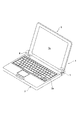
図1は本発明を実施したノート型パソコンを示す。図面によれば、このノート型パソコン1は、その上面にキーボード部2aを設けた第1の筐体2と、下面にディスプレイ部3aを設けた第2の筐体3と、この第2の筐体3と第1の筐体2を相対的に開閉する開閉装置4、5とで構成されている。
FIG. 1 shows a notebook personal computer embodying the present invention. According to the drawing, the notebook computer 1 includes a
開閉装置4と5は両方共同じ構造であっても良いが、以下の説明では本発明を左側の開閉装置4に実施した場合について説明する。勿論、このことは本発明を右側の開閉装置5に実施することを妨げるものではない。
Both the opening /
図2乃至図6は、本発明に係る開閉装置4を示す。図面によれば本発明に係る開閉装置4は、チルトヒンジ6とこのチルトヒンジ6の回動部の一例としてのヒンジシャフト9に作用する安定停止手段7とを組み合わせたものであり、まず、チルトヒンジ6の部分から説明する。
2 to 6 show the
チルトヒンジ6は、第1の筐体2の後端側部の上面に取り付けられるところの第1取付プレート部8aと、この第1取付プレート部8aの両端部より立ち上げた両側板8b、8bと、第1取付プレート部8aの手前側より立ち上げた取付板8cと、後端部側より立ち上げた壁板8dとから成る第1取付部材8と、この第1取付部材8の両側板8b、8bの軸受部8e、8eに設けた軸受孔8f、8fに回動可能に軸架されたフランジ部9aを有するヒンジシャフト9と、このヒンジシャフト9のフランジ部9aを設けた側にその軸受部10aに設けた軸受孔10bを挿通させた第2取付部材10と、この第2取付部材10の側に設けたフリクション機構11と、ヒンジシャフト9の他端部側に取り付けた支持部材12とで構成されている。尚、この支持部材12と第1取付部材8の側板8bとの間に、その中心部軸方向に設けた変形挿通孔26aをヒンジシャフト9の第4変形軸部9fに挿通させてスペーサー26が介在させてある。
The
さらに詳しく説明すると、ヒンジシャフト9は、フランジ部9aを挟んで第2取付部材10側にその端部より設けた断面が略楕円形状となる第1変形軸部9bと、この第1変形軸部9bに続いて設けられた若干厚みのある第2変形軸部9cとを有し、フランジ部9aを挟んだ支持部材12側に円形軸部9dとこの円形軸部9dに続いて設けられた同じく断面楕円形状の第3変形軸部9eと、この第3変形軸部9eに続いて設けた第4変形軸部9fと、フランジ部9aの縁部を切り欠いて設けた第1係止部9g及び第2係止部9hとを有している。
More specifically, the
第2取付部材10は、さらに、第1取付部材8の第1取付プレート部8aより延設した保持プレート部8hへ取付ビス27を介して取り付けられる第2取付プレート部10dと、この第2取付プレート部10dの側部より立ち上げた軸受部10aを有する側板10eとを有している。
The
フリクション機構11は、フランジ部9aの一側部と第1取付部材8の側板8bとの間にヒンジシャフト9の円形軸部9dをその中心部軸方向に設けた円形挿通孔13aへ挿通させると共に、その縁部に設けた第1係止片13bをフランジ部9aに設けた第1係止部9gと係合させている第1フリクションプレート13と、フランジ部9aと第2取付部材10との間にその中心部軸方向に設けた円形挿通孔14aへヒンジシャフト9の第2変形軸部9cを挿通させると共に、その縁部に設けた第2係止片14bをフランジ部9aに設けた第2係止部9hへ係止させた第2フリクションプレート14と、第2取付部材10の軸受部10aに設けたカム部10cと接する側にカム部15bを有し、互いのカム部10c、15bを当接した状態でその中心部軸方向に設けた変形挿通孔15aへヒンジシャフト9の第2変形軸部9cを挿通させて当該ヒンジシャフト9と共に回転するように成したカム部材15と、第2フリクションプレート14に当接してその中心部軸方向に設けた挿通孔16aへヒンジシャフト9の第1変形軸部9bと第2変形軸部9cにかけて挿通させて設けた複数の皿バネ16(或はスプリングワッシャー)と、この皿バネ16に当接して、その変形取付孔17aをヒンジシャフト9の端部に嵌めてかしめて固定された固定ワッシャー17とから成り、この固定ワッシャー17をヒンジシャフト9の端部へ当該ヒンジシャフト9の端部をかしめて固定する圧力により、皿バネ16を介してカム部材15のカム部15bが第2取付部材10の軸受部10aに設けたカム部10cに圧接し、第2フリクションプレート14がフランジ部9aと第2取付部材10の軸受部10aとの間に圧接される構成である。尚、第1フリクションプレート13はフランジ部9aの他側面と第1取付部材8の側板8bとの間に圧接される。
The
次に、安定停止手段7について説明する。この安定停止手段7は、当該ヒンジシャフト9の第4変形軸部9fをその中心部軸方向に設けた変形挿通孔18aへ挿通させてヒンジシャフト9に回転を拘束されて取り付けられたテーパー部材18と、このテーパー部材18のテーパー外周部18bにそのテーパー湾曲部19aを当接させて第1取付部材8の第1取付プレート部8a上にヒンジシャフト9の軸方向へスライド可能に設置された押圧部材19と、第1取付部材8の取付板8cに設けた取付孔8gへEリング20を介して取り付けた支持ピン21にその軸着孔22aを取り付けてヒンジシャフト9の軸方向左右へ揺動可能に取り付けられる共に、それ自身に設けた係合凹部22bを押圧部材19の係合凸部19bと係合させて成る樹脂材質(又は熱可塑性樹脂)の揺動部材22と、で構成されている。尚、テーパー部材18と側板8bとの間にその中心部軸方向に設けた挿通孔25aへヒンジシャフト9の円形軸部9dを挿通させて介在させたものはスペーサー25である。
Next, the stable stop means 7 will be described. The stable stopping means 7 is a
そして、図3と図4において、揺動部材22の上部に並列させて指示記号23、24で示したものは、操作ボタンであり、指示記号23のものが操作ONボタン、指示記号24のものは操作OFFボタンである。この操作ONボタン23と操作OFFボタン24は、揺動部材22の隆起部22dと22eの上に位置して第1の筐体2の上面に露出して突出しているので、これを押圧操作することができる構成である。
In FIGS. 3 and 4, the
次に、上述した本発明に係る開閉装置4の作用効果について説明する。尚、以下の説明では図面において充分に図示されていないが、開閉装置4の第1取付部材8と第2取付部材10には、第1の筐体2の後部が取り付けられ、開閉装置4の支持部材12には第2の筐体3の後部が取り付けられているものとして説明する。
Next, the effect of the
まず、通常の状態において、第1の筐体2と第2の筐体3を開閉装置4を介して相対的に開閉させると、開閉装置4のチルトヒンジ6の部分が動作して第2の筐体3は第1の筐体2に対して、フリクション機構11のフリクション機能により任意の開閉位置でフリーストップに開閉することができ、任意の開閉角度で手を離しても第2の筐体3が第1の筐体2に対して自然落下してしまう心配はない。操作者は第2の筐体3を第1の筐体2に対してディスプレイ部3aを見易い任意の開成角度に開いた状態で、第1の筐体2のキーボード部2aを操作してノート型パソコン1を使用することができる。
First, when the
通常の使用はこのチルトヒンジ6の持つフリクション機能により支障が生じない。しかしながら、第2の筐体3のディスプレイ部3aのディスプレイ画面を手指でタッチして操作する場合には、このタッチ操作によって、第2の筐体3が後方へ押されるので、タッチ操作を繰り返すと、フリクション機構11の停止保持能力を超えてしまい、第2の筐体3が押されて後方へ回転してしまうので、本発明に係る安定停止手段7を用いることが必要となる。
In normal use, no trouble occurs due to the friction function of the
第2の筐体3が第1の筐体2に対して丁度良い使用角度になった時に、操作ONボタン23を下押しすると、揺動部材22が支持ピン21を支点に時計方向へ揺動するので押圧部材19が左方向へスライドしてテーパー湾曲部19aでテーパー部材18のテーパー外周部18bと圧接することにより、ヒンジシャフト9の回転は阻止されるので、ヒンジシャフト9の第4変形軸部9fの端部にその変形取付孔12aをかしめて固定した支持部材12を介して第2の筐体3は、ディスプレイ画面を手指でタッチされても後方へ回転してしまうのを阻止されるものである。このようにして、ノート型パソコン1の操作性が向上する。
If the operation ON
ノート型パソコン1の使用が終わったら、操作OFFボタン24を下押しすると、揺動部材22が支持ピン21を支点に反時計方向へ揺動し、同時に押圧部材19を右方向へスライドさせるので、押圧部材19のテーパー湾曲部19aによるテーパー部材18に対する圧接力が解けてヒンジシャフト9にはフリクション機構11のフリクショントルクのみが作用することにより、フリーストップで開閉操作を行なうことが可能となるものである。
When the use of the notebook computer 1 is finished, when the operation OFF
さらに、第2の筐体3を第1の筐体2に対して閉じる際には、ヒンジシャフト9と共に回転するカム部材15のカム部15bと第2取付部材10の軸受部10aに設けたカム部10cによる公知の吸い込み機能により、第2の筐体3は第1の筐体2に対し閉成状態でロックされることになる。
Further, when the
このカム部材15のカム部15bと第2取付部材10のカム部10cによるロック機能は他の任意の開閉角度で用いることが可能である。
The lock function by the
次に、図示はしてないが、その他の実施例として、チルトヒンジの構成は、ヒンジシャフトの回動を取付部材に規制させて非回転とし、この非回転のヒンジシャフトへ回動部としての支持部材を回転可能に軸支させ、この支持部材とヒンジシャフトとの間にフリクション機構を設けるように構成しても良い。 Next, although not shown in the drawings, as another embodiment, the tilt hinge is configured so that the rotation of the hinge shaft is restricted by the mounting member so that it does not rotate, and the non-rotating hinge shaft is supported as a rotating portion. The member may be rotatably supported, and a friction mechanism may be provided between the support member and the hinge shaft.
さらに、フリクション機構は、実施例では取付部材を第1取付部材8と第2取付部材10とで構成し、主として第2取付部材10の側にフリクション機構11を設けた場合について説明したが、このものに限定されず、取付部材を構成する第2取付部材10を省略して第1取付部材8のみとし、この第1取付部材8の側にフリクション機構を設けても良い。また、安定停止手段は、ブラケットの回転を停止させる構成のものであっても良い。さらに、カム部材はこれがなくとも安定停止手段としては機能する。さらに、押圧部材は弾性手段を用いて安定停止状態を維持するように構成することもできる。要するにチルトヒンジに作用してその回動部の動きを停止させるものであれば足りる。
Furthermore, the friction mechanism has been described in the embodiment in which the mounting member is composed of the first mounting
本発明は以上のように構成したので、キーボード部を有する第1の筐体に対しディスプレイ部を設けた第2の筐体を有する小型電子機器において、第2の筐体に設けた押ボタンやディスプレイ画面を手指でタッチ操作するものに広く利用することが可能である。 Since the present invention is configured as described above, in a small electronic device having a second casing provided with a display unit with respect to the first casing having a keyboard unit, a push button provided in the second casing, The display screen can be widely used for touch operations with fingers.
1 ノート型パソコン
2 第1の筐体
3 第2の筐体
4 開閉装置
5 開閉装置
6 チルトヒンジ
7 安定停止手段
8 第1取付部材
8e 軸受部
9 ヒンジシャフト
10 第2取付部材
10a 軸受部
11 フリクション機構
12 支持部材
18 テーパー部材
19 押圧部材
22 揺動部材
DESCRIPTION OF SYMBOLS 1 Notebook-type
DESCRIPTION OF
Claims (6)
前記チルトヒンジのヒンジシャフトの軸方向へスライドして当該ヒンジシャフトに圧接可能に設けられた押圧部材と、この押圧部材と係合し当該押圧部材を前記ヒンジシャフトの軸方向へスライドさせて当該ヒンジシャフトへ圧接させる揺動部材とで構成したことを特徴とする、小型電子機器の開閉装置。 The tilt hinge includes a tilt hinge that relatively opens and closes the first housing and the second housing of the small electronic device, and stable stop means that stably stops the movement of the tilt hinge.
A pressing member that is slidable in the axial direction of the hinge shaft of the tilt hinge and press-contacted to the hinge shaft, and engages with the pressing member and slides the pressing member in the axial direction of the hinge shaft. An opening / closing device for a small electronic device , characterized by comprising a swinging member that is pressed against the surface.
Priority Applications (3)
| Application Number | Priority Date | Filing Date | Title |
|---|---|---|---|
| JP2010032138A JP5489769B2 (en) | 2010-02-17 | 2010-02-17 | Opening / closing device for small electronic device and small electronic device using the opening / closing device |
| CN201110039880.XA CN102170762B (en) | 2010-02-17 | 2011-02-17 | Opening and closing means of small-sized electronic device and small-sized electronic device applying the same |
| TW100105230A TWI460355B (en) | 2010-02-17 | 2011-02-17 | Opening-closing device of small electronic apparatus and small electronic apparatus using the same |
Applications Claiming Priority (1)
| Application Number | Priority Date | Filing Date | Title |
|---|---|---|---|
| JP2010032138A JP5489769B2 (en) | 2010-02-17 | 2010-02-17 | Opening / closing device for small electronic device and small electronic device using the opening / closing device |
Publications (3)
| Publication Number | Publication Date |
|---|---|
| JP2011169361A JP2011169361A (en) | 2011-09-01 |
| JP2011169361A5 JP2011169361A5 (en) | 2013-04-04 |
| JP5489769B2 true JP5489769B2 (en) | 2014-05-14 |
Family
ID=44491689
Family Applications (1)
| Application Number | Title | Priority Date | Filing Date |
|---|---|---|---|
| JP2010032138A Expired - Fee Related JP5489769B2 (en) | 2010-02-17 | 2010-02-17 | Opening / closing device for small electronic device and small electronic device using the opening / closing device |
Country Status (3)
| Country | Link |
|---|---|
| JP (1) | JP5489769B2 (en) |
| CN (1) | CN102170762B (en) |
| TW (1) | TWI460355B (en) |
Families Citing this family (4)
| Publication number | Priority date | Publication date | Assignee | Title |
|---|---|---|---|---|
| TWI475358B (en) * | 2012-05-08 | 2015-03-01 | Acer Inc | Electronic device and hinge unit thereof |
| CN103838301B (en) * | 2012-11-23 | 2017-04-26 | 纬创资通股份有限公司 | Electromagnetic fixing mechanism and electronic device for limiting touch control display module pivoting |
| WO2015037040A1 (en) * | 2013-09-13 | 2015-03-19 | 富士通株式会社 | Electronic device and information processing apparatus |
| JP6090460B2 (en) | 2013-09-13 | 2017-03-08 | 富士通株式会社 | Electronic apparatus and information processing apparatus |
Family Cites Families (12)
| Publication number | Priority date | Publication date | Assignee | Title |
|---|---|---|---|---|
| JPS567998Y2 (en) * | 1976-07-24 | 1981-02-21 | ||
| JP2564862Y2 (en) * | 1991-07-02 | 1998-03-11 | 株式会社加藤スプリング製作所 | Shaft locking device |
| JP2770297B2 (en) * | 1993-10-18 | 1998-06-25 | 宏一 渡部 | Movable body opening / closing suppression device |
| JPH0893747A (en) * | 1994-08-08 | 1996-04-09 | Hitachi Electron Service Co Ltd | Shaft lock device |
| JPH09158942A (en) * | 1995-12-06 | 1997-06-17 | Toran Support:Kk | Lock mechanism for weight lifter |
| JP2003060758A (en) * | 2001-08-16 | 2003-02-28 | Kyocera Corp | Portable terminal device |
| JP2007281345A (en) * | 2006-04-11 | 2007-10-25 | Sony Corp | Stand rotation mechanism, and electronic apparatus |
| JP2008196655A (en) * | 2007-02-15 | 2008-08-28 | Shimonishi Giken Kogyo Kk | Tilt hinge |
| JP2007211985A (en) * | 2007-04-11 | 2007-08-23 | Futaba Kinzoku Kogyo Kk | Torsion spring type hinge |
| CN201041192Y (en) * | 2007-05-21 | 2008-03-26 | 安捷资讯科技(苏州)有限公司 | Pivotal device |
| CN201125936Y (en) * | 2007-12-20 | 2008-10-01 | 中国电子科技集团公司第二十八研究所 | Heavy type screen turning and combining damping mechanism |
| JP5112093B2 (en) * | 2008-02-01 | 2013-01-09 | 加藤電機株式会社 | Small hinge and small electronic device using this small hinge |
-
2010
- 2010-02-17 JP JP2010032138A patent/JP5489769B2/en not_active Expired - Fee Related
-
2011
- 2011-02-17 TW TW100105230A patent/TWI460355B/en active
- 2011-02-17 CN CN201110039880.XA patent/CN102170762B/en not_active Expired - Fee Related
Also Published As
| Publication number | Publication date |
|---|---|
| CN102170762A (en) | 2011-08-31 |
| TWI460355B (en) | 2014-11-11 |
| JP2011169361A (en) | 2011-09-01 |
| TW201129754A (en) | 2011-09-01 |
| CN102170762B (en) | 2014-10-15 |
Similar Documents
| Publication | Publication Date | Title |
|---|---|---|
| CN104938041B (en) | Hinge component | |
| JP5014245B2 (en) | Support device with tilt mechanism | |
| JP5489769B2 (en) | Opening / closing device for small electronic device and small electronic device using the opening / closing device | |
| KR20050056147A (en) | Electronic device with improved hinge | |
| JP5805419B2 (en) | Hinge device, opening / closing device, and portable device | |
| JP6291006B1 (en) | Switch device and electronic device | |
| US20130127318A1 (en) | Clamshell device | |
| US20140021727A1 (en) | Opening-aid locking/unlocking mechanism of electronic device | |
| JP2014067397A (en) | Electronic apparatus | |
| US20110102982A1 (en) | Electronic apparatus | |
| WO2009123604A1 (en) | Computing device locking mechanisms | |
| KR200472450Y1 (en) | Hinge assembly | |
| US8085532B2 (en) | Electronic device | |
| JP2011096118A (en) | Electronic equipment | |
| EP3161578B1 (en) | Computing device with a rotatable display member | |
| TWM491101U (en) | Hinge composed of plural moveable joints | |
| TWM460503U (en) | Hinge assembly and slide electronic apparatus | |
| TW201032024A (en) | Cover structure | |
| JP4016503B2 (en) | Electronic device having an open / close lid | |
| JP5889522B2 (en) | Electronic device switching device and electronic device | |
| TWI428085B (en) | Opening-closing device and small electronic device using the same | |
| JP2004326440A (en) | Information processor | |
| JP2012073919A (en) | Information processing apparatus | |
| JP4566018B2 (en) | Rotating device | |
| WO2019193794A1 (en) | Washing machine |
Legal Events
| Date | Code | Title | Description |
|---|---|---|---|
| A521 | Written amendment |
Free format text: JAPANESE INTERMEDIATE CODE: A523 Effective date: 20130215 |
|
| A621 | Written request for application examination |
Free format text: JAPANESE INTERMEDIATE CODE: A621 Effective date: 20130215 |
|
| A977 | Report on retrieval |
Free format text: JAPANESE INTERMEDIATE CODE: A971007 Effective date: 20130917 |
|
| A131 | Notification of reasons for refusal |
Free format text: JAPANESE INTERMEDIATE CODE: A131 Effective date: 20130924 |
|
| A977 | Report on retrieval |
Free format text: JAPANESE INTERMEDIATE CODE: A971007 Effective date: 20131111 |
|
| A521 | Written amendment |
Free format text: JAPANESE INTERMEDIATE CODE: A523 Effective date: 20131121 |
|
| TRDD | Decision of grant or rejection written | ||
| A01 | Written decision to grant a patent or to grant a registration (utility model) |
Free format text: JAPANESE INTERMEDIATE CODE: A01 Effective date: 20140204 |
|
| A61 | First payment of annual fees (during grant procedure) |
Free format text: JAPANESE INTERMEDIATE CODE: A61 Effective date: 20140225 |
|
| R150 | Certificate of patent or registration of utility model |
Ref document number: 5489769 Country of ref document: JP Free format text: JAPANESE INTERMEDIATE CODE: R150 |
|
| LAPS | Cancellation because of no payment of annual fees |