JP2011169361A5 - - Google Patents

Download PDF

Info

Publication number
JP2011169361A5
JP2011169361A5 JP2010032138A JP2010032138A JP2011169361A5 JP 2011169361 A5 JP2011169361 A5 JP 2011169361A5 JP 2010032138 A JP2010032138 A JP 2010032138A JP 2010032138 A JP2010032138 A JP 2010032138A JP 2011169361 A5 JP2011169361 A5 JP 2011169361A5
Authority
JP
Japan
Prior art keywords
hinge shaft
shaft
mounting
deformation
mounting member
Prior art date
Legal status (The legal status is an assumption and is not a legal conclusion. Google has not performed a legal analysis and makes no representation as to the accuracy of the status listed.)
Granted
Application number
JP2010032138A
Other languages
Japanese (ja)
Other versions
JP2011169361A (en
JP5489769B2 (en
Filing date
Publication date
Application filed filed Critical
Priority to JP2010032138A priority Critical patent/JP5489769B2/en
Priority claimed from JP2010032138A external-priority patent/JP5489769B2/en
Priority to CN201110039880.XA priority patent/CN102170762B/en
Priority to TW100105230A priority patent/TWI460355B/en
Publication of JP2011169361A publication Critical patent/JP2011169361A/en
Publication of JP2011169361A5 publication Critical patent/JP2011169361A5/ja
Application granted granted Critical
Publication of JP5489769B2 publication Critical patent/JP5489769B2/en
Expired - Fee Related legal-status Critical Current
Anticipated expiration legal-status Critical

Links

Images

Description

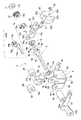
フリクション機構11は、フランジ部9aの一側部と第1取付部材8の側板8bとの間にヒンジシャフト9の円形軸部9dをその中心部軸方向に設けた円形挿通孔13aへ挿通させると共に、その縁部に設けた第1係止片13bをフランジ部9aに設けた第1係止部9gと係合させている第1フリクションプレート13と、フランジ部9aと第2取付部材10との間にその中心部軸方向に設けた円形挿通孔14aへヒンジシャフト9の第2変形軸部9cを挿通させると共に、その縁部に設けた第2係止片14bをフランジ部9aに設けた第2係止部9hへ係止させた第2フリクションプレート14と、第2取付部材10の軸受部10aに設けたカム部10cと接する側にカム部15bを有し、互いのカム部10c、15bを当接した状態でその中心部軸方向に設けた変形挿通孔15aへヒンジシャフト9の第2変形軸部9cを挿通させて当該ヒンジシャフト9と共に回転するように成したカム部材15と、第2フリクションプレート14に当接してその中心部軸方向に設けた挿通孔16aへヒンジシャフト9の第1変形軸部9bと第2変形軸部9cにかけて挿通させて設けた複数の皿バネ16(或はスプリングワッシャー)と、この皿バネ16に当接して、その変形取付孔17aをヒンジシャフト9の端部に嵌めてかしめて固定された固定ワッシャー17とから成り、この固定ワッシャー17をヒンジシャフト9の端部へ当該ヒンジシャフト9の端部をかしめて固定する圧力により、皿バネ16を介してカム部材15のカム部15bが第2取付部材10の軸受部10aに設けたカム部10cに圧接し、第2フリクションプレート14がフランジ部9aと第2取付部材10の軸受部10aとの間に圧接される構成である。尚、第1フリクションプレート13はフランジ部9aの他側面と第1取付部材8の側板8bとの間に圧接される。 The friction mechanism 11 inserts the circular shaft portion 9d of the hinge shaft 9 between the one side portion of the flange portion 9a and the side plate 8b of the first mounting member 8 into a circular insertion hole 13a provided in the central portion axial direction. The first friction plate 13 engaging the first locking piece 13b provided on the edge with the first locking portion 9g provided on the flange portion 9a, and the flange portion 9a and the second mounting member 10 A second deforming shaft portion 9c of the hinge shaft 9 is inserted into a circular insertion hole 14a provided in the center axial direction therebetween, and a second locking piece 14b provided on the edge thereof is provided in the flange portion 9a. The second friction plate 14 locked to the two locking portions 9h and the cam portion 15b on the side contacting the cam portion 10c provided on the bearing portion 10a of the second mounting member 10 have a cam portion 10c, 15b. In contact with The second deformation shaft portion 9c of the hinge shaft 9 is inserted into the deformation insertion hole 15a provided in the central axis direction so as to rotate with the hinge shaft 9 and the second friction plate 14 abuts. A plurality of disc springs 16 (or spring washers) provided to be inserted through the first deformation shaft portion 9b and the second deformation shaft portion 9c of the hinge shaft 9 into an insertion hole 16a provided in the center axis direction of the lever, It comprises a fixed washer 17 that abuts against the disc spring 16 and is fixed by crimping its deformation mounting hole 17a to the end of the hinge shaft 9, and this fixed washer 17 is connected to the end of the hinge shaft 9 by the hinge shaft 9 the pressure for securing an end of 9 by caulking, cam the cam portion 15b of the cam member 15 via the disc spring 16 is provided in the bearing portion 10a of the second mounting member 10 Pressed against the 10c, a structure in which the second friction plate 14 is pressed against between the bearing portion 10a of the flange portion 9a and the second mounting member 10. The first friction plate 13 is pressed between the other side surface of the flange portion 9 a and the side plate 8 b of the first mounting member 8.

次に、安定停止手段7について説明する。この安定停止手段7は、当該ヒンジシャフト9の第4変形軸部9fをその中心部軸方向に設けた変形挿通孔18aへ挿通させてヒンジシャフト9に回転を拘束されて取り付けられたテーパー部材18と、このテーパー部材18のテーパー外周部18bにそのテーパー湾曲部19aを当接させて第1取付部材8の第1取付プレート部8a上にヒンジシャフト9の軸方向へスライド可能に設置された押圧部材19と、第1取付部材8の取付板8cに設けた取付孔8gへEリング20を介して取り付けた支持ピン21その軸着孔22aを取り付けてヒンジシャフト9の軸方向左右へ揺動可能に取り付けられる共に、それ自身に設けた係合凹部22bを押圧部材19の係合凸部19bと係合させて成る樹脂材質(又は熱可塑性樹脂)の揺動部材22と、で構成されている。尚、テーパー部材18と側板8bとの間にその中心部軸方向に設けた挿通孔25aへヒンジシャフト9の円形軸部9dを挿通させて介在させたものはスペーサー25である。 Next, the stable stop means 7 will be described. The stable stopping means 7 is a taper member 18 attached to the hinge shaft 9 by restricting the rotation by inserting the fourth deformation shaft portion 9f of the hinge shaft 9 into a deformation insertion hole 18a provided in the axial direction of the central portion. And a taper outer peripheral portion 18b of the taper member 18 with its taper curved portion 19a abutting on the first mounting plate portion 8a of the first mounting member 8 so as to be slidable in the axial direction of the hinge shaft 9 a member 19, swinging mounting the shaft attachment hole 22a to the support pin 21 mounted through the E-ring 20 into the mounting hole 8g formed in the mounting plate 8c of the first mounting member 8 in the axial direction left and right hinge shaft 9 The oscillating member 22 made of a resin material (or thermoplastic resin), which is attached so as to be able to engage with the engaging convex portion 19b of the pressing member 19 with the engaging concave portion 22b provided on itself. , In is configured. A spacer 25 is formed by inserting the circular shaft portion 9d of the hinge shaft 9 through the insertion hole 25a provided in the axial direction of the central portion between the taper member 18 and the side plate 8b.

JP2010032138A 2010-02-17 2010-02-17 Opening / closing device for small electronic device and small electronic device using the opening / closing device Expired - Fee Related JP5489769B2 (en)

Priority Applications (3)

Application Number Priority Date Filing Date Title
JP2010032138A JP5489769B2 (en) 2010-02-17 2010-02-17 Opening / closing device for small electronic device and small electronic device using the opening / closing device
CN201110039880.XA CN102170762B (en) 2010-02-17 2011-02-17 Opening and closing means of small-sized electronic device and small-sized electronic device applying the same
TW100105230A TWI460355B (en) 2010-02-17 2011-02-17 Opening-closing device of small electronic apparatus and small electronic apparatus using the same

Applications Claiming Priority (1)

Application Number Priority Date Filing Date Title
JP2010032138A JP5489769B2 (en) 2010-02-17 2010-02-17 Opening / closing device for small electronic device and small electronic device using the opening / closing device

Publications (3)

Publication Number Publication Date
JP2011169361A JP2011169361A (en) 2011-09-01
JP2011169361A5 true JP2011169361A5 (en) 2013-04-04
JP5489769B2 JP5489769B2 (en) 2014-05-14

Family

ID=44491689

Family Applications (1)

Application Number Title Priority Date Filing Date
JP2010032138A Expired - Fee Related JP5489769B2 (en) 2010-02-17 2010-02-17 Opening / closing device for small electronic device and small electronic device using the opening / closing device

Country Status (3)

Country Link
JP (1) JP5489769B2 (en)
CN (1) CN102170762B (en)
TW (1) TWI460355B (en)

Families Citing this family (4)

* Cited by examiner, † Cited by third party
Publication number Priority date Publication date Assignee Title
TWI475358B (en) * 2012-05-08 2015-03-01 Acer Inc Electronic device and hinge unit thereof
CN103838301B (en) * 2012-11-23 2017-04-26 纬创资通股份有限公司 Electromagnetic fixing mechanism and electronic device for limiting touch control display module pivoting
JP6090460B2 (en) 2013-09-13 2017-03-08 富士通株式会社 Electronic apparatus and information processing apparatus
WO2015037040A1 (en) * 2013-09-13 2015-03-19 富士通株式会社 Electronic device and information processing apparatus

Family Cites Families (12)

* Cited by examiner, † Cited by third party
Publication number Priority date Publication date Assignee Title
JPS567998Y2 (en) * 1976-07-24 1981-02-21
JP2564862Y2 (en) * 1991-07-02 1998-03-11 株式会社加藤スプリング製作所 Shaft locking device
JP2770297B2 (en) * 1993-10-18 1998-06-25 宏一 渡部 Movable body opening / closing suppression device
JPH0893747A (en) * 1994-08-08 1996-04-09 Hitachi Electron Service Co Ltd Shaft lock device
JPH09158942A (en) * 1995-12-06 1997-06-17 Toran Support:Kk Lock mechanism for weight lifter
JP2003060758A (en) * 2001-08-16 2003-02-28 Kyocera Corp Portable terminal device
JP2007281345A (en) * 2006-04-11 2007-10-25 Sony Corp Stand rotation mechanism, and electronic apparatus
JP2008196655A (en) * 2007-02-15 2008-08-28 Shimonishi Giken Kogyo Kk Tilt hinge
JP2007211985A (en) * 2007-04-11 2007-08-23 Futaba Kinzoku Kogyo Kk Torsion spring type hinge
CN201041192Y (en) * 2007-05-21 2008-03-26 安捷资讯科技(苏州)有限公司 Pivotal device
CN201125936Y (en) * 2007-12-20 2008-10-01 中国电子科技集团公司第二十八研究所 Heavy type screen turning and combining damping mechanism
JP5112093B2 (en) * 2008-02-01 2013-01-09 加藤電機株式会社 Small hinge and small electronic device using this small hinge

Similar Documents

Publication Publication Date Title
JP2011169361A5 (en)
JP2007313292A5 (en)
EP2789871B1 (en) Bicycle disc brake apparatus
JP2007054715A5 (en)
WO2010022956A8 (en) Pedal arrangement with a standing pedal pivoting about a horizontal axis
JP2012042003A5 (en)
FR2963767A1 (en) MOTOR VEHICLE BRAKE MECHANICAL ACTUATOR CARTRIDGE
KR101405994B1 (en) Pumping device for vehicle seat
JP2014058993A5 (en)
JP5598976B2 (en) Side stand switch and side stand device
US8789864B2 (en) Spring box for door handle
JP2011052730A5 (en)
JP6407586B2 (en) Hinge
JP4223221B2 (en) Hinge mechanism
WO2021017324A1 (en) Brake apparatus and lawn mower
JP2012112420A (en) Torque fluctuation absorbing device
JP2011012751A5 (en)
GB2422646A (en) A device for fixing recreational equipment to a support spring
JP5913497B2 (en) Centrifugal clutch device
CN106062425B (en) Power transmission
FR3009593A1 (en) VIBRATION DAMPING DEVICE
JP2012167727A (en) Power transmission device
JP5467200B2 (en) Side stand switch and side stand device
JP2008133945A (en) Hinge mechanism
CH710250A2 (en) Device detachable coaxial wheels of a watch movement.