JP5488008B2 - Contamination separator - Google Patents
Contamination separator Download PDFInfo
- Publication number
- JP5488008B2 JP5488008B2 JP2010020088A JP2010020088A JP5488008B2 JP 5488008 B2 JP5488008 B2 JP 5488008B2 JP 2010020088 A JP2010020088 A JP 2010020088A JP 2010020088 A JP2010020088 A JP 2010020088A JP 5488008 B2 JP5488008 B2 JP 5488008B2
- Authority
- JP
- Japan
- Prior art keywords
- particles
- aggregated
- foreign matter
- lithium manganate
- ultrasonic
- Prior art date
- Legal status (The legal status is an assumption and is not a legal conclusion. Google has not performed a legal analysis and makes no representation as to the accuracy of the status listed.)
- Expired - Fee Related
Links
Images


Classifications
-
- Y—GENERAL TAGGING OF NEW TECHNOLOGICAL DEVELOPMENTS; GENERAL TAGGING OF CROSS-SECTIONAL TECHNOLOGIES SPANNING OVER SEVERAL SECTIONS OF THE IPC; TECHNICAL SUBJECTS COVERED BY FORMER USPC CROSS-REFERENCE ART COLLECTIONS [XRACs] AND DIGESTS
- Y02—TECHNOLOGIES OR APPLICATIONS FOR MITIGATION OR ADAPTATION AGAINST CLIMATE CHANGE
- Y02E—REDUCTION OF GREENHOUSE GAS [GHG] EMISSIONS, RELATED TO ENERGY GENERATION, TRANSMISSION OR DISTRIBUTION
- Y02E60/00—Enabling technologies; Technologies with a potential or indirect contribution to GHG emissions mitigation
- Y02E60/10—Energy storage using batteries
Description
この発明はコンタミネーション分離装置に関する。 This invention relates to the co emissions Tamil Nation separation equipment.
リチウムイオンバッテリ等の非水系二次電池の活物質にコンタミネーション(汚染物質)としての金属等の異物(以下「金属異物」という。)が混入すると、金属異物は、セル内で溶出・析出し電池が内部短絡を生じる可能性がある。自動車用電池は、ライフサイクルが長いこと、また内部短絡が生じたときの短絡電流の大きさことから、コンタミネーション対策を行うものがある(特許文献1参照)。 When foreign materials such as metals (hereinafter referred to as “metal foreign materials”) as contamination (contaminants) enter the active material of non-aqueous secondary batteries such as lithium ion batteries, the metal foreign materials are eluted and deposited in the cell. The battery can cause an internal short circuit. Some automobile batteries take a countermeasure against contamination due to the long life cycle and the magnitude of the short-circuit current when an internal short circuit occurs (see Patent Document 1).
ところで、上記特許文献1の技術では、活物質に混入した金属異物を磁力により(磁石棒を挿入した磁選部を設ける)捕捉している。しかしながら、金属異物が活物質と凝集粒子を形成している場合、凝集粒子ごとコンタミネーションとして回収することになり、活物質の利用率が悪くなる。
By the way, in the technique of the said
そこで本発明は、活物質の利用率を高め得る装置及び方法を提供することを目的とする。 Then, an object of this invention is to provide the apparatus and method which can raise the utilization factor of an active material.
本発明は、ケースの一端に材料投入口、ケースの他端に排出口を有し、材料投入口から排出口に向けて、活物質の一次粒子及び不純物粒子を含んだケース内の凝集粒子を搬送する搬送手段と、超音波発生手段と、不純物分離部とを備えている。そして、上記の超音波発生手段は前記搬送手段により搬送される凝集粒子に前記活物質材料の粒径分布に合わせた超音波を段階的に作用させて凝集粒子を単粒子へと分解する。上記の不純物分離部は前記排出口より排出される、単粒子へと分解された活物質の一次粒子及び単粒子へと分解された不純物粒子を導入し、不純物粒子のみをコンタミネーションして分離する。 The present invention has a material inlet at one end of the case and an outlet at the other end of the case, and the aggregated particles in the case containing primary particles and impurity particles of the active material are directed from the material inlet to the outlet. A conveying means for conveying, an ultrasonic wave generating means, and an impurity separation unit are provided. Then, the ultrasonic wave generating means decomposes the aggregated particles into single particles by applying an ultrasonic wave stepwise to the aggregated particles conveyed by the conveying means in accordance with the particle size distribution of the active material. The impurity separation unit introduces primary particles of the active material decomposed into single particles and impurity particles decomposed into single particles discharged from the discharge port, and contaminates and separates only the impurity particles. .
本発明によれば、金属異物が含まれる凝集粒子に対して活物質材料の粒径分布に合わせた周波数の超音波を段階的に作用させるので、ある程度の粒径分布を有する活物質材料の粒子に金属異物が混入して凝集粒子を形成している場合であっても、単粒子への分解を確実に行わせることができる。 According to the present invention, since the ultrasonic wave having a frequency matched to the particle size distribution of the active material is made to act on the agglomerated particles containing the foreign metal particles in a stepwise manner, the particles of the active material having a certain particle size distribution Even when a metal foreign matter is mixed in to form aggregated particles, decomposition into single particles can be performed reliably.
以下、本発明の実施形態を、図面を参照しながら説明する。 Embodiments of the present invention will be described below with reference to the drawings.
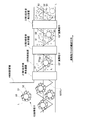
図1は比較例のコンタミネーション分離装置1の概略構成図である。コンタミネーション分離装置1には凝集粒子分解装置が含まれている。
FIG. 1 is a schematic configuration diagram of a
図1においてコンタミネーション分離装置1にはスクリューフィーダー2(搬送手段)を備える。スクリューフィーダー2は、ケース3の一端に材料投入口、ケース3の他端に排出口を有し、スクリューを回転することによって材料投入口から排出口に向けて、活物質(非水系二次電池の電極材料)の粒子及び不純物粒子を含んだケース3内の凝集粒子を搬送するものである。
In FIG. 1, the
具体的には、スクリューフィーダーのケース3は、材料貯留部4と、材料供給部5とからなる。材料貯留部4の上部に材料投入口4aが設けられ、この材料投入口4aより活物質であるマンガン酸リチウム(LiMn2O4)の粉末が図1矢印Aのように投入される。マンガン酸リチウムはミルにより5〜40μmまでの分布を有する粒径範囲の粒子(この粒子を「一次粒子」という。)に粉砕されている。なお、以下ではマンガン酸リチウムの一次粒子を単に一次粒子ということがある。
Specifically, the
一端が材料貯留部4の側壁下部に開口する材料供給部5はほぼ円筒状に形成され、材料供給部5の他端(図で右端)に排出口5aが設けられている。排出口5aは円筒状の分離機構部8の側壁8aに開口している。
The material supply
材料供給部5及び材料貯留部4の下部を貫いてスクリュー6が設けられている。このスクリュー6により、マンガン酸リチウムの一次粒子は、材料貯留部4より図1矢印Bのように排出口5aへと搬送される。排出口5aからは図1矢印Cのようにマンガン酸リチウムの一次粒子が分離機構部8の内部へと投下される。7はスクリュー6を駆動するモータである。
A
上記ケース3の材質は柔軟性を有する樹脂とし、樹脂で材料貯留部4と材料供給部5とを一体形成している。
The material of the
非水系二次電池の製造工程中での金属異物の混入が指摘されている。マンガン酸リチウムの粒径は5〜40μmであり、これら粒径範囲にある一次粒子では分子間力が働いて凝集しやすい特性を有している。この場合、凝集はマンガン酸リチウムの一次粒子とマンガン酸リチウムの一次粒子との間で生じるが、マンガン酸リチウムの一次粒子と上記金属異物との間でも凝集が容易に生じる。言い換えると、マンガン酸リチウムの一次粒子同士が凝集した凝集粒子やマンガン酸リチウムの一次粒子と金属異物とが凝集した凝集粒子とが材料貯留部4の内部で生じる。なお、凝集していない状態でのマンガン酸リチウムの一次粒子や凝集していない状態での金属異物を以下「単粒子」という。
It has been pointed out that metal foreign matters are mixed during the manufacturing process of the non-aqueous secondary battery. The particle size of lithium manganate is 5 to 40 μm, and the primary particles in these particle size ranges have a characteristic that they tend to aggregate due to the intermolecular force. In this case, aggregation occurs between primary particles of lithium manganate and primary particles of lithium manganate, but aggregation also easily occurs between primary particles of lithium manganate and the metal foreign matter. In other words, aggregated particles obtained by agglomerating primary particles of lithium manganate or aggregated particles obtained by agglomerating primary particles of lithium manganate and metal foreign matter are generated inside the
図1において材料貯留部4の内部に、マンガン酸リチウムの一次粒子S同士が凝集した凝集粒子G1と、マンガン酸リチウムの一次粒子Sと金属異物Lとが凝集した凝集粒子G2とをモデルで示している。ここでは簡単のため、マンガン酸リチウムの一次粒子Sの径は一様であるとし、マンガン酸リチウムの一次粒子Sを相対的に小さな粒子で、金属異物Lを相対的に大きな粒子で表している。なお、各粒子S、Lを球状で示しているが、各粒子S、Lの形状が球状である場合に限定されるものでない。
In FIG. 1, aggregated particles G1 in which primary particles S of lithium manganate are aggregated and aggregated particles G2 in which primary particles S of lithium manganate and metal foreign matter L are aggregated are shown as models in the
さて、特に金属異物Lが含まれる凝集粒子G2を用いて活物質が形成されてしまうと(つまり電池の活物質に金属異物が混入すると)、金属異物Lは、セル内で溶出・析出し電池が内部短絡を生じる可能性がある。自動車用電池は、ライフサイクルが長いこと、内部短絡が生じたときの短絡電流の大きさことから、金属異物Lを取り去る必要がある。 Now, especially when the active material is formed using the aggregated particles G2 containing the metal foreign matter L (that is, when the metal foreign matter is mixed in the active material of the battery), the metal foreign matter L is eluted and precipitated in the cell, and the battery. May cause an internal short circuit. Since the battery for automobiles has a long life cycle and the magnitude of the short-circuit current when an internal short circuit occurs, it is necessary to remove the metal foreign matter L.
この場合、活物質に混入した金属異物を磁力により(磁石棒を挿入した磁選部を設ける)捕捉するものがある。しかしながら、上記のように金属異物Lがマンガン酸リチウムの一次粒子S(活物質)と凝集粒子G2を形成している場合、凝集粒子G2ごとコンタミネーションとして回収されることになり、マンガン酸リチウム(活物質)の利用率が悪くなる。 In this case, there is one that captures the metal foreign matter mixed in the active material by magnetic force (providing a magnetic separator with a magnet rod inserted). However, when the metallic foreign matter L forms the aggregated particles G2 with the primary particles S (active material) of lithium manganate as described above, the aggregated particles G2 are collected as contamination, and lithium manganate ( The utilization rate of the active material) becomes worse.
一方、ジェット気流により原料を互いに衝突させて粉砕する気流式粉砕機を用いて、活物質の一次粒子及び不純物粒子を含んだ凝集粒子を粉砕し、活物質の一次粒子と金属異物とに分解するものがある(特許第3995335号公報参照)。 On the other hand, using an airflow crusher that pulverizes raw materials by colliding with each other by a jet stream, the active material primary particles and the agglomerated particles containing impurity particles are pulverized and decomposed into primary particles of active material and metallic foreign matter (See Japanese Patent No. 3395335).
しかしかしながら、この凝集粒子分解方法では次の問題点がある。 However, this agglomerated particle decomposition method has the following problems.
〈1〉凝集粒子同士が衝突しない確率が高く、粉砕されない凝集粒子が残ってしまう。質量が相対的に軽い単粒子と質量が相対的に重い凝集粒子とが衝突した場合、凝集粒子が粉砕されず活物質の一次粒子及び不純物粒子を含んだ凝集粒子が残る可能性が高い。 <1> The probability that aggregated particles do not collide with each other is high, and aggregated particles that are not crushed remain. When a single particle having a relatively light mass collides with an aggregated particle having a relatively large mass, the aggregated particle is not pulverized and there is a high possibility that aggregated particles containing primary particles and impurity particles of the active material remain.
〈2〉粉砕されない凝集粒子の質量は重いため気流分離により鉛直下方へと落下しコンタミネーションとして分離されてしまう。このコンタミネーションとして分離される凝集粒子には活物質の一次粒子を含んでいるため、材料収率が悪化する。 <2> The mass of the aggregated particles that are not crushed is heavy and falls down vertically due to airflow separation and is separated as contamination. Since the aggregated particles separated as the contamination contain primary particles of the active material, the material yield is deteriorated.
そこで比較例では、活物質の一次粒子及び不純物粒子を含んだ凝集粒子が搬送される材料供給部5に、搬送される凝集粒子に対して超音波を照射する超音波発生装置15、16(超音波発生手段)を直列に2つ配置する。超音波発生装置15、16は、超音波振動の作用により分子間力を破壊し金属異物Lが含まれる凝集粒子G2を、マンガン酸リチウムの一次粒子S、不純物粒子Lの各単粒子へと解砕(分解)するためのものである。もちろん、超音波振動の作用によりマンガン酸リチウムの一次粒子S同士が凝集した凝集粒子G1は、マンガン酸リチウムの一次粒子Sの各単粒子へと解砕(分解)される。
Therefore, in the comparative example , ultrasonic generators 15 and 16 (ultrasonic waves) are applied to the
ここで、超音波発生装置を採用した理由は次の通りである。すなわち、マンガン酸リチウムの一次粒子の粒径分布は電池性能(特に容量)に大きく影響するので、一次粒子が粉砕されて粒径が変わる(小さくなる)手法は用いることができない。そこで粒径が5〜40μmとある範囲を有する一次粒子に対して効果的に作用しかつ一次粒子を粉砕しない手法として超音波による解砕(分解)が最もよいと考えたものである。 Here, the reason for adopting the ultrasonic generator is as follows. That is, since the particle size distribution of primary particles of lithium manganate greatly affects battery performance (particularly capacity), it is not possible to use a technique in which the primary particles are pulverized to change (decrease) the particle size. Therefore, it is considered that crushing (decomposition) by ultrasonic waves is the best as a technique that works effectively on primary particles having a particle size of 5 to 40 μm and does not crush the primary particles.
2台目の超音波発生装置16を排出口5aの近くに設けているのは、円筒状の材料供給部5が軸方向に長い場合に対応させるためである。すなわち、1台目の超音波発生装置15により凝集粒子S1、S2が全てマンガン酸リチウムの一次粒子S、金属異物Lの各単粒子へと分解されたとしても、スクリュー6により排出口5aへと運ばれる間に、再び凝集粒子S1、S2が形成されることがある。そこで、1台目の超音波発生装置15の通過後に再び形成されるであろう凝集粒子S1、S2を2台目の超音波発生装置16により振動作用を与えて再び解砕(分解)させるわけである。
The reason why the second ultrasonic generator 16 is provided near the
超音波発生装置15、16の超音波周波数は、マンガン酸リチウムの一次粒子の粒子径に振動作用(共振)を与える周波数に設定する。 The ultrasonic frequency of the ultrasonic generators 15 and 16 is set to a frequency that gives a vibration action (resonance) to the particle diameter of the primary particles of lithium manganate.
このように、凝集粒子G1、G2に対して超音波発生装置15、16により超音波を照射することで、凝集粒子G1を一次粒子Sの単粒子へと、また凝集粒子G2を一次粒子Sと金属異物Lの各単粒子へと効率よく解砕(分解)することができる。すなわち、スクリューフィーダー2と超音波発生装置15、16とで凝集粒子分解装置が構成されている。
In this manner, the aggregated particles G1 and G2 are irradiated with ultrasonic waves by the ultrasonic generators 15 and 16, so that the aggregated particles G1 are converted into single particles of the primary particles S and the aggregated particles G2 are converted into the primary particles S. The metal foreign matter L can be efficiently crushed (decomposed) into single particles. That is, the
なお、一般式では、
周波数=音速/一次粒子の粒径 …(1)
となるので、この式に近い関係のとき、共振により分子間力(一次粒子Sと一次粒子Sとの間の分子間力及び一次粒子Sと金属異物Lとの間の分子間力)を効率よく破壊することができる。
In the general formula,
Frequency = Sound speed / Primary particle size (1)
Therefore, when the relationship is close to this equation, the intermolecular force (the intermolecular force between the primary particle S and the primary particle S and the intermolecular force between the primary particle S and the metal foreign matter L) is efficiently obtained by resonance. Can be destroyed well.
比較例では、超音波発生装置で説明したが、これに限られず、マンガン酸リチウムの一次粒子に対して振動を与える方式としては振動子等が挙げられる。 In the comparative example , the ultrasonic generator has been described. However, the present invention is not limited to this, and examples of a method for applying vibration to primary particles of lithium manganate include a vibrator.
超音波発生装置15、16により単粒子へと解砕された一次粒子Sと、同じく単粒子へと解砕された金属異物Lとは、材料供給部5の排出口5aより図1矢印Cのように分離機構部8(不純物分離部)の内部の広い空間へと落下する。このとき落下する電極材料に凝集粒子G1、G2は存在していない。 The primary particles S crushed into single particles by the ultrasonic generators 15 and 16 and the metal foreign matter L similarly crushed into single particles are shown in FIG. Thus, it falls into a wide space inside the separation mechanism portion 8 (impurity separation portion). At this time, the aggregated particles G1 and G2 do not exist in the electrode material falling.
分離機構部8には排出口5aの直ぐ鉛直下方にエアジェット9を備えている。このエアジェット9は、分離機構部8内部に供給される一次粒子S、金属異物Lの各単粒子を攪拌する気流を生じさせるためのものである。このエアジェット9による攪拌によって、単粒子である一次粒子Sは図1矢印Eのように鉛直上方へと漂う。一方、単粒子である金属異物Lは図1矢印Fのように自身の重さによって鉛直下方に落下する。
The
分離機構部8の上部には分級ロータ10を備える。分離機構部8に投入された電極材料(粉体、粉末)のうち規定粒径内の微粉であるマンガン酸リチウムの一次粒子Sはこの分級ロータ10によって分級され、排出管12を介して取り出される。この取り出される電極材料はマンガン酸リチウムの一次粒子Sのみであり金属異物Lは含まれていない。11はインバータ付きモータで、分級ロータ10を回転させつつその回転速度を管理することができる。
A
分離機構部8の鉛直下部には、鉛直下方に細くなる円錐状部8bが設けられている。鉛直下方に落下してくる単粒子状態の金属異物Lはこの円錐状部8bに溜まり、円錐状部8bの内壁面を滑ってさらに鉛直下方へと落ちてゆく。この鉛直下方へと落ちていく材料にマンガン酸リチウムの一次粒子Sは含まれていない。
A
円錐状部8bに接続される円筒状の接続部8cにロータリバルブ13を備える。接続部8cに落ちて貯留される金属異物Lは、このロータリバルブ13を開くことによって、コンタミネーションとしてコンタミネーション回収部14に回収される。
A
ここで、比較例の作用効果を説明する。 Here, the effect of the comparative example will be described.
比較例によれば、超音波発生装置15、16(超音波発生手段)を備え、この超音波発生装置15、16の発生する超音波をマンガン酸リチウム(活物質)の一次粒子S及び金属異物L(不純物粒子)を含んだ凝集粒子G2に作用させる。超音波が凝集粒子G2を形成しているマンガン酸リチウムの一次粒子Sと共振することで、マンガン酸リチウムの一次粒子Sと金属異物Lとの間の分子間力を分断し凝集粒子G2を一次粒子S、金属異物Lの各単粒子へと解砕(分解)することができる。このようにして解砕したマンガン酸リチウム一次粒子Sの単粒子を再利用することでマンガン酸リチウムの利用率を上げることができる。 According to the comparative example , the ultrasonic generators 15 and 16 (ultrasound generating means) are provided, and the ultrasonic waves generated by the ultrasonic generators 15 and 16 are converted into primary particles S of lithium manganate (active material) and metal foreign matter. It acts on the agglomerated particles G2 containing L (impurity particles). The ultrasonic waves resonate with the primary particles S of lithium manganate forming the aggregated particles G2, so that the intermolecular force between the primary particles S of the lithium manganate and the metal foreign matter L is divided, and the aggregated particles G2 are primary. The particles S and the metal foreign matter L can be crushed (decomposed) into single particles. By reusing the single particles of the lithium manganate primary particles S thus crushed, the utilization rate of lithium manganate can be increased.
また、比較例によれば、ケース3の一端に材料投入口4a、ケース3の他端に排出口5aを有し、材料投入口4aから排出口5aに向けて、マンガン酸リチウム(活物質)の一次粒子S及び金属異物L(不純物粒子)を含んだケース3内の凝集粒子G2を搬送するスクリューフィーダー2(搬送手段)と、このスクリューフィーダー2により搬送される凝集粒子G2に超音波を作用させて凝集粒子G2を一次粒子S、金属異物Lの各単粒子へと分解する超音波発生装置15、16(超音波発生手段)とを備えるので、スクリューフィーダー2の搬送速度に応じて凝集粒子G2を次々に一次粒子S、金属異物Lの各単粒子へと解砕(分解)することができる。
Further, according to the comparative example , the
超音波発生装置15、16を用いるのであれば、凝集粒子G2に必要以上のエネルギーを与えることがないので、マンガン酸リチウムの一次粒子Sが粉砕されて粒径分布が変わる事態が生じることもない。 If the ultrasonic generators 15 and 16 are used, since the energy more than necessary is not given to the aggregated particles G2, the primary particle S of the lithium manganate is not crushed and the particle size distribution is not changed. .
また、比較例によれば、ケース3の一端に材料投入口4a、ケース3の他端に排出口5aを有し、材料投入口4aから排出口5aに向けて、マンガン酸リチウム(活物質)の一次粒子S及び金属異物L(不純物粒子)を含んだケース3内の凝集粒子G2を搬送するスクリューフィーダー2(搬送手段)と、このスクリューフィーダー2により搬送される凝集粒子G2に超音波を作用させて凝集粒子G2を一次粒子S、金属異物Lの各単粒子へと解砕(分解)する超音波発生装置15、16(超音波発生手段)と、排出口5aより排出される、単粒子へと分解されたマンガン酸リチウムの一次粒子S及び単粒子へと分解された金属異物Lを導入し、金属異物Lのみをコンタミネーションして分離する分離機構部8(不純物分離部)とを備えている。このように、マンガン酸リチウムの一次粒子S及び金属異物Lを含んだ凝集粒子G2に超音波を作用させてマンガン酸リチウムの一次粒子S及び金属異物Lを単粒子へと解砕することで、単粒子であるマンガン酸リチウムの一次粒子Sと、同じく単粒子である金属異物Lとの間に質量差が生じるため、金属異物Lのみの分離が容易になりマンガン酸リチウムの収率が向上する。
Further, according to the comparative example , the
また、比較例によれば、材料供給部5(凝集粒子G2が搬送される部位のケース)の材質は柔軟性を有する樹脂であるので、超音波発生装置15、16に設定されている超音波周波数が材料供給部5により変化することを防止できる。
Further, according to the comparative example , since the material of the material supply unit 5 (the case where the aggregated particles G2 are conveyed) is a flexible resin, the ultrasonic waves set in the ultrasonic generators 15 and 16 are used. It is possible to prevent the frequency from being changed by the
図2は本発明の第1実施形態のコンタミネーション分離装置の一部拡大概略図である。具体的には材料供給部5を拡大して示している。図2において図示しない部分の構成は図1と同様である。図2においても図1と同一部分には同一番号を付している。
FIG. 2 is a partially enlarged schematic view of the contamination separation apparatus according to the first embodiment of the present invention . Specifically, the
1つの超音波発生装置が発生し得る超音波の周波数は、通常では1種類である。一方、マンガン酸リチウムの一次粒子の粒径(直径φ)は図3に示したように5〜40μmとある程度の幅をもって分布している。こうした粒径分布を有するマンガン酸リチウムの一次粒子の全体に超音波を作用させて共振を生じさせるためには複数の超音波周波数が必要となる。 The frequency of ultrasonic waves that can be generated by one ultrasonic generator is usually one type. On the other hand, the primary particle size (diameter φ) of lithium manganate is distributed with a certain width of 5 to 40 μm as shown in FIG. In order to generate resonance by applying ultrasonic waves to the entire primary particles of lithium manganate having such a particle size distribution, a plurality of ultrasonic frequencies are required.
そこで、粒径範囲を大きく3つに分割し、分割した3つの粒径範囲にあるマンガン酸リチウムの一次粒子を共振させ得る超音波周波数を調べてみると、
第1粒径範囲(φは1〜10μm) :周波数68kHz
第2粒径範囲(φは11〜20μm):周波数31kHz
第3粒径範囲(φは21μm以上) :周波数14kHz
のようになった。
Therefore, when dividing the particle size range into three, and examining the ultrasonic frequency that can resonate the primary particles of lithium manganate in the three divided particle size ranges,
First particle size range (φ is 1 to 10 μm): frequency 68 kHz
Second particle size range (φ is 11 to 20 μm): frequency 31 kHz
Third particle size range (φ is 21 μm or more):
It became like this.
この結果を受けて、第1実施形態では、超音波周波数の異なる3つの超音波発生装置21、22、23を図2に示したように材料供給部5において搬送方向の上流側より搬送方向の下流側に向けて順に設けている。すなわち、超音波周波数が68kHzである第1超音波発生装置21を材料供給部5の搬送方向上流(材料貯留部4の出口)に、超音波周波数が31kHzである第2超音波発生装置22を材料供給部5の中央に、超音波周波数が14kHzである第3超音波発生装置23を材料供給部5の搬送方向下流(分離機構部8の入口)に設けている。
In response to this result, in the first embodiment, the three ultrasonic generators 21, 22, and 23 having different ultrasonic frequencies are moved from the upstream side in the conveying direction in the
そして、マンガン酸リチウムの一次粒子及び金属異物を含んだ凝集粒子に対し時間をおいて異なる3種類の周波数の超音波を照射する。このように、凝集粒子に対し時間をおいて異なる周波数の超音波を照射するのは次の理由からである。すなわち、凝集粒子に対し時間をおかず同時に異なる周波数の超音波を照射すると、各周波数の超音波の照射で生じる粒子の振動が打ち消し合い、マンガン酸リチウムの一次粒子と金属異物との間の分子間力を分断できない事態が生じ得るので、これを避けるためである。 Then, ultrasonic waves of three different frequencies are irradiated to the primary particles of lithium manganate and the aggregated particles containing the metal foreign matter at a time interval. As described above, the ultrasonic waves having different frequencies are irradiated to the aggregated particles with time for the following reason. In other words, when ultrasonic waves of different frequencies are irradiated simultaneously on the aggregated particles, the vibrations of the particles generated by the irradiation of ultrasonic waves of each frequency cancel each other, and the intermolecular relationship between the primary particles of lithium manganate and the metal foreign matter This is to avoid a situation where power cannot be divided.
ここで、第1実施形態の作用効果を説明する。 Here, the function and effect of the first embodiment will be described.
今、上記第1粒径範囲に属するマンガン酸リチウムの一次粒子を第1粒子S1、上記第2粒径範囲に属するマンガン酸リチウムの一次粒子を第2粒子S2、上記第3粒径範囲に属するマンガン酸リチウムの一次粒子を第3粒子S3とし、第1粒子S1から第3粒子S3まで徐々に粒径が大きくなるように表す。材料貯留部4の内部で、これら3種類の粒子S1、S2、S3と金属異物Lとで凝集粒子G3が図2のように材料貯留部4内に形成されているとする。
Now, primary particles of lithium manganate belonging to the first particle size range belong to the first particle S1, lithium manganate primary particles belonging to the second particle size range belong to the second particle S2, and third particle size range. The primary particles of lithium manganate are referred to as third particles S3, and the particle size is gradually increased from the first particles S1 to the third particles S3. Assume that the aggregated particles G3 are formed in the
図2には、金属異物Lを含んだこの凝集粒子G3が3つの超音波発生装置21〜23によって段階的に分解されいく様子をも示している。すなわち、金属異物Lを含んだ凝集粒子G3がスクリュー6により排出口5aへと搬送される途中で図2において第1超音波発生装置21を通過する際には、凝集粒子G3に対して周波数68kHzの超音波が照射される。すると、凝集粒子G3から第1粒子S1のみが解砕(分解)され、第1粒子S1は凝集粒子G3から分離されて単粒子となる。第2粒子S2及び第3粒子S3は第1超音波発生装置21によっては振動しないので、第2粒子S2及び第3粒子S3と金属異物Lとから形成される凝集粒子G3’が残る。この凝集粒子G3’はスクリュー6によりそのまま第1超音波発生装置21の搬送方向下流(図で右方)へと搬送される。
FIG. 2 also shows a state in which the aggregated particles G3 containing the metal foreign matter L are decomposed stepwise by the three ultrasonic generators 21 to 23. That is, when the agglomerated particles G3 containing the metallic foreign matter L pass through the first ultrasonic generator 21 in FIG. 2 while being conveyed to the
続いて、この凝集粒子G3’が図2において第2超音波発生装置22を通過する際には、凝集粒子G3’に対して周波数31kHzの超音波が照射される。すると、凝集粒子G3’から今度は第2粒子S2のみが解砕され、第2粒子S2は凝集粒子G3’から分離されて単粒子となる。第3粒子S3は第2超音波発生装置22によっては振動しないので、第3粒子S3と金属異物Lとから形成される凝集粒子G3”が残る。この凝集粒子G3”はスクリュー6によりそのまま第2超音波発生装置22の搬送方向下流へと搬送される。 Subsequently, when the aggregated particles G3 'pass through the second ultrasonic generator 22 in FIG. 2, the aggregated particles G3' are irradiated with ultrasonic waves having a frequency of 31 kHz. Then, only the second particles S2 are now crushed from the aggregated particles G3 ', and the second particles S2 are separated from the aggregated particles G3' and become single particles. Since the third particle S3 is not vibrated by the second ultrasonic generator 22, the agglomerated particles G3 ″ formed from the third particles S3 and the metal foreign matter L remain. It is conveyed downstream in the conveying direction of the ultrasonic generator 22.
最後に、この凝集粒子G3”が図2において第3超音波発生装置23を通過する際には、凝集粒子G3”に対して周波数14kHzの超音波が照射される。すると、凝集粒子G3”は第3粒子S3と金属異物Lとに分解され、第3粒子S3、金属異物Lとも単粒子となる。 Finally, when the aggregated particles G3 ″ pass through the third ultrasonic generator 23 in FIG. 2, the aggregated particles G3 ″ are irradiated with ultrasonic waves having a frequency of 14 kHz. Then, the aggregated particles G3 ″ are decomposed into the third particles S3 and the metal foreign matter L, and both the third particles S3 and the metal foreign matter L become single particles.
第3超音波発生装置23の搬送方向下流に凝集粒子は残っていない。すなわち、金属異物Lを含んだ凝集粒子G3が第3超音波発生装置23を通過した後には、凝集粒子G3を形成していた第1粒子S1、第2粒子S2、第3粒子S3、金属異物Lはすべて単粒子へと解砕(分解)されるのである。 Aggregated particles do not remain downstream of the third ultrasonic generator 23 in the conveying direction. That is, after the aggregated particles G3 containing the metal foreign matter L have passed through the third ultrasonic generator 23, the first particles S1, the second particles S2, the third particles S3, and the metal foreign matter that have formed the aggregated particles G3. All L is crushed (decomposed) into single particles.
そして、第3超音波発生装置23の搬送方向下流で単粒子となった材料はスクリュー6により搬送され、分離機構部8の内部に投入される。すると、エアジェット9による攪拌によって、単粒子となっている第1、第2、第3の各粒子S1、S2、S3は鉛直上方へと漂う。一方、単粒子となっている金属異物Lは自身の重さによって鉛直下方に落下する。
Then, the material that has become single particles downstream in the transport direction of the third ultrasonic generator 23 is transported by the
分離機構部8に投入された材料(粉体、粉末)のうち規定粒径内の微粉であるマンガン酸リチウムの第1、第2、第3の各粒子S1、S2、S3は分級ロータ10によって分級され、排出管12を介して取り出される。この取り出される電極材料はマンガン酸リチウムの一次粒子(S1、S2、S3)のみであり金属異物Lは含まれていない。
The first, second, and third particles S1, S2, and S3 of lithium manganate, which is a fine powder within a specified particle size among the materials (powder, powder) charged into the
一方、鉛直下方に落下してくる単粒子状態の金属異物Lは円錐状部8bに溜まり、円錐状部8bの内壁面を滑ってさらに鉛直下方へと落ちてゆく。この鉛直下方へと落ちていく材料に第1、第2、第3の各粒子S1、S2、S3は含まれていない。接続部8cに落ちて貯留される金属異物Lは、ロータリバルブ13を開くことによって、コンタミネーションとしてコンタミネーション回収部14に回収される。
On the other hand, the metallic foreign matter L in a single particle state falling vertically downward accumulates in the
第1実施形態では、金属異物Lが含まれる凝集粒子G3に対して三段(多段)の周波数の超音波を、材料供給部5の搬送方向に間隔をおいて照射することで、3つの粒径で代表させたマンガン酸リチウムの第1、第2、第3の粒子S1、S2、S3と金属異物Lとが凝集粒子G3を形成している場合においても、金属異物Lが含まれる凝集粒子G3を効率よく第1、第2、第3の粒子S1、S2、S3の各単粒子及び金属異物Lの単粒子へと解砕(分解)することができる。このように第1実施形態によれば、金属異物Lが含まれる凝集粒子G3に対してマンガン酸リチウムの粒径分布に合わせた周波数の超音波を段階的に作用させるので、ある程度の粒径分布を有するマンガン酸リチウムの一次粒子(S1、S2、S3)に金属異物Lが混入して凝集粒子G3を形成している場合であっても、単粒子への分解を確実に行わせることができるのである。
In the first embodiment, three particles are irradiated by irradiating the aggregation particles G3 including the metal foreign matter L with ultrasonic waves of three stages (multistage) at intervals in the transport direction of the
第1実施形態では、マンガン酸リチウムの一次粒子の粒径範囲を3つに分割する場合で説明したが、分割する数は3つに限られるものでない。分割する数を2つとしても、また4つ以上に分割してもかまわない。 In the first embodiment, the case where the particle size range of the primary particles of lithium manganate is divided into three has been described, but the number of division is not limited to three. The number of division may be two, or may be divided into four or more.
図4は第2実施形態の材料供給部5の拡大概略図である。図4において図示しない部分の構成は図1と同様である。図4においても図1と同一部分には同一番号を付している。なお、図4には図1の超音波発生装置15、16は省略して示していないが図1と同じに設けられていることはいうまでもない。
FIG. 4 is an enlarged schematic view of the
さて、比較例では、材料供給部5の外周が直接外気に晒されている。金属異物Lが含まれる凝集粒子G2が搬送される部位の温度、つまり材料供給部5内部の温度が外気より高いと、材料供給部5の内部壁に結露が生じ得る。結露が生じると、単粒子にまで解砕(分解)されていた一次粒子Sや金属異物Lが再び凝集して凝集粒子G2を形成してしまうことが考えられる。
In the comparative example , the outer periphery of the
そこで第2実施形態では、材料供給部5(金属異物Lが含まれる凝集粒子G2が搬送される部位のケース)を図4に示したように内管31と外管32の二重構造とし、内管31により金属異物Lが含まれる凝集粒子G2をスクリュー6で排出口5aへと搬送すると共に、内管31と外管32との間に形成される円筒状の空間33に少なくとも外気温度(周囲温度)よりも高い温度の液体を循環させるようにする。
Therefore, in the second embodiment, the material supply unit 5 (the case where the aggregated particles G2 containing the metal foreign matter L are conveyed) has a double structure of the inner tube 31 and the outer tube 32 as shown in FIG. Aggregated particles G2 containing metal foreign matter L are conveyed by the inner tube 31 to the
これによって、金属異物Lが含まれる凝集粒子G2が搬送される内管31の内壁面31aに結露が生じることを防止できるので、超音波発生装置15、16により解砕されて単粒子となっている一次粒子Sや金属異物Lが再び凝集して凝集粒子G2を形成することを防止できる。
As a result, it is possible to prevent dew condensation from occurring on the
2つの各実施形態では、活物質(電極材料)がマンガン酸リチウムである場合で説明したが、本発明の対象とする活物質はマンガン酸リチウムに限られるものでない。 In each of the two embodiments, the case where the active material (electrode material) is lithium manganate has been described. However, the active material targeted by the present invention is not limited to lithium manganate.
1 コンタミネーション分離装置
2 スクリューフィーダー(搬送手段)
3 ケース
4 材料貯留部
4a 材料投入口
5 材料供給部
5a 排出口
8 分離機構部(不純物分離部)
15、16 超音波発生装置(超音波発生手段)
21、22、23 超音波発生装置(超音波発生手段)
31 内管
32 外管
1
3
15, 16 Ultrasonic generator (Ultrasonic generator)
21, 22, 23 Ultrasonic generator (Ultrasonic generator)
31 Inner pipe 32 Outer pipe
Claims (3)
この搬送手段により搬送される凝集粒子に前記活物質材料の粒径分布に合わせた超音波を段階的に作用させて凝集粒子を単粒子へと分解する超音波発生手段と、
前記排出口より排出される、単粒子へと分解された活物質の一次粒子及び単粒子へと分解された不純物粒子を導入し、不純物粒子のみをコンタミネーションして分離する不純物分離部と
を備えることを特徴とするコンタミネーション分離装置。 Conveying means having a material inlet at one end of the case and an outlet at the other end of the case, and conveying aggregated particles in the case containing primary particles and impurity particles from the material inlet to the outlet. When,
Ultrasonic generation means for degrading the agglomerated particles into single particles by stepwise applying ultrasonic waves matched to the particle size distribution of the active material material to the agglomerated particles conveyed by the conveying means;
An impurity separation unit that introduces primary particles of active material decomposed into single particles and impurity particles decomposed into single particles discharged from the discharge port, and contaminates and separates only the impurity particles; Contamination separator characterized by that.
内管により前記凝集粒子を搬送すると共に、内管と外管の間を少なくとも周囲温度よりも高い温度の液体を循環させることを特徴とする請求項1に記載のコンタミネーション分離装置。 While arranging the ultrasonic generating means in the case of the part where the aggregated particles are conveyed, the case of the part where the aggregated particles are conveyed has a double structure of an inner tube and an outer tube,
The contamination separation apparatus according to claim 1 , wherein the aggregated particles are conveyed by an inner pipe and a liquid having a temperature higher than at least the ambient temperature is circulated between the inner pipe and the outer pipe.
Priority Applications (1)
| Application Number | Priority Date | Filing Date | Title |
|---|---|---|---|
| JP2010020088A JP5488008B2 (en) | 2010-02-01 | 2010-02-01 | Contamination separator |
Applications Claiming Priority (1)
| Application Number | Priority Date | Filing Date | Title |
|---|---|---|---|
| JP2010020088A JP5488008B2 (en) | 2010-02-01 | 2010-02-01 | Contamination separator |
Publications (2)
| Publication Number | Publication Date |
|---|---|
| JP2011159490A JP2011159490A (en) | 2011-08-18 |
| JP5488008B2 true JP5488008B2 (en) | 2014-05-14 |
Family
ID=44591271
Family Applications (1)
| Application Number | Title | Priority Date | Filing Date |
|---|---|---|---|
| JP2010020088A Expired - Fee Related JP5488008B2 (en) | 2010-02-01 | 2010-02-01 | Contamination separator |
Country Status (1)
| Country | Link |
|---|---|
| JP (1) | JP5488008B2 (en) |
Families Citing this family (3)
| Publication number | Priority date | Publication date | Assignee | Title |
|---|---|---|---|---|
| JP6282852B2 (en) * | 2013-11-26 | 2018-02-21 | 株式会社カネカ | Vapor deposition apparatus, film forming method, and manufacturing method of organic EL apparatus |
| CN106423511B (en) * | 2016-12-27 | 2019-04-09 | 常州市盛辉药业有限公司 | A kind of drug slurry processing system |
| JP7038372B2 (en) * | 2017-10-11 | 2022-03-18 | 広島県公立大学法人 | Magnetic force sorting device, usage of magnetic force sorting device and pollutant dry treatment system |
Family Cites Families (6)
| Publication number | Priority date | Publication date | Assignee | Title |
|---|---|---|---|---|
| JP2001150346A (en) * | 1999-11-25 | 2001-06-05 | Nec Corp | Slurry supplying device |
| JP2003010728A (en) * | 2001-06-28 | 2003-01-14 | Sony Corp | Device and method for magnetic separation |
| JP3796156B2 (en) * | 2001-10-16 | 2006-07-12 | 松下電器産業株式会社 | Continuous powder processing equipment |
| JP2006228505A (en) * | 2005-02-16 | 2006-08-31 | Hitachi Chem Co Ltd | Graphite particles for anode of lithium-ion secondary battery, its manufacturing method, as well as anode for lithium-ion secondary battery and lithium-ion secondary battery using the same |
| DE102006049098B4 (en) * | 2006-10-13 | 2023-11-09 | Toda Kogyo Corp. | Powdered compounds, process for their production and their use in lithium secondary batteries |
| JP2009038013A (en) * | 2007-07-06 | 2009-02-19 | Sanyo Electric Co Ltd | Manufacturing device of active material for lithium secondary battery, manufacturing method of active material for lithium secondary battery, manufacturing method of electrode for lithium secondary battery, and manufacturing method of lithium secondary battery |
-
2010
- 2010-02-01 JP JP2010020088A patent/JP5488008B2/en not_active Expired - Fee Related
Also Published As
| Publication number | Publication date |
|---|---|
| JP2011159490A (en) | 2011-08-18 |
Similar Documents
| Publication | Publication Date | Title |
|---|---|---|
| CN102569940B (en) | Method for recycling negative electrode material of waste lithium ion battery | |
| JP5657730B2 (en) | Method for recovering valuable materials from lithium-ion batteries | |
| CN103959553A (en) | Method for reclaiming active material from a galvanic cell, and an active material separation installation, particularly an active metal separation installation | |
| CN105826629A (en) | All-component material separation and collection device and method for waste lithium batteries | |
| JP6844432B2 (en) | Manufacturing method of waste battery separation | |
| JP5488008B2 (en) | Contamination separator | |
| CN112121978B (en) | Processing equipment for pole piece crushing and sorting | |
| JP2020065986A (en) | Vibration screening machine | |
| RU2751665C2 (en) | Impact grinder | |
| JP2004050180A (en) | Double odd-bel-like opening nozzle device for fluidization base layer jet mill | |
| JP2007330904A (en) | Wind power sorting device and plastic waste sorting system | |
| KR20140048626A (en) | Crusher for fluororesin scrap | |
| CN213435719U (en) | Processing equipment for crushing and sorting batteries | |
| JP2003088773A (en) | Jet mill | |
| CN112108377A (en) | Processing technology and processing equipment for crushing and sorting batteries | |
| CN106513425A (en) | Destroying treatment system for scrapped circuit boards | |
| CN207787059U (en) | The copper aluminium separating treatment system of particulate matter pneumatic separator and lithium battery | |
| CN217093801U (en) | Feeding device of fluidized bed jet mill | |
| JP2019185999A (en) | Lithium ion battery heating processing device and processing method for lithium ion battery | |
| JP3996791B2 (en) | Sorting method and sorting apparatus | |
| CN106694163A (en) | Self-collecting turbine dust-free crusher | |
| CN219377389U (en) | Shaping and spheroidizing system for lithium battery cathode material | |
| CN110947742A (en) | Solid waste's decomposition device | |
| CN209880756U (en) | Separation and recovery equipment for waste lithium battery positive plate | |
| US20100173243A1 (en) | Apparatus and method for manufacturing toner |
Legal Events
| Date | Code | Title | Description |
|---|---|---|---|
| A621 | Written request for application examination |
Free format text: JAPANESE INTERMEDIATE CODE: A621 Effective date: 20121226 |
|
| A131 | Notification of reasons for refusal |
Free format text: JAPANESE INTERMEDIATE CODE: A131 Effective date: 20131119 |
|
| A977 | Report on retrieval |
Free format text: JAPANESE INTERMEDIATE CODE: A971007 Effective date: 20131120 |
|
| A521 | Written amendment |
Free format text: JAPANESE INTERMEDIATE CODE: A523 Effective date: 20140106 |
|
| TRDD | Decision of grant or rejection written | ||
| A01 | Written decision to grant a patent or to grant a registration (utility model) |
Free format text: JAPANESE INTERMEDIATE CODE: A01 Effective date: 20140128 |
|
| A61 | First payment of annual fees (during grant procedure) |
Free format text: JAPANESE INTERMEDIATE CODE: A61 Effective date: 20140210 |
|
| LAPS | Cancellation because of no payment of annual fees |