JP5487560B2 - Substrate processing apparatus and substrate processing method - Google Patents
Substrate processing apparatus and substrate processing method Download PDFInfo
- Publication number
- JP5487560B2 JP5487560B2 JP2008139278A JP2008139278A JP5487560B2 JP 5487560 B2 JP5487560 B2 JP 5487560B2 JP 2008139278 A JP2008139278 A JP 2008139278A JP 2008139278 A JP2008139278 A JP 2008139278A JP 5487560 B2 JP5487560 B2 JP 5487560B2
- Authority
- JP
- Japan
- Prior art keywords
- substrate
- chuck
- arm
- processed
- vacuum chuck
- Prior art date
- Legal status (The legal status is an assumption and is not a legal conclusion. Google has not performed a legal analysis and makes no representation as to the accuracy of the status listed.)
- Expired - Fee Related
Links
Images


Landscapes
- Mechanical Treatment Of Semiconductor (AREA)
- Container, Conveyance, Adherence, Positioning, Of Wafer (AREA)
Description
本発明は基板処理装置及び基板処理方法に関するものであり、例えば、薄葉化ウェハ等の被処理基板を破損することなく簡単な機構により支持基板から剥がすための構成に関するものである。 The present invention relates to a substrate processing apparatus and a substrate processing method. For example, the present invention relates to a configuration for peeling a substrate to be processed such as a thinned wafer from a support substrate by a simple mechanism without damaging the substrate.
半導体デバイスやマイクロマシン(MEMS)などの製造工程においては、ウェハ厚を100μm以下にするまで研磨し薄葉化し、さらにウェハ裏面にビアホール形成等のプロセスを行うために、熱可塑性接着剤を用いてウェハを支持基板に貼り付けて脆弱化したウェハを保護している。プロセス終了後、この脆弱化したウェハは支持基板から剥離される。 In the manufacturing process of semiconductor devices, micromachines (MEMS), etc., a wafer is made using a thermoplastic adhesive in order to polish and thin the wafer until the wafer thickness is 100 μm or less, and to perform a process such as forming a via hole on the back surface of the wafer. The weakened wafer is protected by being attached to the support substrate. After the process is completed, the weakened wafer is peeled off from the support substrate.
従来、シリコンやガリウム砒素など比較的やわらかい材料のデバイスにおいては、背面研磨やビアホール加工時にウェハ温度がそれほど高温にならないため、軟化点が100℃程度の熱可塑性接着剤などを用いていた。 Conventionally, in a device made of a relatively soft material such as silicon or gallium arsenide, a thermoplastic adhesive having a softening point of about 100 ° C. has been used because the wafer temperature does not become so high during back polishing and via hole processing.
しかし、シリコンカーバイト(SiC)などの難エッチング材を加工する際には非常にウェハ温度が高くなるため、200℃近い高軟化点の熱可塑性接着剤を用いる必要がある。このため、加工後に薄葉化ウェハと支持基板を剥離する処理温度も200℃以上と高くなっている。 However, when processing difficult-to-etch materials such as silicon carbide (SiC), the wafer temperature becomes very high, so it is necessary to use a thermoplastic adhesive having a high softening point close to 200 ° C. For this reason, the processing temperature at which the thinned wafer and the support substrate are peeled off after processing is as high as 200 ° C. or higher.
このような熱可塑性接着剤で接着した薄葉化ウェハと支持基板を剥離する装置の方式としては、スライド方式(例えば、特許文献1或いは特許文献2参照)、ナイフエッジ方式(例えば、特許文献3参照)、上下片開き方式(例えば、特許文献4参照)等がある。
As a method of an apparatus for peeling the thinned wafer bonded with the thermoplastic adhesive and the support substrate, a slide method (for example, refer to
これらの場合、軟化した熱可塑性接着剤を介して接着したウェハにおいては、接着剤の表面張力によりウェハ面に対して垂直方向に作用する接着力よりも平行方向の粘性抵抗力が弱いことから、スライド方式ではウェハ面に平行な方向に薄葉化ウェハと支持基板を滑らせることにより剥離を行う。 In these cases, in the wafer bonded through the softened thermoplastic adhesive, the viscous resistance force in the parallel direction is weaker than the adhesive force acting in the direction perpendicular to the wafer surface due to the surface tension of the adhesive, In the slide method, peeling is performed by sliding the thinned wafer and the supporting substrate in a direction parallel to the wafer surface.
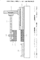
例えば、特許文献1においては、図13に示すように、薄葉化ウェハ41と支持基板42を容易に剥離するために、薄葉化ウェハ41を接着剤43により接着した支持基板42を水平方向に稼動可能なアーム53に接続されたアーム側真空チャック54に吸着するとともに、加熱機構が設けられた真空チャック52で薄葉化ウェハ41の背面を吸着・加熱し、支持台51に設けられた凹部のエッジ(図示は省略)に支持基板42を引っ掛け、それを起点として、アーム53を水平方向に滑らして剥離を行っている。
For example, in
また、特許文献2においては、図14に示すように、薄葉化ウェハ41と支持基板42を容易に剥離するために、薄葉化ウェハ41を接着剤43により接着した支持基板42を水平方向に稼動可能であるとともに、中心軸を回転軸として回転自在なアーム55に接続されたアーム側真空チャック56に吸着するとともに、加熱機構が設けられた真空チャック52で薄葉化ウェハ41の背面を吸着・加熱し、アーム側真空チャック56を正反転方向に回転させた後、アーム55を水平方向に滑らして剥離を行っている。
しかしながら、従来のスライド方法では薄葉化ウェハ面と支持基板を吸着したアーム側真空チャックの稼動方向の平行度が高くないと支持基板が薄葉化ウェハに接触し、破壊する可能性がある。 However, in the conventional sliding method, if the parallelism in the operation direction of the arm-side vacuum chuck that adsorbs the thinned wafer surface and the supporting substrate is not high, the supporting substrate may contact the thinned wafer and break.
例えば、上述の図14に示した正反転方向に回転させる場合、アーム側真空チャック56が水平線に対して0.01°傾斜すると、4インチ(≒10.16cm)の支持基板42の外周では位置が上下方向に約±9μm移動する。 For example, when the arm-side vacuum chuck 56 is tilted by 0.01 ° with respect to the horizontal line when rotating in the forward / reverse direction shown in FIG. Moves approximately ± 9 μm in the vertical direction.
最近では膜厚精度良く、均一に研磨するために、スピンコーティングで塗布する液状熱可塑性接着剤(例えば、スペースリキッドシリーズ〔日化精工株式会社製商品型番〕)が存在するが、この種の接着剤43の固化後の厚みは5〜10μm程度である。そのため、上下方向に約±9μm移動すると薄葉化ウェハ41が支持基板42に接触し、破壊するという問題が発生する。
Recently, there is a liquid thermoplastic adhesive (such as the Space Liquid series [product model number manufactured by Nikka Seiko Co., Ltd.]) that can be applied by spin coating in order to polish uniformly and with good film thickness accuracy. The thickness of the agent 43 after solidification is about 5 to 10 μm. For this reason, if the wafer moves about ± 9 μm in the vertical direction, the
また、ウェハサイズが大きくなればなるほど、外周部での上下移動範囲は大きくなるため、ウェハが破壊されやすくなる。もちろん、熱可塑性接着剤を厚く手塗りし、その厚みが数10μm程度であれば問題ないが、今度は研磨精度が悪くなる。 In addition, the larger the wafer size, the larger the vertical movement range at the outer periphery, so the wafer is more likely to be destroyed. Of course, if the thermoplastic adhesive is thickly hand-painted and the thickness is about several tens of μm, there is no problem, but this time the polishing accuracy becomes worse.
また、上述の図13に示した水平方向にスライドさせる場合も、稼動線が水平線より下方方向にずれると、同様のことが起こる。そのため、従来のスライド方式のウェハ剥がし装置では、平行度精度の高い部品や位置や圧力を検知するためのセンサーが多数必要で、装置自体が高価となり、製造コストが高いという問題がある。 Further, when sliding in the horizontal direction shown in FIG. 13 described above, the same thing occurs when the operating line is shifted downward from the horizontal line. Therefore, the conventional slide-type wafer peeling apparatus requires a large number of sensors for detecting parts and positions and pressures with high parallelism accuracy, and the apparatus itself is expensive, resulting in a high manufacturing cost.
さらに、高軟化点の熱可塑性接着剤を軟化させるために200℃以上の高温に加熱すると、熱伝導によりアーム等の部品の歪みの影響を受けやすく、如何に精度の高い部品やセンサーを配置しても、安定した平行度を保つことが難しく、薄葉化ウェハを破壊する可能性が高いという問題がある。 Furthermore, when heated to a high temperature of 200 ° C or higher in order to soften the high-softening point thermoplastic adhesive, it is easily affected by distortion of parts such as arms due to heat conduction, and how highly accurate parts and sensors are arranged. However, there is a problem that it is difficult to maintain a stable parallelism, and there is a high possibility that the thinned wafer is broken.
したがって、本発明は、被処理基板を破壊することなく確実に剥離するスライド方式の被処理基板剥がし機構を安価に構成することを目的とする。 SUMMARY OF THE INVENTION Accordingly, an object of the present invention is to construct a slide-type substrate removal mechanism that can be reliably peeled without destroying the substrate to be processed at a low cost.
本発明の一観点からは、支持基板を吸着する加熱機構付き真空チャックと、被処理基板を吸着する吸着領域の外周輪郭が前記被処理基板の外周輪郭より小さい真空チャックと、伸縮可能な部材と、前記真空チャックの一方が前記伸縮可能な部材により接続され、水平方向に稼動するアーム状支持部材とを有する基板処理装置が提供される。 From one aspect of the present invention includes a vacuum chuck with a heating mechanism for attracting the support substrate, and the outer contour is less than the vacuum chuck of an outer peripheral contour the target substrate adsorption area for adsorbing the substrate to be processed, and the expandable member There is provided a substrate processing apparatus having one of the vacuum chucks connected by the extendable member and an arm-like support member that operates in a horizontal direction .
また、本発明の別の観点からは、被処理基板を接着剤で接着した支持基板を加熱機構付き真空チャックに吸着する工程と、前記支持基板に接着された被処理基板に対して間隙を介して水平方向に稼動するアーム状支持部材に伸縮可能な部材により接続された真空チャックを対向させる工程と、前記アーム状支持部材を降下させることなく前記真空チャックを降下させて前記被処理基板に当接させて前記伸縮可能な部材に引張力が作用する状態で吸着する工程と、前記アーム状支持部材を水平方向に稼動して前記水平方向に対して垂直方向へ前記伸縮可能な部材に引張力を作用する状態で前記被処理基板を前記支持基板から剥がす工程とを有する基盤処理方法が提供される。 Further, from another aspect of the present invention, a step of adsorbing a support substrate obtained by bonding a substrate to be processed with an adhesive to a vacuum chuck with a heating mechanism and a substrate to be processed bonded to the support substrate via a gap are provided. A vacuum chuck connected by an extendable member to an arm-like support member that operates in a horizontal direction, and the vacuum chuck is lowered without lowering the arm-like support member to contact the substrate to be processed. A step of adsorbing the elastic member in contact with a tensile force acting on the elastic member; and a pulling force applied to the elastic member in a direction perpendicular to the horizontal direction by operating the arm-like support member in a horizontal direction. And a step of peeling the substrate to be processed from the support substrate in a state of acting .
また、本発明のさらに別の観点からは、支持基板に接着剤で接着した被処理基板を真空チャックに吸着する工程と、前記支持基板に対して間隙を介して水平方向に稼働するアーム状支持部材に伸縮可能な部材により接続された加熱機構付き真空チャックを対向させる工程と、前記アーム状支持部材を降下させることなく前記加熱機構付き真空チャックを降下させて前記支持基板に当接させて前記伸縮可能な部材に引張力が作用する状態で吸着する工程と、前記アーム状支持部材を水平方向に稼働して前記水平方向に対して垂直方向へ前記伸縮可能な部材に引張力が作用する状態で前記被処理基板を前記支持基板から剥がす工程とを有する基板処理方法が提供される。 Further, according to still another aspect of the present invention, a process of adsorbing a substrate to be processed, which is bonded to a support substrate with an adhesive, to a vacuum chuck, and an arm-shaped support that operates in a horizontal direction with respect to the support substrate through a gap. A step of facing a vacuum chuck with a heating mechanism connected to a member by an extendable member, and a lowering of the vacuum chuck with a heating mechanism without lowering the arm-like support member to contact the support substrate, A process of adsorbing in a state where a tensile force is applied to the extendable member, and a state in which the arm-like support member is operated in a horizontal direction and a tensile force is applied to the expandable member in a direction perpendicular to the horizontal direction. in a substrate processing method and a step of peeling the substrate to be processed from the support substrate.
開示の上記構成を採ることにより、装置構成を簡略化しつつ、水平方向の平行度精度、熱による稼動部の曲がりなどを補償することができる。このため、装置自体が安価となり、製造コストを下げることができ、さらに、薄葉化ウェハを確実に支持基板から剥離することができる。 By adopting the above-described configuration of the disclosure, it is possible to compensate for the parallelism accuracy in the horizontal direction, the bending of the operating portion due to heat, and the like while simplifying the device configuration. For this reason, the apparatus itself is inexpensive, the manufacturing cost can be reduced, and the thinned wafer can be reliably peeled from the support substrate.
ここで、図1乃至図3を参照して、本発明の実施の形態を説明する。
図1は、本発明の実施の形態のスライド方式被処理基板剥がし装置の概念的構成図であり、ステージ1、ステージ1に固定されて支持基板或いは薄葉化ウェハ等の被処理基板を真空吸着するステージチャック2、ステージ1に固定された水平稼働機構3、水平稼働機構3に固定された垂直稼働機構4、垂直稼働機構4に支持されたアーム5、アーム5に対して伸縮性のバネ6で保持されて被処理基板或いは支持基板を真空吸着するヘッドチャック7、アーム5の先端部に設けられたヘッドチャック押し機構8、及び、剥離した後の被処理基板或いは支持基板を収容する収容台9からなる。
Here, an embodiment of the present invention will be described with reference to FIGS.
FIG. 1 is a conceptual configuration diagram of a slide-type processing substrate peeling apparatus according to an embodiment of the present invention, which is fixed to
この場合、ステージチャック2に支持基板を吸着するか或いは被処理基板を吸着するかは任意であり、少なくとも支持基板を吸着する真空チャックに、例えば、ヒータを内蔵させて加熱機構付き真空チャックとする。また、被処理基板を吸着する真空チャックにも、例えば、ヒータを内蔵させて加熱機構付き真空チャックとしても良いが必須ではない。
In this case, it is arbitrary whether the
このような加熱機構付き真空チャックには、加熱用ヒーター制御装置が設けられているが、ヘッドチャックに加熱機構を設ける場合には、そのための接続配線は、ヘッドチャック7に直接接続しても良いし、或いは、ヘッドチャック押し機構8及びアーム5の内部を挿通するようにしても良い。
Such a vacuum chuck with a heating mechanism is provided with a heater control device for heating. However, when the heating mechanism is provided in the head chuck, the connection wiring for the heating mechanism may be directly connected to the
また、このステージチャック2及びヘッドチャック7にはポンプ、配管、バルブ等の真空系統(図示は省略)が接続されているが、ヘッドチャック7に接続する配管はヘッドチャック7に直接接続しても良いし、或いは、ヘッドチャック押し機構8及びアーム5の内部を挿通するようにしても良い。
The
また、被処理基板を吸着する真空チャックは、その径を被処理基板の径と同じにしても良いが、被処理基板を接着するための接着剤が被処理基板の外周から張り出して真空チャックの表面に粘着するのを防止するために、真空チャックの径を被処理基板の径より小さくすることが望ましい。なお、被処理基板が方形等の円形でない場合には、真空チャックの外周輪郭を被処理基板の外周輪郭より小さくする。 Further, the diameter of the vacuum chuck for adsorbing the substrate to be processed may be the same as the diameter of the substrate to be processed, but an adhesive for bonding the substrate to be processed protrudes from the outer periphery of the substrate to be processed. In order to prevent sticking to the surface, it is desirable to make the diameter of the vacuum chuck smaller than the diameter of the substrate to be processed. When the substrate to be processed is not a circle such as a square, the outer peripheral contour of the vacuum chuck is made smaller than the outer peripheral contour of the substrate to be processed.
そのためには、被処理基板を吸着する真空チャックを被処理基板の径より小径の円筒状としても良いし、吸着面側のみを小径にして凸形にしても良い。 For this purpose, the vacuum chuck for sucking the substrate to be processed may be a cylindrical shape having a diameter smaller than the diameter of the substrate to be processed, or only the suction surface side may have a small diameter and a convex shape.
また、ステージチャック2及びヘッドチャック7は、数十個の直径1mm程度の小穴を開けたタイプのものや数本の溝を掘ったタイプのものでも良いが、多孔質部材からなるポーラスチャックが望ましく、特に、薄葉化ウェハ等の被処理基板を吸着する真空チャックはポーラスチャックが望ましい。
Further, the
また、伸縮性のバネ6は、図1においては引張コイルバネとして示しているが、圧縮コイルバネをボルト等を介してアーム5を挿通してヘッドチャック7に固定しても良い。
また、伸縮性のバネ6は水平移動方向にヘッドチャック押し機構8を挟むように1個ずつの計2個としても良いし、さらに、水平移動方向と直交する水平方向にもヘッドチャック押し機構8を挟むように1個ずつ設けて計4個としても良い。
Further, although the
Further, the
まず、伸縮性のバネ6としては、伸縮性のバネ6がヘッドチャック7の重力と釣り合った状態からさらに伸張した時に発生する引張力が、ヘッドチャック7およびステージチャック2の吸着力、かつ、熱により軟化した接着剤の垂直方向の表面張力による接着力よりも弱いバネを選択することが必要条件となる。
First, as the
この場合の垂直接着力Fv 〔N〕は、図2に示すように、被処理基板23と支持基板21との接触面積をA〔mm2 〕、接着剤22の表面張力をγ、接着剤22の厚みをH〔μm〕とした場合、
Fv =A×2γ/H ・・・(1)
で表される。
In this case, the vertical adhesive force F v [N] is, as shown in FIG. 2, the contact area between the substrate to be processed 23 and the
F v = A × 2γ / H (1)
It is represented by
さらに、ヘッドチャック7或いはステージチャック2の吸着力により発生する摩擦力が軟化した接着剤22の粘性抵抗力よりも強いことも必要条件となる。この場合の粘性抵抗力FA 〔N〕は、図2に示すように、被処理基板23と支持基板21との接触面積をA〔mm2 〕、接着剤22の粘度をv〔cp〕、接着剤22の厚みをH〔μm〕、スライド速度をV〔mm/秒〕とした場合、
FA =A×v×V/H ・・・(2)
で表される。
Further, it is a necessary condition that the frictional force generated by the adsorption force of the
F A = A × v × V / H (2)
It is represented by
バネの引張力が強すぎると、ヘッドチャック7及びステージチャック2がサンプルから外れる、あるいは、被処理基板23と支持基板21を無理やり引き剥がすことになる。 また、真空チャックの吸着力が弱いと、スライドさせたときにどちらか片側の真空チャックからサンプルが外れることになる。
If the tension force of the spring is too strong, the
次に、図3を参照して、本発明の被処理基板剥がしの原理を説明する。上述の必要条件が維持された状態で支持基板21と被処理基板23をスライドさせると、接着面の面積Aが狭くなり、垂直接着力Fv が徐々に低下する。ヘッドチャック7は常に伸縮性のバネ6でアーム側に引っ張られているため、ヘッドチャック7を少しずつアーム側へ引き上げながら剥離することになり、被処理基板23を支持基板21に接触させずに支持基板21から剥離できる。なお、接着剤22としては、熱可塑性接着剤、例えば、市販のテルペンフェノール樹脂を含有する液状接着剤を用いる。
Next, with reference to FIG. 3, the principle of peeling the substrate to be processed according to the present invention will be described. When the
以上を前提として、次に、本発明の実施例1の薄葉化ウェハ剥がし装置を説明する。図4は本発明の実施例1の薄葉化ウェハ剥がし装置の概念的構成図であり、基本的には上記の図1の構成と同じであり、ステージ11、ステージ11に固定されて支持基板を真空吸着する加熱機構付きのステージチャック12、ステージ11に固定された水平稼働機構13、水平稼働機構13に固定された垂直稼働機構14、垂直稼働機構14に支持されたアーム15、アーム15に対して引張コイルバネ16で保持されて薄葉化ウェハ真空吸着するヘッドチャック17、アーム15の先端部に設けられたヘッドチャック押し機構18、及び、剥離した後の薄葉化ウェハを収容する薄葉化ウェハ収容台19からなる。なお、真空吸引するための真空ポンプは、市販のダイヤフラムポンプを用いて、到達真空度は−80kPa(ゲージ圧)とする。
Based on the above, the thinned wafer peeling apparatus according to the first embodiment of the present invention will be described next. FIG. 4 is a conceptual configuration diagram of the thinned wafer peeling apparatus according to the first embodiment of the present invention, which is basically the same as the configuration of FIG. 1 described above. The support substrate is fixed to the
ヘッドチャック17及びステージチャック12には、例えば、気孔径55μm、気孔率33%の多孔質部材からなる市販のポーラスチャックを用いる。従来のタイプの真空チャックは小穴や溝の周辺が特に強く真空引きされるため、薄葉化ウェハの特定部位の歪みが大きくなるが、ポーラスチャックはポーラスの粒を細かくすれば、薄葉化ウェハの歪みが少なくなり、特に、厚さが、100μm程度の薄葉化ウェハに好適となる。
For the
また、真空チャックの吸着力は、真空引きされる面積とその真空度の積で決まるが、ポーラスチャックは吸着面全体で均一に真空引きするため、小穴や溝のタイプの真空チャックより吸着力が強い。例えば、ポーラスチャックの吸着面直径が65mmの場合、到達真空度が−80kPa(ゲージ圧)の時、その吸着力は70.7Nとなる。 The suction force of the vacuum chuck is determined by the product of the area to be evacuated and the degree of vacuum. However, since the porous chuck uniformly evacuates the entire suction surface, the suction force is smaller than that of the small hole or groove type vacuum chuck. strong. For example, when the suction surface diameter of the porous chuck is 65 mm, the suction force is 70.7 N when the ultimate vacuum is −80 kPa (gauge pressure).
一般的な金属同士の摩擦係数は0.5〜0.6とされているが、ポーラスチャックは非常に細かい凹凸表面であるため、通常のステンレス製真空チャックステージよりも摩擦力が強いと考えられる。ここで、ポーラスチャックの摩擦係数を0.6とすると、摩擦力は42.4Nとなり、後述する熱可塑性接着剤の粘性抵抗力1.7Nよりも十分強いことがわかる。一方、従来の65個の直径1mmの小穴のタイプの場合、薄葉化ウェハの歪みにより小穴エリアを完全に閉じてしまうと、吸着力は4.4Nとなり、摩擦係数を0.5とすると、摩擦力は2.2Nとなる。もし、後述する熱可塑性接着剤を200℃で軟化させた場合、その粘性抵抗力は4.3Nになるので、スライドさせるとチャックは外れてしまうことになる。 The friction coefficient between general metals is 0.5 to 0.6, but the porous chuck has a very fine uneven surface, so it is thought that the friction force is stronger than the normal stainless steel vacuum chuck stage. . Here, when the coefficient of friction of the porous chuck is 0.6, the frictional force is 42.4N, which is sufficiently stronger than the viscous resistance force 1.7N of the thermoplastic adhesive described later. On the other hand, in the case of 65 conventional small hole types with a diameter of 1 mm, if the small hole area is completely closed due to distortion of the thinned wafer, the suction force becomes 4.4 N, and the friction coefficient is 0.5. The force is 2.2N. If the thermoplastic adhesive described later is softened at 200 ° C., the viscous resistance is 4.3 N, so that the chuck will come off when it is slid.
次に、引張コイルバネ16としては、例えば、初張力3.75N、バネ定数1N/mm、最大荷重21.5N、最大たわみ範囲18mmの引張コイルバネを2個、ヘッドチャック17のスライド方向にヘッドチャック押し機構18を挟んで対向するように設ける。
Next, as the
ヘッドチャック17の重量を例えば、0.9kgとすると、重力は8.8Nとなるので、2個の引張コイルバネ16が0.65mm伸びた状態で、ヘッドチャック17と釣り合う。釣り合い状態から、2個の引張コイルバネ16を0.5mm伸ばした場合、ヘッドチャック17には常に1N(=0.5〔mm〕×1〔N/mm〕×2〔個〕)の引張力が作用している。
If the weight of the
ヘッドチャック17とステージチャック12、及び、軟化した熱可塑性接着剤の垂直方向の接着力は引張コイルバネ16の引張力よりも十分強いため、引張コイルバネ16によりヘッドチャック17が外れたり、接着剤界面より無理やり引き剥がすことはない。理論的には薄葉化ウェハと支持基板の重なり合う面積Aが100mm2 程度より狭くなったとき、引張コイルバネ16の引張力が勝り、ヘッドチャック17を完全に引き上げることになる。
Since the vertical adhesive force of the
次に、図5乃至図7を参照して、本発明の実施例1の薄葉化ウェハ剥がし工程を説明するが、その前に、薄葉化ウェハを支持基板に接着するための熱可塑性接着剤について説明する。熱可塑性接着剤としては、例えば、市販のテルペンフェノール樹脂を含有する液状接着剤を用いる。 Next, the thinned wafer peeling process according to the first embodiment of the present invention will be described with reference to FIGS. 5 to 7. Before that, a thermoplastic adhesive for bonding the thinned wafer to the support substrate will be described. explain. As the thermoplastic adhesive, for example, a liquid adhesive containing a commercially available terpene phenol resin is used.
この液状接着剤は、固化前の粘度は73cpで、ウェハにスピンコーティングできる。
スピンコータを用いて例えば、2000rpm、3秒でウェハにスピンコーティングした後、ホットプレートで100℃、180℃でそれぞれ1分ずつベーキングを行い、有機溶媒を蒸発させる。
This liquid adhesive has a viscosity of 73 cp before solidification and can be spin-coated on a wafer.
For example, after spin coating on a wafer at 2000 rpm for 3 seconds using a spin coater, baking is performed at 100 ° C. and 180 ° C. for 1 minute each to evaporate the organic solvent.
固化後の膜厚は約6μmで、支持基板には180℃に加熱しながら、0.15MPa(ゲージ圧)で加圧して接着する。因に、固化後の接着力は2.6N/mm2 であり、軟化点は155℃で、流動開始温度は169℃である。流動開始後の接着剤の粘度は、200℃で9400cp、220℃で2200cp、240℃で780cpである。 The film thickness after solidification is about 6 μm, and is bonded to the support substrate by applying pressure of 0.15 MPa (gauge pressure) while heating to 180 ° C. Incidentally, the adhesive force after solidification is 2.6 N / mm 2 , the softening point is 155 ° C., and the flow start temperature is 169 ° C. The viscosity of the adhesive after the start of flow is 9400 cp at 200 ° C., 2200 cp at 220 ° C., and 780 cp at 240 ° C.
ここで、接触面積Aを3インチ(≒7.62cm)のウェハと同じとし、スライド速度Vを1mm/秒とすると、220℃の時の粘性抵抗力FA は1.7Nとなる。一方、一般的に液体物質の表面張力は水の表面張力の半分程度であることから、軟化した熱可塑性接着剤の表面張力を36mN/mとしてウェハ面に垂直方向に作用する力を計算すると、約54Nとなる。 Here, assuming that the contact area A is the same as that of a 3 inch (≈7.62 cm) wafer and the slide speed V is 1 mm / second, the viscous resistance force FA at 220 ° C. is 1.7 N. On the other hand, since the surface tension of the liquid substance is generally about half of the surface tension of water, when the surface tension of the softened thermoplastic adhesive is 36 mN / m and the force acting in the direction perpendicular to the wafer surface is calculated, It will be about 54N.
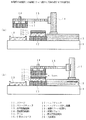
次に、薄葉化ウェハの剥がし工程を説明すると、まず、図5(a)に示すように、まず、ステージチャック12を予め設定温度、例えば、270℃まで加熱した後、薄葉化ウェハ24を熱可塑性接着剤25で支持基板26に接着したサンプルをステージチャック12に載せ、真空引きしながらサンプルを加熱する。この場合、ステージ表面は温度モニター用熱電対の位置から少し離れているため、実際にはステージ表面温度は設定温度よりも30℃程度低くなっている。
Next, the process of peeling the thinned wafer will be described. First, as shown in FIG. 5A, the
次いで、図5(b)に示すように、水平稼働機構13及び垂直稼働機構14を用いて、アーム15に対して引張コイルバネ16により支持したヘッドチャック17をサンプルに対して、例えば、0.5mmの間隙を介して対向配置する。この場合、垂直稼働機構14を用いてヘッドチャック17を徐々に降下させて0.5mmの間隙としても良いし、ヘッドチャック17を一旦、薄葉化ウェハ24に当接したのち、垂直稼働機構14を用いてヘッドチャック17を徐々に上昇させて0.5mmの間隙としても良い。
Next, as shown in FIG. 5B, the
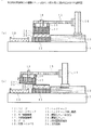
次いで、図6(a)に示すように、ヘッドチャック17を真空引きしながら、ヘッドチャック押し機構18でヘッドチャック17をゆっくり下方に押し、サンプルに吸着させる。この状態で、引張コイルバネ16は0.5mm程度伸び、ヘッドチャック17をアーム側に引っ張る方向に力を作用させるため、薄葉化ウェハ24を支持基板26に押さえつけることはない。
Next, as shown in FIG. 6A, while the
この時、ヘッドチャック17への放熱によりステージチャック12のモニター温度が240℃まで低下した。このため、ヘッドチャック17を吸着させたまま、10分間加熱放置した。この熱伝導により稼動部に歪みが生じたとしても、引張コイルバネ16の伸縮で十分補償される。
At this time, the monitor temperature of the
次いで、図6(b)に示すように、ステージチャック12の温度が十分回復した後、水平稼動機構13でヘッドチャック17を水平方向(図においては左右方向)にゆっくりスライドさせる。この時、ヘッドチャック17は常に引張コイルバネ16でアーム側に引っ張られているため、接触面が狭くなり、垂直方向の接着力Fv が低下して徐々に持ち上がってくる。このため、薄葉化ウェハ24を支持基板26に接触させることなく、剥離することができる。
Next, as shown in FIG. 6B, after the temperature of the
但し、引張コイルバネ16によるヘッドチャック17の引張力が強すぎて、スライド途中に支持基板26から薄葉化ウェハ24を引き剥がしてしまうような場合には、ヘッドチャック押し機構18を使用せずに、先に垂直稼動機構14、例えば、マイクロゲージを使ってフリー状態のヘッドチャック17を薄葉化ウェハ24の背面にチャックさせた後に、マイクロゲージで0.1mm程度アーム15を上昇させて引張コイルバネ16をわずかに伸ばしておくと良い。また、熱可塑性接着剤の種類を変更したとしても、その接着力に適したばね定数の引張コイルバネ16に交換するだけで良い。
However, if the tension force of the
次いで、図7(a)に示すように、水平稼働機構13によるスライドをさらに進めると、薄葉化ウェハ24が完全に支持基板26から分離する。
Next, as shown in FIG. 7A, when the slide by the
最後に、図7(b)に示すように、ヘッドチャック17を薄葉化ウェハ収容台19の上方まで移動させたのち、ヘッドチャック17の真空吸引を解除して薄葉化ウェハ24を薄葉化ウェハ収容台19に落とし、剥離工程が完了する。
Finally, as shown in FIG. 7B, after the
このように、本発明の実施例1においては、上述の機構を採用することにより、装置構成を簡略化しつつ、水平方向の平行度精度、熱による稼動部の曲がりなどを補償することができるため、装置自体が安価となり、製造コストを下げることができる。 As described above, in the first embodiment of the present invention, by adopting the above-described mechanism, it is possible to compensate for the parallelism accuracy in the horizontal direction, the bending of the operating part due to heat, and the like while simplifying the device configuration. The device itself is inexpensive and the manufacturing cost can be reduced.
次に、図1を借用して、本発明の実施例2のスライド式薄葉化ウェハ剥がし装置を説明する。この本発明の実施例2においては、ステージチャック2で薄葉化ウェハを吸着し、ヘッドチャック17で支持基板を吸着するものであり、収容台9は支持基板収容台となる。
Next, referring to FIG. 1, a slide type thinned wafer peeling apparatus according to a second embodiment of the present invention will be described. In the second embodiment of the present invention, the thinned wafer is sucked by the
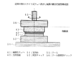
次に、図8を参照して、本発明の実施例3のスライド式薄葉化ウェハ剥がし装置を説明するが、この実施例3においては引張コイルバネの数が異なるだけであるので、ヘッドチャック及び伸縮性バネの構成のみを説明する。図8は、本発明の実施例3の伸縮性バネ取付け部の概念的構成説明図であり、図8(a)は概念的側面図であり、図8(b)は概念的平面図である。図に示すように、アーム15の先端部20を円盤状にして、4つの引張コイルバネ16によりヘッドチャック17をアーム15に支持したものである。
Next, referring to FIG. 8, a slide type thinned wafer peeling apparatus according to a third embodiment of the present invention will be described. However, in this third embodiment, only the number of tension coil springs is different. Only the structure of the elastic spring will be described. FIG. 8 is an explanatory diagram of a conceptual configuration of a stretchable spring mounting portion according to a third embodiment of the present invention, FIG. 8 (a) is a conceptual side view, and FIG. 8 (b) is a conceptual plan view. . As shown in the figure, the
この実施例3においては、4つの引張コイルバネ16によりヘッドチャック17を支持しているので、剥離動作時においてスライド方向と直交する水平方向における薄葉化ウェハ24の揺動が安定する。
In the third embodiment, since the
次に、図9を参照して、本発明の実施例4のスライド式薄葉化ウェハ剥がし装置を説明するが、この実施例4においては伸縮性バネの構成が異なるだけであるので、ヘッドチャック及び伸縮性バネの構成のみを説明する。図9は、本発明の実施例4の伸縮性バネ取付け部の概念的構成説明図であり、アーム15の上からアーム15を貫通するボルト31により圧縮コイルバネ32を設けたものである。
Next, referring to FIG. 9, a slide type thinned wafer peeling apparatus according to a fourth embodiment of the present invention will be described. In this fourth embodiment, only the configuration of the stretchable spring is different. Only the configuration of the elastic spring will be described. FIG. 9 is a conceptual explanatory diagram of the stretchable spring mounting portion according to the fourth embodiment of the present invention, in which a
この本発明の実施例4においては伸縮性バネとして圧縮コイルバネを用いているので、引張コイルバネのように取付けのためのフック機構が不要になるため、伸縮性バネ機構を簡単に且つ小型に構成することが可能になる。なお、この場合も圧縮コイルバネ32を4個設けても良い。 In the fourth embodiment of the present invention, since the compression coil spring is used as the stretchable spring, a hook mechanism for attachment is not required unlike the tension coil spring, and thus the stretchable spring mechanism is simply and compactly configured. It becomes possible. In this case, four compression coil springs 32 may be provided.
次に、図10を参照して、本発明の実施例5のスライド式薄葉化ウェハ剥がし装置を説明するが、この実施例5においてはヘッドチャックに加熱機構を設けた点で異なるだけであるので、ヘッドチャックの構成のみを説明する。図10は、本発明の実施例5のヘッドチャックの概念的構成図であり、ヘッドチャック17の内部に加熱用ヒータ33を設けたものである。なお、この場合の加熱用ヒータ33に対する接続配線34は、ヘッドチャック17の側面から取り出すようにしても良い。
Next, a slide type thinned wafer peeling apparatus according to a fifth embodiment of the present invention will be described with reference to FIG. 10. However, the fifth embodiment is different only in that a heating mechanism is provided in the head chuck. Only the configuration of the head chuck will be described. FIG. 10 is a conceptual configuration diagram of a head chuck according to a fifth embodiment of the present invention, in which a
この本発明の実施例5においては、ヘッドチャックに加熱機構を設けているので、ヘッドチャック17を薄葉化ウェハ24の背面に吸着させた際に、ヘッドチャック17への放熱によりステージチャック12の温度の低下を抑制できるため、スライドさせるまでの処理時間を早くすることができ、それによって、スループットが向上する。
In the fifth embodiment of the present invention, since the heating mechanism is provided in the head chuck, when the
次に、図11を参照して、本発明の実施例6のスライド式薄葉化ウェハ剥がし装置を説明するが、この実施例6においてはヘッドチャックの断面形状が異なるだけであるので、ヘッドチャックの構成のみを説明する。図11は、本発明の実施例6のヘッドチャックの概念的構成図であり、ヘッドチャック35の先端に吸着する薄葉化ウェハ24より小径の小径吸着部36を設けて断面形状を凸形にしたものである。
Next, referring to FIG. 11, a slide type thinned wafer peeling apparatus according to a sixth embodiment of the present invention will be described. In this sixth embodiment, only the cross-sectional shape of the head chuck is different. Only the configuration will be described. FIG. 11 is a conceptual configuration diagram of a head chuck according to a sixth embodiment of the present invention, in which a small-diameter adsorption portion 36 having a smaller diameter than the thinned
この場合、例えば、3インチウェハ(≒76.2mm)に対して、小径吸着部36の直径を65〜75mm、例えば、70mmとし、段差を0.1〜1mm、例えば、0.5mmとしたものである。小径吸着部36の直径を65mm未満にすると薄葉化工程、即ち、研磨工程におけるウェハの周辺部に対する押し付けが十分ではなくなり、一方、75mmを超えると熱可塑性接着剤25の張り出しによる薄葉化ウェハ24のヘッドチャック35への貼り付けが発生し易くなる。なお、この小径吸着部36の直径と段差は、ウェハの直径に殆ど依存しないので、他のサイズのウェハの場合も同様の直径と段差で良い。
In this case, for example, for a 3-inch wafer (≈76.2 mm), the diameter of the small-diameter suction portion 36 is 65 to 75 mm, for example 70 mm, and the step is 0.1 to 1 mm, for example 0.5 mm. It is. If the diameter of the small diameter adsorbing portion 36 is less than 65 mm, the thinning process, that is, the pressing to the peripheral portion of the wafer in the polishing process is not sufficient, whereas if the diameter exceeds 75 mm, the thinned
この本発明の実施例6においては、ヘッドチャック35を凸形にしているので、水平方向にスライドさせた時に熱可塑性接着剤25が張り出したとしても、薄葉化ウェハ24がヘッドチャック35に貼り付くことはなく、真空吸引を解除するだけで剥離した薄葉化ウェハ24を容易にヘッドチャック35から離脱させることができる。なお、ヘッドチャックの直径が薄葉化ウェハと同一径或いは大きい場合には、水平方向にスライドさせた時に張り出した熱可塑性接着剤によって薄葉化ウェハがヘッドチャックに貼り付くことがあり、真空吸引を解除するだけでは剥離した薄葉化ウェハをヘッドチャック35から離脱させることが困難になる。
In the sixth embodiment of the present invention, since the head chuck 35 is convex, even if the thermoplastic adhesive 25 protrudes when it is slid in the horizontal direction, the thinned
次に、図12を参照して、本発明の実施例7のスライド式薄葉化ウェハ剥がし装置を説明するが、この実施例7においてはヘッドチャックの直径が異なるだけであるので、ヘッドチャックの構成のみを説明する。図12は、本発明の実施例7のヘッドチャックの概念的構成図であり、ヘッドチャック37の直径を吸着する薄葉化ウェハ24より小径にしたものである。この場合も、例えば、3インチウェハ(≒76.2mm)に対して、ヘッドチャック37の直径を65〜75mm、例えば、70mmとする。
Next, referring to FIG. 12, a slide type thinned wafer peeling apparatus according to a seventh embodiment of the present invention will be described. In this seventh embodiment, only the diameter of the head chuck is different. I will explain only. FIG. 12 is a conceptual configuration diagram of the head chuck according to the seventh embodiment of the present invention, in which the diameter of the head chuck 37 is made smaller than that of the thinned
この本発明の実施例7においては、ヘッドチャック37の直径自体を薄葉化ウェハの直径より小径にしているので、水平方向にスライドさせた時に熱可塑性接着剤25が張り出したとしても、薄葉化ウェハ24がヘッドチャック37に貼り付くことはなく、真空吸引を解除するだけで剥離した薄葉化ウェハ24を容易にヘッドチャック37から離脱させることができる。
In the seventh embodiment of the present invention, since the diameter of the head chuck 37 itself is smaller than the diameter of the thinned wafer, even if the thermoplastic adhesive 25 protrudes when it is slid in the horizontal direction, the thinned wafer. 24 does not stick to the head chuck 37, and the thinned
以上、本発明の各実施例を説明してきたが、本発明は、各実施例に示した構成・条件に限られるものではない。例えば、上記の実施例では薄葉化ウェハをチャックし、稼動するヘッドチャック側にバネを設ける構造としたが、支持基板をチャックするステージチャック側を稼動させることも可能であり、ステージチャック側にバネを設ける構造にしても構わない。 The embodiments of the present invention have been described above, but the present invention is not limited to the configurations and conditions shown in the embodiments. For example, in the above embodiment, the structure is such that the thin wafer is chucked and the spring is provided on the head chuck side that operates, but the stage chuck side that chucks the support substrate can also be operated, and the spring is provided on the stage chuck side. A structure may be provided.
また、上記の各実施例においては、剥離対象を薄葉化ウェハとしているが、薄葉化ウェハに限られるものではなく、例えば、ダマシン法により銅埋込配線を形成する場合の研磨工程において支持基板に接着させたウェハの剥離工程等にも適用されるものである。 Further, in each of the above embodiments, the target to be peeled is a thinned wafer, but it is not limited to the thinned wafer. For example, in the polishing process when copper embedded wiring is formed by the damascene method, the support substrate is used. The present invention is also applied to a peeling process of a bonded wafer.
また、剥離対象となる被処理基板の形状は円盤状である必要はなく、方形状であっても良く、その場合には、ヘッドチャックの平面形状は、剥離対象となる被処理基板の形状と相似の形状とすれば良い。 Further, the shape of the substrate to be peeled does not need to be a disk shape, and may be a square shape. In this case, the planar shape of the head chuck is the same as the shape of the substrate to be peeled. A similar shape may be used.
1 ステージ
2 ステージチャック
3 水平稼働機構
4 垂直稼働機構
5 アーム
6 伸縮性のバネ
7 ヘッドチャック
8 ヘッドチャック押し機構
9 収容台
11 ステージ
12 ステージチャック
13 水平稼働機構
14 垂直稼働機構
15 アーム
16 引張コイルバネ
17 ヘッドチャック
18 ヘッドチャック押し機構
19 薄葉化ウェハ収容台
20 先端部
21 支持基板
22 接着剤
23 被処理基板
24 薄葉化ウェハ
25 熱可塑性接着剤
26 支持基板
31 ボルト
32 圧縮コイルバネ
33 加熱用ヒータ
34 接続配線
35 ヘッドチャック
36 小径吸着部
37 ヘッドチャック
41 薄葉化ウェハ
42 支持基板
43 接着剤
51 支持台
52 真空チャック
53 アーム
54 アーム側真空チャック
55 アーム
56 アーム側真空チャック
DESCRIPTION OF
Claims (7)
被処理基板を吸着する吸着領域の外周輪郭が前記被処理基板の外周輪郭より小さい真空チャックと、
伸縮可能な部材と、
前記真空チャックの一方が前記伸縮可能な部材により接続され、水平方向に稼動するアーム状支持部材と
を有する基板処理装置。 A vacuum chuck with a heating mechanism for adsorbing a support substrate ;
A vacuum chuck in which an outer periphery contour of a suction region that sucks the substrate to be processed is smaller than an outer periphery contour of the substrate to be processed ;
A stretchable member;
One of the vacuum chucks is connected by the extendable member, and an arm-like support member that operates in a horizontal direction;
A substrate processing apparatus.
前記アーム状支持部材に設けられ、前記真空チャックを押す真空チャック押し機構とA vacuum chuck pushing mechanism provided on the arm-shaped support member and pushing the vacuum chuck;
を有している請求項1乃至請求項3のいずれか1項に記載の基板処理装置。The substrate processing apparatus of any one of Claim 1 thru | or 3 which has these.
前記支持基板に接着された被処理基板に対して間隙を介して水平方向に稼働するアーム状支持部材に伸縮可能な部材により接続された真空チャックを対向させる工程と、
前記アーム状支持部材を降下させることなく前記真空チャックを降下させて前記被処理基板に当接させて前記伸縮可能な部材に引張力が作用する状態で吸着する工程と、
前記アーム状支持部材を水平方向に稼働して前記水平方向に対して垂直方向へ前記伸縮可能な部材に引張力が作用する状態で前記被処理基板を前記支持基板から剥がす工程と
を有する基板処理方法。 Adsorbing a substrate to be processed to be bonded with an adhesive to a vacuum chuck with a heating mechanism;
A step of facing a vacuum chuck connected by an extendable member to an arm-like support member that operates in a horizontal direction through a gap with respect to a substrate to be processed bonded to the support substrate;
A step of lowering the vacuum chuck without lowering the arm-shaped support member and bringing the vacuum chuck into contact with the substrate to be processed, and adsorbing in a state where a tensile force acts on the extendable member;
A substrate process comprising: operating the arm-shaped support member in a horizontal direction and peeling the substrate to be processed from the support substrate in a state in which a tensile force is applied to the member that can extend and contract in a direction perpendicular to the horizontal direction. Method.
前記支持基板に対して間隙を介して水平方向に稼働するアーム状支持部材に伸縮可能な部材により接続された加熱機構付き真空チャックを対向させる工程と、
前記アーム状支持部材を降下させることなく前記加熱機構付き真空チャックを降下させて前記支持基板に当接させて前記伸縮可能な部材に引張力が作用する状態で吸着する工程と、
前記アーム状支持部材を水平方向に稼働して前記水平方向に対して垂直方向へ前記伸縮可能な部材に引張力が作用する状態で前記被処理基板を前記支持基板から剥がす工程と
を有する基板処理方法。 A process of adsorbing a substrate to be processed bonded to a support substrate with an adhesive to a vacuum chuck;
A step of facing a vacuum chuck with a heating mechanism connected by an extendable member to an arm-like support member that operates in a horizontal direction through a gap with respect to the support substrate;
A step of lowering the vacuum chuck with a heating mechanism without lowering the arm-like support member and bringing it into contact with the support substrate and adsorbing it in a state where a tensile force acts on the extendable member;
A substrate process comprising: operating the arm-shaped support member in a horizontal direction and peeling the substrate to be processed from the support substrate in a state in which a tensile force is applied to the member that can extend and contract in a direction perpendicular to the horizontal direction. Method.
Priority Applications (1)
| Application Number | Priority Date | Filing Date | Title |
|---|---|---|---|
| JP2008139278A JP5487560B2 (en) | 2008-05-28 | 2008-05-28 | Substrate processing apparatus and substrate processing method |
Applications Claiming Priority (1)
| Application Number | Priority Date | Filing Date | Title |
|---|---|---|---|
| JP2008139278A JP5487560B2 (en) | 2008-05-28 | 2008-05-28 | Substrate processing apparatus and substrate processing method |
Publications (2)
| Publication Number | Publication Date |
|---|---|
| JP2009289878A JP2009289878A (en) | 2009-12-10 |
| JP5487560B2 true JP5487560B2 (en) | 2014-05-07 |
Family
ID=41458827
Family Applications (1)
| Application Number | Title | Priority Date | Filing Date |
|---|---|---|---|
| JP2008139278A Expired - Fee Related JP5487560B2 (en) | 2008-05-28 | 2008-05-28 | Substrate processing apparatus and substrate processing method |
Country Status (1)
| Country | Link |
|---|---|
| JP (1) | JP5487560B2 (en) |
Families Citing this family (11)
| Publication number | Priority date | Publication date | Assignee | Title |
|---|---|---|---|---|
| JP5572039B2 (en) * | 2010-08-30 | 2014-08-13 | 秀和工業株式会社 | Wafer peeling method and apparatus |
| KR101282104B1 (en) | 2011-03-24 | 2013-07-04 | 주식회사 엔티에스 | Automatic demounting apparatus and method thereof |
| WO2012140987A1 (en) * | 2011-04-12 | 2012-10-18 | 東京エレクトロン株式会社 | Separation device, separation system, and separation method |
| WO2012140988A1 (en) * | 2011-04-12 | 2012-10-18 | 東京エレクトロン株式会社 | Separation method, separation device, and separation system |
| JP5580806B2 (en) * | 2011-11-01 | 2014-08-27 | 東京エレクトロン株式会社 | Peeling apparatus, peeling system, peeling method, program, and computer storage medium |
| JP2013120903A (en) * | 2011-12-08 | 2013-06-17 | Tokyo Electron Ltd | Peeling device, peeling system, peeling method, program, and computer storage medium |
| JP5635019B2 (en) * | 2012-01-17 | 2014-12-03 | 東京エレクトロン株式会社 | Peeling device, peeling system, peeling method and peeling program |
| JP5912805B2 (en) * | 2012-04-24 | 2016-04-27 | 株式会社ディスコ | Plate transfer method |
| JP5926700B2 (en) * | 2013-04-30 | 2016-05-25 | 東京応化工業株式会社 | Support body separating apparatus and support body separating method |
| JP6189123B2 (en) * | 2013-07-24 | 2017-08-30 | リンテック株式会社 | Transport method and transport device |
| CN113299576B (en) * | 2020-02-21 | 2022-11-22 | 济南晶正电子科技有限公司 | Mechanical film separating device |
Family Cites Families (2)
| Publication number | Priority date | Publication date | Assignee | Title |
|---|---|---|---|---|
| JP3918556B2 (en) * | 2001-12-28 | 2007-05-23 | 三菱電機株式会社 | Sticking wafer separating apparatus and sticking wafer separating method |
| JP2004063645A (en) * | 2002-07-26 | 2004-02-26 | Enzan Seisakusho:Kk | Protection member exfoliation apparatus of semiconductor wafer |
-
2008
- 2008-05-28 JP JP2008139278A patent/JP5487560B2/en not_active Expired - Fee Related
Also Published As
| Publication number | Publication date |
|---|---|
| JP2009289878A (en) | 2009-12-10 |
Similar Documents
| Publication | Publication Date | Title |
|---|---|---|
| JP5487560B2 (en) | Substrate processing apparatus and substrate processing method | |
| US9381729B2 (en) | Device for detaching a product substrate off a carrier substrate | |
| TWI641068B (en) | Flexible carrier mount, device and method for detaching a carrier substrate | |
| JP4985513B2 (en) | Method and apparatus for peeling electronic parts | |
| US20150279716A1 (en) | Apparatus and method for detaching chip | |
| US9922862B2 (en) | Device and method for loosening a first substrate | |
| JP6140194B2 (en) | Method for temporarily bonding a product substrate to a carrier substrate | |
| US8574398B2 (en) | Apparatus and method for detaping an adhesive layer from the surface of ultra thin wafers | |
| US20080053620A1 (en) | Method for the bonding of disk-shaped substrates and apparatus for carrying out the method | |
| JP2012524419A (en) | Apparatus and method for separating a substrate from a carrier substrate | |
| JP2015505164A (en) | Flexible substrate holding apparatus, apparatus and method for peeling first substrate | |
| JP2006237492A (en) | Wafer processing apparatus | |
| JP4559183B2 (en) | Tape bonding device | |
| JP4698452B2 (en) | Substrate bonding method and apparatus using the same | |
| JP2020009982A (en) | Polishing method of semiconductor chip | |
| JP5845775B2 (en) | Method for joining thin film pieces | |
| KR101403850B1 (en) | System for holding large scale substrate | |
| JP2001308033A (en) | Method for fixing wafer | |
| JP6469070B2 (en) | Method for peeling a first substrate from a second substrate and use of a flexible substrate holding device | |
| JP4319859B2 (en) | Method for peeling brittle members | |
| JP2011003691A (en) | Pad transfer mechanism for semiconductor substrate | |
| JP4836042B2 (en) | Peeling device | |
| JP5227554B2 (en) | Substrate processing apparatus and substrate processing method | |
| JP6312469B2 (en) | Substrate adsorption / detachment mechanism, substrate transfer device, and vacuum device | |
| CN112838022A (en) | Stripping device |
Legal Events
| Date | Code | Title | Description |
|---|---|---|---|
| A621 | Written request for application examination |
Free format text: JAPANESE INTERMEDIATE CODE: A621 Effective date: 20101119 |
|
| RD03 | Notification of appointment of power of attorney |
Free format text: JAPANESE INTERMEDIATE CODE: A7423 Effective date: 20110915 |
|
| A977 | Report on retrieval |
Free format text: JAPANESE INTERMEDIATE CODE: A971007 Effective date: 20130321 |
|
| A131 | Notification of reasons for refusal |
Free format text: JAPANESE INTERMEDIATE CODE: A131 Effective date: 20130423 |
|
| A521 | Written amendment |
Free format text: JAPANESE INTERMEDIATE CODE: A523 Effective date: 20130624 |
|
| TRDD | Decision of grant or rejection written | ||
| A01 | Written decision to grant a patent or to grant a registration (utility model) |
Free format text: JAPANESE INTERMEDIATE CODE: A01 Effective date: 20140128 |
|
| A61 | First payment of annual fees (during grant procedure) |
Free format text: JAPANESE INTERMEDIATE CODE: A61 Effective date: 20140210 |
|
| R150 | Certificate of patent or registration of utility model |
Ref document number: 5487560 Country of ref document: JP Free format text: JAPANESE INTERMEDIATE CODE: R150 |
|
| LAPS | Cancellation because of no payment of annual fees |